US11388697B2 - HARQ process for multiuser broadcast transmission node - Google Patents

HARQ process for multiuser broadcast transmission node Download PDF

Info

Publication number
US11388697B2
US11388697B2 US17/040,838 US201917040838A US11388697B2 US 11388697 B2 US11388697 B2 US 11388697B2 US 201917040838 A US201917040838 A US 201917040838A US 11388697 B2 US11388697 B2 US 11388697B2
Authority
US
United States
Prior art keywords
devices
relay node
data
control information
broadcast transmission
Prior art date
Legal status (The legal status is an assumption and is not a legal conclusion. Google has not performed a legal analysis and makes no representation as to the accuracy of the status listed.)
Active, expires
Application number
US17/040,838
Other versions
US20210022114A1 (en
Inventor
Amit Kalhan
Current Assignee (The listed assignees may be inaccurate. Google has not performed a legal analysis and makes no representation or warranty as to the accuracy of the list.)
Kyocera Corp
Original Assignee
Kyocera Corp
Priority date (The priority date is an assumption and is not a legal conclusion. Google has not performed a legal analysis and makes no representation as to the accuracy of the date listed.)
Filing date
Publication date
Application filed by Kyocera Corp filed Critical Kyocera Corp
Priority to US17/040,838 priority Critical patent/US11388697B2/en
Assigned to KYOCERA CORPORATION reassignment KYOCERA CORPORATION ASSIGNMENT OF ASSIGNORS INTEREST (SEE DOCUMENT FOR DETAILS). Assignors: KALHAN, AMIT
Publication of US20210022114A1 publication Critical patent/US20210022114A1/en
Application granted granted Critical
Publication of US11388697B2 publication Critical patent/US11388697B2/en
Active legal-status Critical Current
Adjusted expiration legal-status Critical

Links

Images

Classifications

    • H04W72/005
    • GPHYSICS
    • G16INFORMATION AND COMMUNICATION TECHNOLOGY [ICT] SPECIALLY ADAPTED FOR SPECIFIC APPLICATION FIELDS
    • G16YINFORMATION AND COMMUNICATION TECHNOLOGY SPECIALLY ADAPTED FOR THE INTERNET OF THINGS [IoT]
    • G16Y30/00IoT infrastructure
    • GPHYSICS
    • G16INFORMATION AND COMMUNICATION TECHNOLOGY [ICT] SPECIALLY ADAPTED FOR SPECIFIC APPLICATION FIELDS
    • G16YINFORMATION AND COMMUNICATION TECHNOLOGY SPECIALLY ADAPTED FOR THE INTERNET OF THINGS [IoT]
    • G16Y40/00IoT characterised by the purpose of the information processing
    • G16Y40/30Control
    • G16Y40/35Management of things, i.e. controlling in accordance with a policy or in order to achieve specified objectives
    • HELECTRICITY
    • H04ELECTRIC COMMUNICATION TECHNIQUE
    • H04BTRANSMISSION
    • H04B17/00Monitoring; Testing
    • H04B17/30Monitoring; Testing of propagation channels
    • H04B17/309Measuring or estimating channel quality parameters
    • H04B17/318Received signal strength
    • HELECTRICITY
    • H04ELECTRIC COMMUNICATION TECHNIQUE
    • H04BTRANSMISSION
    • H04B7/00Radio transmission systems, i.e. using radiation field
    • H04B7/14Relay systems
    • H04B7/15Active relay systems
    • H04B7/155Ground-based stations
    • HELECTRICITY
    • H04ELECTRIC COMMUNICATION TECHNIQUE
    • H04LTRANSMISSION OF DIGITAL INFORMATION, e.g. TELEGRAPHIC COMMUNICATION
    • H04L1/00Arrangements for detecting or preventing errors in the information received
    • H04L1/0001Systems modifying transmission characteristics according to link quality, e.g. power backoff
    • H04L1/0002Systems modifying transmission characteristics according to link quality, e.g. power backoff by adapting the transmission rate
    • H04L1/0003Systems modifying transmission characteristics according to link quality, e.g. power backoff by adapting the transmission rate by switching between different modulation schemes
    • HELECTRICITY
    • H04ELECTRIC COMMUNICATION TECHNIQUE
    • H04LTRANSMISSION OF DIGITAL INFORMATION, e.g. TELEGRAPHIC COMMUNICATION
    • H04L1/00Arrangements for detecting or preventing errors in the information received
    • H04L1/0001Systems modifying transmission characteristics according to link quality, e.g. power backoff
    • H04L1/0033Systems modifying transmission characteristics according to link quality, e.g. power backoff arrangements specific to the transmitter
    • H04L1/0035Systems modifying transmission characteristics according to link quality, e.g. power backoff arrangements specific to the transmitter evaluation of received explicit signalling
    • HELECTRICITY
    • H04ELECTRIC COMMUNICATION TECHNIQUE
    • H04LTRANSMISSION OF DIGITAL INFORMATION, e.g. TELEGRAPHIC COMMUNICATION
    • H04L1/00Arrangements for detecting or preventing errors in the information received
    • H04L1/08Arrangements for detecting or preventing errors in the information received by repeating transmission, e.g. Verdan system
    • HELECTRICITY
    • H04ELECTRIC COMMUNICATION TECHNIQUE
    • H04LTRANSMISSION OF DIGITAL INFORMATION, e.g. TELEGRAPHIC COMMUNICATION
    • H04L1/00Arrangements for detecting or preventing errors in the information received
    • H04L1/12Arrangements for detecting or preventing errors in the information received by using return channel
    • H04L1/16Arrangements for detecting or preventing errors in the information received by using return channel in which the return channel carries supervisory signals, e.g. repetition request signals
    • H04L1/18Automatic repetition systems, e.g. Van Duuren systems
    • H04L1/1812Hybrid protocols; Hybrid automatic repeat request [HARQ]
    • H04L1/1819Hybrid protocols; Hybrid automatic repeat request [HARQ] with retransmission of additional or different redundancy
    • HELECTRICITY
    • H04ELECTRIC COMMUNICATION TECHNIQUE
    • H04LTRANSMISSION OF DIGITAL INFORMATION, e.g. TELEGRAPHIC COMMUNICATION
    • H04L1/00Arrangements for detecting or preventing errors in the information received
    • H04L1/12Arrangements for detecting or preventing errors in the information received by using return channel
    • H04L1/16Arrangements for detecting or preventing errors in the information received by using return channel in which the return channel carries supervisory signals, e.g. repetition request signals
    • H04L1/18Automatic repetition systems, e.g. Van Duuren systems
    • H04L1/1867Arrangements specially adapted for the transmitter end
    • H04L1/1896ARQ related signaling
    • HELECTRICITY
    • H04ELECTRIC COMMUNICATION TECHNIQUE
    • H04LTRANSMISSION OF DIGITAL INFORMATION, e.g. TELEGRAPHIC COMMUNICATION
    • H04L12/00Data switching networks
    • H04L12/02Details
    • H04L12/16Arrangements for providing special services to substations
    • H04L12/18Arrangements for providing special services to substations for broadcast or conference, e.g. multicast
    • H04L12/1863Arrangements for providing special services to substations for broadcast or conference, e.g. multicast comprising mechanisms for improved reliability, e.g. status reports
    • HELECTRICITY
    • H04ELECTRIC COMMUNICATION TECHNIQUE
    • H04LTRANSMISSION OF DIGITAL INFORMATION, e.g. TELEGRAPHIC COMMUNICATION
    • H04L43/00Arrangements for monitoring or testing data switching networks
    • H04L43/16Threshold monitoring
    • HELECTRICITY
    • H04ELECTRIC COMMUNICATION TECHNIQUE
    • H04LTRANSMISSION OF DIGITAL INFORMATION, e.g. TELEGRAPHIC COMMUNICATION
    • H04L5/00Arrangements affording multiple use of the transmission path
    • H04L5/003Arrangements for allocating sub-channels of the transmission path
    • H04L5/0053Allocation of signaling, i.e. of overhead other than pilot signals
    • H04L5/0055Physical resource allocation for ACK/NACK
    • HELECTRICITY
    • H04ELECTRIC COMMUNICATION TECHNIQUE
    • H04WWIRELESS COMMUNICATION NETWORKS
    • H04W24/00Supervisory, monitoring or testing arrangements
    • H04W24/10Scheduling measurement reports ; Arrangements for measurement reports
    • HELECTRICITY
    • H04ELECTRIC COMMUNICATION TECHNIQUE
    • H04WWIRELESS COMMUNICATION NETWORKS
    • H04W28/00Network traffic management; Network resource management
    • H04W28/16Central resource management; Negotiation of resources or communication parameters, e.g. negotiating bandwidth or QoS [Quality of Service]
    • H04W28/18Negotiating wireless communication parameters
    • HELECTRICITY
    • H04ELECTRIC COMMUNICATION TECHNIQUE
    • H04WWIRELESS COMMUNICATION NETWORKS
    • H04W4/00Services specially adapted for wireless communication networks; Facilities therefor
    • H04W4/06Selective distribution of broadcast services, e.g. multimedia broadcast multicast service [MBMS]; Services to user groups; One-way selective calling services
    • H04W4/08User group management
    • HELECTRICITY
    • H04ELECTRIC COMMUNICATION TECHNIQUE
    • H04WWIRELESS COMMUNICATION NETWORKS
    • H04W48/00Access restriction; Network selection; Access point selection
    • H04W48/08Access restriction or access information delivery, e.g. discovery data delivery
    • H04W48/12Access restriction or access information delivery, e.g. discovery data delivery using downlink control channel
    • H04W72/042
    • HELECTRICITY
    • H04ELECTRIC COMMUNICATION TECHNIQUE
    • H04WWIRELESS COMMUNICATION NETWORKS
    • H04W72/00Local resource management
    • H04W72/20Control channels or signalling for resource management
    • H04W72/23Control channels or signalling for resource management in the downlink direction of a wireless link, i.e. towards a terminal
    • HELECTRICITY
    • H04ELECTRIC COMMUNICATION TECHNIQUE
    • H04WWIRELESS COMMUNICATION NETWORKS
    • H04W72/00Local resource management
    • H04W72/30Resource management for broadcast services
    • HELECTRICITY
    • H04ELECTRIC COMMUNICATION TECHNIQUE
    • H04WWIRELESS COMMUNICATION NETWORKS
    • H04W84/00Network topologies
    • H04W84/18Self-organising networks, e.g. ad-hoc networks or sensor networks
    • HELECTRICITY
    • H04ELECTRIC COMMUNICATION TECHNIQUE
    • H04LTRANSMISSION OF DIGITAL INFORMATION, e.g. TELEGRAPHIC COMMUNICATION
    • H04L1/00Arrangements for detecting or preventing errors in the information received
    • H04L2001/0092Error control systems characterised by the topology of the transmission link
    • H04L2001/0097Relays
    • HELECTRICITY
    • H04ELECTRIC COMMUNICATION TECHNIQUE
    • H04WWIRELESS COMMUNICATION NETWORKS
    • H04W4/00Services specially adapted for wireless communication networks; Facilities therefor
    • H04W4/70Services for machine-to-machine communication [M2M] or machine type communication [MTC]
    • HELECTRICITY
    • H04ELECTRIC COMMUNICATION TECHNIQUE
    • H04WWIRELESS COMMUNICATION NETWORKS
    • H04W84/00Network topologies
    • H04W84/02Hierarchically pre-organised networks, e.g. paging networks, cellular networks, WLAN [Wireless Local Area Network] or WLL [Wireless Local Loop]
    • H04W84/04Large scale networks; Deep hierarchical networks
    • H04W84/042Public Land Mobile systems, e.g. cellular systems
    • H04W84/047Public Land Mobile systems, e.g. cellular systems using dedicated repeater stations

Definitions

  • This invention generally relates to wireless communications and more particularly to relaying signals between wireless communication stations.
  • IoT Internet of things
  • IoT devices can (1) communicate and interact with other devices over the Internet, and (2) be remotely monitored and controlled.
  • the definition of IoT has evolved due to the convergence of multiple technologies, real-time analytics, machine learning, commodity sensors, and embedded systems. Traditional fields of embedded systems, wireless sensor networks, control systems, automation (including home and building automation), and others all contribute to enabling the Internet of things.
  • IoT devices operate in deep coverage areas where the downlink received signal strength is very poor.
  • SNR signal-to-noise ratio
  • relay nodes are deployed for transmissions to the hard-to-reach IoT devices.
  • the relay nodes improve the received signal strength at the expense of higher complexity.
  • the increase in complexity is a result of interference management (e.g., in-band relays) and the control signaling required to manage the base station-relay node downlink transmission and scheduling of the relay node-IoT device links.
  • a relay node receives a data block containing multiplexed data streams intended for multiple user equipment (UE) devices being served by the relay node.
  • the relay node extracts the data streams from the data block and allocates them each to a separate narrowband channel that is associated with a particular UE device.
  • the relay node repeatedly transmits the narrowband channels to the UE devices in a broadcast transmission that is transmitted for a predetermined number of repetitions.
  • Each UE device decodes their own respective narrowband channel to obtain the data stream intended for the UE device associated with a particular narrowband channel.
  • a feedback mechanism is utilized by the relay node to determine whether to retransmit a data packet or a new data packet in subsequent broadcast transmissions.
  • FIG. 1 is a block diagram of a communication system for an example in which a relay node is used to broadcast data streams to a plurality of user equipment (UE) devices.
  • UE user equipment
  • FIG. 2A is a block diagram of an example of the base station shown in FIG. 1 .
  • FIG. 2B is a block diagram of an example of the relay node shown in FIG. 1 .
  • FIG. 2C is a block diagram of an example of the UE devices shown in FIG. 1 .
  • FIG. 2D is a block diagram of an example of the circuitry utilized within the relay node shown in FIG. 1 .
  • FIG. 3 is a messaging diagram of an example of the messages exchanged between the relay node and UE devices when determining a predetermined number of repetitions to transmit the broadcast transmission to the UE devices.
  • FIG. 4 is a block diagram of an example of a data packet with embedded feedback process information.
  • FIG. 5 is a messaging diagram of an example of the messages exchanged between the relay node and UE devices when utilizing a default predetermined number of repetitions to transmit the broadcast transmission to the UE devices.
  • FIG. 6 is a flowchart of an example of a method in which a relay node uses control information to extract, from a block of data, a data stream for each of a plurality of UE devices and transmits, to the plurality of UE devices via a broadcast transmission, the data stream for each of the plurality of UE devices.
  • FIG. 7 is a flowchart of an example of a method in which a relay node repeatedly transmits, for a predetermined number of repetitions, a broadcast transmission to a plurality of UE devices.
  • the broadcast transmission includes a data stream for each of the plurality of UE devices.
  • FIG. 8 is a flowchart of an example of a method in which a relay node transmits control information to a plurality of UE devices and transmits, to the plurality of UE devices via a broadcast transmission, a data stream for each of the plurality of UE devices.
  • FIG. 9 is a flowchart of an example of a method in which a relay node transmits a broadcast transmission to a plurality of UE devices and receives a feedback message from each of the plurality of UE devices regarding their respective data streams.
  • MBT Multiuser Broadcast Transmission
  • a small cell node e.g., relay node
  • MBT uses MBT to transmit data to the IoT devices that are out of the reach of a macrocell node (e.g., base station).
  • the MBT is a single broadcast transmission to a plurality of user equipment (UE) devices that contains data for each of the plurality of UE devices.
  • UE user equipment
  • the MBT advantageously reduces the amount of control signaling required since the relay node does not, in some examples, utilize any channel-aware scheduling or channel quality feedback from the UE devices for the downlink transmissions.
  • the reduced amount of control signaling and scheduler complexity results in a low-cost solution for both the small cell transmitter (e.g., relay node transmitter) and the UE device receivers.
  • the small cell node performs Long-Term Evolution (LTE) Release-8 paging and IDLE mode procedures for the IoT UE devices such as transmitting the primary synchronization signal (PSS) and secondary synchronization signal (SSS) channels, physical broadcast shared channel (PBSCH), Paging, and System Information Block (SIB) messaging.
  • LTE Long-Term Evolution
  • PSS primary synchronization signal
  • SSS secondary synchronization signal
  • PBSCH physical broadcast shared channel
  • SIB System Information Block
  • a UE device may act as a relay node for other UE devices.
  • the network e.g., base station
  • the network may select the UE device that acts as the relay node, or the UE device may volunteer to act as the relay node for other UE devices.
  • dual-connectivity could be used with the macrocell base station as the primary cell and the small cell node as the secondary cell.
  • the macrocell node e.g., base station
  • the UE devices switch to CONNECTED mode to transmit/receive data on the secondary cell, which is provided by the small cell node.
  • MBT is feasible in the DC mode, the majority of the examples described herein will refer to the small cell node as the relay node.
  • FIG. 1 is a block diagram of a communication system for an example in which a relay node is used to broadcast data streams to a plurality of user equipment (UE) devices.
  • Communication system 100 is part of a radio access network (not shown) that provides various wireless services to UE devices that are located within the respective service areas of the various base stations that are part of the radio access network.
  • radio access network not shown
  • communication system 100 operates in accordance with at least one revision of the 3rd Generation Partnership Project Long Term Evolution (3GPP LTE) communication specification.
  • 3GPP LTE 3rd Generation Partnership Project Long Term Evolution
  • communication system 100 is shown as having only base station 102 . However, in other examples, communication system 100 could have any suitable number of base stations.
  • Base station 102 sometimes referred to as eNodeB or eNB, communicates with user equipment (UE) devices 106 , 108 , 110 via relay node 104 .
  • UE user equipment
  • base station 102 transmits data to relay node 104 via downlink signal 112 , and relay node 104 broadcasts the data to UE devices 106 , 108 , 110 via signal 114 .
  • UE devices 106 , 108 , 110 are any wireless communication devices such as a mobile phone, a transceiver modem, a personal digital assistant (PDA), or a tablet, for example.
  • base station 102 may also receive uplink signals from relay node 104 and/or from UE devices 106 , 108 , 110 .
  • Base station 102 is connected to the network through a backhaul (not shown) in accordance with known techniques. As shown in FIG. 2A , base station 102 comprises controller 204 , transmitter 206 , and receiver 208 , as well as other electronics, hardware, and code. Base station 102 is any fixed, mobile, or portable equipment that performs the functions described herein. The various functions and operations of the blocks described with reference to base station 102 may be implemented in any number of devices, circuits, or elements. Two or more of the functional blocks may be integrated in a single device, and the functions described as performed in any single device may be implemented over several devices.
  • base station 102 may be a fixed device or apparatus that is installed at a particular location at the time of system deployment.
  • Examples of such equipment include fixed base stations or fixed transceiver stations.
  • base station 102 may be mobile equipment that is temporarily installed at a particular location.
  • Some examples of such equipment include mobile transceiver stations that may include power generating equipment such as electric generators, solar panels, and/or batteries. Larger and heavier versions of such equipment may be transported by trailer.
  • base station 102 may be a portable device that is not fixed to any particular location. Accordingly, base station 102 may be a portable user device such as a UE device in some circumstances.
  • Controller 204 includes any combination of hardware, software, and/or firmware for executing the functions described herein as well as facilitating the overall functionality of base station 102 .
  • An example of a suitable controller 204 includes code running on a microprocessor or processor arrangement connected to memory.
  • Transmitter 206 includes electronics configured to transmit wireless signals. In some situations, transmitter 206 may include multiple transmitters.
  • Receiver 208 includes electronics configured to receive wireless signals. In some situations, receiver 208 may include multiple receivers.
  • Receiver 208 and transmitter 206 receive and transmit signals, respectively, through antenna 210 .
  • Antenna 210 may include separate transmit and receive antennas. In some circumstances, antenna 210 may include multiple transmit and receive antennas.
  • Receiver 208 and transmitter 206 in the example of FIG. 2A perform radio frequency (RF) processing including modulation and demodulation.
  • Receiver 208 may include components such as low noise amplifiers (LNAs) and filters.
  • Transmitter 206 may include filters and amplifiers.
  • Other components may include isolators, matching circuits, and other RF components. These components in combination or cooperation with other components perform the base station functions. The required components may depend on the particular functionality required by the base station.
  • Transmitter 206 includes a modulator (not shown), and receiver 208 includes a demodulator (not shown).
  • the modulator modulates the signals to be transmitted as part of the downlink signal 112 and can apply any one of a plurality of modulation orders.
  • the demodulator demodulates any uplink signals received at base station 102 in accordance with one of a plurality of modulation orders.
  • base station 102 provides various wireless services to UE devices 106 , 108 , 110 via relay node 104 .
  • base station 102 transmits data to relay node 104 via downlink signal 112
  • relay node 104 broadcasts the data to UE devices 106 , 108 , 110 via signal 114 .
  • the relay node 104 is sometimes referred to as a relay or as a small cell node.
  • relay node 104 comprises controller 216 , transmitter 218 , and receiver 214 , as well as other electronics, hardware, and code.
  • Relay node 104 is any fixed, mobile, or portable equipment that performs the functions described herein.
  • the various functions and operations of the blocks described with reference to relay node 104 may be implemented in any number of devices, circuits, or elements. Two or more of the functional blocks may be integrated in a single device, and the functions described as performed in any single device may be implemented over several devices.
  • relay node 104 may be a fixed device or apparatus that is installed at a particular location at the time of system deployment. Examples of such equipment include fixed base stations or fixed transceiver stations. In some situations, relay node 104 may be mobile equipment that is temporarily installed at a particular location. Some examples of such equipment include mobile transceiver stations that may include power generating equipment such as electric generators, solar panels, and/or batteries. Larger and heavier versions of such equipment may be transported by trailer. In still other situations, relay node 104 may be a portable device that is not fixed to any particular location. Accordingly, relay node 104 may be a portable user device such as a UE device in some circumstances.
  • Controller 216 includes any combination of hardware, software, and/or firmware for executing the functions described herein as well as facilitating the overall functionality of relay node 104 .
  • An example of a suitable controller 216 includes code running on a microprocessor or processor arrangement connected to memory.
  • Transmitter 218 includes electronics configured to transmit wireless signals. In some situations, transmitter 218 may include multiple transmitters.
  • Receiver 214 includes electronics configured to receive wireless signals. In some situations, receiver 214 may include multiple receivers.
  • Receiver 214 and transmitter 218 receive and transmit signals, respectively, through antenna 212 .
  • Antenna 212 may include separate transmit and receive antennas. In some circumstances, antenna 212 may include multiple transmit and receive antennas.
  • Receiver 214 may include components such as low noise amplifiers (LNAs) and filters.
  • Transmitter 218 may include filters and amplifiers.
  • Other components may include isolators, matching circuits, and other RF components. These components in combination or cooperation with other components perform the base station functions. The required components may depend on the particular functionality required by the base station.
  • Transmitter 218 includes a modulator (not shown), and receiver 214 includes a demodulator (not shown).
  • the modulator modulates the signals to be transmitted as part of the broadcast signal 114 and can apply any one of a plurality of modulation orders.
  • the demodulator demodulates any uplink signals received at relay node 104 in accordance with one of a plurality of modulation orders.
  • UE devices 106 , 108 , 110 utilize their respective antennas 220 and receivers 222 to receive downlink signals 114 from relay node 104 .
  • UE device 106 (UE 1 ) further comprises controller 224 and transmitter 226 , as well as other electronics, hardware, and code.
  • FIG. 2C specifically depicts the circuitry and configuration of UE device 106 , the same UE device circuitry and configuration is utilized for UE devices 108 , 110 in communication system 100 .
  • UE device 106 is any fixed, mobile, or portable equipment that performs the functions described herein.
  • UE device 106 may be implemented in any number of devices, circuits, or elements. Two or more of the functional blocks may be integrated in a single device, and the functions described as performed in any single device may be implemented over several devices.
  • Controller 224 includes any combination of hardware, software, and/or firmware for executing the functions described herein as well as facilitating the overall functionality of a UE device.
  • An example of a suitable controller 224 includes code running on a microprocessor or processor arrangement connected to memory.
  • Transmitter 226 includes electronics configured to transmit wireless signals. In some situations, the transmitter 226 may include multiple transmitters.
  • Receiver 222 includes electronics configured to receive wireless signals. In some situations, receiver 222 may include multiple receivers.
  • Receiver 222 and transmitter 226 receive and transmit signals, respectively, through antenna 220 .
  • Antenna 220 may include separate transmit and receive antennas. In some circumstances, antenna 220 may include multiple transmit and receive antennas.
  • Receiver 222 may include components such as low noise amplifiers (LNAs) and filters.
  • Transmitter 226 may include filters and amplifiers.
  • Other components may include isolators, matching circuits, and other RF components. These components in combination or cooperation with other components perform the UE device functions. The required components may depend on the particular functionality required by the UE device.
  • Transmitter 226 includes a modulator (not shown), and receiver 222 includes a demodulator (not shown).
  • the modulator can apply any one of a plurality of modulation orders to modulate the signals to be transmitted as uplink signals (not shown).
  • the demodulator demodulates the downlink signals 114 in accordance with one of a plurality of modulation orders.
  • base station 102 transmits, via transmitter 206 and antenna 210 , downlink signal 112 to relay node 104 .
  • Downlink signal 112 contains control information and a block of data assigned to UE devices 106 , 108 , 110 .
  • the block of data includes data intended for UE devices 106 , 108 , 110 that is multiplexed (e.g., combined) together to form a single signal 112 .
  • the control information is a bitmap.
  • Relay node 104 receives downlink signal 112 via antenna 212 and receiver 214 .
  • the control information helps relay node 104 identify UE devices 106 , 108 , 110 and match them to their respective data streams. More specifically, relay node 104 uses the control information to (1) extract the data stream for each of UE devices 106 , 108 , 110 from the block of data contained in downlink signal 112 , and (2) assign each data stream to a narrowband channel, resulting in a frequency-division multiplexing (FDM)-based resource allocation.
  • FDM frequency-division multiplexing
  • relay node 104 includes demultiplexer 228 , which is used in combination with receiver 214 of relay node 104 and the control information received from base station 102 , to (1) separate the multiplexed block of data contained in downlink signal 112 into separate data streams intended for each of UE devices 106 , 108 , 110 , and (2) match each of the separated (e.g. extracted) data streams to a particular UE device.
  • the product of demultiplexer 228 is first data stream 230 that is matched to UE 1 106 , second data stream 232 that is matched to UE 2 108 , and third data stream 234 that is matched to UE 3 110 .
  • the functionality of demultiplexer 228 is performed by controller 216 in the example shown in FIG. 2D . However, in other examples, the functionality of demultiplexer 228 may be performed by any other suitable circuitry.
  • the separated data streams 230 , 232 , 234 are sent to resource mapper 236 , which maps (e.g., assigns) each of the separated data streams 230 , 232 , 234 to a narrowband channel.
  • relay node 104 In order to serve UE devices 106 , 108 , 110 , relay node 104 splits the downlink bandwidth of signal 114 into a number of narrowband channels, for example, each consisting of six resource blocks in the frequency domain, as specified in LTE-Machine Type Communication (LTE-M) Release-12.
  • LTE-M LTE-Machine Type Communication
  • space-division multiplexing (SDM) and/or frequency-hopping schemes on top of FDM can be applied to each narrowband signal.
  • time-division multiplexing TDM
  • code-division multiplexing CDM
  • SDM code-division multiplexing
  • each UE-specific narrowband channel is allocated (e.g., assigned) a set of subcarriers within the portion of downlink channel bandwidth.
  • Relay node 104 transmits, via transmitter 218 and antenna 212 , control information to UE devices 106 , 108 , 110 , which are configured to use the control information to receive their respective data streams.
  • DCI downlink control information
  • the DCI parameters common to all UE devices 106 , 108 , 110 are delivered using the Common Search Space Machine-Type Communication Physical Downlink Control Channel (CSS-MPDCCH) or SIB messaging.
  • the second method is to send the DCI using the UE-specific search space (USS) MPDCCH or to embed the DCI within a data packet in broadcast transmission 114 .
  • the resource allocation (e.g., assignment) information, the modulation and coding scheme (MCS), and the transmission mode information for the multiuser broadcast transmission 114 are semi-static and can be announced to all targeted UE devices 106 , 108 , 110 before beginning data transmission since these parameters are kept the same during the transmission of multiple data blocks.
  • relay node 104 after receiving the block of data from base station 102 and determining N rep , transmits control information regarding the resource assignment information, the MCS, the N rep , and the transmission mode information (e.g., transmit diversity parameters, etc.) to UE devices 106 , 108 , and 110 using the CSS-MPDCCH or SIB messaging.
  • control information transmitted to UE devices 106 , 108 , 110 may include, for example, one or more of the following: a predetermined number of repetitions (e.g., times) that the broadcast transmission 114 will be transmitted, a modulation and coding scheme, resource allocation (e.g., assignment) information, transmission mode information, and feedback process information.
  • the control information is transmitted in a System Information Block (SIB) message.
  • SIB System Information Block
  • control information is transmitted on a Common Search Space Machine-Type Communication Physical Downlink Control Channel (CSS-MPDCCH).
  • SIB System Information Block
  • CSS-MPDCCH Common Search Space Machine-Type Communication Physical Downlink Control Channel
  • UE devices 106 , 108 , 110 are informed about the resource assignment information (e.g., which narrowband channel contains the data stream for which UE device and/or which subcarriers are associated with each narrowband channel) via control information signaling (e.g. MPDCCH).
  • the resource assignment information e.g., which narrowband channel contains the data stream for which UE device and/or which subcarriers are associated with each narrowband channel
  • control information signaling e.g. MPDCCH
  • relay node 104 transmits a broadcast transmission 114 to UE devices 106 , 108 , 110 via transmitter 218 and antenna 212 .
  • the broadcast transmission 114 contains the data stream for each of UE devices 106 , 108 , 110 in a separate narrowband channel.
  • each of UE devices 106 , 108 , 110 will receive the same multiuser broadcast transmission (MBT) 114 from relay node 104 , each UE device 106 , 108 , 110 will use its own respective narrowband receiver, which may be integrated into receiver 222 , to access (e.g., receive and decode) the portion of the received downlink signal 114 that contains the narrowband channel that has been assigned to that particular UE device.
  • MBT multiuser broadcast transmission
  • relay node 104 transmits broadcast transmission 114 for a predetermined number of repetitions using multi-subframe repetition, as defined in LTE-M Release-12.
  • the data is repeatedly transmitted over multiple subframes to achieve robustness at the expense of higher latency.
  • the predetermined number of repetitions is a default number of repetitions. In other examples, the predetermined number of repetitions is determined.
  • FIG. 3 is a messaging diagram of an example of the messages exchanged between relay node 104 and UE devices 106 , 108 , 110 when determining a predetermined number of repetitions, N rep , to transmit broadcast transmission 114 to UE devices 106 , 108 , 110 .
  • the predetermined number of repetitions, N rep is computed based on the worst received signal strength reported by UE devices 106 , 108 , 110 .
  • relay node 104 transmits, via transmitter 218 and antenna 212 , paging message 302 to all UE devices 106 , 108 , 110 listed in the block of data received from base station 102 .
  • FIG. 3 is a messaging diagram of an example of the messages exchanged between relay node 104 and UE devices 106 , 108 , 110 when determining a predetermined number of repetitions, N rep , to transmit broadcast transmission 114 to UE devices 106 , 108 , 110 .
  • the predetermined number of repetitions, N rep is computed
  • relay node 104 uses the common search space (CSS) MPDCCH to page UE devices 106 , 108 , 110 .
  • the UE devices 106 , 108 , 110 periodically monitor the downlink signal 114 and may receive data at a predetermined subframe (e.g., in polling scheduler deployments).
  • paging message 302 includes a request for UE devices 106 , 108 , 110 to each submit downlink measurement reports to relay node 104 , based on their respectively measured received signal strength of broadcast transmission 114 .
  • paging message 302 includes a request for UE devices 106 , 108 , 110 to each submit downlink measurement reports to relay node 104 , if their received signal strength measurement value ⁇ , is below a threshold value ⁇ t .
  • one or more of UE devices 106 , 108 , 110 transmit their respective page response 304 using their assigned Physical Uplink Control Channel (PUCCH) resources.
  • PUCCH Physical Uplink Control Channel
  • one or more of the page responses 304 may include a downlink measurement report.
  • UE devices 106 , 108 , 110 include a quantized worseness of the received signal strength compared to one or more threshold values, ⁇ t , in the downlink measurement report. For example, if a UE device is experiencing received signal strength below a first threshold value, ⁇ t1 , then the UE device reports back a threshold index value of ‘1’, and if the received signal strength is below first and second threshold values, ⁇ t1 and ⁇ t2 , then the UE device reports a threshold index value of ‘2’ and so on.
  • a UE device if a UE device is experiencing received signal strength up to 0.5 dB (e.g., within a first range) below ⁇ t , then the UE device reports back a range index value of ‘1’, and if the received signal strength is between 1 dB and 0.5 dB (e.g., within a second range) below ⁇ t , then the UE device reports a range index value of ‘2’ and so on.
  • the downlink measurement report may include one or more of the following: a received signal strength measurement value, ⁇ ; a first threshold index value that indicates that a received signal strength measurement value, ⁇ , is below a first threshold value; a second threshold index value that indicates that a received signal strength measurement value, ⁇ , is below a first threshold value and a second threshold value; a first range index value that indicates that a received signal strength measurement value, ⁇ , is within a first range of values below a first threshold value; and a second range index value that indicates that a received signal strength measurement value, ⁇ , is within a second range of values below a first threshold value.
  • relay node 104 Based on the number of UE devices 106 , 108 , 110 that report back the condition ⁇ t and their reported index value, relay node 104 utilizes controller 216 to determine the value of N rep . With this approach, the value of N rep becomes a function of the number of UE devices 106 , 108 , 110 reporting ⁇ t and their respective reported index values.
  • relay node 104 After the value of N rep is decided (e.g., by default or determined by relay node 104 ), relay node 104 transmits control information 306 to be used for the multiuser broadcast transmissions 114 to all UE devices 106 , 108 , 110 .
  • this control information 306 may include, for example, one or more of the following: a predetermined number of repetitions (e.g., N rep ) that the broadcast transmission 114 will be transmitted, a modulation and coding scheme, resource allocation (e.g., assignment) information, transmission mode information, and feedback process information.
  • the control information is transmitted in a System Information Block (SIB) message.
  • SIB System Information Block
  • control information is transmitted on a Common Search Space Machine-Type Communication Physical Downlink Control Channel (CSS-MPDCCH).
  • the control information is transmitted in a data packet of broadcast transmission 114 .
  • the control information is transmitted on a UE-specific Search Space Machine-Type Communication Physical Downlink Control Channel (USS-MPDCCH).
  • the resource allocation information and the value of N rep can be transmitted semi-statically to UE devices 106 , 108 , 110 and are not required to be transmitted again until there is a change in the resource allocation or the predetermined number of repetitions.
  • relay node 104 transmits, via transmitter 218 and antenna 212 , broadcast transmission 114 (e.g., signal 308 ) for the predetermined number of repetitions, N rep .
  • UE devices 106 , 108 , 110 utilize the control information 306 to receive the repeated broadcast transmissions 114 and combine the energy received in each subframe to achieve a higher energy per bit, resulting in a higher successful detection rate.
  • each UE device 106 , 108 , 110 After receiving all N rep subframes of data, each UE device 106 , 108 , 110 transmits feedback message 310 to relay node 104 using a Physical Uplink Control Channel (PUCCH) or a Physical Uplink Shared Channel (PUSCH).
  • Relay node 104 receives feedback message 310 via antenna 212 and receiver 214 .
  • feedback message 310 is either an ACK or a NACK signal.
  • Hybrid Automatic Repeat Request (HARQ) feedback is used in connection with the multiuser broadcast transmissions 114 to achieve higher detection performance.
  • HARQ process information 404 such as a HARQ Process Identifier (ID) (HPI), a New Data Indicator (NDI), and a Redundancy Version (RV) is embedded in the data packet 402 itself, as shown in FIG. 4 .
  • HPI HARQ Process Identifier
  • NDI New Data Indicator
  • RV Redundancy Version
  • each UE device 106 , 108 , 110 decodes the HARQ process information 404 before decoding the data in the data packet 402 . This allows each UE device 106 , 108 , 110 to monitor and track its own respective HARQ process information.
  • the UE device waits to receive all the repetitions (e.g., N rep ) of the broadcast transmission 114 before attempting to decode the packet. In other examples, the UE device may attempt to decode the packet after receiving any number of repetitions or after receiving each repetition. Depending on the decoding success, the UE device sends either an ACK or a NACK feedback message to relay node 104 . If the UE device is successfully able to decode the packet before receiving all of the repetitions, the UE device could send an early termination ACK. If the feedback message is an ACK, relay node 104 transmits a new data packet (and a New Data Indicator) in the next transmission.
  • the feedback message is an ACK
  • relay node 104 transmits a new data packet (and a New Data Indicator) in the next transmission.
  • relay node 104 transmits a next Redundancy Version packet (and an associated Redundancy Version (RV) value) in the next transmission.
  • RV Redundancy Version
  • relay node 104 is responsible for managing the HARQ processes for each of UE devices 106 , 108 , 110 .
  • the PUCCH capacity may not be enough to transmit the large number of ACK/NACK feedback messages.
  • UE devices 106 , 108 , 110 are allowed to transmit their ACK/NACK feedback messages on PUSCH resources.
  • the amount of feedback signaling can be reduced if the UE devices 106 , 108 , 110 only transmit a NACK if they are unable to decode the data packet after receiving all of the repetitions (e.g., N rep ).
  • FIG. 5 shows the signaling flows when a default MCS and a default N rep are used for the multiuser broadcast transmission 114 .
  • the use of a default MCS and a default N rep for the multiuser broadcast transmission 114 reduces the amount of control signaling required.
  • relay node 104 announces the default MCS value and the default N rep value periodically to all UE devices 106 , 108 , 110 using SIB messaging (e.g., control information 502 ).
  • relay node 104 allocates (e.g., assigns) the narrowband channels to UE devices 106 , 108 , 110 and transmits those assignments to the respective UE devices 106 , 108 , 110 in the page messages 504 transmitted to UE devices 106 , 108 , 110 .
  • UE devices 106 , 108 , 110 transmit page responses 506 on granted PUSCH resources.
  • the page messages 504 are not required if UE devices 106 , 108 , 110 are already periodically scheduled (e.g., by a polling scheduler) to monitor the data channel 114 to receive the narrowband channel assignments.
  • Relay node 104 transmits broadcast transmission 508 for the default number of repetitions, N rep .
  • UE devices 106 , 108 , 110 transmit feedback messages 514 to relay node 104 on granted PUSCH resources. Based on the received feedback messages 514 , relay node 104 places either a new data packet or a next Redundancy Version packet on the assigned narrowband channel for each UE device 106 , 108 , 110 . Unless one or more UE devices 106 , 108 , 110 report back a worse channel condition ⁇ t , relay node 104 avoids transmitting the MPDCCH. The MPDCCH is only transmitted to provide the new non-default values of the MCS and/or N rep .
  • the examples described herein do not require a complex channel-aware scheduler and do not require frequent individual Channel State Information (CSI) feedback from the UE devices 106 , 108 , 110 .
  • the multiuser broadcast transmissions 114 from the near-located relay node 104 allow for a reduced number of required repetitions, N rep , achieving further efficiency.
  • FIG. 6 is a flowchart of an example of a method in which a relay node uses control information to extract, from a block of data, a data stream for each of a plurality of UE devices and transmits, to the plurality of UE devices via a broadcast transmission, the data stream for each of the plurality of UE devices.
  • the method 600 begins at step 602 with receiving, at relay node 104 , a block of data and control information.
  • relay node 104 uses the control information to extract a data stream, from the block of data, for each of UE devices 106 , 108 , 110 .
  • relay node 104 assigns each data stream to one of a plurality of narrowband channels.
  • relay node 104 allocates a set of subcarriers to each of the plurality of narrowband channels.
  • relay node 104 transmits, to UE devices 106 , 108 , 110 , resource assignment information.
  • relay node 104 transmits, to UE devices 106 , 108 , 110 , a paging message.
  • relay node 104 transmits, to UE devices 106 , 108 , 110 via a broadcast transmission 114 , the data stream for each of UE devices 106 , 108 , 110 .
  • FIG. 7 is a flowchart of an example of a method in which a relay node repeatedly transmits, for a predetermined number of repetitions, a broadcast transmission to a plurality of UE devices.
  • the broadcast transmission includes a data stream for each of the plurality of UE devices.
  • the method 700 begins at step 702 with transmitting control information from relay node 104 to UE devices 106 , 108 , 110 .
  • relay node 104 transmits a paging message to UE devices 106 , 108 , 110 .
  • relay node 104 receives at least one downlink measurement report from at least one of UE devices 106 , 108 , 110 .
  • relay node 104 determines a predetermined number of repetitions based on at least one downlink measurement report.
  • relay node 104 repeatedly transmits, for the predetermined number of repetitions, a broadcast transmission 114 to UE devices 106 , 108 , 110 .
  • the broadcast transmission 114 includes a data stream for each of UE devices 106 , 108 , 110 .
  • FIG. 8 is a flowchart of an example of a method in which a relay node transmits control information to a plurality of UE devices and transmits, to the plurality of UE devices via a broadcast transmission, a data stream for each of the plurality of UE devices.
  • the method 800 begins at step 802 with receiving, at relay node 104 , a block of data containing a data stream for each of UE devices 106 , 108 , 110 .
  • relay node 104 assigns each data stream to one of a plurality of narrowband channels.
  • relay node 104 allocates a set of subcarriers to each of the plurality of narrowband channels.
  • relay node 104 transmits control information to UE devices 106 , 108 , 110 .
  • relay node 104 transmits a broadcast transmission 114 to UE devices 106 , 108 , 110 .
  • the broadcast transmission 114 includes a data stream for each of UE devices 106 , 108 , 110 .
  • FIG. 9 is a flowchart of an example of a method in which a relay node transmits a broadcast transmission to a plurality of UE devices and receives a feedback message from each of the plurality of UE devices regarding their respective data streams.
  • the method 900 begins at step 902 with transmitting control information from relay node 104 to UE devices 106 , 108 , 110 .
  • relay node 104 transmits a broadcast transmission 114 to UE devices 106 , 108 , 110 .
  • the broadcast transmission 114 includes a data stream for each of UE devices 106 , 108 , 110 .
  • relay node 104 receives a feedback message from each of UE devices 106 , 108 , 110 regarding their respective data streams.
  • the feedback message is an ACK signal
  • relay node 104 transmits a new data packet in the next transmission to the UE device that sent the ACK signal.
  • the feedback message is a NACK signal
  • relay node 104 transmits a next Redundancy Version data packet in the next transmission to the UE device that sent the NACK signal.

Abstract

A relay node receives a data block containing multiplexed data streams intended for multiple user equipment (UE) devices being served by the relay node. The relay node extracts the data streams from the data block and allocates them each to a separate narrowband channel that is associated with a particular UE device. The relay node repeatedly transmits the narrowband channels to the UE devices in a broadcast transmission that is transmitted for a predetermined number of repetitions. Each UE device decodes their own respective narrowband channel to obtain the data stream intended for the UE device associated with a particular narrowband channel. A feedback mechanism is utilized by the relay node to determine whether to retransmit a data packet or a new data packet in subsequent broadcast transmissions.

Description

CLAIM OF PRIORITY
The present application claims the benefit of priority to Provisional Application No. 62/661,253, entitled “BROADCAST BASED RELAYING TO THE IOT DEVICES”, filed Apr. 23, 2018, Provisional Application No. 62/682,081, entitled “CONTROL INFORMATION FROM MICROCELL TO NODE, MAPPING BLOCKS TO UE ID”, filed Jun. 7, 2018, Provisional Application No. 62/682,090, entitled “MULTIUSER BROADCAST TRANSMISSION NODE”, filed Jun. 7, 2018, and Provisional Application No. 62/682,095, entitled “METHOD OF DETERMINING NUMBER OF REPETITIONS FOR MULTIUSER BROADCAST IN IOT DEPLOYMENTS”, filed Jun. 7, 2018, all of which are assigned to the assignee hereof and hereby expressly incorporated by reference in their entirety.
FIELD
This invention generally relates to wireless communications and more particularly to relaying signals between wireless communication stations.
BACKGROUND
The Internet of things (IoT) is the extension of Internet connectivity into physical devices and everyday objects. Embedded with electronics, Internet connectivity, and other forms of hardware (e.g., such as sensors), IoT devices can (1) communicate and interact with other devices over the Internet, and (2) be remotely monitored and controlled. The definition of IoT has evolved due to the convergence of multiple technologies, real-time analytics, machine learning, commodity sensors, and embedded systems. Traditional fields of embedded systems, wireless sensor networks, control systems, automation (including home and building automation), and others all contribute to enabling the Internet of things.
In some cases, IoT devices operate in deep coverage areas where the downlink received signal strength is very poor. In extreme scenarios, the received signal strength at the IoT device receiver could have a signal-to-noise ratio (SNR) as low as SNR=−14 dB. In such situations, relay nodes are deployed for transmissions to the hard-to-reach IoT devices. However, the relay nodes improve the received signal strength at the expense of higher complexity. The increase in complexity is a result of interference management (e.g., in-band relays) and the control signaling required to manage the base station-relay node downlink transmission and scheduling of the relay node-IoT device links.
SUMMARY
A relay node receives a data block containing multiplexed data streams intended for multiple user equipment (UE) devices being served by the relay node. The relay node extracts the data streams from the data block and allocates them each to a separate narrowband channel that is associated with a particular UE device. The relay node repeatedly transmits the narrowband channels to the UE devices in a broadcast transmission that is transmitted for a predetermined number of repetitions. Each UE device decodes their own respective narrowband channel to obtain the data stream intended for the UE device associated with a particular narrowband channel. A feedback mechanism is utilized by the relay node to determine whether to retransmit a data packet or a new data packet in subsequent broadcast transmissions.
BRIEF DESCRIPTION OF THE DRAWINGS
FIG. 1 is a block diagram of a communication system for an example in which a relay node is used to broadcast data streams to a plurality of user equipment (UE) devices.
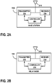
FIG. 2A is a block diagram of an example of the base station shown in FIG. 1.
FIG. 2B is a block diagram of an example of the relay node shown in FIG. 1.
FIG. 2C is a block diagram of an example of the UE devices shown in FIG. 1.
FIG. 2D is a block diagram of an example of the circuitry utilized within the relay node shown in FIG. 1.
FIG. 3 is a messaging diagram of an example of the messages exchanged between the relay node and UE devices when determining a predetermined number of repetitions to transmit the broadcast transmission to the UE devices.
FIG. 4 is a block diagram of an example of a data packet with embedded feedback process information.
FIG. 5 is a messaging diagram of an example of the messages exchanged between the relay node and UE devices when utilizing a default predetermined number of repetitions to transmit the broadcast transmission to the UE devices.
FIG. 6 is a flowchart of an example of a method in which a relay node uses control information to extract, from a block of data, a data stream for each of a plurality of UE devices and transmits, to the plurality of UE devices via a broadcast transmission, the data stream for each of the plurality of UE devices.
FIG. 7 is a flowchart of an example of a method in which a relay node repeatedly transmits, for a predetermined number of repetitions, a broadcast transmission to a plurality of UE devices. The broadcast transmission includes a data stream for each of the plurality of UE devices.
FIG. 8 is a flowchart of an example of a method in which a relay node transmits control information to a plurality of UE devices and transmits, to the plurality of UE devices via a broadcast transmission, a data stream for each of the plurality of UE devices.
FIG. 9 is a flowchart of an example of a method in which a relay node transmits a broadcast transmission to a plurality of UE devices and receives a feedback message from each of the plurality of UE devices regarding their respective data streams.
DETAILED DESCRIPTION
The examples described herein utilize a Multiuser Broadcast Transmission (MBT) to serve the IoT devices. For example, a small cell node (e.g., relay node) uses MBT to transmit data to the IoT devices that are out of the reach of a macrocell node (e.g., base station). The MBT is a single broadcast transmission to a plurality of user equipment (UE) devices that contains data for each of the plurality of UE devices.
The MBT advantageously reduces the amount of control signaling required since the relay node does not, in some examples, utilize any channel-aware scheduling or channel quality feedback from the UE devices for the downlink transmissions. The reduced amount of control signaling and scheduler complexity results in a low-cost solution for both the small cell transmitter (e.g., relay node transmitter) and the UE device receivers. The small cell node performs Long-Term Evolution (LTE) Release-8 paging and IDLE mode procedures for the IoT UE devices such as transmitting the primary synchronization signal (PSS) and secondary synchronization signal (SSS) channels, physical broadcast shared channel (PBSCH), Paging, and System Information Block (SIB) messaging.
In other examples, a UE device may act as a relay node for other UE devices. The network (e.g., base station) may select the UE device that acts as the relay node, or the UE device may volunteer to act as the relay node for other UE devices.
In still other examples, dual-connectivity (DC) could be used with the macrocell base station as the primary cell and the small cell node as the secondary cell. In the DC example, the macrocell node (e.g., base station) handles the basic paging and IDLE mode operations, and when ready, the UE devices switch to CONNECTED mode to transmit/receive data on the secondary cell, which is provided by the small cell node. Although MBT is feasible in the DC mode, the majority of the examples described herein will refer to the small cell node as the relay node.
FIG. 1 is a block diagram of a communication system for an example in which a relay node is used to broadcast data streams to a plurality of user equipment (UE) devices. Communication system 100 is part of a radio access network (not shown) that provides various wireless services to UE devices that are located within the respective service areas of the various base stations that are part of the radio access network. For the examples herein, communication system 100 operates in accordance with at least one revision of the 3rd Generation Partnership Project Long Term Evolution (3GPP LTE) communication specification.
In the interest of clarity and brevity, communication system 100 is shown as having only base station 102. However, in other examples, communication system 100 could have any suitable number of base stations. Base station 102, sometimes referred to as eNodeB or eNB, communicates with user equipment (UE) devices 106, 108, 110 via relay node 104. For example, base station 102 transmits data to relay node 104 via downlink signal 112, and relay node 104 broadcasts the data to UE devices 106, 108, 110 via signal 114. UE devices 106, 108, 110 are any wireless communication devices such as a mobile phone, a transceiver modem, a personal digital assistant (PDA), or a tablet, for example. Although not explicitly shown in FIG. 1, base station 102 may also receive uplink signals from relay node 104 and/or from UE devices 106, 108, 110.
Base station 102 is connected to the network through a backhaul (not shown) in accordance with known techniques. As shown in FIG. 2A, base station 102 comprises controller 204, transmitter 206, and receiver 208, as well as other electronics, hardware, and code. Base station 102 is any fixed, mobile, or portable equipment that performs the functions described herein. The various functions and operations of the blocks described with reference to base station 102 may be implemented in any number of devices, circuits, or elements. Two or more of the functional blocks may be integrated in a single device, and the functions described as performed in any single device may be implemented over several devices.
For the example shown in FIG. 2A, base station 102 may be a fixed device or apparatus that is installed at a particular location at the time of system deployment. Examples of such equipment include fixed base stations or fixed transceiver stations. In some situations, base station 102 may be mobile equipment that is temporarily installed at a particular location. Some examples of such equipment include mobile transceiver stations that may include power generating equipment such as electric generators, solar panels, and/or batteries. Larger and heavier versions of such equipment may be transported by trailer. In still other situations, base station 102 may be a portable device that is not fixed to any particular location. Accordingly, base station 102 may be a portable user device such as a UE device in some circumstances.
Controller 204 includes any combination of hardware, software, and/or firmware for executing the functions described herein as well as facilitating the overall functionality of base station 102. An example of a suitable controller 204 includes code running on a microprocessor or processor arrangement connected to memory. Transmitter 206 includes electronics configured to transmit wireless signals. In some situations, transmitter 206 may include multiple transmitters. Receiver 208 includes electronics configured to receive wireless signals. In some situations, receiver 208 may include multiple receivers. Receiver 208 and transmitter 206 receive and transmit signals, respectively, through antenna 210. Antenna 210 may include separate transmit and receive antennas. In some circumstances, antenna 210 may include multiple transmit and receive antennas.
Transmitter 206 and receiver 208 in the example of FIG. 2A perform radio frequency (RF) processing including modulation and demodulation. Receiver 208, therefore, may include components such as low noise amplifiers (LNAs) and filters. Transmitter 206 may include filters and amplifiers. Other components may include isolators, matching circuits, and other RF components. These components in combination or cooperation with other components perform the base station functions. The required components may depend on the particular functionality required by the base station.
Transmitter 206 includes a modulator (not shown), and receiver 208 includes a demodulator (not shown). The modulator modulates the signals to be transmitted as part of the downlink signal 112 and can apply any one of a plurality of modulation orders. The demodulator demodulates any uplink signals received at base station 102 in accordance with one of a plurality of modulation orders.
As mentioned above, base station 102 provides various wireless services to UE devices 106, 108, 110 via relay node 104. For example, base station 102 transmits data to relay node 104 via downlink signal 112, and relay node 104 broadcasts the data to UE devices 106, 108, 110 via signal 114. The relay node 104 is sometimes referred to as a relay or as a small cell node.
As shown in FIG. 2B, relay node 104 comprises controller 216, transmitter 218, and receiver 214, as well as other electronics, hardware, and code. Relay node 104 is any fixed, mobile, or portable equipment that performs the functions described herein. The various functions and operations of the blocks described with reference to relay node 104 may be implemented in any number of devices, circuits, or elements. Two or more of the functional blocks may be integrated in a single device, and the functions described as performed in any single device may be implemented over several devices.
For the example shown in FIG. 2B, relay node 104 may be a fixed device or apparatus that is installed at a particular location at the time of system deployment. Examples of such equipment include fixed base stations or fixed transceiver stations. In some situations, relay node 104 may be mobile equipment that is temporarily installed at a particular location. Some examples of such equipment include mobile transceiver stations that may include power generating equipment such as electric generators, solar panels, and/or batteries. Larger and heavier versions of such equipment may be transported by trailer. In still other situations, relay node 104 may be a portable device that is not fixed to any particular location. Accordingly, relay node 104 may be a portable user device such as a UE device in some circumstances.
Controller 216 includes any combination of hardware, software, and/or firmware for executing the functions described herein as well as facilitating the overall functionality of relay node 104. An example of a suitable controller 216 includes code running on a microprocessor or processor arrangement connected to memory. Transmitter 218 includes electronics configured to transmit wireless signals. In some situations, transmitter 218 may include multiple transmitters. Receiver 214 includes electronics configured to receive wireless signals. In some situations, receiver 214 may include multiple receivers. Receiver 214 and transmitter 218 receive and transmit signals, respectively, through antenna 212. Antenna 212 may include separate transmit and receive antennas. In some circumstances, antenna 212 may include multiple transmit and receive antennas.
Transmitter 218 and receiver 214 in the example of FIG. 2B perform radio frequency (RF) processing including modulation and demodulation. Receiver 214, therefore, may include components such as low noise amplifiers (LNAs) and filters. Transmitter 218 may include filters and amplifiers. Other components may include isolators, matching circuits, and other RF components. These components in combination or cooperation with other components perform the base station functions. The required components may depend on the particular functionality required by the base station.
Transmitter 218 includes a modulator (not shown), and receiver 214 includes a demodulator (not shown). The modulator modulates the signals to be transmitted as part of the broadcast signal 114 and can apply any one of a plurality of modulation orders. The demodulator demodulates any uplink signals received at relay node 104 in accordance with one of a plurality of modulation orders.
As shown in FIG. 2C, UE devices 106, 108, 110 utilize their respective antennas 220 and receivers 222 to receive downlink signals 114 from relay node 104. Besides antenna 220 and receiver 222, UE device 106 (UE1) further comprises controller 224 and transmitter 226, as well as other electronics, hardware, and code. Although FIG. 2C specifically depicts the circuitry and configuration of UE device 106, the same UE device circuitry and configuration is utilized for UE devices 108, 110 in communication system 100. UE device 106 is any fixed, mobile, or portable equipment that performs the functions described herein. The various functions and operations of the blocks described with reference to UE device 106 may be implemented in any number of devices, circuits, or elements. Two or more of the functional blocks may be integrated in a single device, and the functions described as performed in any single device may be implemented over several devices.
Controller 224 includes any combination of hardware, software, and/or firmware for executing the functions described herein as well as facilitating the overall functionality of a UE device. An example of a suitable controller 224 includes code running on a microprocessor or processor arrangement connected to memory. Transmitter 226 includes electronics configured to transmit wireless signals. In some situations, the transmitter 226 may include multiple transmitters. Receiver 222 includes electronics configured to receive wireless signals. In some situations, receiver 222 may include multiple receivers. Receiver 222 and transmitter 226 receive and transmit signals, respectively, through antenna 220. Antenna 220 may include separate transmit and receive antennas. In some circumstances, antenna 220 may include multiple transmit and receive antennas.
Transmitter 226 and receiver 222 in the example of FIG. 2C perform radio frequency (RF) processing including modulation and demodulation. Receiver 222, therefore, may include components such as low noise amplifiers (LNAs) and filters. Transmitter 226 may include filters and amplifiers. Other components may include isolators, matching circuits, and other RF components. These components in combination or cooperation with other components perform the UE device functions. The required components may depend on the particular functionality required by the UE device.
Transmitter 226 includes a modulator (not shown), and receiver 222 includes a demodulator (not shown). The modulator can apply any one of a plurality of modulation orders to modulate the signals to be transmitted as uplink signals (not shown). The demodulator demodulates the downlink signals 114 in accordance with one of a plurality of modulation orders.
In operation, base station 102 transmits, via transmitter 206 and antenna 210, downlink signal 112 to relay node 104. Downlink signal 112 contains control information and a block of data assigned to UE devices 106, 108, 110. In the example shown in FIG. 1, the block of data includes data intended for UE devices 106, 108, 110 that is multiplexed (e.g., combined) together to form a single signal 112. In some examples, the control information is a bitmap.
Relay node 104 receives downlink signal 112 via antenna 212 and receiver 214. The control information helps relay node 104 identify UE devices 106, 108, 110 and match them to their respective data streams. More specifically, relay node 104 uses the control information to (1) extract the data stream for each of UE devices 106, 108, 110 from the block of data contained in downlink signal 112, and (2) assign each data stream to a narrowband channel, resulting in a frequency-division multiplexing (FDM)-based resource allocation.
For example, as shown in FIG. 2D, relay node 104 includes demultiplexer 228, which is used in combination with receiver 214 of relay node 104 and the control information received from base station 102, to (1) separate the multiplexed block of data contained in downlink signal 112 into separate data streams intended for each of UE devices 106, 108, 110, and (2) match each of the separated (e.g. extracted) data streams to a particular UE device. As shown in FIG. 2D, the product of demultiplexer 228 is first data stream 230 that is matched to UE1 106, second data stream 232 that is matched to UE2 108, and third data stream 234 that is matched to UE3 110. The functionality of demultiplexer 228 is performed by controller 216 in the example shown in FIG. 2D. However, in other examples, the functionality of demultiplexer 228 may be performed by any other suitable circuitry.
The separated data streams 230, 232, 234 are sent to resource mapper 236, which maps (e.g., assigns) each of the separated data streams 230, 232, 234 to a narrowband channel. In order to serve UE devices 106, 108, 110, relay node 104 splits the downlink bandwidth of signal 114 into a number of narrowband channels, for example, each consisting of six resource blocks in the frequency domain, as specified in LTE-Machine Type Communication (LTE-M) Release-12. In some examples, space-division multiplexing (SDM) and/or frequency-hopping schemes on top of FDM can be applied to each narrowband signal. In other examples, time-division multiplexing (TDM) or code-division multiplexing (CDM) may be used instead of SDM. At the physical layer level, each UE-specific narrowband channel is allocated (e.g., assigned) a set of subcarriers within the portion of downlink channel bandwidth.
Relay node 104 transmits, via transmitter 218 and antenna 212, control information to UE devices 106, 108, 110, which are configured to use the control information to receive their respective data streams. In the examples described herein, there are two methods to deliver the downlink control information (DCI) to UE devices 106, 108, 110. The DCI parameters common to all UE devices 106, 108, 110 are delivered using the Common Search Space Machine-Type Communication Physical Downlink Control Channel (CSS-MPDCCH) or SIB messaging. The second method is to send the DCI using the UE-specific search space (USS) MPDCCH or to embed the DCI within a data packet in broadcast transmission 114.
The resource allocation (e.g., assignment) information, the modulation and coding scheme (MCS), and the transmission mode information for the multiuser broadcast transmission 114 are semi-static and can be announced to all targeted UE devices 106, 108, 110 before beginning data transmission since these parameters are kept the same during the transmission of multiple data blocks. For example, after receiving the block of data from base station 102 and determining Nrep, relay node 104 transmits control information regarding the resource assignment information, the MCS, the Nrep, and the transmission mode information (e.g., transmit diversity parameters, etc.) to UE devices 106, 108, and 110 using the CSS-MPDCCH or SIB messaging.
As mentioned above, the control information transmitted to UE devices 106, 108, 110 may include, for example, one or more of the following: a predetermined number of repetitions (e.g., times) that the broadcast transmission 114 will be transmitted, a modulation and coding scheme, resource allocation (e.g., assignment) information, transmission mode information, and feedback process information. In some examples, the control information is transmitted in a System Information Block (SIB) message. In other examples, the control information is transmitted on a Common Search Space Machine-Type Communication Physical Downlink Control Channel (CSS-MPDCCH). For example, UE devices 106, 108, 110 are informed about the resource assignment information (e.g., which narrowband channel contains the data stream for which UE device and/or which subcarriers are associated with each narrowband channel) via control information signaling (e.g. MPDCCH).
Once UE devices 106, 108, 110 are informed about the resource assignment information and/or other control information, relay node 104 transmits a broadcast transmission 114 to UE devices 106, 108, 110 via transmitter 218 and antenna 212. The broadcast transmission 114 contains the data stream for each of UE devices 106, 108, 110 in a separate narrowband channel. Although each of UE devices 106, 108, 110 will receive the same multiuser broadcast transmission (MBT) 114 from relay node 104, each UE device 106, 108, 110 will use its own respective narrowband receiver, which may be integrated into receiver 222, to access (e.g., receive and decode) the portion of the received downlink signal 114 that contains the narrowband channel that has been assigned to that particular UE device.
To achieve robustness, relay node 104 transmits broadcast transmission 114 for a predetermined number of repetitions using multi-subframe repetition, as defined in LTE-M Release-12. In IoT deployments, the data is repeatedly transmitted over multiple subframes to achieve robustness at the expense of higher latency. In some examples, the predetermined number of repetitions is a default number of repetitions. In other examples, the predetermined number of repetitions is determined.
FIG. 3 is a messaging diagram of an example of the messages exchanged between relay node 104 and UE devices 106, 108, 110 when determining a predetermined number of repetitions, Nrep, to transmit broadcast transmission 114 to UE devices 106, 108, 110. In some examples, the predetermined number of repetitions, Nrep, is computed based on the worst received signal strength reported by UE devices 106, 108, 110. As shown in FIG. 3, relay node 104 transmits, via transmitter 218 and antenna 212, paging message 302 to all UE devices 106, 108, 110 listed in the block of data received from base station 102. In the example shown in FIG. 3, relay node 104 uses the common search space (CSS) MPDCCH to page UE devices 106, 108, 110. In other examples, the UE devices 106, 108, 110 periodically monitor the downlink signal 114 and may receive data at a predetermined subframe (e.g., in polling scheduler deployments).
In some examples, paging message 302 includes a request for UE devices 106, 108, 110 to each submit downlink measurement reports to relay node 104, based on their respectively measured received signal strength of broadcast transmission 114. In other examples, paging message 302 includes a request for UE devices 106, 108, 110 to each submit downlink measurement reports to relay node 104, if their received signal strength measurement value γ, is below a threshold value γt. In response to paging message 302, one or more of UE devices 106, 108, 110 transmit their respective page response 304 using their assigned Physical Uplink Control Channel (PUCCH) resources.
In some examples, one or more of the page responses 304 may include a downlink measurement report. In order to obtain exactness in some examples, UE devices 106, 108, 110 include a quantized worseness of the received signal strength compared to one or more threshold values, γt, in the downlink measurement report. For example, if a UE device is experiencing received signal strength below a first threshold value, γt1, then the UE device reports back a threshold index value of ‘1’, and if the received signal strength is below first and second threshold values, γt1 and γt2, then the UE device reports a threshold index value of ‘2’ and so on. Alternatively, if a UE device is experiencing received signal strength up to 0.5 dB (e.g., within a first range) below γt, then the UE device reports back a range index value of ‘1’, and if the received signal strength is between 1 dB and 0.5 dB (e.g., within a second range) below γt, then the UE device reports a range index value of ‘2’ and so on.
Thus, in light of the foregoing, the downlink measurement report may include one or more of the following: a received signal strength measurement value, γ; a first threshold index value that indicates that a received signal strength measurement value, γ, is below a first threshold value; a second threshold index value that indicates that a received signal strength measurement value, γ, is below a first threshold value and a second threshold value; a first range index value that indicates that a received signal strength measurement value, γ, is within a first range of values below a first threshold value; and a second range index value that indicates that a received signal strength measurement value, γ, is within a second range of values below a first threshold value.
Based on the number of UE devices 106, 108, 110 that report back the condition γ<γt and their reported index value, relay node 104 utilizes controller 216 to determine the value of Nrep. With this approach, the value of Nrep becomes a function of the number of UE devices 106, 108, 110 reporting γ<γt and their respective reported index values.
After the value of Nrep is decided (e.g., by default or determined by relay node 104), relay node 104 transmits control information 306 to be used for the multiuser broadcast transmissions 114 to all UE devices 106, 108, 110. As mentioned above, this control information 306 may include, for example, one or more of the following: a predetermined number of repetitions (e.g., Nrep) that the broadcast transmission 114 will be transmitted, a modulation and coding scheme, resource allocation (e.g., assignment) information, transmission mode information, and feedback process information. In some examples, the control information is transmitted in a System Information Block (SIB) message. In other examples, the control information is transmitted on a Common Search Space Machine-Type Communication Physical Downlink Control Channel (CSS-MPDCCH). In still other examples, the control information is transmitted in a data packet of broadcast transmission 114. In further examples, the control information is transmitted on a UE-specific Search Space Machine-Type Communication Physical Downlink Control Channel (USS-MPDCCH). The resource allocation information and the value of Nrep can be transmitted semi-statically to UE devices 106, 108, 110 and are not required to be transmitted again until there is a change in the resource allocation or the predetermined number of repetitions.
Regardless of the manner in which the predetermined number of repetitions is determined, relay node 104 transmits, via transmitter 218 and antenna 212, broadcast transmission 114 (e.g., signal 308) for the predetermined number of repetitions, Nrep. UE devices 106, 108, 110 utilize the control information 306 to receive the repeated broadcast transmissions 114 and combine the energy received in each subframe to achieve a higher energy per bit, resulting in a higher successful detection rate. After receiving all Nrep subframes of data, each UE device 106, 108, 110 transmits feedback message 310 to relay node 104 using a Physical Uplink Control Channel (PUCCH) or a Physical Uplink Shared Channel (PUSCH). Relay node 104 receives feedback message 310 via antenna 212 and receiver 214. In the example shown in FIG. 3, feedback message 310 is either an ACK or a NACK signal.
In some examples, Hybrid Automatic Repeat Request (HARQ) feedback is used in connection with the multiuser broadcast transmissions 114 to achieve higher detection performance. To handle the HARQ processes assigned to a particular UE device, HARQ process information 404 such as a HARQ Process Identifier (ID) (HPI), a New Data Indicator (NDI), and a Redundancy Version (RV) is embedded in the data packet 402 itself, as shown in FIG. 4. After receiving the narrowband channel data packet, each UE device 106, 108, 110 decodes the HARQ process information 404 before decoding the data in the data packet 402. This allows each UE device 106, 108, 110 to monitor and track its own respective HARQ process information.
In some examples, the UE device waits to receive all the repetitions (e.g., Nrep) of the broadcast transmission 114 before attempting to decode the packet. In other examples, the UE device may attempt to decode the packet after receiving any number of repetitions or after receiving each repetition. Depending on the decoding success, the UE device sends either an ACK or a NACK feedback message to relay node 104. If the UE device is successfully able to decode the packet before receiving all of the repetitions, the UE device could send an early termination ACK. If the feedback message is an ACK, relay node 104 transmits a new data packet (and a New Data Indicator) in the next transmission. If the feedback message is a NACK, relay node 104 transmits a next Redundancy Version packet (and an associated Redundancy Version (RV) value) in the next transmission. As a consequence of using this HARQ process for different UE devices 106, 108, 110 within the same multiuser broadcast transmission 114, the RV of the data packets addressed to different UE devices 106, 108, 110 could be different. Thus, relay node 104 is responsible for managing the HARQ processes for each of UE devices 106, 108, 110.
Since multiple UE devices 106, 108, 110 are served with the multiuser broadcast transmission 114, the PUCCH capacity may not be enough to transmit the large number of ACK/NACK feedback messages. Thus, in some examples, UE devices 106, 108, 110 are allowed to transmit their ACK/NACK feedback messages on PUSCH resources. In some examples, the amount of feedback signaling can be reduced if the UE devices 106, 108, 110 only transmit a NACK if they are unable to decode the data packet after receiving all of the repetitions (e.g., Nrep).
FIG. 5 shows the signaling flows when a default MCS and a default Nrep are used for the multiuser broadcast transmission 114. The use of a default MCS and a default Nrep for the multiuser broadcast transmission 114 reduces the amount of control signaling required. For example, relay node 104 announces the default MCS value and the default Nrep value periodically to all UE devices 106, 108, 110 using SIB messaging (e.g., control information 502). After the block of data is received from base station 102, relay node 104 allocates (e.g., assigns) the narrowband channels to UE devices 106, 108, 110 and transmits those assignments to the respective UE devices 106, 108, 110 in the page messages 504 transmitted to UE devices 106, 108, 110. UE devices 106, 108, 110 transmit page responses 506 on granted PUSCH resources. In other examples, the page messages 504 are not required if UE devices 106, 108, 110 are already periodically scheduled (e.g., by a polling scheduler) to monitor the data channel 114 to receive the narrowband channel assignments.
Relay node 104 transmits broadcast transmission 508 for the default number of repetitions, Nrep. UE devices 106, 108, 110 transmit feedback messages 514 to relay node 104 on granted PUSCH resources. Based on the received feedback messages 514, relay node 104 places either a new data packet or a next Redundancy Version packet on the assigned narrowband channel for each UE device 106, 108, 110. Unless one or more UE devices 106, 108, 110 report back a worse channel condition γ<γt, relay node 104 avoids transmitting the MPDCCH. The MPDCCH is only transmitted to provide the new non-default values of the MCS and/or Nrep.
There are several advantages to the examples described herein. For example, as mentioned above, the examples described herein do not require a complex channel-aware scheduler and do not require frequent individual Channel State Information (CSI) feedback from the UE devices 106, 108, 110. This significantly reduces the complexity of relay node 104 and reduces the control signaling overhead. In addition, the multiuser broadcast transmissions 114 from the near-located relay node 104 allow for a reduced number of required repetitions, Nrep, achieving further efficiency.
FIG. 6 is a flowchart of an example of a method in which a relay node uses control information to extract, from a block of data, a data stream for each of a plurality of UE devices and transmits, to the plurality of UE devices via a broadcast transmission, the data stream for each of the plurality of UE devices. The method 600 begins at step 602 with receiving, at relay node 104, a block of data and control information. At step 604, relay node 104 uses the control information to extract a data stream, from the block of data, for each of UE devices 106, 108, 110. At step 606, relay node 104 assigns each data stream to one of a plurality of narrowband channels. At step 608, relay node 104 allocates a set of subcarriers to each of the plurality of narrowband channels. At step 610, relay node 104 transmits, to UE devices 106, 108, 110, resource assignment information. At step 612, relay node 104 transmits, to UE devices 106, 108, 110, a paging message. At step 614, relay node 104 transmits, to UE devices 106, 108, 110 via a broadcast transmission 114, the data stream for each of UE devices 106, 108, 110.
FIG. 7 is a flowchart of an example of a method in which a relay node repeatedly transmits, for a predetermined number of repetitions, a broadcast transmission to a plurality of UE devices. The broadcast transmission includes a data stream for each of the plurality of UE devices. The method 700 begins at step 702 with transmitting control information from relay node 104 to UE devices 106, 108, 110. At step 704, relay node 104 transmits a paging message to UE devices 106, 108, 110. At step 706, relay node 104 receives at least one downlink measurement report from at least one of UE devices 106, 108, 110. At step 708, relay node 104 determines a predetermined number of repetitions based on at least one downlink measurement report. At step 710, relay node 104 repeatedly transmits, for the predetermined number of repetitions, a broadcast transmission 114 to UE devices 106, 108, 110. The broadcast transmission 114 includes a data stream for each of UE devices 106, 108, 110.
FIG. 8 is a flowchart of an example of a method in which a relay node transmits control information to a plurality of UE devices and transmits, to the plurality of UE devices via a broadcast transmission, a data stream for each of the plurality of UE devices. The method 800 begins at step 802 with receiving, at relay node 104, a block of data containing a data stream for each of UE devices 106, 108, 110. At step 804, relay node 104 assigns each data stream to one of a plurality of narrowband channels. At step 806, relay node 104 allocates a set of subcarriers to each of the plurality of narrowband channels. At step 808, relay node 104 transmits control information to UE devices 106, 108, 110. At step 810, relay node 104 transmits a broadcast transmission 114 to UE devices 106, 108, 110. The broadcast transmission 114 includes a data stream for each of UE devices 106, 108, 110.
FIG. 9 is a flowchart of an example of a method in which a relay node transmits a broadcast transmission to a plurality of UE devices and receives a feedback message from each of the plurality of UE devices regarding their respective data streams. The method 900 begins at step 902 with transmitting control information from relay node 104 to UE devices 106, 108, 110. At step 904, relay node 104 transmits a broadcast transmission 114 to UE devices 106, 108, 110. The broadcast transmission 114 includes a data stream for each of UE devices 106, 108, 110. At step 906, relay node 104 receives a feedback message from each of UE devices 106, 108, 110 regarding their respective data streams. At step 908, if the feedback message is an ACK signal, relay node 104 transmits a new data packet in the next transmission to the UE device that sent the ACK signal. At step 910, if the feedback message is a NACK signal, relay node 104 transmits a next Redundancy Version data packet in the next transmission to the UE device that sent the NACK signal.
Clearly, other embodiments and modifications of this invention will occur readily to those of ordinary skill in the art in view of these teachings. The above description is illustrative and not restrictive. This invention is to be limited only by the following claims, which include all such embodiments and modifications when viewed in conjunction with the above specification and accompanying drawings. The scope of the invention should, therefore, be determined not with reference to the above description, but instead should be determined with reference to the appended claims along with their full scope of equivalents.

Claims (22)

The invention claimed is:
1. A method comprising:
receiving, at a relay node from a base station, a block of data comprising a plurality of multiplexed data streams, each data stream intended to be received by one of a plurality of user equipment (UE) devices being served by the relay node;
extracting each of the plurality of data streams from the block of data received at the relay node;
transmitting control information from the relay node to the plurality of UE devices;
transmitting a broadcast transmission from the relay node to the plurality of UE devices, the broadcast transmission comprising the plurality of data streams extracted from the block of data, each of the plurality of UE devices configured to apply the control information to attempt to receive the data stream intended to be received by the UE device; and
receiving a feedback message from each of the plurality of UE devices, each feedback message regarding the attempt to receive the data stream intended to be received by the UE device.
2. The method of claim 1, wherein transmitting control information comprises at least one of the following: transmitting control information in a data packet of the broadcast transmission, and transmitting control information on a UE-specific Search Space Machine-Type Communication Physical Downlink Control Channel (USS-MPDCCH).
3. The method of claim 2, wherein the control information comprises at least one of the following: a Hybrid Automatic Repeat Request (HARQ) Process Identifier (ID) (HPI), a New Data Indicator (NDI), and a Redundancy Version (RV).
4. The method of claim 1, wherein receiving the feedback message from each of the plurality of UE devices comprises receiving the feedback message from each of the plurality of UE devices via a Physical Uplink Shared Channel (PUSCH).
5. The method of claim 1, wherein a feedback message received from a first one of the plurality of UE devices comprises an acknowledgement (ACK) signal.
6. The method of claim 5, further comprising:
transmitting a new data packet to the first one of the plurality of UE devices in a next transmission.
7. The method of claim 1, wherein a feedback message received from a first one of the plurality of UE devices comprises a negative-acknowledgement (NACK) signal.
8. The method of claim 7, further comprising:
transmitting a next Redundancy Version data packet to the first one of the plurality of UE devices in a next transmission.
9. The method of claim 1, further comprising:
receiving, at the relay node from the base station, base station control information and applying the base station control information to extract the data streams from the block of data.
10. The method of claim 9, wherein the broadcast transmission comprises a plurality of narrowband channels such that each data stream, of the plurality of data streams, is transmitted in a different narrowband channel of the plurality of narrowband channels.
11. A relay node comprising:
a receiver configured to receive, from a base station, a block of data comprising a plurality of multiplexed data streams, each data stream intended to be received by one of a plurality of user equipment (UE) devices being served by the relay node, the receiver configured to extract each of the plurality of data streams from the block of data received at the relay node; and
a transmitter configured to:
transmit control information to the plurality of UE devices, and
transmit a broadcast transmission to the plurality of UE devices, the broadcast transmission comprising the plurality of data streams extracted from the block of data, each of the plurality of UE devices configured to apply the control information to attempt to receive the data stream intended to be received by the UE device,
the receiver further configured to receive a feedback message from each of the plurality of UE devices, each feedback message regarding the attempt to receive the data stream intended to be received by the UE device.
12. The relay node of claim 11, wherein the transmitter is further configured to transmit control information in a data packet of the broadcast transmission.
13. The relay node of claim 12, wherein the control information comprises at least one of the following: a Hybrid Automatic Repeat Request (HARQ) Process Identifier (ID) (HPI), a New Data Indicator (NDI), and a Redundancy Version (RV).
14. The relay node of claim 11, wherein the transmitter is further configured to transmit control information on a UE-specific Search Space Machine-Type Communication Physical Downlink Control Channel (USS-MPDCCH).
15. The relay node of claim 14, wherein the control information comprises at least one of the following: a Hybrid Automatic Repeat Request (HARQ) Process Identifier (ID) (HPI), a New Data Indicator (NDI), and a Redundancy Version (RV).
16. The relay node of claim 11, wherein the receiver is further configured to receive the feedback message from each of the plurality of UE devices via a Physical Uplink Shared Channel (PUSCH).
17. The relay node of claim 11, wherein a feedback message received from a first one of the plurality of UE devices comprises an acknowledgement (ACK) signal.
18. The relay node of claim 17, wherein the transmitter is further configured to transmit a new data packet to the first one of the plurality of UE devices in a next transmission.
19. The relay node of claim 11, wherein a feedback message received from a first one of the plurality of UE devices comprises a negative-acknowledgement (NACK) signal.
20. The relay node of claim 19, wherein the transmitter is further configured to transmit a next Redundancy Version data packet to the first one of the plurality of UE devices in a next transmission.
21. The relay node of claim 11, the receiver further configured to receive, from the base station, base station control information and apply the base station control information to extract the data streams from the block of data.
22. The relay node of claim 21, wherein the broadcast transmission comprises a plurality of narrowband channels such that each data stream, of the plurality of data streams, is transmitted in a different narrowband channel of the plurality of narrowband channels.
US17/040,838 2018-04-23 2019-04-23 HARQ process for multiuser broadcast transmission node Active 2039-07-16 US11388697B2 (en)

Priority Applications (1)

Application Number Priority Date Filing Date Title
US17/040,838 US11388697B2 (en) 2018-04-23 2019-04-23 HARQ process for multiuser broadcast transmission node

Applications Claiming Priority (6)

Application Number Priority Date Filing Date Title
US201862661253P 2018-04-23 2018-04-23
US201862682081P 2018-06-07 2018-06-07
US201862682090P 2018-06-07 2018-06-07
US201862682095P 2018-06-07 2018-06-07
US17/040,838 US11388697B2 (en) 2018-04-23 2019-04-23 HARQ process for multiuser broadcast transmission node
PCT/US2019/028642 WO2019209783A1 (en) 2018-04-23 2019-04-23 Harq process for multiuser broadcast transmission node

Publications (2)

Publication Number Publication Date
US20210022114A1 US20210022114A1 (en) 2021-01-21
US11388697B2 true US11388697B2 (en) 2022-07-12

Family

ID=68293587

Family Applications (5)

Application Number Title Priority Date Filing Date
US17/040,804 Active 2039-05-27 US11356978B2 (en) 2018-04-23 2019-04-23 Multiuser broadcast transmission node
US17/040,838 Active 2039-07-16 US11388697B2 (en) 2018-04-23 2019-04-23 HARQ process for multiuser broadcast transmission node
US17/040,759 Active US11337179B2 (en) 2018-04-23 2019-04-23 Control information from macrocell to node, mapping data blocks to UE ID
US17/040,718 Active 2039-10-23 US11558851B2 (en) 2018-04-23 2019-04-23 Broadcast transmission by relay node
US17/040,873 Active 2039-07-01 US11425686B2 (en) 2018-04-23 2019-04-23 Method of determining number of repetitions for multiuser broadcast in IoT deployments

Family Applications Before (1)

Application Number Title Priority Date Filing Date
US17/040,804 Active 2039-05-27 US11356978B2 (en) 2018-04-23 2019-04-23 Multiuser broadcast transmission node

Family Applications After (3)

Application Number Title Priority Date Filing Date
US17/040,759 Active US11337179B2 (en) 2018-04-23 2019-04-23 Control information from macrocell to node, mapping data blocks to UE ID
US17/040,718 Active 2039-10-23 US11558851B2 (en) 2018-04-23 2019-04-23 Broadcast transmission by relay node
US17/040,873 Active 2039-07-01 US11425686B2 (en) 2018-04-23 2019-04-23 Method of determining number of repetitions for multiuser broadcast in IoT deployments

Country Status (2)

Country Link
US (5) US11356978B2 (en)
WO (5) WO2019209780A1 (en)

Families Citing this family (6)

* Cited by examiner, † Cited by third party
Publication number Priority date Publication date Assignee Title
KR102165806B1 (en) * 2018-08-16 2020-10-14 에스케이텔레콤 주식회사 Transmission device and control method thereof
US11477760B2 (en) * 2019-12-19 2022-10-18 Qualcomm Incorporated Frequency diversity techniques for single frequency networks
US11792824B2 (en) * 2020-03-30 2023-10-17 Qualcomm Incorporated Multicast feedback and retransmission for transport block grouping
US20220069893A1 (en) * 2020-08-25 2022-03-03 Qualcomm Incorporated Autonomous acquisition of configuration information in radio frequency repeaters
WO2022077265A1 (en) * 2020-10-14 2022-04-21 北京小米移动软件有限公司 Transmission configuration method, transmission configuration apparatus and storage medium
US20230051415A1 (en) * 2021-08-12 2023-02-16 Qualcomm Incorporated Bandwidth part switching in repeaters

Citations (15)

* Cited by examiner, † Cited by third party
Publication number Priority date Publication date Assignee Title
US20120099553A1 (en) * 2009-06-18 2012-04-26 Tatsushi Aiba Mobile communication system, base station apparatus, mobile station apparatus, and mobile communication method
US20120300692A1 (en) * 2009-10-22 2012-11-29 Interdigital Patent Holdings, Inc. Method and apparatus for a two-way relaying scheme with physical layer network coding
US20130170424A1 (en) * 2011-12-29 2013-07-04 Qualcomm Incorporated Selectively multiplexing communication streams
US20130279447A1 (en) * 2010-07-09 2013-10-24 Lg Electronics Inc. Method and apparatus for transmitting uplink reference signal in a multi-antenna wireless communication system
US20130315196A1 (en) * 2011-02-15 2013-11-28 Lg Electronics Inc. Hybrid automatic repeat request (harq) method and device in a cooperative terminal communication system
US20150063247A1 (en) * 2012-04-18 2015-03-05 Lg Electronics Inc. Method for performing harq for device-to-device communication in wireless communication system and device for same
US20160135143A1 (en) * 2014-11-07 2016-05-12 Samsung Electronics Co., Ltd. Method and apparatus for transmitting group message to user equipment (ue)
US20160309282A1 (en) * 2015-04-20 2016-10-20 Qualcomm Incorporated Control channel based broadcast messaging
WO2017030520A1 (en) 2015-08-20 2017-02-23 Intel IP Corporation Machine type communication relaying
US20180020493A1 (en) * 2016-07-14 2018-01-18 Sprint Communications Company L.P. General packet radio service tunneling protocol multiplexing
US20180263026A1 (en) * 2015-11-06 2018-09-13 Sun Patent Trust Multiple sidelink control transmissions during a sidelink control period
US20190215101A1 (en) * 2017-11-17 2019-07-11 Lg Electronics Inc. Method of transmitting and receiving system information and device therefor
US20190313386A1 (en) * 2018-04-05 2019-10-10 Lg Electronics Inc. Method of transmitting and receiving downlink data channel and apparatus therefor
US20200213901A1 (en) * 2017-06-15 2020-07-02 Sharp Kabushiki Kaisha Base station apparatus, terminal apparatus, and communication method for these apparatuses
US20200295903A1 (en) * 2017-10-02 2020-09-17 Telefonaktiebolaget Lm Ericsson (Publ) Pucch resource indication for csi and harq feedback

Family Cites Families (32)

* Cited by examiner, † Cited by third party
Publication number Priority date Publication date Assignee Title
US7508804B2 (en) * 2002-04-05 2009-03-24 Alcatel-Lucent Usa Inc. Shared signaling for multiple user equipment
WO2007052131A2 (en) * 2005-11-02 2007-05-10 Nokia, Corporation Method for sub-channel assignment in a relay node.
KR101464748B1 (en) 2007-04-30 2014-11-24 엘지전자 주식회사 Method for triggering a measurement report of mobile terminal
US9009573B2 (en) * 2008-02-01 2015-04-14 Qualcomm Incorporated Method and apparatus for facilitating concatenated codes for beacon channels
WO2010044187A1 (en) * 2008-10-15 2010-04-22 パナソニック株式会社 Communication terminal and communication method
KR101424378B1 (en) * 2008-12-26 2014-07-31 후지쯔 가부시끼가이샤 Radio communication system
US8780784B2 (en) * 2009-05-29 2014-07-15 Lg Electronics Inc. Method and apparatus for transmitting control information from relay node on backhaul uplink
US20110170474A1 (en) * 2009-07-15 2011-07-14 Ji Tingfang Method and apparatus for transparent relay hybrid automatic repeat request (harq)
WO2011019960A2 (en) * 2009-08-12 2011-02-17 Research In Motion Limited Physical uplink shared channel demodulation reference signal design for uplink coordinated transmission in type ii relay using a punctured demodulation reference signal
JPWO2011052022A1 (en) * 2009-11-02 2013-03-14 株式会社日立製作所 RADIO COMMUNICATION SYSTEM HAVING RELAY DEVICE AND RELAY TERMINAL SELECTION METHOD
EP2509366B1 (en) * 2009-11-30 2019-10-09 LG Electronics Inc. Terminal device for receiving signal in wireless communication system for supporting a plurality of component carriers and method thereof
US8665768B2 (en) 2010-01-29 2014-03-04 Qualcomm Incorporated Femtocell one-to-many packet delivery
WO2011136524A2 (en) * 2010-04-25 2011-11-03 엘지전자 주식회사 Method and apparatus for transceiving data in a wireless access system
GB2486743B (en) * 2010-12-24 2013-02-13 Nvidia Corp Cellular communication system for broadcast communication
EP2695420B1 (en) * 2011-04-07 2019-08-21 Nokia Solutions and Networks Oy Functional split for a multi-node carrier aggregation transmission scheme
WO2013062357A2 (en) * 2011-10-27 2013-05-02 엘지전자 주식회사 Method for allowing terminal to perform random access step in wireless communication system and device therefor
US9451639B2 (en) * 2013-07-10 2016-09-20 Samsung Electronics Co., Ltd. Method and apparatus for coverage enhancement for a random access process
US10149099B2 (en) * 2014-01-05 2018-12-04 Lg Electronics Inc. Method and user equipment for relaying proximity service-based group communication
US10278120B2 (en) 2014-01-16 2019-04-30 Industry-University Cooperation Foundation Hanyang University Method for controlling small cell and apparatus for same
ES2742039T3 (en) * 2014-01-30 2020-02-12 Alcatel Lucent Communication techniques that use a repeat regime in an enhanced coverage region
JP6539439B2 (en) * 2014-11-14 2019-07-03 Kddi株式会社 RADIO CONTROL DEVICE, TERMINAL DEVICE, AND COMMUNICATION METHOD
US9883485B2 (en) * 2015-01-08 2018-01-30 Qualcomm Incorporated Evolved multimedia broadcast multicast service on enhanced component carriers
US20180116007A1 (en) * 2015-04-09 2018-04-26 Ntt Docomo, Inc. Communication terminal
CN106160931A (en) 2015-04-09 2016-11-23 电信科学技术研究院 A kind of method and device of information transmission
CN108029148B (en) * 2015-07-23 2022-04-01 苹果公司 Mobility relay method and device
WO2017026443A1 (en) * 2015-08-11 2017-02-16 京セラ株式会社 Wireless terminal and base station
WO2017051503A1 (en) * 2015-09-24 2017-03-30 パナソニック インテレクチュアル プロパティ コーポレーション オブ アメリカ Communication system, relay terminal, remote terminal, and communication control method
US10326549B2 (en) 2015-11-06 2019-06-18 Telefonaktiebolaget Lm Ericsson (Publ) CSI reference resource and CQI report for MTC operation
US10581627B1 (en) * 2016-02-02 2020-03-03 Marvell International Ltd. Broadcast and multicast in a wireless communication system in a wireless communication network
WO2017161265A1 (en) 2016-03-18 2017-09-21 Kyocera Corporation System and method for multiuser packets transmissions for relays
EP3229549B1 (en) * 2016-04-08 2018-11-21 Panasonic Intellectual Property Corporation of America Procedures for grouping wearable devices with lte master ues
CN111989959B (en) * 2018-04-04 2021-11-30 华为技术有限公司 Information sending and receiving method and device

Patent Citations (15)

* Cited by examiner, † Cited by third party
Publication number Priority date Publication date Assignee Title
US20120099553A1 (en) * 2009-06-18 2012-04-26 Tatsushi Aiba Mobile communication system, base station apparatus, mobile station apparatus, and mobile communication method
US20120300692A1 (en) * 2009-10-22 2012-11-29 Interdigital Patent Holdings, Inc. Method and apparatus for a two-way relaying scheme with physical layer network coding
US20130279447A1 (en) * 2010-07-09 2013-10-24 Lg Electronics Inc. Method and apparatus for transmitting uplink reference signal in a multi-antenna wireless communication system
US20130315196A1 (en) * 2011-02-15 2013-11-28 Lg Electronics Inc. Hybrid automatic repeat request (harq) method and device in a cooperative terminal communication system
US20130170424A1 (en) * 2011-12-29 2013-07-04 Qualcomm Incorporated Selectively multiplexing communication streams
US20150063247A1 (en) * 2012-04-18 2015-03-05 Lg Electronics Inc. Method for performing harq for device-to-device communication in wireless communication system and device for same
US20160135143A1 (en) * 2014-11-07 2016-05-12 Samsung Electronics Co., Ltd. Method and apparatus for transmitting group message to user equipment (ue)
US20160309282A1 (en) * 2015-04-20 2016-10-20 Qualcomm Incorporated Control channel based broadcast messaging
WO2017030520A1 (en) 2015-08-20 2017-02-23 Intel IP Corporation Machine type communication relaying
US20180263026A1 (en) * 2015-11-06 2018-09-13 Sun Patent Trust Multiple sidelink control transmissions during a sidelink control period
US20180020493A1 (en) * 2016-07-14 2018-01-18 Sprint Communications Company L.P. General packet radio service tunneling protocol multiplexing
US20200213901A1 (en) * 2017-06-15 2020-07-02 Sharp Kabushiki Kaisha Base station apparatus, terminal apparatus, and communication method for these apparatuses
US20200295903A1 (en) * 2017-10-02 2020-09-17 Telefonaktiebolaget Lm Ericsson (Publ) Pucch resource indication for csi and harq feedback
US20190215101A1 (en) * 2017-11-17 2019-07-11 Lg Electronics Inc. Method of transmitting and receiving system information and device therefor
US20190313386A1 (en) * 2018-04-05 2019-10-10 Lg Electronics Inc. Method of transmitting and receiving downlink data channel and apparatus therefor

Also Published As

Publication number Publication date
US20210022114A1 (en) 2021-01-21
US11337179B2 (en) 2022-05-17
US20210007079A1 (en) 2021-01-07
US11558851B2 (en) 2023-01-17
WO2019209778A1 (en) 2019-10-31
WO2019209783A1 (en) 2019-10-31
US11425686B2 (en) 2022-08-23
WO2019209780A1 (en) 2019-10-31
US20210007078A1 (en) 2021-01-07
US11356978B2 (en) 2022-06-07
WO2019209781A1 (en) 2019-10-31
US20210006365A1 (en) 2021-01-07
US20210014829A1 (en) 2021-01-14
WO2019209784A1 (en) 2019-10-31

Similar Documents

Publication Publication Date Title
US11388697B2 (en) HARQ process for multiuser broadcast transmission node
US20170141833A1 (en) Method and device for supporting data communication in wireless communication system
EP4158816B1 (en) Multiplexing multicast and unicast feedback
WO2020069088A4 (en) Improved groupcast and unicast in new radio vehicle-to-everything (v2x) communication
US11863253B2 (en) Type-1 codebook construction with multiple aggregation factors
KR20180022808A (en) Method and apparatus for narrowband signal transmission in wireless cellular communication systems
CN115428385A (en) Signaling for adjusting slot formats
US20240080089A1 (en) System and method for dual-control signaling for the relay scenarios
KR20230069918A (en) Sidelink Feedback Preemption and Uplink Multiplexing in Radios
CN116158165A (en) Semi-persistent scheduling of side link communications
US20220014283A1 (en) Energy detection indicator
US11805522B2 (en) Sidelink feedback techniques in sidelink wireless communications
US11304198B2 (en) Packet data convergence protocol traffic monitoring
WO2021233370A1 (en) Power headroom reporting for sidelink communications
US20230232394A1 (en) Dynamic uplink control multiplexing between physical uplink channels
US10645705B1 (en) Use of successive interference cancellation and non-orthogonal coding to facilitate uplink communication from multiple devices on shared air interface resources
WO2021232283A1 (en) Relay ue power headroom reporting for side link
WO2021232284A1 (en) Power headroom reporting for sidelink with l2 relays
WO2022235519A1 (en) Quasi-colocation and automatic gain control determination for multi-relay sidelink communications
WO2023004244A1 (en) Techniques for deferring feedback upon uplink control channel collisions
WO2023009948A1 (en) Scheduling parameters for unequal downlink and uplink transmissions
WO2022169854A1 (en) Code block group based cross-bandwidth part scheduling
KR20220128351A (en) Feedback Transmissions Based on Uplink Grants
CN116235597A (en) Techniques to support user equipment-based relay for coverage enhancement

Legal Events

Date Code Title Description
AS Assignment

Owner name: KYOCERA CORPORATION, JAPAN

Free format text: ASSIGNMENT OF ASSIGNORS INTEREST;ASSIGNOR:KALHAN, AMIT;REEL/FRAME:053861/0787

Effective date: 20190204

FEPP Fee payment procedure

Free format text: ENTITY STATUS SET TO UNDISCOUNTED (ORIGINAL EVENT CODE: BIG.); ENTITY STATUS OF PATENT OWNER: LARGE ENTITY

STPP Information on status: patent application and granting procedure in general

Free format text: APPLICATION DISPATCHED FROM PREEXAM, NOT YET DOCKETED

STPP Information on status: patent application and granting procedure in general

Free format text: DOCKETED NEW CASE - READY FOR EXAMINATION

STPP Information on status: patent application and granting procedure in general

Free format text: NON FINAL ACTION MAILED

STPP Information on status: patent application and granting procedure in general

Free format text: RESPONSE TO NON-FINAL OFFICE ACTION ENTERED AND FORWARDED TO EXAMINER

STPP Information on status: patent application and granting procedure in general

Free format text: NOTICE OF ALLOWANCE MAILED -- APPLICATION RECEIVED IN OFFICE OF PUBLICATIONS

STPP Information on status: patent application and granting procedure in general

Free format text: PUBLICATIONS -- ISSUE FEE PAYMENT VERIFIED

STCF Information on status: patent grant

Free format text: PATENTED CASE