US11382645B2 - Treatment tool - Google Patents
Treatment tool Download PDFInfo
- Publication number
- US11382645B2 US11382645B2 US16/681,988 US201916681988A US11382645B2 US 11382645 B2 US11382645 B2 US 11382645B2 US 201916681988 A US201916681988 A US 201916681988A US 11382645 B2 US11382645 B2 US 11382645B2
- Authority
- US
- United States
- Prior art keywords
- wire
- inserting section
- section
- proximal end
- slider
- Prior art date
- Legal status (The legal status is an assumption and is not a legal conclusion. Google has not performed a legal analysis and makes no representation as to the accuracy of the status listed.)
- Active, expires
Links
Images


Classifications
-
- A—HUMAN NECESSITIES
- A61—MEDICAL OR VETERINARY SCIENCE; HYGIENE
- A61B—DIAGNOSIS; SURGERY; IDENTIFICATION
- A61B10/00—Other methods or instruments for diagnosis, e.g. instruments for taking a cell sample, for biopsy, for vaccination diagnosis; Sex determination; Ovulation-period determination; Throat striking implements
- A61B10/02—Instruments for taking cell samples or for biopsy
- A61B10/06—Biopsy forceps, e.g. with cup-shaped jaws
-
- A—HUMAN NECESSITIES
- A61—MEDICAL OR VETERINARY SCIENCE; HYGIENE
- A61B—DIAGNOSIS; SURGERY; IDENTIFICATION
- A61B17/00—Surgical instruments, devices or methods, e.g. tourniquets
- A61B17/28—Surgical forceps
- A61B17/29—Forceps for use in minimally invasive surgery
-
- A—HUMAN NECESSITIES
- A61—MEDICAL OR VETERINARY SCIENCE; HYGIENE
- A61B—DIAGNOSIS; SURGERY; IDENTIFICATION
- A61B17/00—Surgical instruments, devices or methods, e.g. tourniquets
- A61B17/28—Surgical forceps
- A61B17/29—Forceps for use in minimally invasive surgery
- A61B17/2909—Handles
-
- A—HUMAN NECESSITIES
- A61—MEDICAL OR VETERINARY SCIENCE; HYGIENE
- A61B—DIAGNOSIS; SURGERY; IDENTIFICATION
- A61B18/00—Surgical instruments, devices or methods for transferring non-mechanical forms of energy to or from the body
- A61B18/04—Surgical instruments, devices or methods for transferring non-mechanical forms of energy to or from the body by heating
- A61B18/12—Surgical instruments, devices or methods for transferring non-mechanical forms of energy to or from the body by heating by passing a current through the tissue to be heated, e.g. high-frequency current
- A61B18/14—Probes or electrodes therefor
- A61B18/1442—Probes having pivoting end effectors, e.g. forceps
- A61B18/1445—Probes having pivoting end effectors, e.g. forceps at the distal end of a shaft, e.g. forceps or scissors at the end of a rigid rod
-
- A—HUMAN NECESSITIES
- A61—MEDICAL OR VETERINARY SCIENCE; HYGIENE
- A61B—DIAGNOSIS; SURGERY; IDENTIFICATION
- A61B34/00—Computer-aided surgery; Manipulators or robots specially adapted for use in surgery
- A61B34/70—Manipulators specially adapted for use in surgery
- A61B34/71—Manipulators operated by drive cable mechanisms
-
- A—HUMAN NECESSITIES
- A61—MEDICAL OR VETERINARY SCIENCE; HYGIENE
- A61B—DIAGNOSIS; SURGERY; IDENTIFICATION
- A61B90/00—Instruments, implements or accessories specially adapted for surgery or diagnosis and not covered by any of the groups A61B1/00 - A61B50/00, e.g. for luxation treatment or for protecting wound edges
- A61B90/03—Automatic limiting or abutting means, e.g. for safety
-
- A—HUMAN NECESSITIES
- A61—MEDICAL OR VETERINARY SCIENCE; HYGIENE
- A61B—DIAGNOSIS; SURGERY; IDENTIFICATION
- A61B18/00—Surgical instruments, devices or methods for transferring non-mechanical forms of energy to or from the body
- A61B18/04—Surgical instruments, devices or methods for transferring non-mechanical forms of energy to or from the body by heating
- A61B18/08—Surgical instruments, devices or methods for transferring non-mechanical forms of energy to or from the body by heating by means of electrically-heated probes
- A61B18/082—Probes or electrodes therefor
- A61B18/085—Forceps, scissors
-
- A—HUMAN NECESSITIES
- A61—MEDICAL OR VETERINARY SCIENCE; HYGIENE
- A61B—DIAGNOSIS; SURGERY; IDENTIFICATION
- A61B17/00—Surgical instruments, devices or methods, e.g. tourniquets
- A61B2017/00831—Material properties
- A61B2017/0084—Material properties low friction
- A61B2017/00845—Material properties low friction of moving parts with respect to each other
-
- A—HUMAN NECESSITIES
- A61—MEDICAL OR VETERINARY SCIENCE; HYGIENE
- A61B—DIAGNOSIS; SURGERY; IDENTIFICATION
- A61B17/00—Surgical instruments, devices or methods, e.g. tourniquets
- A61B17/28—Surgical forceps
- A61B17/29—Forceps for use in minimally invasive surgery
- A61B2017/2901—Details of shaft
- A61B2017/2902—Details of shaft characterized by features of the actuating rod
-
- A—HUMAN NECESSITIES
- A61—MEDICAL OR VETERINARY SCIENCE; HYGIENE
- A61B—DIAGNOSIS; SURGERY; IDENTIFICATION
- A61B17/00—Surgical instruments, devices or methods, e.g. tourniquets
- A61B17/28—Surgical forceps
- A61B17/29—Forceps for use in minimally invasive surgery
- A61B2017/2901—Details of shaft
- A61B2017/2905—Details of shaft flexible
-
- A—HUMAN NECESSITIES
- A61—MEDICAL OR VETERINARY SCIENCE; HYGIENE
- A61B—DIAGNOSIS; SURGERY; IDENTIFICATION
- A61B17/00—Surgical instruments, devices or methods, e.g. tourniquets
- A61B17/28—Surgical forceps
- A61B17/29—Forceps for use in minimally invasive surgery
- A61B17/2909—Handles
- A61B2017/2912—Handles transmission of forces to actuating rod or piston
- A61B2017/2924—Translation movement of handle without rotating movement
-
- A—HUMAN NECESSITIES
- A61—MEDICAL OR VETERINARY SCIENCE; HYGIENE
- A61B—DIAGNOSIS; SURGERY; IDENTIFICATION
- A61B17/00—Surgical instruments, devices or methods, e.g. tourniquets
- A61B17/28—Surgical forceps
- A61B17/29—Forceps for use in minimally invasive surgery
- A61B2017/2926—Details of heads or jaws
- A61B2017/2932—Transmission of forces to jaw members
- A61B2017/2933—Transmission of forces to jaw members camming or guiding means
- A61B2017/2937—Transmission of forces to jaw members camming or guiding means with flexible part
-
- A—HUMAN NECESSITIES
- A61—MEDICAL OR VETERINARY SCIENCE; HYGIENE
- A61B—DIAGNOSIS; SURGERY; IDENTIFICATION
- A61B18/00—Surgical instruments, devices or methods for transferring non-mechanical forms of energy to or from the body
- A61B2018/00982—Surgical instruments, devices or methods for transferring non-mechanical forms of energy to or from the body combined with or comprising means for visual or photographic inspections inside the body, e.g. endoscopes
-
- A—HUMAN NECESSITIES
- A61—MEDICAL OR VETERINARY SCIENCE; HYGIENE
- A61B—DIAGNOSIS; SURGERY; IDENTIFICATION
- A61B90/00—Instruments, implements or accessories specially adapted for surgery or diagnosis and not covered by any of the groups A61B1/00 - A61B50/00, e.g. for luxation treatment or for protecting wound edges
- A61B90/03—Automatic limiting or abutting means, e.g. for safety
- A61B2090/033—Abutting means, stops, e.g. abutting on tissue or skin
- A61B2090/034—Abutting means, stops, e.g. abutting on tissue or skin abutting on parts of the device itself
-
- A—HUMAN NECESSITIES
- A61—MEDICAL OR VETERINARY SCIENCE; HYGIENE
- A61B—DIAGNOSIS; SURGERY; IDENTIFICATION
- A61B90/00—Instruments, implements or accessories specially adapted for surgery or diagnosis and not covered by any of the groups A61B1/00 - A61B50/00, e.g. for luxation treatment or for protecting wound edges
- A61B90/06—Measuring instruments not otherwise provided for
- A61B2090/061—Measuring instruments not otherwise provided for for measuring dimensions, e.g. length
Definitions
- the present invention relates to a treatment tool.
- the treatment tool of PTL 1 includes an operating wire connected to the end effector, a slider for an operator to pull the operating wire, and an elastic body that connects the operating wire to the slider.
- the elastic body is deformed by retraction of the slider, and further retraction of the slider is stopped by the deformed elastic body.
- a pulling force that acts on the operating wire is limited. Consequently, a grip force of the pair of forceps that is the end effector can be limited to a value that is less than or equal to a predetermined value.
- a treatment tool includes an elongated inserting section that is curveable or bendable; a wire that is disposed from an end effector to a proximal end side of the inserting section through the inserting section, the end effector being connected to a tip of the inserting section; and a power input section that is disposed on the proximal end side of the inserting section and configured to input power to a proximal end portion of the wire, wherein the wire transmits, to the end effector, power to drive the end effector, and the power input section is configured to increase the power to be input into the proximal end portion of the wire in response to displacement of the proximal end portion of the wire in a longitudinal direction, the displacement accompanying a curve or bend of the inserting section.
- FIG. 1 is an overall configuration view of a treatment tool according to a first embodiment of the present invention.
- FIG. 2 is an explanatory view of a relation between an operation of a slider and a grip force of an end effector in the treatment tool of FIG. 1 , and shows a state where the end effector is lightly closed (an upper illustration) and a state where the end effector is tightly closed and exerts a grip force (a lower illustration).
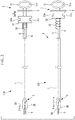
- FIG. 3 is an explanatory view of a relation between a shape of an inserting section and a position of a proximal end portion of a wire in the treatment tool of FIG. 1 , and shows a state where the inserting section linearly extends (an upper illustration), and a state where the inserting section is curved (a middle illustration and a lower illustration).
- FIG. 4A is an explanatory view of a path length of the wire when the inserting section linearly extends.
- FIG. 4B is an explanatory view of a path length of the wire when the inserting section is curved.
- FIG. 5 is a graph showing a relation between a curve angle of the inserting section and the grip force of the end effector in the treatment tool of FIG. 1 (a solid line) and a treatment tool of a comparative example (a broken line).
- FIG. 6 is an overall configuration view of the treatment tool of FIG. 1 (an upper illustration), and a modification of the treatment tool of FIG. 1 (a lower drawing).
- FIG. 7A is an explanatory view of a path length of a wire when an inserting section linearly extends in a treatment tool of the modification of FIG. 6 .
- FIG. 7B is an explanatory view of a path length of the wire when the inserting section is curved in the treatment tool of the modification of FIG. 6 .
- FIG. 8 is an overall configuration view of a treatment tool according to a second embodiment of the present invention, and shows a state where an inserting section linearly extends (an upper illustration) and a state where the inserting section is curved (a lower illustration).
- FIG. 9 is a graph showing a relation between a curve angle of the inserting section and a pulling force by an operating section in the treatment tool of FIG. 8 (a solid line) and a treatment tool of a comparative example (a broken line).
- FIG. 10 is an overall configuration view of a modification of the treatment tool of FIG. 8 , and shows a state where an inserting section linearly extends (an upper illustration) and a state where the inserting section is curved (a lower illustration).
- FIG. 11 is an overall configuration view of a treatment tool according to a third embodiment of the present invention, and shows a state where an inserting section linearly extends (an upper illustration) and a state where the inserting section is curved (a lower illustration).
- FIG. 12 is an overall configuration view of modifications of the treatment tools according to the first to third embodiments.
- FIG. 13 is an overall configuration view of other modifications of the treatment tools according to the first to third embodiments.
- FIG. 14 is an overall configuration view of another modification of the treatment tools according to the first to third embodiments.
- FIG. 15 is an overall configuration view of another modification of the treatment tools according to the first to third embodiments.
- FIG. 16 is an overall configuration view of another modification of the treatment tools according to the first to third embodiments.
- FIG. 17 is an overall configuration view of another modification of the treatment tools according to the first to third embodiments.
- the treatment tool 100 includes a flexible elongated inserting section 1 , an end effector 2 connected to a tip of the inserting section 1 , an operating section (a power input section) 3 that is disposed on a proximal end side of the inserting section 1 , and generates power to drive the end effector 2 by an operation of an operator, and a wire (a power transmission member) 4 that extends through the inserting section 1 to connect the end effector 2 to the operating section 3 , and transmits the power input from the operating section 3 to the end effector 2 .
- the inserting section 1 includes a tubular member having flexibility, for example, a coil sheath.
- the wire 4 is disposed movably in a longitudinal direction.
- a tip portion of the wire 4 is fixed to the end effector 2 , and a proximal end portion of the wire 4 is drawn out from a proximal end of the inserting section 1 , and is connected to an elastic member 33 of the operating section 3 as described later.
- a treatment to increase slidability is performed on the surface of the wire 4 .
- the surface of the wire 4 is coated with a high slidability material (a low friction material), or lubricant is applied to the surface.
- the end effector 2 includes a pair of grip forceps having grip pieces 2 A, 2 B that are openable and closable to each other.
- the end effector 2 is configured to open by a pressing force (power) applied from the wire 4 toward a tip side, and to close by a pulling force (the power) applied from the wire 4 toward the proximal end side. Therefore, a size of a grip force generated by the end effector 2 is controlled by the pulling force from the wire 4 .
- the end effector 2 is not limited to the pair of grip forceps, and another type of end effector (e.g., a knife) that receives power to perform a mechanical operation may be adopted.
- the end effector 2 may be configured so that a joint provided in the end effector 2 is driven by the power from the wire 4 .
- the operating section 3 includes an operating section main body 31 fixed to the inserting section 1 , a slider (an operation member) 32 that is movable in a direction along the longitudinal direction of the inserting section 1 between the inserting section 1 and the operating section main body 31 , and an elastic member 33 disposed between a proximal end portion of the wire 4 and the slider 32 to connect the proximal end portion of the wire 4 to the slider 32 .
- the operating section main body 31 is fixed to an end portion of a columnar connection member 6 extending from the proximal end of the inserting section 1 to the proximal end side (a side opposite to the tip of the inserting section 1 ) along the longitudinal direction of the inserting section 1 .
- a hole 31 a is provided in which a thumb can be inserted
- grooves 32 a , 32 b are provided that receive an index finger and a middle finger, respectively.
- the operator inserts the thumb in the hole 31 a of the operating section main body 31 , and places the index finger and the middle finger in the grooves 32 a and 32 b , respectively, to grip the slider 32 between the index finger and the middle finger.
- the operator moves the index finger and the middle finger in a direction away from the thumb to advance the slider 32 to the tip side, and moves the index finger and the middle finger in a direction close to the thumb, so that the slider 32 can be retracted to the proximal end side (an operating section main body 31 side).
- a movement amount of the slider 32 to the proximal end side is limited by a movement regulating section 5 including a member disposed between the slider 32 and the operating section main body 31 and fixed to the operating section main body 31 .
- the slider 32 can retract back to a movement limit position at which the slider abuts on the movement regulating section 5 .
- the elastic member 33 is, for example, a coil spring, and is disposed on an outer side of the connection member 6 to expand and contract in the longitudinal direction of the inserting section 1 .
- a tip portion of the elastic member 33 is fixed to the proximal end portion of the wire 4 , and a proximal end portion of the elastic member 33 is fixed to the slider 32 .
- FIG. 2 shows a relation between movement of the slider 32 and the grip force generated by the end effector 2 .
- the slider 32 is movable between a closed position to close the end effector 2 (see an upper illustration of FIG. 2 ) and the movement limit position located closer to a proximal end side than the closed position and allowing the end effector 2 to exert a predetermined amount of grip force (see a lower illustration of FIG. 2 ).
- the pulling force is input into the proximal end portion of the wire 4 toward the proximal end side via the elastic member 33 having a natural length.
- the pulling force is transmitted to the end effector 2 through the wire 4 , to close the end effector 2 .
- the grip pieces 2 A, 2 B are only lightly in contact with each other, and a grip force F is hardly generated between the grip piece 2 A and the grip piece 2 B.
- the elastic member 33 When the slider 32 moves from the closed position toward the movement limit position, a position of the proximal end portion of the wire 4 does not change, and the elastic member 33 elongates.
- the elongated elastic member 33 generates an elastic force toward the proximal end side. This elastic force is input as the pulling force into the proximal end portion of the wire 4 , and the grip force is accordingly generated in the end effector 2 .
- the wire 4 is not extended by the pulling force, or extends only negligibly.
- the elastic member 33 when the slider 32 is disposed at the movement limit position, the elastic member 33 elongates up to a maximum amount to maximize the pulling force to be input into the proximal end portion of the wire 4 , and the grip force F of the end effector 2 is maximized.
- X indicates a movement amount (an operation amount) of the slider 32 from the closed position to the movement limit position, when the inserting section 1 has the linear shape.
- each of the proximal end portion of the wire 4 , the elastic member 33 and the slider 32 is displaced as much as ⁇ X toward the tip side, and the movement amount (a maximum operation amount) of the slider 32 from the closed position to the movement limit position therefore increases as much as ⁇ X.
- the slider 32 is disposed at the movement limit position (see a lower illustration of FIG. 3 )
- an elongation amount of the elastic member 33 increases as much as ⁇ X
- the pulling force applied to the proximal end portion of the wire 4 increases as much as k ⁇ X, where k is the spring constant of the elastic member 33 .
- FIG. 4A and FIG. 4B explain a relation between a curve angle ⁇ of the inserting section 1 and a displacement amount ⁇ X of the proximal end portion of the wire 4 .
- a part of the inserting section 1 having a length L of the linear shape as shown in FIG. 4A is circularly curved at an angle ⁇ as shown in FIG. 4B
- the wire 4 on which the pulling force acts closely contacts an inner surface of the inserting section 1 on an inner side in a radial direction.
- a length L′ of the wire 4 in a curved portion of the inserting section 1 is represented by the following equation, where ⁇ b is a diameter of the wire 4 , and t is a thickness of a side wall of the inserting section 1 .
- L′ L +( ⁇ b/ 2+ t ) ⁇
- the displacement amount ⁇ X of the proximal end portion of the wire 4 when the inserting section 1 is curved at the angle ⁇ is represented by ( ⁇ b/2+t) ⁇ .
- the displacement amount ⁇ X of the wire 4 increases linearly in accordance with the curve angle ⁇ of the inserting section 1 .
- a friction coefficient A of the surface of the wire 4 is sufficiently small, and the power transmission efficiency ⁇ can be therefore approximated as in the above equation. That is, the power transmission efficiency ⁇ of the wire 4 linearly decreases in accordance with the curve angle ⁇ of the inserting section 1 .
- a maximum grip force F[N] exerted by the end effector 2 when the inserting section 1 linearly extends and a maximum grip force F′[N] exerted by the end effector 2 when the inserting section 1 is curved are represented by the following equations, respectively, where a indicates a value in which there are taken into account the power transmission efficiency of the wire 4 when the inserting section 1 linearly extends, a power amount transmission efficiency of the end effector 2 , and a deceleration rate (a power amount amplification factor) of the end effector 2 .
- F k ⁇ X ⁇
- F′ k ⁇ ( X+ ⁇ X ) ⁇
- ⁇ b and t indicate designed values of the wire 4 and the inserting section 1 , respectively.
- the friction coefficient ⁇ is experimentally measured.
- the curve angle ⁇ of the inserting section 1 is almost constant depending on a procedure, and therefore determined in accordance with the procedure.
- the operator inserts the inserting section 1 into a body to place the end effector 2 of the tip in a vicinity of the tissue S.
- the operator advances the slider 32 provided in the operating section 3 from the closed position to open the end effector 2 , and holds the tissue S between the pair of pieces of the end effector 2 .
- the operator retracts the slider 32 back to the closed position to close the end effector 2 to lightly grip an affected area therewith.
- the operator retracts the slider 32 back to the movement limit position to generate a predetermined amount of grip force in the end effector 2 , so that the affected area can be tightly gripped with the end effector 2 .
- the inserting section 1 is curved in the body, and the power transmission efficiency ⁇ of the wire 4 accordingly decreases in proportion to the curve angle ⁇ .
- the proximal end portion of the wire 4 is displaced as much as the amount ⁇ X in proportion to the curve angle ⁇ , and the pulling force generated by the elastic member 33 increases as much as k ⁇ X.
- the power to be input into the proximal end portion of the wire 4 is increased as much as an amount based on the displacement amount ⁇ X of the proximal end portion of the wire 4 , so that the loss of power due to the decrease of the power transmission efficiency ⁇ of the wire 4 can be highly accurately compensated.
- FIG. 5 is a graph showing one example of a relation between a total curve angle ⁇ of the inserting section 1 and the grip force F, F′ of the end effector 2 .
- a solid line shows one example of the present embodiment, and a broken line shows a comparative example.
- ⁇ 540 (deg)
- ⁇ b 0.22 (mm)
- t 0.2 (mm)
- ⁇ 4E ⁇ 4 (deg ⁇ 1 ).
- the grip force F′ noticeably decreases as the curve angle ⁇ of the inserting section 1 increases.
- the grip force F′ can be maintained to be almost constant irrespective of the curve angle ⁇ of the inserting section 1 .
- the wire 4 is freely movable in the radial direction within the inserting section 1 , but instead of this, there may be provided a means that defines a position of the wire 4 in the radial direction within the inserting section 1 so that the wire 4 is always located on a central axis of the inserting section 1 irrespective of the shape of the inserting section 1 .
- a means that defines a position of the wire 4 in the radial direction within the inserting section 1 so that the wire 4 is always located on a central axis of the inserting section 1 irrespective of the shape of the inserting section 1 .
- an inner sheath 7 having an outer diameter almost equal to an inner diameter of the inserting section 1 and having an inner diameter almost equal to an outer diameter of the wire 4 may be disposed in the inserting section 1 , and the wire 4 may be disposed in the inner sheath 7 .
- the length L′ of the wire 4 in the curved portion of the inserting section 1 is represented by the following equation, and the displacement amount ⁇ X is represented by ( ⁇ a/2+t) ⁇ .
- ⁇ a is the inner diameter of the inserting section 1 .
- L′ L +( ⁇ a/ 2+ t ) ⁇
- the displacement amount ⁇ X increases, and the movement amount of the slider 32 from the closed position to the movement limit position therefore increases. This facilitates fine adjustment of the operation of the end effector 2 .
- ⁇ b 0.1 to 0.5 [mm] (a case where the inner sheath 7 is provided)
- a position to install the movement regulating section 5 is determined so that the initial movement amount X of the slider 32 is in the following range: 2.4 mm ⁇ X ⁇ 272 mm.
- the grip force F, F′ required for the end effector 2 is in a range of 10 N to 100 N.
- a spring constant k of the elastic member 33 which is required to exert the grip force F, F′ of 10 N is about 0.037 [N/mm]
- a spring constant k of the elastic member 33 which is required to exert the grip force F, F′ of 100 N is about 40 [N/mm]. That is, use of the elastic member 33 having a spring constant of 0.037 [N/mm] or more and 40 [N/mm] or less allows the end effector 2 to exert the grip force F, F′ of a size suitable for practical use.
- the treatment tool 200 includes an inserting section 1 , an end effector 2 , an operating section (a power input section) 30 that is provided on a proximal end side of the inserting section 1 and into which power to drive the end effector 2 is input by an operation of an operator, and a wire 4 .
- the operating section 30 includes an operating section main body 31 , a slider 32 , and an elastic member (a power generating portion) 33 disposed between the operating section main body 31 and the slider 32 .
- a proximal end portion of the wire 4 is fixed to the slider 32 . Therefore, in the present embodiment, a pulling force and a pressing force applied to the slider 32 by the operator are directly input into the proximal end portion of the wire 4 .
- a tip portion of the elastic member 33 is fixed to the slider 32 , and a proximal end portion of the elastic member 33 is fixed to the operating section main body 31 .
- a length of the elastic member 33 is a natural length.
- a pulling force fa of the elastic member 33 By this pulling force fa of the elastic member 33 , a pulling operation of the slider 32 by the operator is assisted.
- the elastic member 33 in the state where the inserting section 1 is curved, the elastic member 33 generates the pulling force as much as an amount k ⁇ X in proportion to a displacement amount ⁇ X of the proximal end portion of the wire 4 , and power to be input into the proximal end portion of the wire 4 increases.
- This has an advantage that by applying a constant amount of pulling force f to the slider 32 by the operator, the end effector 2 is allowed to exert a constant amount of grip force F irrespective of a curve angle ⁇ of the inserting section 1 .
- the wire 4 may be configured to be always located on a central axis of the inserting section 1 irrespective of a shape of the inserting section 1 .
- FIG. 9 is a graph showing one example of a relation between a total curve angle ⁇ of the inserting section 1 and the pulling force f of the slider 32 required to allow the end effector 2 to exert a constant amount (10 N) of grip force.
- a solid line shows one example of the present embodiment, and a broken line shows a comparative example.
- ⁇ 540 (deg)
- ⁇ b 0.22 (mm)
- t 0.2 (mm)
- ⁇ 4E ⁇ 4 (deg ⁇ 1 ).
- a required pulling force f increases as a curve angle ⁇ of the inserting section 1 increases.
- a constant grip force can be exerted by a constant pulling force f irrespective of the curve angle ⁇ of the inserting section 1 .
- an elastic force of the elastic member 33 is utilized as power that assists the operation of the slider 32 by the operator, but instead of this, a magnetic force that acts on an iron core (a power generating portion) 81 fixed to the slider 32 may be utilized as shown in FIG. 10 .
- a solenoid (a power generating portion) 82 in which the iron core 81 is inserted is fixed to an operating section main body 31 , and a controller 83 that controls a current to be supplied to the solenoid 82 is connected to the solenoid 82 .
- the iron core 81 is displaced together with a slider 32 by displacement of a wire 4 , and self-inductance of the solenoid 82 accordingly changes.
- the controller 83 detects a displacement amount ⁇ X of the wire 4 based on a change amount of the self-inductance of the solenoid 82 , and increases the current to be supplied to the solenoid 82 in accordance with the displacement amount ⁇ X, to increase the magnetic force to be applied to the slider 32 via the iron core 81 . Also when the magnetic force is utilized in this way, a pulling operation of the slider 32 by an operator can be assisted.
- the treatment tool 300 includes an inserting section 1 , an end effector 2 , a driving section (a power input section) 9 that is provided on a proximal end side of the inserting section 1 and generates power to drive the end effector 2 , a wire 4 that extends through the inserting section 1 and connects the end effector 2 to the driving section 9 to transmit, to the end effector 2 , the power input from the driving section 9 , a displacement detector 10 that detects a displacement amount of a proximal end portion of the wire 4 , and a controller 11 that controls the driving section 9 .
- the driving section 9 is, for example, a linear actuator, and presses or pulls the proximal end portion of the wire 4 in a longitudinal direction.
- the displacement detector 10 measures, for example, a distance between markers 10 a and 10 b fixed to a proximal end of the inserting section 1 and a middle position of the wire 4 in the longitudinal direction, respectively.
- the displacement detector 10 can detect a displacement amount ⁇ X of the proximal end portion of the wire 4 from the distance between the markers 10 a and 10 b .
- Information of the detected displacement amount ⁇ X of the proximal end portion of the wire 4 is transmitted from the displacement detector 10 to the controller 11 .
- the controller 11 receives an operation signal to the end effector 2 from an unshown operation input device, and drives the driving section 9 based on the operation signal, thereby causing the end effector 2 to perform an operation corresponding to the operation input into the operation input device. At this time, the controller 11 increases a pulling force to be generated in the driving section 9 in accordance with the displacement amount ⁇ X of the proximal end portion of the wire 4 , when receiving the operation signal for grip by the end effector 2 .
- the pulling force to be input into the proximal end portion of the wire 4 from the driving section 9 in accordance with the displacement amount ⁇ X of the proximal end portion of the wire 4 is increased; by the increase of the pulling force, loss of power due to decrease of a power transmission efficiency ⁇ of the wire 4 can be highly accurately compensated.
- This has an advantage that irrespective of a curve angle ⁇ of the inserting section 1 , a constant amount of power is applied from a tip portion of the wire 4 to the end effector 2 , thereby allowing the end effector 2 to exert a constant amount of grip force.
- the end effector 2 is opened and closed by pushing and pulling one wire 4 , but instead of this, as shown in FIG. 12 , a wire 4 A for an opening operation and a wire 4 B for a closing operation may be separately provided.
- FIG. 12 shows an example where two wires 4 A and 4 B are applied to the first embodiment as one example.
- Proximal end portions of the two wires 4 A and 4 B are connected to a common drum (operating member) 34 that is rotatable around an axis in a direction crossing a longitudinal direction of an inserting section 1 and that is rotationally operated by an operator.
- the opening wire 4 A is pulled to a proximal end side by clockwise rotation of the drum 34 to open an end effector 2
- the closing wire 4 B is pulled to the proximal end side by counterclockwise rotation of the drum 34 to close the end effector 2 .
- the closing wire 4 B is provided with an elastic member 33 , and a stopper 35 that abuts on a movement regulating section 5 to limit further pulling of the closing wire 4 B by the drum 34 .
- the opening wire 4 A has slack between a proximal end of the inserting section 1 and the drum 34 in a state where the inserting section 1 linearly extends. Consequently, as shown in a lower illustration of FIG. 12 , displacement of the opening wire 4 A to a tip side is absorbed by deflection in a state where the inserting section 1 is curved.
- a closing wire 4 B may have slack between an elastic member 33 and a drum 34 .
- the end effector 2 may include an energy release section 21 that releases energy such as heat, an ultrasonic wave or a current, and may include an energy supply member 22 , such as an electric wire, that supplies the energy to the energy release section 21 .
- an energy supply member 22 such as an electric wire
- the energy supply member 22 is wired from the end effector 2 through an inserting section 1 to a power source.
- the energy supply member 22 is drawn out between a proximal end of the inserting section 1 and an elastic member 33 so that the energy supply member 22 does not interfere with the elastic member 33 .
- an energy supply member 22 may be passed through a tubular elastic member 33 such as a coil spring, and the energy supply member 22 may be drawn out on a proximal end side of the elastic member 33 .
- the inserting section 1 is flexible, but as shown in FIG. 16 and FIG. 17 , there may be adopted a hard inserting section 12 having a joint 12 a that is bendable around an axis perpendicular to a longitudinal direction.
- FIG. 16 shows an example where the inserting section 12 is applied to the treatment tool 100 of the first embodiment
- FIG. 17 shows an example where the inserting section 12 is applied to the treatment tool 200 of the second embodiment.
- An end effector 2 is connected to an operating section 3 by a plurality of rods 41 coupled to one another via a link 42 , in place of the wire 4 .
- the link 42 is provided in the joint 12 a , and the link 42 is configured to also bend when the joint 12 a bends.
- the rod 41 is displaced on a proximal end side, not on a tip side, by inward displacement of the link 42 in a radial direction. Therefore, in the modifications of FIG. 15 and FIG. 16 , the end effector 2 is configured to close by movement of a slider 32 to the tip side.
- an initial movement amount X of the slider 32 is designed to satisfy Equation (1) described in the first embodiment.
- a spring constant k of the elastic member 33 is designed to satisfy Equation (2) described in the second embodiment.
- a treatment tool includes an elongated inserting section that is curveable or bendable, an end effector connected to a tip of the inserting section, an elongated power transmission member that is disposed through the inserting section from the end effector to a proximal end side of the inserting section and transmits, to the end effector, power to drive the end effector, and a power input section that is disposed on the proximal end side of the inserting section and inputs the power to a proximal end portion of the power transmission member, wherein the power input section increases the power to be input into the proximal end portion of the power transmission member in response to displacement of the proximal end portion of the power transmission member in a longitudinal direction, the displacement accompanying a curve or bend of the inserting section.
- the power input from the power input section into the proximal end portion of the power transmission member is transmitted to the end effector by the power transmission member, thereby allowing the end effector to perform a mechanical operation.
- the power transmission member disposed in the inserting section is also curved or bent. Consequently, the proximal end portion of the power transmission member is displaced in the longitudinal direction, and a power transmission efficiency of the power transmission member decreases.
- the power transmission efficiency of the power transmission member almost linearly decreases, and the displacement of the proximal end portion of the power transmission member almost linearly increases. That is, an almost linear relation is present between the decrease of the power transmission efficiency of the power transmission member and the displacement of the proximal end portion of the power transmission member. Therefore, the input of the power increases in response to the displacement of the proximal end portion of the power transmission member, so that loss of power due to the decrease of the power transmission efficiency can be favorably compensated by the increase of the input of the power. Consequently, a certain amount of power can be transmitted to the end effector irrespective of the curve or bend of the inserting section.
- the power input section may include an operation member that is connected to the proximal end portion of the power transmission member, and is operated in the longitudinal direction by an operator to input, into the proximal end portion of the power transmission member, the power based on an operation amount, and a maximum operation amount of the operation member may be increased by the displacement of the proximal end portion of the power transmission member.
- the power input section may include an elastic member that connects the proximal end portion of the power transmission member to the operation member, and generates an elastic force in a reverse direction to a direction of the displacement of the proximal end portion of the power transmission member by an operation of the operation member, and the treatment tool may include a movement regulating section that regulates the operation amount of the operation member.
- the elastic force generated by elastically deforming the elastic member by the operation of the operation member can be input as the power into the proximal end portion of the power transmission member.
- an elastically deformable amount of the elastic member is increased by the displacement of the proximal end portion of the power transmission member. Therefore, the power that can be input into the proximal end portion of the power transmission member can be increased.
- the operation amount of the operation member is regulated by the movement regulating section, so that a size of the power that can be input into the proximal end portion of the power transmission member via the operation member by the operator can be limited to be less than or equal to a predetermined value.
- the movement regulating section may regulate, in the following range, the operation amount X of the operation member in a state where the inserting section linearly extends: 2.4 mm ⁇ X ⁇ 272 mm.
- the treatment tool may include two power transmission members each of which transmits power to the end effector, the operation member and the elastic member may be connected to a proximal end portion of one of the two power transmission members, and in a state where the inserting section linearly extends, the one power transmission member may have slack between the elastic member and the operation member, or the other power transmission member may have slack.
- two operations e.g., an opening operation and a closing operation
- two operations e.g., an opening operation and a closing operation
- the power input section may include a power generating portion that is connected to the proximal end portion of the power transmission member, and generates power in a reverse direction to a direction of the displacement of the proximal end portion of the power transmission member by the displacement of the proximal end portion of the power transmission member, the displacement accompanying the curve or bend of the inserting section.
- the power in the reverse direction to the direction of the displacement of the proximal end portion of the power transmission member is applied from the power generating portion to the proximal end portion of the power transmission member.
- the power to be input into the proximal end portion of the power transmission member can be increased.
- the power generating portion may include an elastic member that is elastically deformable in the longitudinal direction.
- the elastic member elastically deformed by the displacement of the proximal end portion of the power transmission member generates an elastic force in a reverse direction to the direction of the displacement of the proximal end portion of the power transmission member, and this elastic force is applied to the proximal end portion of the power transmission member.
- the elastic force of the elastic member is proportional to an elastically deformed amount, that is, a displacement amount of the proximal end portion of the power transmission member. Therefore, the power to be input into the proximal end portion of the power transmission member is increased by the elastic force of the elastic member, so that loss of power in the power transmission member can be highly accurately compensated.
- the elastic member may have a spring constant of 0.037 N/mm or more and 40 N/mm or less.
- a size of the power to be generated by the elastic member can be controlled in a range that is suitable for a small-diameter inserting section to be inserted into a body.
- a surface of the power transmission member may be coated with a high slidability material.
- the end effector may include an energy release section that releases energy, and may include an energy supply member that supplies the energy to the energy release section.
- the energy is released from the energy release section to a tissue, so that a treatment of cauterization, incision, coagulation or the like can be performed.
Abstract
Description
L′=L+(Φb/2+t)×θ
β=exp(−λθ)≈1−λ×θ
F=k×X×α
F′=k×(X+ΔX)×β×α
where Φb and t indicate designed values of the
L′=L+(Φa/2+t)×θ
2.4 mm<X<272 mm.
f+fa=f/β
k=(1−β)×f/ΔX (2)
2.4 mm<X<272 mm.
- 100, 200 and 300 treatment tool
- 1 and 12 inserting section
- 12 a joint
- 2 end effector
- 21 energy release section
- 22 energy supply member
- 2A and 2B grip piece
- 3 operating section (a power input section)
- 31 operating section main body
- 32 slider (an operation member)
- 33 elastic member (a power generating portion)
- 4 wire (a power transmission member)
- 41 rod (a power transmission member)
- 42 link
- 5 movement regulating section
- 7 inner sheath
- 81 iron core (a power generating portion)
- 82 solenoid (a power generating portion)
- 9 driving section (a power input section)
- 10 displacement detector
- 11 controller
Claims (15)
Applications Claiming Priority (1)
| Application Number | Priority Date | Filing Date | Title |
|---|---|---|---|
| PCT/JP2017/018631 WO2018211648A1 (en) | 2017-05-18 | 2017-05-18 | Treatment tool |
Related Parent Applications (1)
| Application Number | Title | Priority Date | Filing Date |
|---|---|---|---|
| PCT/JP2017/018631 Continuation WO2018211648A1 (en) | 2017-05-18 | 2017-05-18 | Treatment tool |
Publications (2)
| Publication Number | Publication Date |
|---|---|
| US20200078033A1 US20200078033A1 (en) | 2020-03-12 |
| US11382645B2 true US11382645B2 (en) | 2022-07-12 |
Family
ID=64273601
Family Applications (1)
| Application Number | Title | Priority Date | Filing Date |
|---|---|---|---|
| US16/681,988 Active 2038-01-11 US11382645B2 (en) | 2017-05-18 | 2019-11-13 | Treatment tool |
Country Status (2)
| Country | Link |
|---|---|
| US (1) | US11382645B2 (en) |
| WO (1) | WO2018211648A1 (en) |
Citations (8)
| Publication number | Priority date | Publication date | Assignee | Title |
|---|---|---|---|---|
| US20050090837A1 (en) | 2003-03-25 | 2005-04-28 | Sixto Robert Jr. | Endoscopic surgical instrument having a force limiting actuator |
| US20060217743A1 (en) | 2005-03-28 | 2006-09-28 | Messerly Jeffrey D | Medical instrument with a mechanical coupling |
| US20060258954A1 (en) * | 2005-05-13 | 2006-11-16 | Tyler Timberlake | Biopsy forceps assemblies |
| WO2010109932A1 (en) | 2009-03-24 | 2010-09-30 | オリンパスメディカルシステムズ株式会社 | Robot system for endoscope treatment |
| US20100268254A1 (en) * | 2007-11-12 | 2010-10-21 | Joe Alan Golden | Clamp System and Method of Using the Same |
| US20110288579A1 (en) | 2010-05-18 | 2011-11-24 | Olympus Corporation | Manipulator |
| WO2012118011A1 (en) | 2011-03-03 | 2012-09-07 | オリンパスメディカルシステムズ株式会社 | Treatment tool for endoscope |
| JP2013215507A (en) | 2012-04-12 | 2013-10-24 | Terumo Corp | Medical manipulator |
-
2017
- 2017-05-18 WO PCT/JP2017/018631 patent/WO2018211648A1/en active Application Filing
-
2019
- 2019-11-13 US US16/681,988 patent/US11382645B2/en active Active
Patent Citations (19)
| Publication number | Priority date | Publication date | Assignee | Title |
|---|---|---|---|---|
| US20050090837A1 (en) | 2003-03-25 | 2005-04-28 | Sixto Robert Jr. | Endoscopic surgical instrument having a force limiting actuator |
| JP4954501B2 (en) | 2004-06-14 | 2012-06-20 | エシコン・エンド−サージェリィ・インコーポレイテッド | Endoscopic surgical instrument with actuator to limit force |
| CA2509915A1 (en) | 2004-06-14 | 2005-12-14 | Ethicon Endo-Surgery, Inc. | Endoscopic surgical instrument having a force limiting actuator |
| EP1607055A1 (en) | 2004-06-14 | 2005-12-21 | Ethicon Endo-Surgery, Inc. | Endoscopic surgical instrument having a force limiting actuator |
| JP2006000634A (en) | 2004-06-14 | 2006-01-05 | Ethicon Endo Surgery Inc | Endoscopic surgical instrument having force limiting actuator |
| US20060217743A1 (en) | 2005-03-28 | 2006-09-28 | Messerly Jeffrey D | Medical instrument with a mechanical coupling |
| EP1707129A1 (en) | 2005-03-28 | 2006-10-04 | Ethicon Endo-Surgery, Inc. | Mechanical coupling element between actuating rod and actuator of a medical instrument |
| JP2006271975A (en) | 2005-03-28 | 2006-10-12 | Ethicon Endo Surgery Inc | Medical apparatus equipped with mechanical connection section |
| US20060258954A1 (en) * | 2005-05-13 | 2006-11-16 | Tyler Timberlake | Biopsy forceps assemblies |
| US20100268254A1 (en) * | 2007-11-12 | 2010-10-21 | Joe Alan Golden | Clamp System and Method of Using the Same |
| WO2010109932A1 (en) | 2009-03-24 | 2010-09-30 | オリンパスメディカルシステムズ株式会社 | Robot system for endoscope treatment |
| US20110106141A1 (en) | 2009-03-24 | 2011-05-05 | Toshio Nakamura | Robot system for endoscopic treatment |
| EP2305144A1 (en) | 2009-03-24 | 2011-04-06 | Olympus Medical Systems Corp. | Robot system for endoscope treatment |
| US20110288579A1 (en) | 2010-05-18 | 2011-11-24 | Olympus Corporation | Manipulator |
| JP2011239922A (en) | 2010-05-18 | 2011-12-01 | Olympus Corp | Manipulator |
| WO2012118011A1 (en) | 2011-03-03 | 2012-09-07 | オリンパスメディカルシステムズ株式会社 | Treatment tool for endoscope |
| EP2554129A1 (en) | 2011-03-03 | 2013-02-06 | Olympus Medical Systems Corp. | Treatment tool for endoscope |
| US20130046338A1 (en) | 2011-03-03 | 2013-02-21 | Olympus Medical Systems Corp. | Treatment instrument for endoscope |
| JP2013215507A (en) | 2012-04-12 | 2013-10-24 | Terumo Corp | Medical manipulator |
Non-Patent Citations (1)
| Title |
|---|
| International Search Report dated Aug. 8, 2017 issued in PCT/JP2017/018631. |
Also Published As
| Publication number | Publication date |
|---|---|
| US20200078033A1 (en) | 2020-03-12 |
| WO2018211648A1 (en) | 2018-11-22 |
Similar Documents
| Publication | Publication Date | Title |
|---|---|---|
| JP7428761B2 (en) | Stapler beam structure | |
| US20180050456A1 (en) | Grasping mechanism and grasping device | |
| US9510824B2 (en) | Low profile medical device and related methods of use | |
| JP5542288B2 (en) | Passive preload and capstan drive for surgical instruments | |
| EP2997912B1 (en) | Endoscope treatment tool | |
| US20100063527A1 (en) | Tissue pad | |
| US20100063528A1 (en) | Ultrasonic shears actuating mechanism | |
| EP1974675B1 (en) | Endoscopic treatment tool | |
| US8758266B2 (en) | Treatment instrument for endoscope | |
| US11147643B2 (en) | Manipulator | |
| US20200039093A1 (en) | Force transmitting mechanism and instrument | |
| CN107249831B (en) | Mechanical arm | |
| US10582976B2 (en) | Manipulator system and manipulator control method | |
| US11666349B2 (en) | Endovascular apparatus | |
| US11382645B2 (en) | Treatment tool | |
| US20170209164A1 (en) | Medical treatment tool | |
| US11457917B2 (en) | Treatment instrument | |
| JP6180694B2 (en) | Suture device | |
| CN111200983B (en) | Medical device | |
| EP3439727B1 (en) | Steering tool with controlled distal flexibility | |
| EP3520717B1 (en) | Clip removal device | |
| US20210137545A1 (en) | Motive-power transmitting mechanism and treatment tool | |
| WO2018220844A1 (en) | Power transmission mechanism and treatment tool | |
| WO2022029833A1 (en) | Medical manipulator system | |
| CN114947997A (en) | Surgical tool with reduced actuation force |
Legal Events
| Date | Code | Title | Description |
|---|---|---|---|
| AS | Assignment |
Owner name: OLYMPUS CORPORATION, JAPAN Free format text: ASSIGNMENT OF ASSIGNORS INTEREST;ASSIGNOR:NAKAMURA, TAKASHI;REEL/FRAME:050990/0954 Effective date: 20191105 |
|
| FEPP | Fee payment procedure |
Free format text: ENTITY STATUS SET TO UNDISCOUNTED (ORIGINAL EVENT CODE: BIG.); ENTITY STATUS OF PATENT OWNER: LARGE ENTITY |
|
| STPP | Information on status: patent application and granting procedure in general |
Free format text: DOCKETED NEW CASE - READY FOR EXAMINATION |
|
| STPP | Information on status: patent application and granting procedure in general |
Free format text: NON FINAL ACTION MAILED |
|
| STPP | Information on status: patent application and granting procedure in general |
Free format text: RESPONSE TO NON-FINAL OFFICE ACTION ENTERED AND FORWARDED TO EXAMINER |
|
| STPP | Information on status: patent application and granting procedure in general |
Free format text: FINAL REJECTION MAILED |
|
| STPP | Information on status: patent application and granting procedure in general |
Free format text: RESPONSE AFTER FINAL ACTION FORWARDED TO EXAMINER |
|
| STPP | Information on status: patent application and granting procedure in general |
Free format text: NOTICE OF ALLOWANCE MAILED -- APPLICATION RECEIVED IN OFFICE OF PUBLICATIONS |
|
| STPP | Information on status: patent application and granting procedure in general |
Free format text: PUBLICATIONS -- ISSUE FEE PAYMENT VERIFIED |
|
| STCF | Information on status: patent grant |
Free format text: PATENTED CASE |