US11376753B2 - Disposable utility knife with safety lock - Google Patents
Disposable utility knife with safety lock Download PDFInfo
- Publication number
- US11376753B2 US11376753B2 US16/515,693 US201916515693A US11376753B2 US 11376753 B2 US11376753 B2 US 11376753B2 US 201916515693 A US201916515693 A US 201916515693A US 11376753 B2 US11376753 B2 US 11376753B2
- Authority
- US
- United States
- Prior art keywords
- handle
- tab
- blade
- knife
- shuttle
- Prior art date
- Legal status (The legal status is an assumption and is not a legal conclusion. Google has not performed a legal analysis and makes no representation as to the accuracy of the status listed.)
- Active
Links
Images


Classifications
-
- B—PERFORMING OPERATIONS; TRANSPORTING
- B26—HAND CUTTING TOOLS; CUTTING; SEVERING
- B26B—HAND-HELD CUTTING TOOLS NOT OTHERWISE PROVIDED FOR
- B26B5/00—Hand knives with one or more detachable blades
- B26B5/001—Hand knives with one or more detachable blades with blades being slid out of handle immediately prior to use
-
- B—PERFORMING OPERATIONS; TRANSPORTING
- B26—HAND CUTTING TOOLS; CUTTING; SEVERING
- B26B—HAND-HELD CUTTING TOOLS NOT OTHERWISE PROVIDED FOR
- B26B29/00—Guards or sheaths or guides for hand cutting tools; Arrangements for guiding hand cutting tools
- B26B29/02—Guards or sheaths for knives
-
- B—PERFORMING OPERATIONS; TRANSPORTING
- B26—HAND CUTTING TOOLS; CUTTING; SEVERING
- B26B—HAND-HELD CUTTING TOOLS NOT OTHERWISE PROVIDED FOR
- B26B1/00—Hand knives with adjustable blade; Pocket knives
- B26B1/08—Hand knives with adjustable blade; Pocket knives with sliding blade
Definitions
- the present invention relates to knives of the type commonly used to open and cutup corrugated boxes, cut sheetrock and other materials, and more particularly, to such knives that are disposable (i.e., of the type which provides no access to replace blades).
- the blade used in most utility knives has been standardized. It is generally made from sheet steel and is trapezoidal in planar shape.
- the long edge of the trapezoid-shaped blade is sharpened and defines the cutting edge of the blade.
- the short edge, opposite the cutting edge, (or top edge) of the blade includes two symmetrical U-shaped notches, directed towards the cutting edge.
- the two sides are symmetrically angled to connect the short edge with the long cutting edge, as is well known by those of ordinary skill in the art.
- a conventional utility knife handle is usually made up of two hollow halves that may be selectively locked to each other to form a study handle and define a combined hollow cavity in which the blade holder and blade may reside and operate (as well as provide storage for additional blades).
- the combined handle assembly further includes a slot through which a portion of the blade holder may pass, in the form of a tab (finger purchase).
- the tab provides operational access to the user so that the user may selectively slide the blade holder, and therefore the blade as desired within a restricted range of displacement, while holding the handle.
- the blade holder (and blade) may be selectively displaced between a fully retracted position and an extended position. The blade in the fully retracted position is safely positioned within the housing. In contrast, the blade in the extended position exposes a portion of its cutting edge beyond one end of the handle so that useful cutting work may be performed by the user.
- the blades of many such conventional utility knives can be replaced when they become dull, either by separating the two handle-halves or by feeding a new blade directly into the blade holder from the front of the knife.
- providing a feature of allowing replacement of a dull blade is generally beneficial
- several disposable utility knives are commercially available today.
- Some of these disposable utility knives include automatically activated safety covers or shields which move to cover and protect the otherwise exposed sharpened edge when the blade is not being used to cut, yet remains on “standby” with the blade protruding from the handle.
- a problem with conventional disposable type utility knives is that they are still relatively expensive, considering that they only provide a single blade and when that blade dulls, the knife must be disposed. These knives also typically only offer a short cutting edge, between 1 ⁇ 4′′ and 3 ⁇ 8′′. There have been complaints that the short cutting edge is not sufficient to fully cut thick corrugated shipping boxes and the shorter blade often dulls more quickly since a concentrated section of the blade is relied upon to perform all the cutting.
- a portable utility knife comprising: a hollow elongated handle sized and shaped to be easily gripped by a user's hand, the handle including an upper surface and opposing first and second ends, the hollow handle defining a cavity therein; an elongated slot disposed along the upper surface, the slot providing access through the handle to the cavity; a first opening located at the first end and a second opening located at the second end, the first and second openings extending through the handle to the cavity; a blade shuttle positioned within the cavity and selectively slidable between the first end and the second end; a razor blade secured to the shuttle, the razor blade having a cutting edge, the cutting edge defining a first cutting edge section and a second cutting edge section so that when the shuttle is positioned within the cavity and adjacent the first end, the first cutting edge section of the razor blade extends through the first opening of the handle to expose the first cutting edge section to provide useful cutting work, and when the shuttle is positioned adjacent the second end,
- a tab attached to the blade shuttle, the tab extending through the elongated slot so that a portion of the tab is accessible to a user, the tab may be used to slide the shuttle within the cavity between the first and second ends; and a movable locking component attached to the handle, the locking component being selectively moveable between a first position, wherein the tab is prevented from sliding within the elongated slot, and a second position, wherein the tab is permitted to slid within the elongated slot.
- the knife comprising: an elongated handle having opposing first and second ends; a blade assembly slidably attached to the handle, the blade assembly being selectively slidable between the first and second ends, the blade assembly including a cutting edge that is exposed for useful work by the user when the blade assembly is located adjacent one of the first and second ends; and
- an obstructive component moveably attached to the handle, the obstructive component being moveable between an obstructive position, wherein sliding passage of the blade assembly between the first and second ends of the handle is prevented and a non obstructive position, wherein sliding passage of the blade assembly between the first and second ends is permitted.
- the blade assembly further comprises a tab and wherein the hollow handle comprises an elongated slot through which the tab is positioned and along which the tab may slide.
- a safety knife for use by a user, the knife comprising: an elongated handle having opposing first and second ends; a blade assembly slidably attached to the handle, the blade assembly being selectively slidable between the first and second ends, the blade assembly including a cutting edge that is exposed for useful work by the user when the blade assembly is located adjacent one of the first and second ends; an access tab attached to the blade assembly, the access tab being accessible to the user; and a U-shaped locking component pivotally attached to the handle between a blocking position, wherein the tab is physically blocked from sliding between the first and second ends, and a non-blocking position, wherein the tab is permitted to slide between the first and second ends; an obstructive component moveably attached to the handle, the obstructive component being moveable between an obstructive position, wherein sliding passage of the blade assembly between the first and second ends of the handle is prevented and a non obstructive position, wherein sliding passage of the
- a low cost disposable utility knife includes a hollow handle having an elongated slot and an opening at each end.
- a blade shuttle holds a trapezoidal razor blade and is slidably mounted on tracks integrally formed within the hollow handle and slidable between each end of the handle. When the shuttle is located at either end, a cutting edge of the razor extends beyond the opening of the adjacent handle end and is accessible for useful cutting work by a user.
- the shuttle includes a tab that is positioned within the elongated slot and includes a portion that is accessible to the user. The user may use the accessible tab to slide the shutter and the blade within the handle between the two ends, as desired.
- a U-Shaped flip lock is pivotally attached to the handle between a down position, wherein the tab is physically blocked from sliding along the elongated slot, and an up position, wherein the tab is permitted to slide along the elongated slot, passing under the U-shaped flip lock.
- the elongated slot may further include at least one locking notch into which a portion of the tab may selectively engage.
- the tab may be spring-biased to automatically engage the at least one locking notch when the tab resides adjacent thereto.
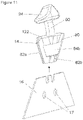
- FIG. 1 is a side elevation view of a utility knife, according to the present invention, including a handle, a blade, a blade shuttle having an integral finger tab and a flip lock shown in a first down and locked position, the blade being shown in an extended position at a first end of the handle labeled “TWO”.
- FIG. 2 is a perspective view of the knife of FIG. 1 , according to the present invention.
- FIG. 3 is a perspective view of the knife of FIG. 1 , showing the blade shuttle repositioned to a midpoint of the handle, and showing the flip lock being moved to a vertical unlocked position so that finger tab may pass from a first end of the handle, labeled “TWO,” to an opposite end of the handle, labeled “ONE,” according to the present invention.
- FIG. 4 is a perspective view of the knife of FIG. 3 , showing the blade shuttle still at the midpoint of the handle, but showing the flip lock being moved to a second down and locked position, thereby preventing the blade shuttle from accidentally returning to the first end of the handle, labeled “TWO,” allowing the finger tab, and the blade shuttle located within the handle, to only advance to the second end of the handle, labeled “ONE,” indicated by the arrow, according to the present invention.
- FIG. 5 is a perspective view of the knife of FIG. 4 , showing the flip lock still in the second down and locked position, and showing the finger tab, and therefore the blade shuttle located at the second end of the handle, labeled “ONE,” with the blade in an extended position, according to the present invention.
- FIG. 6 is a perspective view of one handle half of the knife of FIG. 1 , showing details of the blade shuttle, the finger tab, and a blade, according to the present invention.
- FIG. 7 is a plan side view of one handle half of the knife of FIG. 1 , showing representative blade shuttles and blades and flip locks to illustrate the range of movement of the blade shuttle and blade, from one end of the handle to the other, and the range of movement of the flip lock, from a first locked position, to a unlocked vertical position, and back to a second locked position, according to the present invention.
- FIG. 8 is a sectional view of the knife of FIG. 4 , taken along the line 8 - 8 of FIG. 4 , showing details of the blade shuttle, guide rails, blade support rail, the flip lock, and the finger tab, according to the present invention
- FIG. 9 is an exploded perspective view of the knife of FIG. 1 , showing assembly details, according to the present invention.
- FIG. 10 is an assembly view of the knife of FIG. 1 , showing the handle halves in a separated orientation to reveal internal structural details, according to the invention
- FIG. 11 is an assembly view of the shuttle and blade, according to the invention.
- FIG. 12 is an enlarged partial side view of the shuttle, blade and handle halve, showing details of a blade-anti-rotation structure, according to the invention.
- FIG. 13 is a side view of the shuttle and blade, according to another embodiment of the present invention.
- FIG. 14 a is a plan view of a safety label having an exemplary shape, according to another embodiment of the invention.
- FIG. 14 b is a perspective view of the knife of the present invention showing the safety label of FIG. 14 a secured thereto, and providing the knife with security, according to this embodiment of the invention.
- ranges mentioned herein include all ranges located within the prescribed range. As such, all ranges mentioned herein include all sub-ranges included in the mentioned ranges. For instance, a range from 100-200 also includes ranges from 110-150, 170-190, and 153-162. Further, all limits mentioned herein include all other limits included in the mentioned limits. For instance, a limit of up to 7 also includes a limit of up to 5, up to 3, and up to 4.5.
- a disposable utility knife 10 having a handle 12 , made up of two halves 12 a and 12 b , a blade shuttle 14 , supporting a metal razor blade 16 , and a flip lock 18 .
- the basic structure of knife 10 is that although it is meant to be disposable, it provides the user two separate blades, so this knife will last twice as long as similar knives that offer only a single blade.
- the basic structure of knife 10 is similar to the one disclosed in U.S. Pat. No. 8,701,293 of Scott Sullivan, entitled “Utility Knife,” in that both designs include a handle and a slidable blade that can be selectively displaced from one end to the other to effectively provide two separate cutting edges.
- the entire content of U.S. Pat. No. 8,701,293 is hereby incorporated by this reference.
- each handle half 12 a , 12 b is preferably made from an appropriate strong lightweight thermoplastic, such as ABS, and is made so that when the two halves are secured together, a cavity 20 is formed therebetween.
- an appropriate strong lightweight thermoplastic such as ABS
- Handle half 12 a includes an arcuate upper surface 22 , defining an upper slot 23 , a first end 24 having a first end recess 26 , a second opposing end 28 having a second end recess 30 .
- Recesses 26 , 30 are sized and shaped to accommodate blade 16 , as described in greater detail below.
- Handle half 12 a further includes a pair of integrally formed arcuate shuttle guide rails 32 a and 32 b , and an integrally formed arcuate blade guide rail 34 .
- Blade guide rail 34 , shuttle guide rails 32 a , 32 b and upper surface 22 preferably have common radius of curvature and are therefore effectively parallel to each other.
- Handle half 12 a further includes a lower grip-bulge 36 , which provides a gripping point for a user holding the assembled knife 10 .
- Upper surface 22 are preferably at least three locking notches 38 a , 38 b , and 38 c , which help lock blade shuttle 14 at prescribed positions about handle 12 , as described below.
- Handle half 12 a further includes upper protrusions 40 a , 40 b located adjacent first end 24 and second end 28 , respectively, and lower central protrusion 42 , which are sized and shaped to snugly receive similarly shaped recesses located on the opposing handle half 12 b , as described below.
- Handle half 12 a further includes a post 44 which projects outward from the handle half and is centrally located, near upper surface 22 , as shown in FIG. 8 .
- Handle half 12 b has many similar features to that of handle half 12 a , including an arcuate upper surface 50 , defining an upper slot 51 , a first end 52 having a first end recess 54 , a second opposing end 56 having a second end recess 58 . Recesses 54 , 58 are sized and shaped to accommodate blade 16 , as described in greater detail below. Handle half 12 b further includes a pair of integrally formed arcuate shuttle guide rails 60 a and 60 b . Handle half 12 b does not require a blade guide rail, as does handle 12 a . Shuttle guide rails 60 a , 60 b and upper surface 50 preferably have common radius of curvature and are therefore effectively parallel to each other.
- Handle half 12 b further includes a lower grip-bulge 66 , which provides a gripping point for a user holding the assembled knife 10 .
- upper surface 50 does not require any locking notches.
- Handle half 12 b further includes upper recesses 70 a , 70 b , adjacent first end 52 and second end 56 , respectively, and lower central recess 72 , which are sized and shaped to snugly receive similarly shaped protrusions 40 a , 40 b and 42 located on the opposing handle half 12 a , introduced above.
- Handle half 12 b further includes a post 74 which projects outward from the handle half and is centrally located, near upper surface 50 , as shown in FIG. 8 .
- blade shuttle 14 is meant to securely hold razor blade 16 and move the blade within handle 12 .
- Blade 16 can be glued to shuttle 14 , but is preferably molded to shuttle 14 during the injection-molding of shuttle 14 using an insert molding process wherein blade 16 is inserted into the mold of shuttle 14 before plastic is injected into the mold. In the injection molding process, the molten plastic forms shuttle 14 around the inserted blade 16 , to create a shuttle and blade assembly, which is shown in FIGS. 6, 8, 9 and 12 .
- blade 16 preferably includes bores 17 which aid in securing blade 16 to shuttle 14 during the molding process, as is well known by those of ordinary skill in the art.
- shuttle 14 includes a flat trapezoidal-shaped body 80 which extends on both sides of blade 16 , defining a left side 82 a , and a right side 82 b .
- Body 80 includes a left side guide channel 84 a and a right side guide channel 84 b .
- left side guide channel 84 a is sized and shaped to snugly and slidably engage guide rails 32 a , 32 b of handle half 12 a , as shown in FIG. 8 .
- right side guide channel 84 b of body 80 is sized and shaped to snugly and slidably engage guide rails 60 a , 60 b of handle half 12 b .
- a stem 90 extends from a top surface 122 of shuttle body 80 .
- stem 90 is formed with a slight curve.
- a finger tab 94 is formed at the upper end of stem 90 .
- slots 23 and 51 of the two handle halves 12 a , 12 b ) combine to form a slot 95 that is sized to fit curved stem 90 .
- the type of plastic used to make shuttle 14 is preferably strong and resilient, and if possible naturally lubricious.
- the plastic used to make shuttle 14 can be different from the plastic used to make handle halves 12 a , 12 b.
- flip lock 18 is a U-shaped structure with two parallel side bars 96 connected at one end of each to a crossbar 98 .
- a bearing boss 100 with a central bore 102 is formed at the open end of each side bar 96 .
- Bore 102 of each bearing boss 100 is sized to snugly fit onto posts 44 , 74 , so that flip lock 18 becomes pivotally attached to the outside of each handle half 12 a , 12 b with crossbar 98 positioned across upper surfaces 22 , 50 of handle halves 12 a , 12 b .
- Flip lock 18 is pivotal between a first locked position (closer to the handle end labeled “ONE”), shown in FIG. 1 , a vertical unlocked position, shown in FIG.
- Each handle half 12 a , 12 b may further include a first lock channel 104 and a second lock channel 106 , each of which is sized and shaped to receive a portion of crossbar 98 , as shown in FIGS. 2, 4 , and 5 .
- Flip lock 18 is preferably made from a strong resilient plastic, such as ABS or PVC.
- shuttle 14 is adapted to snugly slide within handle cavity 20 along shuttle guide rails 32 a and 32 b of handle half 12 a and shuttle guide rails 60 a and 60 b of handle 12 b ,
- a shuffle gap 110 is created between shuttle guide rails 32 a , 32 b of handle half 12 a and shuttle guide rails 60 a and 60 b of handle 12 b , within which shuffle 14 resides and slides.
- Shuttle guide mils 32 a,b , 60 a,b guide shuttle 14 along the arcuate path defined by the shape of the guide rails as the shuttle moves between first end 24 and second end 28 of handle 12 . As shown in FIGS.
- handle 12 a includes blade guide rail 34 which is meant to support blade 16 and prevent shuttle 14 and blade 16 from rotating.
- blade guide rail 34 When tab 94 is pushed laterally against the natural spring bias of stem 90 to release the stem from one of the locking notches 38 a - c , the lateral push force may cause shuttle 14 to rotate within handle 12 a small degree, thereby forcing blade 16 in the opposite direction, against blade guide rail 34 .
- Blade guide rail 34 prevents blade 16 from rotating, Since tab 94 will only be pushed in one lateral direction, a blade guide rail 34 is only required on handle half 12 a , as shown in the figures.
- shuttle 14 with blade 16 secured therein is positioned within handle half 12 a so that curved tab 94 is bent toward locking notches 38 a - c , and so that left side guide channel 84 a of shuttle body 80 is mounted to shuttle guide rails 32 a and 32 b .
- Handle half 12 b is then positioned against handle half 12 a so that lower central protrusion 42 of handle half 12 a enters lower central recess 72 of handle half 12 b , and upper protrusions 40 a , 40 b of handle half 12 a enter upper recesses 70 a , 70 b of handle half 12 b , respectfully.
- the two handle halves 12 a and 12 b are then securely bonded to each other, preferably using an ultrasonic welding process so that the two plastic handle halves literally weld to each other at all points of contact.
- shuttle 14 and blade 16 can be moved between first end 24 and second end 28 .
- the final step is to position flip lock 18 over the top of handle 12 so that crossbar 98 resides across upper surfaces 22 , 50 and so that central bores 102 of each bearing boss 100 resides over each post 44 , 74 of handle 12 .
- a user holds knife 10 , according to the present invention, in one hand.
- FIG. 1 As a starting point in explaining the operation of knife 10 , reference is made to FIG. 1 , wherein shuttle 14 (not visible in FIG. 1 because it is located within cavity 20 of handle 12 ) and blade 16 are located at second end 28 of handle 12 so that blade 16 extends past handle 12 exposing a first cutting edge portion 110 for useful work.
- stem 90 is engaged with locking notch 38 c by the stem's spring-bias. Therefore, when stem 90 of shuttle 14 is engaged in any locking notch 38 a , 38 b , or 38 c , shuttle 14 and blade 16 are locked in that position.
- stem 90 when the user if done cutting for the moment, he or she may disengage stem 90 from locking notch 38 c by using his or her thumb to move tab 94 against the spring-bias of stem 90 until the stem is disengaged from locking notch 38 c , at which point, the user may use his or her thumb to slide tab 94 within slot 95 to a center position, wherein stem 90 automatically engages with locking notch 38 b , as shown in FIG. 2 , due to the spring-bias resiliency of stem 90 .
- knife 10 includes flip lock 18 .
- Tab 94 cannot be accidentally moved to the opposite first end 24 of handle 12 because tab 94 is blocked from advancing past flip lock 18 , since crossbar 98 of the flip lock is located between the centrally located locking notch 38 b and locking notch 38 a , and also crosses over slot 95 .
- Flip lock 18 effectively retains shuttle 14 and blade 16 safety on one expected side of handle 12 .
- the user may release shuttle 14 from the central locked position of FIG. 2 and again advance, the shuttle and blade 16 forward towards second end 28 of handle 12 until stem 90 again engages with locking notch 38 c and blade 16 again protrudes from handle 12 , as shown in FIG. 1 .
- first cutting edge portion 110 of blade 16 will dull.
- the user may relocate shuttle 14 to the opposite first end 24 of handle 12 to allow usage of a second cutting edge portion 112 of blade 16 .
- the user again moves shuttle 14 and blade 16 back to the central locked position, as shown in FIG. 2 .
- flip lock 18 may be pivoted from first locked position (closer to the handle end labeled “ONE”), shown in FIG. 1 , to a vertical unlocked position, as shown in FIG. 3 and indicated by arrow 19 , and then finally to a second locked position (located closer to the handle end labeled “TWO”), as shown in FIG. 4 .
- crossbar 98 In moving flip lock 18 from the first locked position to the second locked position, crossbar 98 will have moved to the other side of tab 94 .
- This new position now allows the user to advance tab 94 towards the opposite first end 24 , indicated by arrow 114 (towards the handle end labeled “ONE”).
- shuttle 14 is moved all the way to first end 24 of handle 12 , as shown in FIG. 5 , to locked notch 38 a , blade 16 again protrudes from handle 12 , but now revealing second cutting edge portion 112 of blade 16 , which is sharp. The user may now enjoy more cutting time using the newly revealed sharp cutting edge, as shown in FIG. 5 .
- the use of flip lock 18 provides an intuitive and readily understandable means to prevent accidental injury to the user of knife 10 .
- the user In using flip lock 18 , the user must be aware as he or she flips crossbar 98 over tab 94 and therefore will be aware of the new direction of movement of shuttle 14 and blade 16 .
- Knife 10 is easy to understand, easy to use, and safe, and it provides twice the cutting life as conventional disposable utility knives.
- stem 90 can be formed straight and can easily, slide along slot 95 without locking.
- Flip lock 18 would still prevent shuttle 14 and blade 16 from traversing to the opposite end of handle 12 . In use, with this arrangement, the user will have to retain a thumb (or finger) on tab 94 to continually force blade 16 in an extended condition during a cutting operation.
- locking techniques may be used in place of the laterally spring-biased stem 90 and locking notches 38 a - 38 c .
- Other locking mechanisms can be used as well.
- shuttle 14 of the present invention when shuttle 14 of the present invention is positioned at either end 24 , 28 of handle 12 and a user pulls tab 94 back using his or her thumb to retract blade 16 into handle 12 , shuttle 14 may torque a bit owing to the moment arm provided by the tab and stem length. This torque may cause shuttle 14 to rotate a bit and therefore bind between guide channels 84 a , 84 b and respective guide rails 32 , 60 . The result is that the shuttle will not move smoothly along guide rails 32 , 60 until shuttle moves away from the handle end. To overcome this potential issue, the present invention provides specific handle structure to support shuttle 14 at the end locations 24 , 28 so that it does not rotate when tab 94 is pulled by the user's thumb. The support structure is shown in FIG.
- a support wall 120 is positioned to snugly contact a portion of upper surface 122 of shuttle 14 when shuttle 14 is advanced fully to either end 24 , 28 of handle 12 .
- shuttle cannot rotate because the rotational force generated by the user's pulling force is cancelled by an equal and opposite force generated by upper surface 122 of shuttle 14 contacting support wall 120 .
- the end result is that shuttle 14 remains aligned with guide rails 32 , 60 and shuttle moves smoothly along the entire length of the guide rails.
- a blade 130 is formed to include two different shaped cutting edges, a first cutting edge 132 which is shown straight, and an opposing second cutting edge 134 is shown curved.
- knife 10 can offer two different types of cutting, instead of just providing the user with another sharp cutting edge.
- one side of blade 130 can be formed with a shorter cutting edge than the other so that when one side of the blade is used, it will cut less deep into the material. This may be useful for cutting boxes. If a deeper cut is required, the user may simple slide the shuttle and blade to the opposite side of the knife handle, as described above.
- the present utility knife 10 is inexpensive to manufacture and is meant to provide a user a low cost disposable utility knife.
- the knife packaging can include features that provide safety to the customer, while allowing the customer a controlled amount of operational access to the knife, without removing the knife from any packaging.
- FIGS. 9, 14 a , and 14 b a safety label 130 is shown, according to another aspect of the present invention.
- FIG. 14 a a plan view of a label 130 is shown having an exemplary shape to help explain its inventive features, according to the present invention.
- Label 130 is sized and shaped to be secured to handle 12 of knife 10 , as shown in the FIG. 14 b .
- label 130 is meant to be centered on top surface 50 of knife 10 and folded down against each outside surface of handle halve 12 a , 12 b , symmetrically.
- label 130 is, in this example, generally circular in shape, includes a central opening 132 and defines an upper printable surface 134 and an opposing adhesive surface (not shown).
- Label 130 is preferably applied to handle 12 , once assembled at a point of manufacture. Label 130 bonds to handle 12 by the adhesive, which is selected depending on the material chosen for handle 12 the material chosen for the label 130 and whether or not the label is to be removed by peeling (see below).
- An important feature of label 130 is that it is made from a strong tear-resistant material, such as a fiber-reinforced material.
- Tyvek® made by DuPontTM of Wilmington, Del.
- Tyvek® is a unique nonwoven material made of 100% high density polyethylene fibers randomly laid and compressed to form a tough, tear-resistant and printable substrate. Tyvek® can be provided with an application-based adhesive on one surface and be printed with product marketing and use information on printable surface 134 .
- label 130 is securely affixed to handle 12 of knife 10 so that tab 94 and flip lock 18 is positioned within central opening 132 .
- Central opening 132 is preferably sized and shaped to allow a predetermined and controlled amount of sliding displacement of tab 94 within slot 95 before tab 94 contacts a portion of label 130 and is blocked from further movement by sections 136 of label 130 which cover slot 95 , as shown in FIG. 14 b .
- flip lock 18 may be pivoted between its full range of movement by a customer.
- Central opening 132 of label 130 is sized and shaped to only allow some sliding movement of tab 94 , and is small enough to stop the sliding movement of tab 94 before blade 16 (not shown in FIGS.
- label 130 provides a customer limited “testing” movement of tab 94 and flip lock 18 , when deciding to purchase knife 10 , while preventing the customer from moving tab 94 sufficiently to extend blade 16 beyond either end of handle 12 .
- Blade 16 and therefore cutting edges 110 , 112 remain safely within handle 12 while knife 10 is being “tested” by a customer in a store.
- Safety label 130 allows a customer to safely handle knife 10 in a store, learn its features without exposing any sharp edges, and while requiring a minimal amount of low-cost packaging (a label).
- Knife 10 with the use of safety label 130 is therefore suitable for so-called “dump bin” marketing wherein low-cost minimally packaged products in a store may be provided to a customer in a large bin from which one product may be selectively removed by the customer for purchase.
- the safety label 130 shown in FIGS. 14 a , 14 b is generally circular in perimeter shape with a generally circular central cutout
- the shape and size of label 130 may vary according to the specific handle shape and operational details of knife 10 .
- the specific shape and size of knife 10 and all the components, and label 130 is meant to be exemplary to help explain the present invention.
- other shaped knife components including handle halves 12 a , 12 b , blade 16 , shuttle 14 , flip-lock 18 , tab 94 , and label 130 may be used without departing from the spirit and scope of the present invention.
- An additional aspect of the present invention allows for a process of using a utility knife comprising the steps of providing a portable utility knife comprising: a hollow elongated handle sized and shaped to be easily gripped by a user's, hand, said handle including an upper surface and opposing first and second ends, said hollow handle defining a cavity therein; an elongated slot disposed along said upper surface, said slot providing access through said handle to said cavity; a first opening located at said first end and a second opening located at said second end, said first and second openings extending through said handle to said cavity; a blade shuttle positioned within said cavity and selectively slidable between said first end and said second end; a razor blade secured to said shuttle, said razor blade having a cutting, edge, said cutting edge defining a first cutting edge section and a second cutting edge section so that when said shuttle is positioned within said cavity and adjacent said first end, said first cutting edge section of said razor blade extends through said first opening of said handle to expose said first cutting edge section to provide useful cutting work, and
Abstract
Description
Claims (19)
Priority Applications (1)
| Application Number | Priority Date | Filing Date | Title |
|---|---|---|---|
| US16/515,693 US11376753B2 (en) | 2018-07-18 | 2019-07-18 | Disposable utility knife with safety lock |
Applications Claiming Priority (2)
| Application Number | Priority Date | Filing Date | Title |
|---|---|---|---|
| US201862699741P | 2018-07-18 | 2018-07-18 | |
| US16/515,693 US11376753B2 (en) | 2018-07-18 | 2019-07-18 | Disposable utility knife with safety lock |
Publications (2)
| Publication Number | Publication Date |
|---|---|
| US20200156269A1 US20200156269A1 (en) | 2020-05-21 |
| US11376753B2 true US11376753B2 (en) | 2022-07-05 |
Family
ID=70728696
Family Applications (1)
| Application Number | Title | Priority Date | Filing Date |
|---|---|---|---|
| US16/515,693 Active US11376753B2 (en) | 2018-07-18 | 2019-07-18 | Disposable utility knife with safety lock |
Country Status (1)
| Country | Link |
|---|---|
| US (1) | US11376753B2 (en) |
Families Citing this family (2)
| Publication number | Priority date | Publication date | Assignee | Title |
|---|---|---|---|---|
| WO2018053796A1 (en) * | 2016-09-23 | 2018-03-29 | 杭州巨星工具有限公司 | Utility knife provided with double blades |
| US11945126B1 (en) * | 2023-09-19 | 2024-04-02 | Microtech Knives, Inc. | Pocket knife |
Citations (53)
| Publication number | Priority date | Publication date | Assignee | Title |
|---|---|---|---|---|
| US373580A (en) * | 1887-11-22 | Pocket-knife | ||
| US2569080A (en) | 1949-02-24 | 1951-09-25 | Trimble Ernest | Knife using a detachable razor blade |
| US2862296A (en) * | 1957-07-25 | 1958-12-02 | Anderson Tool & Mfg Company | Knife |
| US2870537A (en) * | 1958-03-14 | 1959-01-27 | Ortner Samuel | Pocket safety knife |
| US3448518A (en) * | 1967-07-27 | 1969-06-10 | Harry Sklar | Knife |
| US3478427A (en) * | 1967-09-26 | 1969-11-18 | Camson Mfg Co | Handtool for cutting sheet material |
| US3660896A (en) | 1970-04-10 | 1972-05-09 | Russell Harrington Cutlery Inc | Utility knife |
| USD310474S (en) * | 1988-01-19 | 1990-09-11 | Daniel Bartsch | Retractable double blade knife |
| US5093994A (en) * | 1990-09-20 | 1992-03-10 | Christine Bringman | Double ended-retractable knife |
| US5230152A (en) * | 1991-12-04 | 1993-07-27 | Kennedy Michael J | Dual blade utility knife |
| US5277888A (en) | 1989-06-19 | 1994-01-11 | Merck Patent Gesellschaft Beschrankter Haftung | Dispersions of spherical inorganic particles |
| USD355345S (en) * | 1993-11-29 | 1995-02-14 | Drust Norbert F | Retractable blade utility knife |
| US5490331A (en) * | 1995-05-26 | 1996-02-13 | Gold; Peter | Utility knife for cutting and scraping |
| US5545175A (en) | 1993-06-18 | 1996-08-13 | Leonard Bloom | Disposable quarded finger scalpel for inserting a line in a patent and lock off therefor |
| US5569282A (en) | 1992-12-04 | 1996-10-29 | Werner; Richard S. | Retractable surgical knife |
| US5779724A (en) | 1992-12-04 | 1998-07-14 | Werner; Richard S. | Retractable surgical knife |
| US5806189A (en) * | 1997-04-15 | 1998-09-15 | Bailey; Arthur | Utility knife |
| US5906049A (en) * | 1998-02-09 | 1999-05-25 | Butts; Robert | Double-ended utility knife with two covers |
| US5909930A (en) * | 1997-08-05 | 1999-06-08 | Millers Falls Tool Company | Retractable blade utility knife having quick change feature |
| US5960544A (en) * | 1996-04-03 | 1999-10-05 | Beyers; Greg L. | Double-ended dual mechanism retractable blade utility knife |
| US6006433A (en) * | 1998-02-19 | 1999-12-28 | Baltazar; Mercedes | Multi-purpose knife |
| US6148522A (en) * | 1996-10-18 | 2000-11-21 | Dobandi; Frank | Dual-blade utility knife |
| USD435418S (en) * | 1999-08-13 | 2000-12-26 | Gregory L. Beyers | Double-ended dual blade utility knife |
| US6349473B1 (en) | 2000-08-11 | 2002-02-26 | Alterra Holdings Corporation | Utility knife |
| US20030079347A1 (en) | 2001-10-25 | 2003-05-01 | Adco Industries, Inc. | Box cutter with deflectable safety shield |
| US6637112B2 (en) | 2001-10-25 | 2003-10-28 | Dallco Marketing, Inc. | Box cutter with deflectable safety shield |
| US20040139614A1 (en) | 2003-01-17 | 2004-07-22 | Tebo Glenn J. | Utility knife |
| US20050144787A1 (en) | 2003-12-29 | 2005-07-07 | Joseph Macri | Multi-blade utility knife handle |
| US6957491B2 (en) | 2001-10-31 | 2005-10-25 | The Stanley Works | Combination utility and sporting knife |
| US7101382B2 (en) | 2002-11-12 | 2006-09-05 | Samuel George | Retractable scalpel |
| US7185435B1 (en) | 2005-11-09 | 2007-03-06 | Awi Acquisition Company | Utility knife with dual blades |
| US7340836B2 (en) * | 2003-07-29 | 2008-03-11 | Accurate Concepts, Inc. | Hand tool for measuring and cutting |
| USD580241S1 (en) * | 2006-11-21 | 2008-11-11 | Juan Carlos Fraga | Double edge straight blade and hook |
| US20090094840A1 (en) | 2007-10-14 | 2009-04-16 | Glen Kanemoto | Safety Cutter Apparatus |
| US7533467B2 (en) | 2001-07-23 | 2009-05-19 | Repetto Llc | Utility knife blade |
| US20090178283A1 (en) | 2008-01-14 | 2009-07-16 | Yuewei Wu | Carpenter knife with locking means |
| US20090223062A1 (en) | 2008-03-07 | 2009-09-10 | Daniel Tucker | Side loading pocket knife |
| US20090235533A1 (en) | 2008-03-24 | 2009-09-24 | Yin Han Huang | Utility knife with a fixed blade and a self-retracting blade |
| US7603779B2 (en) * | 2005-09-12 | 2009-10-20 | The Stanley Works | Double ended knife |
| US20100223793A1 (en) * | 2009-03-04 | 2010-09-09 | The Stanley Works | Utility knife |
| US20100281696A1 (en) | 2009-05-04 | 2010-11-11 | Wen Hao | Self loading utility knife |
| US8006388B1 (en) * | 2008-01-04 | 2011-08-30 | Dejesus Thomas | Combination retractable knife and saw utility tool |
| CN102189558A (en) * | 2011-04-28 | 2011-09-21 | 杭州巨星科技股份有限公司 | Bidirectional utility knife |
| US8220161B2 (en) * | 2010-07-28 | 2012-07-17 | Chih-Wei Chang | Multi-function cutter |
| US8689450B2 (en) * | 2011-04-29 | 2014-04-08 | Acme United Corporation | Knife having a reversible carriage |
| US8701293B2 (en) * | 2009-10-14 | 2014-04-22 | Scott L. Sullivan | Utility knife |
| US20140373363A1 (en) * | 2013-03-15 | 2014-12-25 | Harry S. Billado, JR. | Utility Knife |
| US9656397B2 (en) * | 2011-09-01 | 2017-05-23 | Fiskars Finland Oy Ab | Retractable knife or saw with security hook |
| US9925674B2 (en) * | 2012-12-19 | 2018-03-27 | Slice, Inc. | Pocket cutter |
| US20190210233A1 (en) * | 2016-09-23 | 2019-07-11 | Hangzhou Great Star Industrial Co., Ltd. | Utility knife with dual blades |
| US20200122346A1 (en) * | 2018-10-17 | 2020-04-23 | Erosion Runner, L.P. | Self-retracting knife with replaceable blade |
| US10834984B2 (en) * | 2015-10-08 | 2020-11-17 | Dpg Usa Inc. | Dual retractable seam ripper |
| US20220072721A1 (en) * | 2020-09-04 | 2022-03-10 | Able Treasure Enterprise Limited | Finger-push safety knife |
-
2019
- 2019-07-18 US US16/515,693 patent/US11376753B2/en active Active
Patent Citations (54)
| Publication number | Priority date | Publication date | Assignee | Title |
|---|---|---|---|---|
| US373580A (en) * | 1887-11-22 | Pocket-knife | ||
| US2569080A (en) | 1949-02-24 | 1951-09-25 | Trimble Ernest | Knife using a detachable razor blade |
| US2862296A (en) * | 1957-07-25 | 1958-12-02 | Anderson Tool & Mfg Company | Knife |
| US2870537A (en) * | 1958-03-14 | 1959-01-27 | Ortner Samuel | Pocket safety knife |
| US3448518A (en) * | 1967-07-27 | 1969-06-10 | Harry Sklar | Knife |
| US3478427A (en) * | 1967-09-26 | 1969-11-18 | Camson Mfg Co | Handtool for cutting sheet material |
| US3660896A (en) | 1970-04-10 | 1972-05-09 | Russell Harrington Cutlery Inc | Utility knife |
| USD310474S (en) * | 1988-01-19 | 1990-09-11 | Daniel Bartsch | Retractable double blade knife |
| US5277888A (en) | 1989-06-19 | 1994-01-11 | Merck Patent Gesellschaft Beschrankter Haftung | Dispersions of spherical inorganic particles |
| US5093994A (en) * | 1990-09-20 | 1992-03-10 | Christine Bringman | Double ended-retractable knife |
| US5230152A (en) * | 1991-12-04 | 1993-07-27 | Kennedy Michael J | Dual blade utility knife |
| US5569282A (en) | 1992-12-04 | 1996-10-29 | Werner; Richard S. | Retractable surgical knife |
| US5779724A (en) | 1992-12-04 | 1998-07-14 | Werner; Richard S. | Retractable surgical knife |
| US5545175A (en) | 1993-06-18 | 1996-08-13 | Leonard Bloom | Disposable quarded finger scalpel for inserting a line in a patent and lock off therefor |
| USD355345S (en) * | 1993-11-29 | 1995-02-14 | Drust Norbert F | Retractable blade utility knife |
| US5490331A (en) * | 1995-05-26 | 1996-02-13 | Gold; Peter | Utility knife for cutting and scraping |
| US5960544A (en) * | 1996-04-03 | 1999-10-05 | Beyers; Greg L. | Double-ended dual mechanism retractable blade utility knife |
| US6148522A (en) * | 1996-10-18 | 2000-11-21 | Dobandi; Frank | Dual-blade utility knife |
| US5806189A (en) * | 1997-04-15 | 1998-09-15 | Bailey; Arthur | Utility knife |
| US5909930A (en) * | 1997-08-05 | 1999-06-08 | Millers Falls Tool Company | Retractable blade utility knife having quick change feature |
| US5906049A (en) * | 1998-02-09 | 1999-05-25 | Butts; Robert | Double-ended utility knife with two covers |
| US6006433A (en) * | 1998-02-19 | 1999-12-28 | Baltazar; Mercedes | Multi-purpose knife |
| USD435418S (en) * | 1999-08-13 | 2000-12-26 | Gregory L. Beyers | Double-ended dual blade utility knife |
| US6349473B1 (en) | 2000-08-11 | 2002-02-26 | Alterra Holdings Corporation | Utility knife |
| US7533467B2 (en) | 2001-07-23 | 2009-05-19 | Repetto Llc | Utility knife blade |
| US20030079347A1 (en) | 2001-10-25 | 2003-05-01 | Adco Industries, Inc. | Box cutter with deflectable safety shield |
| US6637112B2 (en) | 2001-10-25 | 2003-10-28 | Dallco Marketing, Inc. | Box cutter with deflectable safety shield |
| US6957491B2 (en) | 2001-10-31 | 2005-10-25 | The Stanley Works | Combination utility and sporting knife |
| US7101382B2 (en) | 2002-11-12 | 2006-09-05 | Samuel George | Retractable scalpel |
| US20040139614A1 (en) | 2003-01-17 | 2004-07-22 | Tebo Glenn J. | Utility knife |
| US6848185B2 (en) | 2003-01-17 | 2005-02-01 | Glenn J. Tebo | Utility knife |
| US7340836B2 (en) * | 2003-07-29 | 2008-03-11 | Accurate Concepts, Inc. | Hand tool for measuring and cutting |
| US20050144787A1 (en) | 2003-12-29 | 2005-07-07 | Joseph Macri | Multi-blade utility knife handle |
| US7603779B2 (en) * | 2005-09-12 | 2009-10-20 | The Stanley Works | Double ended knife |
| US7185435B1 (en) | 2005-11-09 | 2007-03-06 | Awi Acquisition Company | Utility knife with dual blades |
| USD580241S1 (en) * | 2006-11-21 | 2008-11-11 | Juan Carlos Fraga | Double edge straight blade and hook |
| US20090094840A1 (en) | 2007-10-14 | 2009-04-16 | Glen Kanemoto | Safety Cutter Apparatus |
| US8006388B1 (en) * | 2008-01-04 | 2011-08-30 | Dejesus Thomas | Combination retractable knife and saw utility tool |
| US20090178283A1 (en) | 2008-01-14 | 2009-07-16 | Yuewei Wu | Carpenter knife with locking means |
| US20090223062A1 (en) | 2008-03-07 | 2009-09-10 | Daniel Tucker | Side loading pocket knife |
| US20090235533A1 (en) | 2008-03-24 | 2009-09-24 | Yin Han Huang | Utility knife with a fixed blade and a self-retracting blade |
| US20100223793A1 (en) * | 2009-03-04 | 2010-09-09 | The Stanley Works | Utility knife |
| US20100281696A1 (en) | 2009-05-04 | 2010-11-11 | Wen Hao | Self loading utility knife |
| US8701293B2 (en) * | 2009-10-14 | 2014-04-22 | Scott L. Sullivan | Utility knife |
| US8220161B2 (en) * | 2010-07-28 | 2012-07-17 | Chih-Wei Chang | Multi-function cutter |
| CN102189558A (en) * | 2011-04-28 | 2011-09-21 | 杭州巨星科技股份有限公司 | Bidirectional utility knife |
| US8689450B2 (en) * | 2011-04-29 | 2014-04-08 | Acme United Corporation | Knife having a reversible carriage |
| US9656397B2 (en) * | 2011-09-01 | 2017-05-23 | Fiskars Finland Oy Ab | Retractable knife or saw with security hook |
| US9925674B2 (en) * | 2012-12-19 | 2018-03-27 | Slice, Inc. | Pocket cutter |
| US20140373363A1 (en) * | 2013-03-15 | 2014-12-25 | Harry S. Billado, JR. | Utility Knife |
| US10834984B2 (en) * | 2015-10-08 | 2020-11-17 | Dpg Usa Inc. | Dual retractable seam ripper |
| US20190210233A1 (en) * | 2016-09-23 | 2019-07-11 | Hangzhou Great Star Industrial Co., Ltd. | Utility knife with dual blades |
| US20200122346A1 (en) * | 2018-10-17 | 2020-04-23 | Erosion Runner, L.P. | Self-retracting knife with replaceable blade |
| US20220072721A1 (en) * | 2020-09-04 | 2022-03-10 | Able Treasure Enterprise Limited | Finger-push safety knife |
Also Published As
| Publication number | Publication date |
|---|---|
| US20200156269A1 (en) | 2020-05-21 |
Similar Documents
| Publication | Publication Date | Title |
|---|---|---|
| US8938883B2 (en) | Cutting implements | |
| US11358292B2 (en) | Ambidextrous utility knife | |
| EP2393641B1 (en) | Hand saw | |
| US7024772B1 (en) | Case knife with multiple position blade guards | |
| US11577412B2 (en) | Utility knife | |
| US11376753B2 (en) | Disposable utility knife with safety lock | |
| US20040139614A1 (en) | Utility knife | |
| US20050278955A1 (en) | Knife having removable blade | |
| US8065803B2 (en) | Cutting tool | |
| US6874188B2 (en) | Multi-tasking utility tool | |
| US8701293B2 (en) | Utility knife | |
| US8099868B1 (en) | Disposable blade cartridge utility knife | |
| US9205568B2 (en) | Ambidextrous utility knife | |
| US8950077B2 (en) | Utility knife apparatus with blades having multiple cutting portions | |
| US20020029480A1 (en) | Blade replacing device for a knife | |
| US3439419A (en) | Knife with slidable blade sheathed and selectively clampable in handle | |
| CA2293332C (en) | Folding razor | |
| US20230118410A1 (en) | Everyday retractable utility cutter | |
| US20050262701A1 (en) | Utility knife having safe locking device | |
| CA1240138A (en) | Open razor | |
| US7954245B2 (en) | Hair thinning scissors | |
| US20240033954A1 (en) | Utility knife with tape breaking structure | |
| US10093027B2 (en) | Safety cutter | |
| US11613031B2 (en) | Utility knife | |
| CA3005069A1 (en) | Utility knife |
Legal Events
| Date | Code | Title | Description |
|---|---|---|---|
| FEPP | Fee payment procedure |
Free format text: ENTITY STATUS SET TO UNDISCOUNTED (ORIGINAL EVENT CODE: BIG.); ENTITY STATUS OF PATENT OWNER: SMALL ENTITY |
|
| FEPP | Fee payment procedure |
Free format text: ENTITY STATUS SET TO SMALL (ORIGINAL EVENT CODE: SMAL); ENTITY STATUS OF PATENT OWNER: SMALL ENTITY |
|
| STPP | Information on status: patent application and granting procedure in general |
Free format text: NON FINAL ACTION MAILED |
|
| STPP | Information on status: patent application and granting procedure in general |
Free format text: NON FINAL ACTION MAILED |
|
| STPP | Information on status: patent application and granting procedure in general |
Free format text: RESPONSE TO NON-FINAL OFFICE ACTION ENTERED AND FORWARDED TO EXAMINER |
|
| STPP | Information on status: patent application and granting procedure in general |
Free format text: FINAL REJECTION MAILED |
|
| STPP | Information on status: patent application and granting procedure in general |
Free format text: ADVISORY ACTION MAILED |
|
| STPP | Information on status: patent application and granting procedure in general |
Free format text: DOCKETED NEW CASE - READY FOR EXAMINATION |
|
| STPP | Information on status: patent application and granting procedure in general |
Free format text: NON FINAL ACTION MAILED |
|
| STPP | Information on status: patent application and granting procedure in general |
Free format text: RESPONSE TO NON-FINAL OFFICE ACTION ENTERED AND FORWARDED TO EXAMINER |
|
| STPP | Information on status: patent application and granting procedure in general |
Free format text: NOTICE OF ALLOWANCE MAILED -- APPLICATION RECEIVED IN OFFICE OF PUBLICATIONS |
|
| STPP | Information on status: patent application and granting procedure in general |
Free format text: PUBLICATIONS -- ISSUE FEE PAYMENT VERIFIED |
|
| STCF | Information on status: patent grant |
Free format text: PATENTED CASE |