US11376139B2 - Pump system - Google Patents
Pump system Download PDFInfo
- Publication number
- US11376139B2 US11376139B2 US16/686,854 US201916686854A US11376139B2 US 11376139 B2 US11376139 B2 US 11376139B2 US 201916686854 A US201916686854 A US 201916686854A US 11376139 B2 US11376139 B2 US 11376139B2
- Authority
- US
- United States
- Prior art keywords
- membrane
- pump mechanism
- prosthetic
- pump
- socket
- Prior art date
- Legal status (The legal status is an assumption and is not a legal conclusion. Google has not performed a legal analysis and makes no representation as to the accuracy of the status listed.)
- Active, expires
Links
Images


Classifications
-
- A—HUMAN NECESSITIES
- A61—MEDICAL OR VETERINARY SCIENCE; HYGIENE
- A61F—FILTERS IMPLANTABLE INTO BLOOD VESSELS; PROSTHESES; DEVICES PROVIDING PATENCY TO, OR PREVENTING COLLAPSING OF, TUBULAR STRUCTURES OF THE BODY, e.g. STENTS; ORTHOPAEDIC, NURSING OR CONTRACEPTIVE DEVICES; FOMENTATION; TREATMENT OR PROTECTION OF EYES OR EARS; BANDAGES, DRESSINGS OR ABSORBENT PADS; FIRST-AID KITS
- A61F2/00—Filters implantable into blood vessels; Prostheses, i.e. artificial substitutes or replacements for parts of the body; Appliances for connecting them with the body; Devices providing patency to, or preventing collapsing of, tubular structures of the body, e.g. stents
- A61F2/50—Prostheses not implantable in the body
- A61F2/68—Operating or control means
-
- A—HUMAN NECESSITIES
- A61—MEDICAL OR VETERINARY SCIENCE; HYGIENE
- A61F—FILTERS IMPLANTABLE INTO BLOOD VESSELS; PROSTHESES; DEVICES PROVIDING PATENCY TO, OR PREVENTING COLLAPSING OF, TUBULAR STRUCTURES OF THE BODY, e.g. STENTS; ORTHOPAEDIC, NURSING OR CONTRACEPTIVE DEVICES; FOMENTATION; TREATMENT OR PROTECTION OF EYES OR EARS; BANDAGES, DRESSINGS OR ABSORBENT PADS; FIRST-AID KITS
- A61F2/00—Filters implantable into blood vessels; Prostheses, i.e. artificial substitutes or replacements for parts of the body; Appliances for connecting them with the body; Devices providing patency to, or preventing collapsing of, tubular structures of the body, e.g. stents
- A61F2/50—Prostheses not implantable in the body
- A61F2/60—Artificial legs or feet or parts thereof
- A61F2/64—Knee joints
-
- A—HUMAN NECESSITIES
- A61—MEDICAL OR VETERINARY SCIENCE; HYGIENE
- A61F—FILTERS IMPLANTABLE INTO BLOOD VESSELS; PROSTHESES; DEVICES PROVIDING PATENCY TO, OR PREVENTING COLLAPSING OF, TUBULAR STRUCTURES OF THE BODY, e.g. STENTS; ORTHOPAEDIC, NURSING OR CONTRACEPTIVE DEVICES; FOMENTATION; TREATMENT OR PROTECTION OF EYES OR EARS; BANDAGES, DRESSINGS OR ABSORBENT PADS; FIRST-AID KITS
- A61F2/00—Filters implantable into blood vessels; Prostheses, i.e. artificial substitutes or replacements for parts of the body; Appliances for connecting them with the body; Devices providing patency to, or preventing collapsing of, tubular structures of the body, e.g. stents
- A61F2/50—Prostheses not implantable in the body
- A61F2/68—Operating or control means
- A61F2/74—Operating or control means fluid, i.e. hydraulic or pneumatic
- A61F2/742—Low pressure systems, e.g. vacuum pump
-
- A—HUMAN NECESSITIES
- A61—MEDICAL OR VETERINARY SCIENCE; HYGIENE
- A61F—FILTERS IMPLANTABLE INTO BLOOD VESSELS; PROSTHESES; DEVICES PROVIDING PATENCY TO, OR PREVENTING COLLAPSING OF, TUBULAR STRUCTURES OF THE BODY, e.g. STENTS; ORTHOPAEDIC, NURSING OR CONTRACEPTIVE DEVICES; FOMENTATION; TREATMENT OR PROTECTION OF EYES OR EARS; BANDAGES, DRESSINGS OR ABSORBENT PADS; FIRST-AID KITS
- A61F2/00—Filters implantable into blood vessels; Prostheses, i.e. artificial substitutes or replacements for parts of the body; Appliances for connecting them with the body; Devices providing patency to, or preventing collapsing of, tubular structures of the body, e.g. stents
- A61F2/50—Prostheses not implantable in the body
- A61F2/78—Means for protecting prostheses or for attaching them to the body, e.g. bandages, harnesses, straps, or stockings for the limb stump
- A61F2/80—Sockets, e.g. of suction type
-
- F—MECHANICAL ENGINEERING; LIGHTING; HEATING; WEAPONS; BLASTING
- F04—POSITIVE - DISPLACEMENT MACHINES FOR LIQUIDS; PUMPS FOR LIQUIDS OR ELASTIC FLUIDS
- F04B—POSITIVE-DISPLACEMENT MACHINES FOR LIQUIDS; PUMPS
- F04B45/00—Pumps or pumping installations having flexible working members and specially adapted for elastic fluids
- F04B45/04—Pumps or pumping installations having flexible working members and specially adapted for elastic fluids having plate-like flexible members, e.g. diaphragms
-
- A—HUMAN NECESSITIES
- A61—MEDICAL OR VETERINARY SCIENCE; HYGIENE
- A61F—FILTERS IMPLANTABLE INTO BLOOD VESSELS; PROSTHESES; DEVICES PROVIDING PATENCY TO, OR PREVENTING COLLAPSING OF, TUBULAR STRUCTURES OF THE BODY, e.g. STENTS; ORTHOPAEDIC, NURSING OR CONTRACEPTIVE DEVICES; FOMENTATION; TREATMENT OR PROTECTION OF EYES OR EARS; BANDAGES, DRESSINGS OR ABSORBENT PADS; FIRST-AID KITS
- A61F2/00—Filters implantable into blood vessels; Prostheses, i.e. artificial substitutes or replacements for parts of the body; Appliances for connecting them with the body; Devices providing patency to, or preventing collapsing of, tubular structures of the body, e.g. stents
- A61F2/50—Prostheses not implantable in the body
- A61F2/60—Artificial legs or feet or parts thereof
- A61F2002/608—Upper legs
-
- A—HUMAN NECESSITIES
- A61—MEDICAL OR VETERINARY SCIENCE; HYGIENE
- A61F—FILTERS IMPLANTABLE INTO BLOOD VESSELS; PROSTHESES; DEVICES PROVIDING PATENCY TO, OR PREVENTING COLLAPSING OF, TUBULAR STRUCTURES OF THE BODY, e.g. STENTS; ORTHOPAEDIC, NURSING OR CONTRACEPTIVE DEVICES; FOMENTATION; TREATMENT OR PROTECTION OF EYES OR EARS; BANDAGES, DRESSINGS OR ABSORBENT PADS; FIRST-AID KITS
- A61F2/00—Filters implantable into blood vessels; Prostheses, i.e. artificial substitutes or replacements for parts of the body; Appliances for connecting them with the body; Devices providing patency to, or preventing collapsing of, tubular structures of the body, e.g. stents
- A61F2/50—Prostheses not implantable in the body
- A61F2/60—Artificial legs or feet or parts thereof
- A61F2/66—Feet; Ankle joints
- A61F2002/6614—Feet
-
- A—HUMAN NECESSITIES
- A61—MEDICAL OR VETERINARY SCIENCE; HYGIENE
- A61F—FILTERS IMPLANTABLE INTO BLOOD VESSELS; PROSTHESES; DEVICES PROVIDING PATENCY TO, OR PREVENTING COLLAPSING OF, TUBULAR STRUCTURES OF THE BODY, e.g. STENTS; ORTHOPAEDIC, NURSING OR CONTRACEPTIVE DEVICES; FOMENTATION; TREATMENT OR PROTECTION OF EYES OR EARS; BANDAGES, DRESSINGS OR ABSORBENT PADS; FIRST-AID KITS
- A61F2/00—Filters implantable into blood vessels; Prostheses, i.e. artificial substitutes or replacements for parts of the body; Appliances for connecting them with the body; Devices providing patency to, or preventing collapsing of, tubular structures of the body, e.g. stents
- A61F2/50—Prostheses not implantable in the body
- A61F2/78—Means for protecting prostheses or for attaching them to the body, e.g. bandages, harnesses, straps, or stockings for the limb stump
- A61F2/80—Sockets, e.g. of suction type
- A61F2002/802—Suction sockets, i.e. utilizing differential air pressure to retain the prosthesis on the stump
Definitions
- the disclosure relates to the field of prosthetic devices, and more particularly to a prosthetic device, system and pump mechanism for increasing vacuum in a vacuum assisted suspension system.
- prosthetic devices An ongoing challenge in the development of prosthetic devices is the attachment of the prosthetic device to the residual limb of a user.
- the lack of a secure attachment can adversely affect the user's ability to walk.
- an improper fit can cause sores, swelling and pain for the user.
- Mechanical pumps are often in-line systems that utilize the movement of the user to generate the negative pressure vacuum in the socket.
- the force generated by contacting the ground during a user's walking motion can be used to generate a vacuum in the socket space to hold the prosthesis to the user's limb.
- known pumps rely on complete compression of the pump to expel air from the pump before the pump can be decompressed to generate the vacuum. Because the impact and displacement of the pump is not consistent and varies between users, the vacuum and thus attachment between the residual limb and the socket can be unpredictable and/or inadequate, causing the user discomfort, grief and even injury. Many of such pumps are also bulky and significantly contribute to the weight of the prosthetic limb, imposing a significant weight burden on the user when walking.
- Embodiments of the prosthetic system provide vacuum assisted suspension by generating negative pressure inside a prosthetic socket worn over a residual limb, and reducing sliding movement between the liner and the socket.
- the prosthetic system of the present disclosure advantageously can produce a vacuum effect in a prosthetic socket utilizing a pivoting, swinging, or rotating mechanism at a joint rather than relying primarily on a force or pressure applied to the prosthetic system by the user.
- the prosthetic system includes first and second parts rotatable relative to one another about a joint.
- the first and second parts form at least part of a weight bearing connection between a prosthetic foot and a socket.
- a pump system includes a pump mechanism operatively connected to the first and second parts.
- Relative rotation between the first and second parts about the joint moves the pump mechanism between an original configuration in which the volume of a fluid chamber defined by the pump mechanism is zero or near-zero, and an expanded configuration in which the volume of the fluid chamber is increased.
- a support member of the pump system flexes or bends, which, in turn, causes a movable member of the pump system to pivot or rotate about the joint and toward the second part.
- the movable member rotates about the joint toward the second part, the movable member rotates away from the support member, which, in turn, moves the pump mechanism toward the expanded configuration, pulling fluid into the pump mechanism.
- stored energy in the support member forces the first and second parts to rotate away from one another. This moves the movable member and the pump mechanism back toward the original configuration, expelling fluid out of the pump mechanism.
- the pump system can thus generate a vacuum in a socket using a pivoting or rotating movement between the first and second parts. Further, it can do so without undesirably affecting the functionality of a prosthetic knee or foot associated with the prosthetic system or significantly increasing the bulk of the system.
- the pump system can be located at or near the socket such that there is no need to move fluid drawn into the pump mechanism from the socket all the way down the prosthetic foot. This advantageously reduces the time required to produce an elevated vacuum in the socket. Further, it eliminates or reduces the need of a long tube extending between the prosthetic foot and the socket, reducing the likelihood of leaks and volume to generate vacuum.
- the pump mechanism can be incorporated into a prosthetic knee.
- the first part can comprise a rotatable part of the prosthetic knee.
- FIG. 1A shows a side view of a prosthetic system according to an embodiment.
- FIG. 1B shows another side view of the prosthetic system in FIG. 1A .
- FIG. 2 shows a side view of a prosthetic system according to another embodiment.
- FIG. 3 shows a side view of a prosthetic system according to another embodiment.
- FIG. 4 shows a side view of a prosthetic system according to another embodiment.
- FIG. 5 shows a side view of a prosthetic system according to another embodiment.
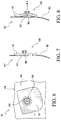
- FIG. 6 shows a top view of a prosthetic system according to another embodiment.
- FIG. 7 shows a side view of the prosthetic system in FIG. 6 .
- FIG. 8 shows another side view of the prosthetic system in FIG. 6 .
- FIG. 9 shows a side view of a prosthetic system including the pump system in FIG. 6 according to an embodiment.
- FIG. 10 shows a perspective view of a prosthetic system including the pump system in FIG. 6 according to another embodiment.
- FIG. 11 shows a perspective view of a pump system according to another embodiment.
- FIG. 12 shows a side view of a prosthetic system including the pump system in FIG. 11 according to an embodiment.
- FIG. 13 shows another side view of the prosthetic system in FIG. 12 .
- FIG. 14 shows a prosthetic system according to another embodiment.
- FIG. 15 shows a cross section view of the prosthetic system in FIG. 14
- a vacuum pump system having a fluid connection with a socket assists in creating a vacuum between a residual limb and the socket by pumping fluid out of the socket.
- the fluid can be pumped out of the socket manually or in swing and/or stance.
- pivotal movement about a joint between a socket and a pylon of the prosthetic system can cause a pump mechanism of the present disclosure to increase the volume of a fluid chamber in the pump mechanism.
- the increase in volume of the pump mechanism draws in fluid from the vacuum space between the residual limb and the socket of a prosthetic system. In this manner, the pump mechanism decreases the air pressure within the vacuum space causing a vacuum effect.
- the volume of the fluid chamber in the pump mechanism can also automatically decrease.
- the connection between the vacuum space and the pump mechanism may have a one-way valve assembly, so all of the air within the volume of the pump mechanism is expelled out of an outlet to another space or to atmosphere.
- the outlet can be provided with a one-way valve assembly so the vacuum space is the only source of air.
- the prosthetic system of the present disclosure advantageously can produce a vacuum effect in a prosthetic socket utilizing a pivoting, swinging, or rotating mechanism at a joint rather than relying primarily on a force or pressure applied to the prosthetic system by the user.
- the prosthetic system of the present disclosure also produces a vacuum effect that is advantageous over prior art devices that require compression of the pump to expel air before the pump can be decompressed to draw in air.
- the present disclosure achieves smaller fluctuations in air pressure than the prior art systems, so the difference between the greatest pressure and lowest pressure in the vacuum space of the socket is less.
- the pump mechanism embodiments may easily retrofit on existing prosthetic devices and can do so without undesirably affecting their function. They are also lightweight and low-profile, advantageously contributing little to no bulk to a prosthetic foot.
- the pump mechanism embodiments can be located at or near the socket such that there is no need to move fluid drawn into the pump mechanism from the socket down to the prosthetic foot. This advantageously reduces the time required to produce an elevated vacuum in the socket. Further, it eliminates or reduces the need of a long tube extending between the prosthetic foot and the socket, reducing the likelihood of leaks and volume to generate vacuum.
- the efficiency of the pump mechanism is determined at least in part by how effectively the volume of the fluid chamber is reduced. Since the pump mechanism begins at and returns to the original state of zero or near-zero volume, the volume of the fluid chamber is determined by the pivoting force applied to the pump, not by a full compression and recompression cycle as in the prior art. In addition, all fluid drawn into the pump mechanism is expelled afterwards, fully utilizing the volume of the fluid chamber.
- the vacuum suspension system also reduces volume fluctuations of the residual limb and allows for increased proprioception and reduced pistoning since there is a better attachment between the socket and the residual limb. It may also be beneficial to produce hypobaric pressure below a certain level in the socket. This may be achieved using a sealing membrane or seal component between the residual limb and the socket, instead of the conventional sealing method of using a sleeve to form an airtight connection between the residual limb and the proximal end of the socket.
- the sealing membrane may be on a prosthetic liner as described in U.S. Pat. Nos. 8,034,120, 8,894,719, and 9,056,022, all incorporated by reference and belonging to the assignee of this disclosure.
- a liner having a seal or seal component reduces the volume of air to be drawn out of the socket and therefore, a better suspension may be achieved in a shorter time period.
- Using a silicone liner with integrated seal also provides the added benefit that the hypobaric region is not directly applied to the skin.
- the vacuum pump mechanisms in the embodiments of the prosthetic system described are generally described as a pump system or mechanism and may include any suitable type of pump mechanism.
- the pump mechanism may be a pump as described in U.S. Pat. Nos. 9,072,617, 9,044,348, 9,486,335, and 9,615,946 and U.S. patent application Ser. Nos. 14/747,788 and 15/457,266, all incorporated by reference and belonging to the assignee of this disclosure.
- a piston-type pump may be used in the embodiments in place of a membrane-type pump.
- a bladder-type pump may also be used in the embodiments in place of a membrane-type pump, and a skilled person would understand that the pump mechanisms described may also be used with a bladder-type pump and vice versa.
- a bladder-type pump has an interior fluid chamber surrounded by an airtight material. When the interior chamber is expanded, the opposing walls are moved away from each other by extending at least one side wall of the pump.
- the side walls of the bladder-type pump may have an accordion-like shape or be formed of a polymeric material which allow for the increase in distance between the opposing walls.
- a membrane-type pump has at least one wall of flexible material and a second opposing wall which may be rigid or flexible. The edges of the two walls are attached to each other such that when a force applies to the pump to expand the interior fluid chamber, the force deforms at least the flexible wall, and the flexible wall arcs outward to form an interior fluid chamber.
- the flexible wall may be made of a polymeric material including elastomeric material such as rubber or plastic.
- the bladder-type pump and membrane-type pump are arranged so that the initial volume of the interior fluid chamber is zero or near-zero.
- the pumps described and shown have a cylindrical shape. A skilled person would understand that the pumps may have a variety of shapes, for example, a diamond, rectangular, or triangular shape.
- FIGS. 1A and 1B show a prosthetic system 1 including a pump system 3 .
- the pump system 3 comprises a prosthetic connector having a pump mechanism 5 , an upper section 7 , and a lower section 9 .
- the prosthetic connector is arranged to form at least part of a weight bearing connection 2 between a prosthetic foot 4 and a socket 6 as shown.
- a tube 20 and valve 22 can connect the pump mechanism 5 to the socket 6 .
- the lower section 9 is spaced apart from the upper section 7 by a clearance 36 .
- the upper and lower sections 7 , 9 are aligned along a same axis A extending along the weight bearing connection 2 from the prosthetic foot 4 to the socket 6 .
- At least one of the upper and lower sections 7 , 9 is arranged to rotate or move relative to the other.
- the upper section 7 includes an attachment adaptor 11 and the lower section 9 includes an attachment adaptor 13 .
- the adaptors 11 , 13 are shown as female adaptors but can be male adaptors or any other suitable attachment adaptors.
- a support member 15 connects the upper section 7 and the lower section 9 .
- the support member 15 has load-carrying configuration and defines a joint 16 about which at least one of the upper and lower sections 7 , 9 pivots relative to the other.
- the support member 15 maintains its shape and supports the upper section 7 and the lower section 9 a distance from one another.
- the support member 15 flexes or bends, which, in turn, pivots the upper and lower sections 7 , 9 relative to one another about the joint 16 .
- the joint 16 can be located anywhere along the length of the support member 15 .
- the support member 15 can be made of polymer material, carbon fiber, metal, combinations thereof, or any other suitable material.
- the pump mechanism 5 is positioned in a receiving space 19 defined between the support member 15 and the movable member 17 .
- the pump mechanism 5 includes a housing 21 attached to the support member 15 and a membrane 23 operatively connected to a movable member 17 .
- the pump mechanism 5 may include at least one valve assembly 18 arranged to control movement of fluid into and from the pump mechanism 5 .
- the pump mechanism 5 relies upon deformation of the membrane 23 to move between an original configuration (shown in FIG. 1A ) in which the volume of a fluid chamber 29 defined between the membrane 23 and the housing 21 is zero or near-zero, and an expanded configuration (shown in FIG. 1B ) in which the volume of the fluid chamber 29 is increased.
- the pump mechanism 5 moves toward the expanded configuration (shown in FIG. 1B ) as the force pulls the center portion of the membrane 23 away from the housing 21 , causing deformation of the membrane 23 and an increase in volume of the fluid chamber 29 .
- This increase in volume of the fluid chamber 29 can draw fluid into the fluid chamber 29 from the socket 6 through at least one valve assembly 18 .
- the housing 21 may be formed of metal such as stainless steel, carbon fiber, or plastic or any other material which would provide sufficient strength to resist deformation when pulled away from the membrane 23 .
- the pump mechanism 5 returns toward its original configuration (shown in FIG. 1A ) as the membrane 23 returns toward the housing 21 and fluid within the fluid chamber 29 is expelled out of the at least one valve assembly.
- the membrane 23 can be elastomeric and can use at least in part its material properties to naturally or elastically return to its original position on the housing 21 .
- the membrane 23 may have any desired shape but is shown having a generally elliptical or circular shape.
- the membrane 23 can be attached at or near its center point to the movable member 17 via a connector 27 while the outer radial edge portion of the membrane 23 is attached to the housing 21 .
- a pocket forms in the middle area of the membrane 23 due to the deformation of the membrane 23 .
- the formation of the pocket increases the volume of the fluid chamber 29 .
- the pump mechanism 5 thus uses a compliant membrane to create suction.
- the connecter 27 can be an insert formed of metal, plastic, or any other suitable material.
- the connector 27 may be formed of a material that is part of the membrane 23 .
- the movable member 17 has a rigid configuration and is connected to the support member 15 .
- the movable member 17 can include a base part 17 A and an elongated part 17 B.
- the base part 17 A can be attached to a proximal portion of the support member 15 and extends a distance outwardly therefrom.
- the elongated part 17 B extends generally downward from the base part 17 A and is connected to the membrane 23 via the connector 27 .
- the movable member 17 can define an opening or slot for receiving the connector 27 .
- a shaft portion of the connector 27 can be received in the opening or slot such that the elongated part 17 B of the movable member 17 is connected to the connector 27 .
- the connector 27 can be attached to the movable member 17 via a pin, nut, flange, removable head portion, or other fastener.
- the support member 15 flexes or bends, which, in turn, causes the upper section 7 and the base part 17 A of the movable member 17 to pivot or rotate about the joint 16 and toward the lower section 9 as seen in FIG. 1A .
- the support member 15 can both move the pump mechanism 5 toward the expanded configuration when loaded, and bias the pump mechanism 5 from the expanded configuration toward the original configuration when unloaded.
- the pump system 3 can thus generate a vacuum in a socket using a pivoting or swinging movement between the upper and lower sections 9 , 11 without undesirably affecting the functionality of a prosthetic foot associated with the system or significantly increasing the bulk of the prosthetic system 1 .
- the pump system 3 is shown being located closer to the foot 4 than the socket 6 but it will be appreciated that the pump system 3 can be located at any suitable position within the system 1 .
- the pump system 3 can be located nearer to the socket 6 such that there is no need to move fluid drawn into the pump mechanism from the socket 6 down to the prosthetic foot 4 . This advantageously reduces the time required to produce an elevated vacuum in the socket. Further, it eliminates or reduces the need of a long tube extending between the prosthetic foot and the socket, reducing the likelihood of leaks and volume to generate vacuum.
- FIG. 2 illustrates a prosthetic system 31 including a pump system 33 according to another embodiment.
- the system 31 includes a prosthetic knee 35 and a pylon 37 connected to the prosthetic knee 35 .
- the prosthetic knee 35 can be any suitable prosthetic knee and is arranged to form at least part of a weight bearing connection between a prosthetic foot and a socket.
- a gait cycle defines the movement of the leg between successive heel contacts of the same foot.
- the gait cycle has two phases: stance and swing.
- the stance phase has three time periods: heel-strike, mid-stance and toe-off.
- heel-strike During mid-stance, the knee joint will be at full extension. Maximum flexion of the knee joint, while walking, will occur at the end of the toe-off phase.
- Immediately following the end of the toe-off phase begins the swing phase.
- the swing phase has two time periods: acceleration and deceleration.
- the acceleration phase begins immediately following the maximum flexion during the toe-off phase.
- the lower portion of the leg comprising the shin and foot, swings back towards full extension.
- a deceleration phase follows the acceleration phase, during which the lower portion of the leg continues to swing towards full extension.
- the knee 35 includes a proximal part 39 , a distal part 41 , and a link 43 connecting the proximal part 39 and the distal part 41 .
- the link 43 can comprise a load-dependent brake system 43 arranged to selectively prevent rotation of the proximal part 39 relative to the distal part 41 when the knee 35 is loaded by a user in stance.
- the load-dependent brake system can be released and the knee 35 can swing or the proximal part 39 can rotate relative to the distal part 41 about a joint 42 defined by the link 43 .
- the pylon 27 can be attached to an attachment adaptor positioned at the top of the proximal part 39 and a distal tube clamp attachment 44 .
- the pump system 33 includes a pump mechanism 45 and a movable member 47 .
- the pump mechanism 45 includes a housing 49 , a membrane 51 , and at least one valve assembly 53 arranged to control movement of fluid into and from the pump mechanism 45 .
- the housing 49 comprises a base plate attached to the anterior portion of the distal part 41 .
- the pump mechanism 45 relies upon deformation of the membrane 51 to move between an original configuration in which the volume of a fluid chamber 55 defined between the membrane 51 and the housing 49 is zero or near-zero, and an expanded configuration (shown in FIG. 2 ) in which the volume of the fluid chamber 55 is increased.
- the membrane 51 may have any desired shape.
- the membrane 49 can be attached at or near its center point to the movable member 47 via a connector 57 while the outer radial edge portion of the membrane 51 can be attached to the housing 49 .
- a pocket forms in the middle area of the membrane 51 due to the deformation of the membrane 51 .
- the formation of the pocket increases the volume of the fluid chamber 55 , creating suction.
- the connector 57 can be made of any suitable material.
- the connector 57 can define a through channel in fluid communication with the fluid chamber 55 and the at least one valve assembly 53 .
- the movable member 47 has a rigid configuration and is located on the anterior portion of the knee 35 and spans the proximal part 39 and the distal part 41 .
- the movable member 47 can define an opening or slot for receiving the connector 57 .
- the movable member 47 includes a distal end portion 59 arranged to engage the distal part 41 of the knee 35 and a proximal end portion 61 arranged to engage the distal part 39 of the knee 35 .
- the distal end portion 59 of the movable member 47 can be pivotally connected to the knee 35 at or near a distal region thereof.
- the proximal end portion 61 engages the proximal part 39 as the proximal part 39 rotates in a counterclockwise direction about the joint 42 .
- This increase in volume of the fluid chamber 55 creates a vacuum in the pump mechanism 45 , pulling fluid into the pump mechanism 45 through a tube 63 attached to the socket.
- the proximal end portion 61 disengages the proximal part 39 as the proximal part 39 rotate about the joint 42 to decrease the angle therebetween, which, in turn, allows the pump mechanism 45 to return toward its original configuration.
- the membrane 51 can be elastomeric and can use at least in part its material properties to naturally or elastically return to its original position on the housing 49 .
- the pump mechanism 45 can include a closure-assist mechanism arranged to bias or move the pump mechanism 45 toward its original configuration and/or maintain it therein.
- the pump system 33 can thus generate a vacuum using the swinging or pivoting movement of the knee 35 without undesirably affecting the functionality of the knee or significantly increasing the bulk of the prosthetic system 31 .
- the pump mechanism 45 can be located nearer to the socket such that there is no need to move fluid drawn into the pump mechanism from the socket down to a prosthetic foot. This advantageously reduces the time required to produce an elevated vacuum in the socket. Further, it eliminates or reduces the need of a longer tube extending between the prosthetic foot and the socket, reducing the likelihood of leaks and volume to generate vacuum. While the pump system is shown positioned on the anterior of the knee, it will be appreciated that the pump system can be positioned at any suitable position on a knee.
- FIG. 3 illustrates yet another embodiment of a pump system located on a posterior aspect of a prosthetic knee.
- a prosthetic system 63 including a pump system 65 is positioned on a posterior aspect P of a prosthetic knee 67 .
- the system 63 includes a socket assembly 69 arranged to embrace a residual limb and the prosthetic knee 67 connected to the socket assembly 69 .
- the socket assembly 69 can be attached to an attachment adaptor 71 positioned at the top the knee 67 .
- the knee 67 defines a joint 84 and a first part 83 arranged to rotate about the joint 84 .
- the knee 67 is arranged to form at least part of a weight bearing connection between a prosthetic foot and the socket assembly 69 .
- the pump system 65 includes a pump mechanism 73 , a movable member 75 , and a protrusion 81 on the first part 83 of the knee 67 .
- the pump mechanism 73 includes a housing 77 , a membrane 79 , and at least one valve assembly arranged to control movement of fluid into and/or from the pump mechanism 73 .
- the housing 77 is attached to the posterior aspect P of the attachment adaptor 71 .
- the pump mechanism 73 relies upon deformation of the membrane 79 to move between an original configuration in which the volume of a fluid chamber 85 defined between the membrane 79 and the housing 77 is zero or near-zero, and an expanded configuration (shown in FIG. 3 ) in which the volume of the fluid chamber 85 is increased.
- the membrane 79 may have any desired shape.
- the membrane 79 can be attached at or near its center point to the movable member 75 while the outer radial edge portion of the membrane 79 can be attached to the housing 77 .
- the membrane 79 can be attached to the movable member 75 via a connecter 87 .
- the connector 87 can be made of any suitable material.
- the connector 87 can define a through channel in fluid communication with the fluid chamber 85 and the at least one valve assembly.
- the movable member 75 has a rigid configuration and includes a proximal end portion 89 attached to the housing 77 at a first location point 91 .
- the movable member 75 can be pivotally attached to the housing 77 at the first location point 91 .
- the movable member 75 can be arranged to flex or bend at or near the first location point 91 .
- the movable member 75 can be integral to the housing 77 .
- the movable member 75 includes a distal end portion 93 arranged to selectively engage the protrusion 81 on the first part 83 of the knee 67 .
- the protrusion 81 can have any suitable shape but is shown having a rounded or curved outer surface.
- the protrusion 81 can be attached to the first part 83 of the knee 67 .
- the protrusion 81 can be integral to the first part 83 .
- the protrusion is arranged to selectively lift the movable member 75 away from the housing 77 by engaging the distal end portion 93 of the movable member 75 .
- the protrusion 81 on the first part 83 of the knee 76 engages the distal end portion 93 of the movable member 75 as the first part 83 straightens relative to the socket assembly 69 , which, in turn, lifts or rotates the movable member 75 away from the housing 77 .
- This increase in volume of the fluid chamber 85 creates a vacuum in the pump mechanism 73 .
- the protrusion 81 disengages the distal end portion 93 of the movable member 75 , which, in turn, allows the pump mechanism 73 to return toward its original configuration.
- the membrane 79 returns toward the housing 77 , fluid within the fluid chamber 85 is expelled out of the pump mechanism 73 .
- the movable member 75 can be arranged to bias the pump mechanism 73 toward its original configuration.
- the pump system 65 can thus generate a vacuum using the swinging or pivoting movement of the knee 67 without undesirably affecting the functionality of the knee or significantly increasing the bulk of the prosthetic system 63 .
- the pump mechanism 73 can be located nearer to the socket assembly 69 such that there is no need to move fluid drawn into the pump mechanism 73 from the socket system 69 down to a prosthetic foot.
- FIG. 4 illustrates a prosthetic system 95 including a pump system 97 according to another embodiment.
- the prosthetic system 95 is similar in structure and function to the prosthetic system 63 except that the pump system is located on a side of the prosthetic knee.
- the pump system 97 includes a pump mechanism 99 , a movable member 101 , and a protrusion or ramp member 103 on the first part 83 of the knee 67 .
- the pump mechanism 99 includes a housing 102 , a membrane 105 , and at least one valve assembly 110 arranged to control movement of fluid into and/or from the pump mechanism 99 .
- the housing 102 is attached to a second part 107 of the knee 67 that is rotatable relative to the first part 83 .
- the pump mechanism 99 relies upon deformation of the membrane 105 to move between an original configuration in which the volume of a fluid chamber defined between the membrane 105 and the housing 103 is zero or near-zero, and an expanded configuration in which the volume of the fluid chamber is increased.
- the membrane 105 can be attached at or near its center point to the movable member 101 while the outer radial edge portion of the membrane 105 can be attached to the housing 103 .
- the membrane 105 can be attached to the movable member 101 via a connector 111 .
- the movable member 101 has a rigid or semi-rigid configuration and includes a distal end portion 115 connected to the housing 103 .
- the movable member 101 has an elongate configuration that extends from the distal end portion 115 toward a proximal end portion 109 .
- the movable member 101 can be integral to the housing 103 .
- the movable member 101 can be cantilevered from the housing 101 with the proximal end portion 109 spaced a distance from a side surface of the first part 83 .
- the proximal end portion 109 is arranged to selectively engage and slide along the protrusion 103 on the first part 83 of the knee 67 .
- the protrusion 103 can have a ramp shape including an inclined contact surface 113 arranged to lift the proximal end portion 109 of the movable member 101 away from the housing 103 as it slides up the protrusion 103 .
- the proximal end portion 109 engages and slides up the contact surface 113 of the protrusion 103 , which, in turn, lifts or rotates the movable member 101 away from the housing 103 .
- the proximal end portion 109 and the protrusion 103 disengage, which, in turn, allows the pump mechanism 99 to return toward its original configuration.
- the membrane 105 returns toward the housing 105 , fluid within the fluid chamber is expelled out of the at least one valve assembly 107 .
- the movable member 101 can be arranged to bias the pump mechanism 99 toward its original configuration.
- the pump system 97 can thus advantageously generate a vacuum using flexion of the knee 67 .
- locating the pump mechanism 99 where it can be easily reached by a user's hand allows the pump mechanism 99 to be manually activated by the user rather than automatically by the prosthetic knee. For instance, by positioning the pump mechanism 99 on the side of the knee 67 and manipulating the movable member 101 , a user can generate and maintain a vacuum pressure in a socket. In other embodiments, embodiments of the pump mechanism can be located on a socket itself and manually operated by a user.
- FIG. 5 illustrates a prosthetic system 117 including a pump system 119 according to an embodiment.
- the pump system 119 comprises a prosthetic connector 120 defining a cavity 129 and including an upper section 131 and a lower section 133 .
- the upper section 131 can include an attachment adaptor 135 and the lower section 133 can include an attachment adaptor 137 .
- the adaptors 135 , 137 are shown as male adaptors but can be female adaptors or any other type of attachment adaptors.
- the prosthetic connector 120 is arranged to form at least part of a weight bearing connection between a prosthetic foot and a socket.
- a pump mechanism 121 is located in the cavity 129 .
- the pump mechanism 121 includes a plate member 139 , a membrane 125 , and a pendulum type mechanism 127 .
- An outer radial edge portion of the membrane 125 can be attached to the plate member 139 .
- a center portion of the membrane 125 can be attached to the pendulum type mechanism 127 .
- the pendulum type mechanism 127 can comprise a pivoting weighted member 145 suspended from a pivot at or near the center portion of the membrane 125 via an elongated member 148 so that it can swing freely.
- a first fluid passageway 141 extends through the upper section 131 and the plate member 139 and a second fluid passageway 143 extends through the membrane 125 and the pendulum type mechanism 127 .
- the pump mechanism 121 can include a first valve assembly 147 positioned in the first passageway 141 that is arranged to control movement of fluid into the pump mechanism 121 .
- a second valve assembly 149 can be positioned in the second fluid passageway 143 to control movement of the fluid out of the pump mechanism 121 .
- the pump mechanism 121 relies upon deformation of the membrane 125 to move between an original configuration (shown in FIG. 5 ) in which the volume of a fluid chamber 151 defined between the membrane 125 and the plate member 139 is zero or near-zero, and an expanded configuration in which the volume of the fluid chamber 151 is increased.
- swinging or pivoting movement of the weighted member 145 from a neutral position (shown in FIG. 5 ) during gait can move the pump mechanism between the original and expanded configurations.
- the weighted member 145 can swing back and/or forth from the neutral position and the momentum of the weighted member 145 can exert a dynamic tensile force on the membrane 125 to move the pump mechanism between the original and expanded configuration.
- the weighted member 145 can swing in unrestricted 360 directions relative to the neutral position. This pulls the membrane 125 away from the plate member 139 , increasing the volume of the fluid chamber 151 .
- the increase in volume of the fluid chamber 151 creates a vacuum in the pump mechanism 121 , pulling fluid into the pump mechanism 121 through the first valve assembly 147 .
- the weighted member 145 can swing back toward the neutral position, which, in turn, allows the pump mechanism 121 to return toward its original configuration. As the membrane 125 returns toward the plate member 139 , fluid within the fluid chamber 151 is expelled out of the pump mechanism 121 via the second valve assembly 149 .
- the pump system 119 can include a closure-assist mechanism arranged to bias the pump mechanism 121 toward the original configuration.
- a first magnet 153 can be located on a bottom of the cavity 127 and a corresponding second magnet or ferromagnetic member 155 can be located at the base of the weighted member 145 . Magnetic forces between the first and second magnets 153 , 155 can function to bring the weighted member 145 back toward the neutral position.
- the closure-assist mechanism is described comprising a plurality of magnets, in other embodiments, the closure-assist mechanism can comprise a resilient spring member.
- the pump system 119 can thus advantageously draw a vacuum through random or gait motion of the prosthetic system 117 , making the pump system 117 more efficient and versatile. Further, the pump system 117 can be placed anywhere near or around the socket or a prosthetic knee.
- FIGS. 6-8 show a pump system 157 according to yet another embodiment.
- the pump system 157 includes a suction cup type pump mechanism.
- Embodiments of the suction cup type pump mechanism can be adapted to a variety of prosthetic components and to prosthetic feet that are particularly difficult to operate with conventional pump mechanisms, providing versatility.
- the pump system 157 comprises a pump mechanism 159 having a suction cup type configuration.
- the pump mechanism 159 includes an elastomer membrane 161 arranged to be positioned on a sealing surface 163 .
- the sealing surface 163 can comprise an outer surface of a socket, a foot plate, or any other suitable sealing surface.
- the membrane 161 of the pump mechanism 159 can advantageously be sealed on a variety of prosthetic components and prosthetic feet provided that such components and feet can provide the sealing surface 163 .
- the membrane 161 is arranged to form a seal with the sealing surface 163 .
- the pressure differential pushes the membrane 161 down against the sealing surface 163 , forcing fluid out and stopping fluid from entering under the edges of the membrane 161 into the fluid chamber 167 .
- the pump mechanism 159 relies upon deformation of the membrane 161 to move between an original configuration in which the volume of the fluid chamber 167 is zero or near-zero, and an expanded configuration in which the volume of the fluid chamber is increased.
- the membrane 161 can have any suitable shape. For instance, the bottom of the membrane 161 can define a concave curvature.
- the membrane 161 defines a passageway 165 in fluid communication with the fluid chamber 167 .
- the passageway 165 can include a fitting 166 arranged to be attached to a tube.
- a valve assembly can be integrated with the tube or the passageway 165 that is arranged to only allow fluid to enter the fluid chamber 167 via the passageway 165 .
- the valve assembly can comprise a duck-bill valve.
- the application of back and forth movement to the membrane 161 can move the pump mechanism 159 between the expanded and original configurations. For instance, when no force is exerted on a center portion of the membrane 161 to expand the fluid chamber 167 , the volume of the fluid chamber 167 is zero or near-zero as seen in FIG. 7 . When a force F is exerted on the center portion of the membrane 161 to expand the fluid chamber 167 , the volume of the fluid chamber 167 is increased, moving the pump mechanism 159 toward the expanded configuration as seen in FIG. 8 .
- the pump system 157 can thus advantageously create a vacuum using simple and/or random motion to function.
- the pump system 157 advantageously also does not require a separate mechanism or structure to operate the membrane 161 to create a vacuum in a socket.
- the pump mechanism 159 moves from the expanded configuration toward the original configuration, pressure within the fluid chamber 167 increases until the seal between the membrane 161 and the sealing surface 163 is broken, allowing fluid in the fluid chamber 167 to escape or be expelled out under the sides of the membrane 161 .
- the pump mechanism 159 thus does not require an outlet valve assembly, reducing the overall weight and profile of the pump system 157 .
- FIG. 9 illustrates a prosthetic system 169 including the pump system 157 according to an embodiment.
- the prosthetic system 169 includes a socket assembly 171 arranged to receive a residual limb and a prosthetic knee 173 connected to the socket assembly 171 .
- the socket assembly 171 can be attached to an attachment adaptor 175 positioned at the top of the knee 173 .
- the knee 173 includes a proximal part 177 and a distal part 179 attached to the proximal part 177 .
- the proximal part 177 and the socket system 171 are arranged to rotate relative to one another about a joint 181 defined by the knee 173 . It will be appreciated that the knee 173 is arranged to form at least part of a weight bearing connection between a prosthetic foot and a socket.
- the membrane 161 of the pump mechanism 159 is sealed or placed on a sealing surface 183 defined by an outer surface 185 on the posterior aspect P of the socket assembly 171 .
- a tube 187 connects the pump mechanism 159 to the socket assembly 171 via a valve assembly 188 that is attached to an aperture defined in the socket assembly 171 .
- the tube 187 can be threadedly attached to the threaded fitting 166 of the membrane 161 .
- a movable member 189 comprising a transfer element operatively connects the pump mechanism 159 to the distal part 179 of the knee 173 .
- the transfer element 189 can be a cable, a lace, a wire or any other suitable member and may refer to a relatively long and relatively thin shaped member and may include a friction reducing coating.
- the transfer element 189 may be made of any type of material which would provide the transfer element 189 with some rigidity and stiffness including metal, plastic, or fiberglass.
- the transfer element 189 translates action of the knee 173 to the pump mechanism 159 .
- the prosthetic system 169 can include a tensioning control mechanism to adjust the length of the transfer element 189 .
- the transfer element 189 may be placed within a tubular casing.
- the tubular casing may be made of a variety of materials including plastic or an elastomeric material.
- a first end of the transfer element 189 is attached to the pump mechanism 159 .
- the first end of the transfer element 189 can be attached to the threaded fitting 166 .
- the transfer element 189 passes through an anchor point 193 on the proximal part 177 of the knee 173 which directs the transfer element 189 downwardly toward the distal part 179 of the knee 173 .
- a second end of the transfer element 189 is attached to the posterior aspect P of the distal part 179 .
- the transfer element 189 When the prosthetic system 169 is in flexion, there is slack in the transfer element 189 and the pump mechanism 159 is in its original configuration. As the prosthetic system 169 moves from flexion toward extension, the distal part 179 of the knee 173 rotates about the joint 181 away from the socket system 171 . This causes the transfer element 189 to tighten and apply a pulling force on the pump mechanism 159 .
- the pulling force on the pump mechanism 159 causes the membrane 161 to pull away from the sealing surface 183 , moving the pump mechanism 159 to the expanded configuration. More particularly, the transfer element 189 pulls the membrane 161 away from the sealing surface 183 on the socket assembly 171 , increasing the volume of the fluid chamber defined between the membrane 161 and the sealing surface 183 . This increase in volume of the fluid chamber creates a vacuum in the pump mechanism 159 , pulling fluid into the pump mechanism 159 through the tube 187 .
- the transfer element 189 loosens and the pump mechanism 159 can move back toward its original configuration and decreases the volume of the fluid chamber to zero or near zero.
- the transfer element 189 has a rigidity and stiffness such that movement from extension to flexion causes the transfer element 189 to slide inside of the tubular casing and exert a pushing force on the membrane 16 , pushing the membrane 161 back toward the sealing surface 183 .
- the increased pressure in the fluid chamber can break the seal between the membrane 161 and the sealing surface 183 , allowing fluid in the fluid chamber to be expelled out under the membrane 161 . Because the pump mechanism 159 returns to its original configuration of zero or near-zero volume in the fluid chamber at the beginning or end of each gait cycle, substantially all fluid drawn into the pump mechanism 159 is automatically expelled.
- the prosthetic system 169 can thus advantageously use the swinging or pivoting movement between the socket assembly 171 and the distal part 179 of the prosthetic knee 173 to automatically generate a vacuum in the socket assembly 171 .
- the pump mechanism 159 is attached directly to the socket assembly 171 , the user can easily activate the pump mechanism 159 manually.
- FIG. 10 shows yet another embodiment of the pump system 157 implemented with a prosthetic foot.
- a prosthetic system 195 can include a prosthetic foot 197 and the pump system 157 secured directly to the foot 197 .
- a tube 198 can fluidly connect the pump system 157 to a prosthetic socket.
- the membrane 161 of the pump mechanism 159 can be sealed or placed on a sealing surface 199 defined by a proximal surface of the foot 197 , providing a sleek and low-profile design.
- the random and/or simple movement between the sealing surface 199 on the foot 197 and the membrane 161 can advantageously create a vacuum in a socket and expel fluid drawn out of the socket to atmosphere while contributing little to no bulk to the foot 197 .
- the pump system 157 can be secured to the foot 197 so that there is a reduced likelihood of the pump system 157 undesirably affecting the functionality of the foot 197 , providing a more natural gait.
- FIGS. 11-13 show another embodiment of a pump system 201 having a suction cup type configuration adaptable to fit a variety of prosthetic components. Additionally, the pump system 201 can use swinging movement at a joint to activate the pump system 201 rather than using the user's weight applied to the prosthetic component.
- the pump system 201 can include a pump mechanism 203 comprising a base plate 205 , a membrane 207 , and a top plate 209 .
- the membrane 207 defines a bottom arranged to be sealed or placed on a sealing surface 211 defined by the base plate 205 .
- the pump mechanism 203 relies upon deformation of the membrane 207 to move between an original configuration in which the volume of a fluid chamber 213 (best seen in FIG. 13 ) defined between the bottom of the membrane 207 and the sealing surface 211 is zero or near-zero, and an expanded configuration in which the volume of the fluid chamber 213 is increased.
- the membrane 207 can have any suitable shape but is shown having a shape generally corresponding to the base plate 205 .
- the membrane 207 defines a passageway 215 in fluid communication with the fluid chamber 213 .
- the pump mechanism 203 can include a fitting 217 in fluid communication with the passageway 215 and arranged to be attached to a tube.
- a valve assembly can be integrated with the fitting 217 or a tube associated with the fitting 217 .
- the valve assembly can be arranged to only allow fluid to enter the fluid chamber 213 via the passageway 215 .
- the top plate 209 has an angled configuration including a first part 219 connected to center portion of the top of the membrane 207 and a second part 221 angled relative to the first part 219 and extending toward a free end.
- a variable clearance 213 is defined between the bottom of the second part 221 and the top of the membrane 207 .
- the top plate 209 can have a curved configuration, a linear configuration, an angled configuration, or combinations thereof.
- the top plate 209 is arranged to move the pump mechanism 203 between the original and expanded configurations by rocking back and forth relative to the base plate 205 .
- the pump mechanism 203 With the first part 219 of the top plate 209 generally parallel to the base plate 205 and the second part 221 angled upwardly from the first part 219 , the pump mechanism 203 is in the original configuration (shown in FIG. 11 ). Rotation of the second part 221 toward the base plate 205 decreases the clearance 213 and rotates the first part 219 away from the base plate 205 , which, in turn, pulls a center portion of the membrane 207 away from the sealing surface 211 . Pulling the center portion of the membrane 207 away from the sealing surface 211 deforms the membrane 207 , moving the pump mechanism 205 toward the expanded configuration.
- FIGS. 12 and 13 illustrates a prosthetic system 223 including the pump system 201 according to an embodiment.
- the pump system 201 is attached to an anterior aspect of a prosthetic knee 225 .
- the knee 225 includes a proximal part 227 and a distal part 229 attached to the proximal part 227 .
- the proximal part 227 and the distal part 229 are arranged to relative to one another about a joint 230 defined by the knee 225 .
- the knee 225 is arranged to form at least part of a weight bearing connection between a prosthetic foot and a socket.
- a movable member 231 comprising an arm 233 is attached to the proximal part 227 of the knee 225 .
- the arm 233 has an elongate configuration and extends generally downward from the outer surface of the proximal part 227 .
- the arm 233 defines a distal portion 235 arranged to selectively engage the second part 221 of the top plate.
- the arm 233 may be made of any type of material which would provide the arm 233 with rigidity and stiffness including metal, plastic, carbon fiber, or the like.
- the arm 233 translates swinging or pivoting action of the knee 225 to the pump mechanism 203 .
- the distal portion 235 of the arm 233 is separated or spaced a distance from the second part 221 of the top plate 209 and the pump mechanism 203 is in its original configuration as seen in FIG. 12 .
- the distal portion 235 of the arm 233 engages and applies direct pressure or force on the second part 221 of the top plate 209 of the pump mechanism 205 .
- the applied pressure or force causes the second part 221 of the top plate 209 to rotate toward the base plate 205 and the first part 219 of the top plate 209 to rotate away from the base plate 205 , moving the pump mechanism 203 to the expanded configuration.
- the first part 219 of the top plate 209 pulls a center portion of the membrane 207 away from the sealing surface 211 , increasing the volume of the fluid chamber 213 . This increase in volume of the fluid chamber 213 creates a vacuum in the pump mechanism 205 , pulling fluid into the fluid chamber 213 through the passageway 215 .
- the prosthetic system 223 can thus beneficially use the swinging or pivoting movement of the knee 225 to automatically generate a vacuum in a socket or socket assembly.
- the pump mechanism 203 is located near the socket such that there is no need to move fluid drawn into the pump mechanism 203 from the socket to a prosthetic foot. This beneficially reduces the time required to produce an elevated vacuum in the socket. It also eliminates or reduces the need of a long tube extending between the prosthetic foot and the socket, reducing the likelihood of leaks and volume to generate vacuum.
- FIGS. 14 and 15 illustrate yet another embodiment of a prosthetic system 237 including a pump system 239 .
- embodiments of the pump system can be adapted to fit prosthetic feet that are particularly difficult to operate with a conventional pump mechanism.
- the prosthetic system 237 can include a prosthetic sport foot 241 arranged to efficiently store and release energy produced during running to improve performance.
- the prosthetic running foot 241 has a plate-like member 243 having an overall curved profile. A proximal portion of the plate-like member 243 can have an attachment adaptor 245 for connecting the prosthetic foot to a user's residual limb or to another prosthetic component (e.g., pylon, socket).
- the prosthetic running foot 241 can be a monolithic member made of a fiber material (e.g., carbon fiber). In other embodiments, the prosthetic running foot 241 can be modular and/or made of other suitable materials.
- the prosthetic running foot 241 shown is ⁇ ssur Cheetah, however, it will be understood that the pump systems described herein can also be adapted for use with other prosthetic running feet and components.
- the pump system 239 comprises a pump mechanism 247 having a suction cup type configuration.
- the pump mechanism 247 includes an elastomer membrane 249 arranged to be positioned on and form seal with a sealing surface 251 defined along a posterior aspect of the plate-like member 243 .
- the membrane 249 has a compliant configuration.
- the pump mechanism 247 relies upon deformation of the membrane 249 to move been an original configuration in which the volume of a fluid chamber 253 defined between the sealing surface 251 and a bottom of the membrane 249 is zero or near-zero, and an expanded configuration in which the volume of the fluid chamber 253 is increased.
- the membrane 249 can have any suitable configuration.
- the membrane 249 defines a passageway 255 in fluid communication with the fluid chamber 253 .
- a fluid regulator or valve assembly 257 can be associated with the passageway 255 .
- the valve assembly 257 is arranged to only allow fluid to enter the fluid chamber 253 via the passageway 255 .
- the valve assembly 257 can comprise any suitable valve assembly.
- a housing 261 or fitting can be associated with the passageway 255 .
- the housing 261 can be arranged to attach the pump mechanism 247 to a tube in fluid communication with a socket.
- the housing 261 can connect the membrane 249 to a support member described below.
- a support member 259 is arranged to move the pump mechanism 247 between the original and expanded configurations.
- the support member 259 can have a rigid configuration.
- the support member 259 can have any suitable shape but is shown having a curvature generally corresponding to the curvature of the plate-like member 243 .
- the support member 259 can be attached to a posterior side of the plate-like member 243 .
- a proximal end portion 265 of the support member 259 is attached to the proximal end of the plate-like member 243 .
- a distal end portion 267 of the support member 259 is attached to a center portion of the membrane 249 .
- the support member 259 can define an opening or slot for connecting the membrane 249 to the support member 259 .
- the plate-like member 243 compresses and moves away from the distal end portion 267 of the support member 259 , which, in turn, causes the support member 259 to pull the center portion of the membrane 249 away from the sealing surface 251 , increasing the volume of the fluid chamber 253 .
- This increase in volume of the fluid chamber 253 creates a vacuum in the pump mechanism 247 , pulling fluid into the pump mechanism.
- the pump system can thus generate a vacuum in a socket using compression and expansion of a sport foot without undesirably affecting the functionality of the foot or significantly increasing the bulk of the running foot.
- the membrane 249 is compliant, the membrane 249 can create and maintain the seal between the bottom of the membrane 249 and the sealing surface 251 even as the sealing surface 251 moves and changes shape with the expansion and compression of the plate-like member 243 . This advantageously allows the pump mechanism 247 to fit on a wider variety of surfaces, feet and prosthetic components.
- the pump system 247 includes a closure-assist mechanism 271 arranged to bias the pump mechanism 247 toward the original configuration.
- the closure-assist mechanism 271 can comprise a foam member 273 having a resilient configuration positioned between the interior surface of the support member 259 and the outer surface of the membrane 249 .
- the foam member 273 As the pump mechanism 247 moves toward the expanded configuration, the foam member 273 is compressed between the membrane 249 and the support member 259 , storing energy in the foam member 273 .
- the stored energy or resilient properties of the foam member 273 can force the center portion of the membrane 249 back toward the sealing surface 251 , biasing the pump mechanism 247 toward the original configuration.
- the center portion of the membrane 249 can be extend through an opening 277 defined in the foam member 263 .
- the membrane used in the embodiments described can vary in thickness in different areas and in shape.
- the membrane may be a cylindrical shape, a tapered shape, or any other suitable shape.
- the pump mechanism can include a plurality of closure-assist mechanisms such as a magnetic closure element and a resilient closure element.
- the pump mechanism can be attached to a pylon, prosthetic ankle, or any other suitable prosthetic component.
- embodiments of the pump system can include two, three, or any other suitable number of pump mechanisms.
- the pump system may be arranged to move the pump mechanism into the expanded configuration in stance, swing, or in both stance and swing.
- the pump mechanism can include one or more features arranged so that a user can regulate or control the level of vacuum generated by the pump mechanism.
- the pump mechanism can include a plurality of membranes having different stiffness and/or thickness that can be selected by a user to increase or decrease the volume change of the fluid chamber, which, in turn, controls the vacuum generated by the pump mechanism.
- the pump mechanism may include an adjustable closure-assist mechanism that can be manipulated by a user to increase or decrease the level of force required to move the pump mechanism between the expanded and original configurations, which, in turn, controls the vacuum generated by the pump mechanism.
Landscapes
- Health & Medical Sciences (AREA)
- Transplantation (AREA)
- Engineering & Computer Science (AREA)
- Heart & Thoracic Surgery (AREA)
- Life Sciences & Earth Sciences (AREA)
- Oral & Maxillofacial Surgery (AREA)
- Veterinary Medicine (AREA)
- Biomedical Technology (AREA)
- Public Health (AREA)
- Vascular Medicine (AREA)
- Cardiology (AREA)
- Animal Behavior & Ethology (AREA)
- General Health & Medical Sciences (AREA)
- Orthopedic Medicine & Surgery (AREA)
- Mechanical Engineering (AREA)
- General Engineering & Computer Science (AREA)
- Prostheses (AREA)
Abstract
Description
Claims (6)
Priority Applications (2)
| Application Number | Priority Date | Filing Date | Title |
|---|---|---|---|
| US16/686,854 US11376139B2 (en) | 2016-08-26 | 2019-11-18 | Pump system |
| US17/841,109 US20220304833A1 (en) | 2016-08-26 | 2022-06-15 | Pump system |
Applications Claiming Priority (3)
| Application Number | Priority Date | Filing Date | Title |
|---|---|---|---|
| US201662379905P | 2016-08-26 | 2016-08-26 | |
| US15/685,488 US10512554B2 (en) | 2016-08-26 | 2017-08-24 | Pump system |
| US16/686,854 US11376139B2 (en) | 2016-08-26 | 2019-11-18 | Pump system |
Related Parent Applications (1)
| Application Number | Title | Priority Date | Filing Date |
|---|---|---|---|
| US15/685,488 Division US10512554B2 (en) | 2016-08-26 | 2017-08-24 | Pump system |
Related Child Applications (1)
| Application Number | Title | Priority Date | Filing Date |
|---|---|---|---|
| US17/841,109 Continuation US20220304833A1 (en) | 2016-08-26 | 2022-06-15 | Pump system |
Publications (2)
| Publication Number | Publication Date |
|---|---|
| US20200085598A1 US20200085598A1 (en) | 2020-03-19 |
| US11376139B2 true US11376139B2 (en) | 2022-07-05 |
Family
ID=59772797
Family Applications (3)
| Application Number | Title | Priority Date | Filing Date |
|---|---|---|---|
| US15/685,488 Active 2038-02-10 US10512554B2 (en) | 2016-08-26 | 2017-08-24 | Pump system |
| US16/686,854 Active 2038-02-06 US11376139B2 (en) | 2016-08-26 | 2019-11-18 | Pump system |
| US17/841,109 Pending US20220304833A1 (en) | 2016-08-26 | 2022-06-15 | Pump system |
Family Applications Before (1)
| Application Number | Title | Priority Date | Filing Date |
|---|---|---|---|
| US15/685,488 Active 2038-02-10 US10512554B2 (en) | 2016-08-26 | 2017-08-24 | Pump system |
Family Applications After (1)
| Application Number | Title | Priority Date | Filing Date |
|---|---|---|---|
| US17/841,109 Pending US20220304833A1 (en) | 2016-08-26 | 2022-06-15 | Pump system |
Country Status (2)
| Country | Link |
|---|---|
| US (3) | US10512554B2 (en) |
| WO (1) | WO2018039421A1 (en) |
Cited By (1)
| Publication number | Priority date | Publication date | Assignee | Title |
|---|---|---|---|---|
| USD967586S1 (en) * | 2020-09-22 | 2022-10-18 | Gabriela Doyle | Sock joining apparatus |
Families Citing this family (11)
| Publication number | Priority date | Publication date | Assignee | Title |
|---|---|---|---|---|
| US10842653B2 (en) | 2007-09-19 | 2020-11-24 | Ability Dynamics, Llc | Vacuum system for a prosthetic foot |
| US9198780B2 (en) | 2012-02-14 | 2015-12-01 | Ossur Hf | Vacuum assisted suspension system |
| WO2013165909A1 (en) | 2012-04-30 | 2013-11-07 | Ossur Hf | Prosthetic device, system and method for increasing vacuum attachment |
| US9757256B2 (en) | 2014-07-01 | 2017-09-12 | Ossur Hf | Pump mechanism for vacuum suspension system |
| US10028845B2 (en) | 2015-01-08 | 2018-07-24 | Ossur Iceland Ehf | Pump mechanism |
| EP3297582B1 (en) | 2015-05-21 | 2019-04-17 | Ossur Iceland EHF | Pump system |
| WO2016196081A1 (en) | 2015-05-29 | 2016-12-08 | Ossur Iceland Ehf | Pump system for use with a prosthetic device |
| WO2017034841A1 (en) | 2015-08-27 | 2017-03-02 | Ossur Iceland Ehf | Pump system |
| WO2018039421A1 (en) * | 2016-08-26 | 2018-03-01 | Ossur Iceland Ehf | Pump system |
| USD986422S1 (en) * | 2020-03-26 | 2023-05-16 | Ossur Iceland Ehf | Orthopedic frame |
| USD986423S1 (en) * | 2020-03-26 | 2023-05-16 | Ossur Iceland Ehf | Orthopedic Frame |
Citations (248)
| Publication number | Priority date | Publication date | Assignee | Title |
|---|---|---|---|---|
| US708685A (en) | 1902-01-28 | 1902-09-09 | Charles P White | Artificial limb. |
| US980457A (en) | 1910-01-13 | 1911-01-03 | Justin Kay Toles | Artificial limb. |
| US1288803A (en) | 1918-07-01 | 1918-12-24 | Friedrich Conrad Beck | Apparatus for fastening artificial legs on the body. |
| GB136504A (en) | 1919-08-11 | 1919-12-18 | Emmett Blevens | Combined Stocking and Pad for Amputated Legs. |
| US1586015A (en) | 1926-01-14 | 1926-05-25 | Underwood Ernest Walter | Artificial limb |
| GB267988A (en) | 1925-09-18 | 1927-03-18 | Charles Albert Blatchford | Improvements in or connected with artificial limbs |
| DE685861C (en) | 1938-04-29 | 1939-12-27 | Alois Geisen | Artificial leg |
| DE745981C (en) | 1940-09-21 | 1944-05-22 | Alois Geisen | Artificial leg with a sleeve to be attached to the leg stump by suction |
| US2424278A (en) | 1945-10-08 | 1947-07-22 | Paul W Kunkel | Method of forming sockets for artificial limbs |
| US2464443A (en) | 1947-11-17 | 1949-03-15 | Charles V Ganoe | Prosthetic limb socket for amputees |
| US2530285A (en) | 1947-12-11 | 1950-11-14 | John G Catranis | Artificial leg |
| US2533404A (en) | 1948-08-13 | 1950-12-12 | Sharp Oscar | Artificial limb and valve therefor |
| US2606325A (en) | 1949-08-01 | 1952-08-12 | Carl A Nielson | Age and stain-resisting article of plasticized polyvinyl chloride |
| US2664572A (en) | 1952-10-27 | 1954-01-05 | Blevens Emmett | Artificial limb |
| US2671225A (en) | 1951-11-05 | 1954-03-09 | Bardach Schoene Company Inc | Artificial limb stump socket |
| US2696011A (en) | 1951-06-01 | 1954-12-07 | John J Galdik | Artificial leg with suction socket |
| US2696010A (en) | 1952-06-30 | 1954-12-07 | George B Robinson | Pneumatically operated artificial hand |
| US2790180A (en) | 1955-11-07 | 1957-04-30 | Adolph F Hauser | Artificial limb and valve therefor |
| FR1135516A (en) | 1955-09-16 | 1957-04-30 | Protective sheath for amputee | |
| US2808593A (en) | 1956-02-07 | 1957-10-08 | Andersen Algot | Artificial limbs |
| BE675386A (en) | 1965-02-01 | 1966-05-16 | ||
| US3253600A (en) | 1963-09-06 | 1966-05-31 | William M Scholl | Orthopedic inlay for footwear |
| US3322873A (en) | 1963-09-30 | 1967-05-30 | Dow Corning | Method of making a resilient custom-fit body protector |
| US3377416A (en) | 1965-01-22 | 1968-04-09 | Edward J. Kandel | Method of making liner for artificial limb |
| FR1532625A (en) | 1967-06-02 | 1968-07-12 | Improvement in prosthetic limbs | |
| US3557387A (en) | 1968-11-12 | 1971-01-26 | Liberty Mutual Insurance Corp | Externally powered joint prosthesis |
| US3631542A (en) | 1969-08-11 | 1972-01-04 | Univ Iowa State Res Found | Myoelectric brace |
| US3712298A (en) | 1970-08-25 | 1973-01-23 | Nat Res Dev | Medical treatment apparatus |
| US3732578A (en) | 1971-03-01 | 1973-05-15 | H Pollack | Diagnostic and interfacial pad for use with the socket of a prosthetic device |
| US3751733A (en) | 1972-02-22 | 1973-08-14 | J Fletcher | Tactile sensing means for prosthetic limbs |
| US3806958A (en) | 1972-08-18 | 1974-04-30 | L Gusev | Thigh prosthesis |
| US3858379A (en) | 1970-06-09 | 1975-01-07 | Us Army | Process for making a polyvinyl alcohol gel support pad |
| US3889301A (en) | 1974-05-06 | 1975-06-17 | Bonner Marion K | Therapeutic stump treating air sac prosthesis |
| US3895405A (en) | 1974-09-12 | 1975-07-22 | Clyde A Edwards | Adjustable insole and method |
| US3922727A (en) | 1974-07-17 | 1975-12-02 | Frank Bianco | Apparatus to assist fastening of an artificial limb |
| US3947156A (en) | 1972-03-08 | 1976-03-30 | Erich Becker | Diaphragm pump, particularly for the generation of vacuum |
| US3975350A (en) | 1972-08-02 | 1976-08-17 | Princeton Polymer Laboratories, Incorporated | Hydrophilic or hydrogel carrier systems such as coatings, body implants and other articles |
| US3991424A (en) | 1972-03-20 | 1976-11-16 | Ipos Gesellschaft Fur Integrierte Prothesenentwicklung Und Orthopadietechnischen Service M.B.H. & Co. K.G. | Compression sheath for below knee amputated limbs |
| US4010052A (en) | 1974-09-24 | 1977-03-01 | Bandag Incorporated | Molding valve stems to rubber article |
| DE2712342A1 (en) | 1976-03-22 | 1977-09-29 | David Belzidsky | COMBINED PROTECTION DEVICE FOR AN AMPUTED LIMB |
| US4106745A (en) | 1973-05-07 | 1978-08-15 | Phillips Petroleum Company | Apparatus for attaching an insert in a mold |
| DE2729800A1 (en) | 1977-07-01 | 1979-01-04 | Walter Dr Med Surerus | Knee joint prosthesis pressure chamber for stump - incorporates pneumatic ring and double valve system including pump connection |
| US4133776A (en) | 1976-03-15 | 1979-01-09 | Union Carbide Corporation | Manufacture of polyfunctional compounds |
| FR2420035A1 (en) | 1978-03-16 | 1979-10-12 | Daimler Benz Ag | REGULATOR FOR INJECTION PUMP OF AIR COMPRESSION IGNITION ENGINE |
| EP0019612A1 (en) | 1979-05-17 | 1980-11-26 | Gerhard Grossberger | Lower leg prosthesis |
| US4282325A (en) | 1971-05-14 | 1981-08-04 | Syva Company | Enzyme bound corticosteroids |
| US4283800A (en) | 1979-03-19 | 1981-08-18 | Wilson Michael T | Adjustable prosthetic element |
| GB2069847A (en) | 1980-02-22 | 1981-09-03 | Blatchford & Sons Ltd | Artificial limb |
| US4314398A (en) | 1978-07-27 | 1982-02-09 | Een-Holmgren Ortopediska Ab | Method of making a lower leg prostheses |
| EP0057839A1 (en) | 1981-02-03 | 1982-08-18 | Bayer Ag | Gel compounds containing, where appropriate, active ingredients based on polyurethane matrices and high molecular weight polyols, process for their manufacture as well as their use |
| EP0057838A1 (en) | 1981-02-03 | 1982-08-18 | Bayer Ag | Gel cushions, process for their manufacture and their use |
| FR2501999A1 (en) | 1981-03-20 | 1982-09-24 | Godo Jean Claude | Lower leg prosthesis with articulated knee, ankle and toe joints - has length of telescopic tibia element controlled by gas spring and knee joint spring biassed to unflexed position |
| DE3221920A1 (en) | 1982-06-11 | 1983-04-07 | Surerus, Walter, Dr., 7016 Gerlingen | Prosthesis stem |
| US4381768A (en) | 1981-05-18 | 1983-05-03 | Stainless Mfg., Inc. | Knee orthosis |
| EP0086147A1 (en) | 1982-02-05 | 1983-08-17 | David Belzidsky | Device for fastening a prosthesis |
| WO1984000881A1 (en) | 1982-09-10 | 1984-03-15 | Kjell Engstroem | Artificial limb valve |
| US4466936A (en) | 1981-02-03 | 1984-08-21 | Bayer Aktiengesellschaft | Production of molds using gel compositions with depot action based on a polyurethane matrix and relatively high molecular weight polyols |
| GB2149309A (en) | 1982-03-02 | 1985-06-12 | Blatchford & Sons Ltd | Making artificial limbs |
| US4623354A (en) | 1984-10-22 | 1986-11-18 | Northwestern University | Myoelectrically controlled artificial hand |
| US4634446A (en) | 1980-01-28 | 1987-01-06 | Kristinsson Oessur | Device for mounting an artificial limb to the stump of an amputated limb |
| US4635626A (en) | 1984-11-16 | 1987-01-13 | Max Lerman | Prosthetic stockings |
| US4655779A (en) | 1985-10-31 | 1987-04-07 | Janowiak Christopher S | Air system prosthesis for amputees |
| US4704129A (en) | 1984-07-10 | 1987-11-03 | Massey Peyton L | Reshapable prosthesis |
| EP0261884A1 (en) | 1986-09-18 | 1988-03-30 | National Research Development Corporation | Limb prosthesis production and material therefor |
| SE8801686L (en) | 1987-09-22 | 1989-03-23 | Inge Sandmark | Device for fitting or removing artificial limbs - produces vacuum or excess pressure transmitted to cavity in extremity of user |
| US4822371A (en) | 1987-01-23 | 1989-04-18 | Jolly David F | Reinforced elastic sleeve for use with a limb prosthetic device |
| US4828325A (en) | 1986-05-16 | 1989-05-09 | University Of Tennessee Research Corporation | Method of making a custom fitted composite foamed cushion, a preform kit and the resultant product of the process |
| EP0320170A1 (en) | 1987-12-11 | 1989-06-14 | W.L. Gore & Associates, Inc. | A protective cover for an amputated limb stump |
| US4888829A (en) | 1985-10-21 | 1989-12-26 | Porvair Limited | Gloves |
| US4908037A (en) | 1988-09-16 | 1990-03-13 | Ross Michael R | Suspension prosthetic sleeve for rigorous activity |
| EP0363654A2 (en) | 1988-09-28 | 1990-04-18 | Martti J.O. Filppula | Prosthesis |
| US4923475A (en) | 1989-02-21 | 1990-05-08 | Gosthnian Barry M | Inflatable limb prosthesis with preformed inner surface |
| US5007937A (en) | 1988-03-31 | 1991-04-16 | New York University Medical Center | Structure for enhanced retention of artificial limbs and method of fabrication |
| SU1667855A1 (en) | 1989-07-12 | 1991-08-07 | Ленинградский научно-исследовательский институт протезирования | Low extremity prosthesis |
| US5108455A (en) | 1988-10-21 | 1992-04-28 | Telikicherla Madan M | Lower limb prosthesis having removable rigid amputation stump dressing |
| US5108456A (en) | 1991-01-28 | 1992-04-28 | Coonan Iii Thomas J | Prosthetic appliance |
| US5133776A (en) | 1991-12-11 | 1992-07-28 | Crowder Dan M | Prosthetic volume compensation device |
| US5139523A (en) | 1991-07-12 | 1992-08-18 | Paton Matthew T | Artificial limb socket apparatus |
| US5163965A (en) | 1991-07-29 | 1992-11-17 | Becker Orthopedic Appliance Company | Prosthetic attachment device and method |
| DE4217877A1 (en) | 1991-05-31 | 1992-12-03 | Segura Juan Velez | Leg or arm prosthesis - has intermediate bedding consisting of water-tight walls with interior filled with liquid |
| US5201774A (en) | 1991-08-23 | 1993-04-13 | United States Manufacturing Company | Prosthetic valve system and process for sealing a socket |
| US5211667A (en) | 1992-04-22 | 1993-05-18 | Danforth Michael B | Guard for residuum after amputation |
| US5221222A (en) | 1992-07-20 | 1993-06-22 | Chris A. Becker | Novelty sleeve depicting a muscular arm |
| US5258037A (en) | 1990-07-13 | 1993-11-02 | Caspers Carl A | Prosthetic liner and method of making the liner with a prosthesis socket |
| US5314497A (en) | 1991-12-23 | 1994-05-24 | Fay John N | Apparatus and method for sealing a liner to a prosthesis |
| US5353525A (en) | 1989-02-14 | 1994-10-11 | Vistek, Inc. | Variable support shoe |
| US5362834A (en) | 1991-05-01 | 1994-11-08 | Bayer Aktiengesellschaft | Gel compounds, their production and use |
| DE4321182C1 (en) | 1993-06-25 | 1994-12-01 | Brado Trikotagen Gmbh Vormals | Knitted stump sock for amputees |
| US5376129A (en) | 1990-12-04 | 1994-12-27 | Board Of Regents, The University Of Texas System | Method and apparatus for making prosthetic socket preforms, prosthetic sockets, and socket attachment component |
| US5376131A (en) | 1993-07-01 | 1994-12-27 | Manhasset Orthotics And Prosthetics, Ltd. | Suction socket for artificial limb |
| DE9418210U1 (en) | 1994-01-29 | 1995-01-19 | Sartorius Gmbh | Electric scale with correction of the influence of moisture |
| DE9419211U1 (en) | 1994-11-30 | 1995-02-02 | Carstens Felix | Artificial link |
| WO1995005792A1 (en) | 1993-08-25 | 1995-03-02 | W.L. Gore & Associates, Inc. | Lining material for use with prosthetics and similar devices |
| DE9417913U1 (en) | 1994-11-09 | 1995-03-09 | Vos Juergen | Knitted wool stocking with a mesh-tight opening in the stocking top |
| US5397628A (en) | 1991-09-25 | 1995-03-14 | W. L. Gore & Associates, Inc. | Laminated, air impermeable cellular rubber, body protection material with porous, expanded polytetrafluoroethylene layer |
| US5405407A (en) | 1992-02-24 | 1995-04-11 | Nabco Limited | Cylinder for artificial leg |
| JPH07155343A (en) | 1993-12-03 | 1995-06-20 | Nara Gishi:Kk | Mounting structure of artificial foot or artificial hand |
| US5490537A (en) | 1993-04-01 | 1996-02-13 | Hill; David A. | Prosthesis air valve assembly and tool therefor |
| US5507834A (en) | 1994-05-17 | 1996-04-16 | Laghi; Aldo A. | Transparent silicone suction socket |
| US5534034A (en) | 1990-07-13 | 1996-07-09 | Caspers; Carl A. | Prosthetic polyurethane liner and sleeve for amputees |
| WO1996021405A1 (en) | 1995-01-11 | 1996-07-18 | Lohmann Klaus H | Prosthetic sock for reducing movement between residual limb and prosthesis |
| US5549709A (en) | 1995-07-26 | 1996-08-27 | Caspers; Carl A. | Hypobarically-Controlled artificial limb for amputees |
| US5555216A (en) | 1993-12-22 | 1996-09-10 | Sgs-Thomson Microelectronics S.A. | Line decoder circuit for a memory working at low supply voltages |
| US5571208A (en) | 1990-07-13 | 1996-11-05 | Caspers; Carl A. | Reinforced prosthetic polyurethane hypobaric sleeve |
| US5593454A (en) | 1995-01-12 | 1997-01-14 | Helmy; Nashat N. | Artificial limb mounting apparatus |
| CA2098945C (en) | 1992-10-13 | 1997-07-15 | Carl A. Caspers | Prosthetic liner and method of making the liner with a prosthesis socket |
| US5658353A (en) | 1995-10-31 | 1997-08-19 | Layton; Harry W. | Method for donning or doffing an artificial limb |
| US5702489A (en) | 1995-08-18 | 1997-12-30 | Materials Engineering And Development, Inc. | Valve assembly for a prosthetic limb |
| US5702488A (en) | 1995-09-12 | 1997-12-30 | Model & Instrument Development Corporation | Prosthetic pylon having an enclosed compressible volume of fluid to support a patient's weight |
| WO1998004218A1 (en) | 1996-07-31 | 1998-02-05 | Ohio Willow Wood Company | Gel and cushioning devices |
| US5728168A (en) | 1996-10-29 | 1998-03-17 | Alps South Corporation | Elastomer reinforcement of an elastomer interface membr for residual limb of an amputee |
| US5728166A (en) | 1995-07-19 | 1998-03-17 | Materials Engineering & Development Inc. | Removable interface cushion for a prosthetic limb |
| US5728170A (en) | 1995-09-08 | 1998-03-17 | Otto Bock Orthopaedische Industrie Besitz- und Verwaltungs-Kommanditgesel lschaft | Below-knee prosthesis |
| US5732578A (en) | 1995-02-24 | 1998-03-31 | Hyundai Metal Co., Ltd. | Device for maintaining the horizontality of a door lock lever |
| US5735906A (en) | 1995-07-26 | 1998-04-07 | Caspers; Carl A. | Hypobarically-controlled artificial limb with detents for amputees |
| US5807303A (en) | 1994-12-09 | 1998-09-15 | Xomed Surgical Products, Inc. | Valve assembly and device for relieving synovial fluid pressure |
| EP0870485A2 (en) | 1997-04-01 | 1998-10-14 | Nashat N. Helmy | Modular liner for limb stump prosthesis |
| US5830237A (en) | 1996-03-05 | 1998-11-03 | Ohio Willow Wood Company | Gel and cushioning devices |
| US5846063A (en) | 1987-05-26 | 1998-12-08 | Nikola Lakic | Miniature universal pump and valve for inflatable liners |
| WO1999005991A2 (en) | 1997-08-01 | 1999-02-11 | Alt Artificial Limb Technology Ltd. | Walk induced energy accumulator |
| US5885509A (en) | 1996-10-30 | 1999-03-23 | Ossur Hf | Apparatus and process for forming prosthetic socket |
| US5888231A (en) | 1997-10-08 | 1999-03-30 | Minnesota Mining And Manufacturing Company | Custom-molded liner for artificial limb socket |
| US5888216A (en) | 1996-03-18 | 1999-03-30 | Haberman; Louis J. | Prosthesis liner for below-knee amputees |
| US5904721A (en) | 1995-06-09 | 1999-05-18 | Proteval | Prosthetic component with pneumatic device for knee articulation |
| DE29905020U1 (en) | 1999-03-19 | 1999-07-15 | Medi Bayreuth Weihermueller Un | Compensation system for prostheses |
| DE29823435U1 (en) | 1997-04-24 | 1999-07-29 | Bock Orthopaed Ind | Foot insert for an artificial foot |
| US5944760A (en) | 1997-08-04 | 1999-08-31 | Roland J. Christensen Family Limited Partnership | Prosthetic foot with reinforcing member |
| US5980577A (en) | 1997-05-01 | 1999-11-09 | Radis; Vasilis | Protective item supporting an appendage |
| US5984972A (en) | 1997-09-18 | 1999-11-16 | Amputee Solutions, Inc. | Pylon assembly for leg prosthesis |
| WO1999065434A1 (en) | 1998-06-15 | 1999-12-23 | Tamarack Habilitation Technologies, Inc. | Self-adhering friction reducing liner and method of use |
| US6007582A (en) | 1996-03-29 | 1999-12-28 | Ortho Europe Limited | Prosthetic foot with means for energy storage and release |
| WO2000003665A1 (en) | 1998-07-15 | 2000-01-27 | Caspers Carl A | Prosthetic distal cap, liner and socket |
| US6063125A (en) | 1997-02-14 | 2000-05-16 | Ohio Willow Wood Company | Suspension/alignment for prosthetic limbs |
| US6066107A (en) | 1988-08-05 | 2000-05-23 | Habermeyer; Peter | Apparatus for the surroundive fixation of extremities |
| USD429335S (en) | 1999-09-03 | 2000-08-08 | Caspers-Schneider Technologies, Inc. | Prosthetic liner reinforcement patch |
| US6117117A (en) | 1998-08-24 | 2000-09-12 | Advanced Cardiovascular Systems, Inc. | Bifurcated catheter assembly |
| US6136039A (en) | 1997-05-06 | 2000-10-24 | Ossur Hf | Dual durometer silicone liner for prosthesis |
| US6149691A (en) | 1998-06-26 | 2000-11-21 | Fay; John N. | Self-inflating socket having encased gel |
| WO2000074611A2 (en) | 1999-06-03 | 2000-12-14 | Caspers-Schneider Technologies,Inc. | Hypobarically-controlled socket for artificial limb |
| US6231617B1 (en) | 1999-07-14 | 2001-05-15 | John N. Fay | Prosthetic liner having longitudinal inelasticity |
| US20010005798A1 (en) | 1999-06-03 | 2001-06-28 | Caspers Carl A. | Vacuum apparatus and method for managing residual limb volume in an artificial limb |
| WO2001054631A1 (en) | 2000-01-27 | 2001-08-02 | Caspers-Schneider Technologies, Inc. Doing Business As Tec Interface Systems | Socket liner for artificial limb |
| US6273918B1 (en) | 1999-08-26 | 2001-08-14 | Jason R. Yuhasz | Magnetic detachment system for prosthetics |
| US20010016781A1 (en) | 1999-06-03 | 2001-08-23 | Caspers Carl A. | Osmotic membrane and vacuum system for artificial limb |
| US6287345B1 (en) | 1995-08-18 | 2001-09-11 | The Ohio Willow Wood Company | Valve assembly for a prosthetic limb |
| WO2001070147A2 (en) | 2000-03-23 | 2001-09-27 | Caspers, Barbara, J. | Vacuum pump and shock absorber for artificial limb |
| US6296669B1 (en) | 1996-12-31 | 2001-10-02 | Lord Corporation | Prosthetic suspension insert |
| US6334876B1 (en) | 1998-05-05 | 2002-01-01 | Dale Perkins | Safety suction valve |
| US6361568B1 (en) | 1999-02-09 | 2002-03-26 | Alps South Corporation | Prosthetic sleeve with air outlet valve |
| WO2002026158A2 (en) | 2000-09-27 | 2002-04-04 | Caspers Schneider Technologies | Socket liner for artificial limb |
| US20020052663A1 (en) | 2000-03-29 | 2002-05-02 | Herr Hugh M. | Speed-adaptive and patient-adaptive prosthetic knee |
| US20020091449A1 (en) | 1999-06-03 | 2002-07-11 | Caspers Carl A. | Plate/socket attachment for artificial limb vacuum pump |
| WO2002067825A2 (en) | 2001-02-21 | 2002-09-06 | Caspers Barbara J | Vacuum pump and shock absorber for artificial limb |
| US6478826B1 (en) | 1998-04-10 | 2002-11-12 | Van L. Phillips | Shock module prosthesis |
| US6485776B2 (en) | 2000-03-15 | 2002-11-26 | Ossur Hf | Apparatus and process for making prosthetic suction sleeve |
| US6544292B1 (en) | 2002-04-08 | 2003-04-08 | Aldo A. Laghi | Prosthetic liner with integral air expulsion valve |
| US6589289B2 (en) | 2000-10-04 | 2003-07-08 | Ossur Hf | Prosthetic socket and socket component assembly |
| US6602295B1 (en) | 1999-05-24 | 2003-08-05 | Ohio Willow Wood Company | Prosthetic foot having shock absorption |
| US6613096B1 (en) | 2002-04-05 | 2003-09-02 | Raymond A. Shirvis | Prosthetic pressure relief valve system |
| WO2003099173A1 (en) | 2002-05-23 | 2003-12-04 | Otto Bock Healthcare Lp | Pulsating pressure chamber in a prosthetic limb |
| US6673117B1 (en) | 2000-11-30 | 2004-01-06 | Adam Soss | Single axis knee joint assembly |
| US20040030411A1 (en) | 1999-06-03 | 2004-02-12 | Caspers Carl A. | Pulsating pressure chamber and method for fluid management |
| US6702858B2 (en) | 2002-05-15 | 2004-03-09 | Roland J. Christensen | Liner for prosthetic socket with variable viscosity fluid |
| US20040049290A1 (en) | 2002-08-22 | 2004-03-11 | Stephane Bedard | Control system and method for controlling an actuated prosthesis |
| US6706364B2 (en) | 2000-03-14 | 2004-03-16 | Ossur Hf | Composite elastic material |
| US20040064195A1 (en) | 2002-07-15 | 2004-04-01 | Hugh Herr | Variable-mechanical-impedance artificial legs |
| US20040122528A1 (en) | 2002-12-20 | 2004-06-24 | Egilsson Egill Sveinbjorn | Suspension liner with seal |
| US6767370B1 (en) | 1998-04-11 | 2004-07-27 | Otto Bock Healthcare Gmbh | Foot insert for an artificial foot |
| US20040163278A1 (en) | 2002-11-01 | 2004-08-26 | Caspers Carl A. | Vacuum-suspended shoe |
| US6797008B1 (en) | 2001-10-22 | 2004-09-28 | Ohio Willow Wood | System and method for securing a prosthetic limb |
| US20040236434A1 (en) | 2001-08-30 | 2004-11-25 | Felix Carstens | Prosthesis shaft comprising a seal |
| US20040260403A1 (en) | 2003-06-20 | 2004-12-23 | Patterson William Stan | Prosthetic socket with self-contained vacuum reservoir |
| US6855170B2 (en) | 2000-08-25 | 2005-02-15 | Gramtec Innovation Ab | Device in a leg prosthesis |
| WO2005039444A2 (en) | 2003-10-24 | 2005-05-06 | Collier Milo S | Vacuum-assisted prosthetic device |
| US20050131324A1 (en) | 2003-12-15 | 2005-06-16 | Bledsoe Gary R. | Boot for treatment of plantar fasciitis |
| US20050240282A1 (en) | 2004-04-22 | 2005-10-27 | Rush Douglas E | Vacuum pump with shock absorption and controlled rotation for prosthetic devices |
| US6964688B1 (en) | 1996-07-31 | 2005-11-15 | Ohio Willow Wood Company | Tube sock-shaped covering |
| US6969408B2 (en) | 2003-09-30 | 2005-11-29 | Ossur Engineering, Inc. | Low profile active shock module prosthesis |
| US20050267603A1 (en) | 2004-05-28 | 2005-12-01 | Lecomte Christophe G | Foot prosthesis with resilient multi-axial ankle |
| WO2006012820A1 (en) | 2004-07-28 | 2006-02-09 | Otto Bock Healthcare Ip Gmbh & Co. Kg | Pump comprising a moving wall and use of a pump of this type |
| US20060074493A1 (en) | 2003-05-02 | 2006-04-06 | Bisbee Charles R Iii | Systems and methods of loading fluid in a prosthetic knee |
| US7105122B2 (en) | 2002-10-08 | 2006-09-12 | Ossur Hf | Prosthesis socket direct casting device having multiple compression chambers |
| US20060212131A1 (en) | 2005-03-15 | 2006-09-21 | Curtis Michael J | Energy returning prosthetic foot |
| US20060224246A1 (en) | 2004-02-12 | 2006-10-05 | Clausen Arinbjorn V | Systems and methods for adjusting the angle of a prosthetic ankle based on a measured surface angle |
| US7118602B2 (en) | 2004-05-28 | 2006-10-10 | Ossur Hf | Suspension liner having external surface peripheral profiles |
| US20070005149A1 (en) | 2002-12-20 | 2007-01-04 | Ossur Hf | Suspension liner system with seal |
| US20070050044A1 (en) | 2005-08-26 | 2007-03-01 | The Ohio Willow Wood Company | Prosthetic leg having electronically controlled prosthetic knee with regenerative braking feature |
| US20070055383A1 (en) | 2005-09-08 | 2007-03-08 | Charles King | Vacuum assisted heat/perspiration removal system and limb volume management for prosthetic device |
| US20070112440A1 (en) | 2005-09-24 | 2007-05-17 | Dale Perkins | Valve system for prosthesis |
| US20070204487A1 (en) | 2006-03-03 | 2007-09-06 | Clough James G | Orthopedic shoe appliance and method |
| US20070213839A1 (en) | 2005-03-16 | 2007-09-13 | Thure Nachbar | Artificial limb assembly having microprocessor-controlled vacuum pump |
| EP1875881A1 (en) | 2006-07-06 | 2008-01-09 | Pierre Chabloz | Joining device by watertight fitting between a prosthesis and a sleeve installed on the stump of an amputated limb, and prosthesis equipped with such a joining device |
| US20080086218A1 (en) | 2006-10-10 | 2008-04-10 | Egill Sveinbjorn Egilsson | Vacuum chamber socket system |
| US20080147202A1 (en) | 2006-12-14 | 2008-06-19 | Danzig Morris J | Prosthetic vacuum system |
| US20080147204A1 (en) | 2006-12-18 | 2008-06-19 | Bertram Ezenwa | Prosthetic socket with real-time dynamic control of pressure points |
| US20080243266A1 (en) | 2005-06-10 | 2008-10-02 | The Ohio Willow Wood Company | Prosthetic device utilizing electric vacuum pump |
| US20080269912A1 (en) | 2007-04-26 | 2008-10-30 | Rego Florida Corporation | Artificial leg |
| US20080269911A1 (en) | 2007-04-27 | 2008-10-30 | Otto Bock Healthcare Lp | Pneumatic connections for prosthetic socket |
| US7448407B2 (en) | 2005-06-28 | 2008-11-11 | Otto Bock Healthcare Ip Gmbh & Co. Kg | Latched valve assembly |
| US20090036998A1 (en) | 2007-08-01 | 2009-02-05 | Otto Bock Healthcare Lp | Vacuum pump |
| US20090157196A1 (en) | 2006-12-14 | 2009-06-18 | Danzig Morris J | Prosthetic vacuum system |
| US20090198346A1 (en) | 2005-09-24 | 2009-08-06 | Coyote Design & Manufacturing, Inc | Valve system for prosthetics |
| US20090204229A1 (en) | 2008-02-07 | 2009-08-13 | Luder Mosler | Passive Orthopedic Aid in the Form of a Foot Prosthesis or Foot Orthosis |
| US20090281637A1 (en) | 2006-09-12 | 2009-11-12 | Orthocare Innovations, Llc | Vacuum attachment system |
| WO2009149412A1 (en) | 2008-06-06 | 2009-12-10 | Hanger Orthopedic Group, Inc. | Prosthetic device and connecting system using vacuum |
| US20100070051A1 (en) | 2006-11-20 | 2010-03-18 | Otto Bock Helathcare Gmbh | Prosthesis shaft with active air release |
| US7686848B2 (en) | 2000-06-30 | 2010-03-30 | Freedom Innovations, Llc | Prosthetic foot with energy transfer |
| US20100087931A1 (en) | 2008-10-03 | 2010-04-08 | David Robert Bogue | Apparatus and Methods for Facilitating Prosthesis Donning, Doffing, Retention, and Fit |
| US20100106260A1 (en) | 1998-04-10 | 2010-04-29 | Phillips Van L | Foot prosthesis having cushioned ankle |
| US20100262261A1 (en) | 2009-04-10 | 2010-10-14 | Aldo A. Laghi | Valve integrated prosthetic expulsion pump |
| US20100312359A1 (en) | 2009-06-03 | 2010-12-09 | Caspers Carl A | Dynamically activated variable response socket technology |
| US20100312360A1 (en) | 2009-06-03 | 2010-12-09 | Caspers Carl A | Dynamically-activated variable response socket with hydraulic pump |
| US20100331749A1 (en) | 2009-06-30 | 2010-12-30 | Powaser Michael J | Orthotic heel support device |
| US20110035027A1 (en) | 2008-01-21 | 2011-02-10 | Mccarthy Joseph R | Vacuum-Assisted Liner System |
| US20110046748A1 (en) | 2006-09-12 | 2011-02-24 | Orthocare Innovations, Llc | Pump system for prosthesis |
| US20110060421A1 (en) | 2006-09-12 | 2011-03-10 | James Jay Martin | Control system for prosthesis |
| US20110071649A1 (en) | 2009-09-18 | 2011-03-24 | McKinney Prosthetics | Prosthetic Socket Liner |
| US20110087142A1 (en) | 2005-10-27 | 2011-04-14 | Sun Scientific, Inc. | Compression garments with heel elevation |
| US7947085B2 (en) | 2005-06-10 | 2011-05-24 | The Ohio Williow Wood Company | Prosthetic device utilizing electric vacuum pump |
| US20110125291A1 (en) | 2006-12-08 | 2011-05-26 | Hanger Orthopedic Group Inc. | Prosthetic device and connecting system using a vacuum |
| US20110130846A1 (en) | 2008-05-20 | 2011-06-02 | Otto Bock Healthcare Products Gmbh | Orthopedic device comprising a joint and method for controlling said orthopedic device |
| US20110202143A1 (en) | 1999-06-03 | 2011-08-18 | Otto Bock Healthcare, Lp | Socket liner for artificial limb |
| US8034120B2 (en) | 2002-12-20 | 2011-10-11 | Ossur Hf | Suspension liner system with seal |
| US8080065B2 (en) | 2007-03-05 | 2011-12-20 | Scussel Sbj Systems, Llc | Vacuum assisted prosthetic sleeve and socket utilizing a double membrane liner |
| US20120000092A1 (en) | 2010-07-01 | 2012-01-05 | Ingvarsson Thorvaldur | Achilles tendon stretching device |
| WO2012010309A1 (en) | 2010-07-21 | 2012-01-26 | Otto Bock Healthcare Gmbh | Prosthetic knee joint |
| US20120022667A1 (en) | 2010-07-20 | 2012-01-26 | 5280 Prosthetics Llc | Intelligent prosthetic socket system with active user feedback interface and real time prosthesis diagnostics |
| US20120035520A1 (en) | 2010-08-05 | 2012-02-09 | Arni Thor Ingimundarson | Walker having height adjustment and method for doing the same |
| US20120191217A1 (en) | 2010-10-15 | 2012-07-26 | Mackenzie Craig | Socket system including a vacuum liner for prosthetic or orthotic devices and associated methods |
| US8298294B2 (en) | 2008-02-07 | 2012-10-30 | Otto Bock Healthcare Gmbh | Method for controlling an orthopedic foot |
| US8317876B2 (en) | 2005-12-22 | 2012-11-27 | Otto Bock Healthcare Gmbh | Artificial foot |
| WO2012177965A1 (en) | 2011-06-23 | 2012-12-27 | Northwestern University | Vacuum pump systems for prosthetic limbs and methods of using the same |
| US8343233B2 (en) | 2005-09-24 | 2013-01-01 | Matt Perkins | Valve system for prosthetics |
| US20130053982A1 (en) | 2011-08-22 | 2013-02-28 | Olafur Freyr HALLDORSSON | Suspension liner with seal component |
| US20130211544A1 (en) | 2012-02-14 | 2013-08-15 | össur hf | Vacuum assisted suspension system |
| US20130282142A1 (en) | 2005-09-24 | 2013-10-24 | Matt Perkins | Air valve for external prosthesis |
| US20130289741A1 (en) | 2012-04-30 | 2013-10-31 | Ossur Hf | Prosthetic device, system and method for increasing vacuum attachment |
| WO2014126554A1 (en) | 2013-02-13 | 2014-08-21 | Ossur Hf | Vacuum assisted suspension system |
| US20140243997A1 (en) | 2013-02-26 | 2014-08-28 | Ossur Hf | Prosthetic foot with enhanced stability and elastic energy return |
| US20140249648A1 (en) | 2013-03-01 | 2014-09-04 | Ossur Hf | Vacuum suspension system |
| WO2014194998A1 (en) | 2013-06-03 | 2014-12-11 | Otto Bock Healthcare Gmbh | Prosthetic liner and prosthetic shaft system comprising prosthetic liner and prosthetic shaft |
| EP2816978A1 (en) | 2012-02-14 | 2014-12-31 | Össur HF | Vacuum assisted suspension system |
| US8961618B2 (en) | 2011-12-29 | 2015-02-24 | össur hf | Prosthetic foot with resilient heel |
| US20160000585A1 (en) | 2014-07-01 | 2016-01-07 | Ossur Hf | Pump mechanism for vacuum suspension system |
| WO2016112030A1 (en) | 2015-01-08 | 2016-07-14 | Ossur Iceland Ehf | Pump mechanism |
| US20160338859A1 (en) | 2015-05-21 | 2016-11-24 | Ossur Iceland Ehf | Pump system |
| US20160346100A1 (en) | 2015-05-29 | 2016-12-01 | Ossur Iceland Ehf | Pump system for use with a prosthetic device |
| US20180055659A1 (en) | 2016-08-26 | 2018-03-01 | Ossur Iceland Ehf | Pump system |
Family Cites Families (5)
| Publication number | Priority date | Publication date | Assignee | Title |
|---|---|---|---|---|
| SU1821177A1 (en) | 1990-10-08 | 1993-06-15 | Le Nii Protezirovaniya | Femur prosthesis with active stroke function |
| SU1771722A1 (en) | 1990-10-17 | 1992-10-30 | Le Nii Protezirovaniya | Receiving bushing of prosthetic appliance for upper extremities |
| SU1812982A3 (en) | 1990-11-20 | 1993-04-30 | Volgogradsky Politekh Inst | Fastening of prosthesis |
| GB0214525D0 (en) | 2002-06-24 | 2002-08-07 | Samson Ilan | Breast pump |
| WO2017034841A1 (en) | 2015-08-27 | 2017-03-02 | Ossur Iceland Ehf | Pump system |
-
2017
- 2017-08-24 WO PCT/US2017/048354 patent/WO2018039421A1/en active Application Filing
- 2017-08-24 US US15/685,488 patent/US10512554B2/en active Active
-
2019
- 2019-11-18 US US16/686,854 patent/US11376139B2/en active Active
-
2022
- 2022-06-15 US US17/841,109 patent/US20220304833A1/en active Pending
Patent Citations (344)
| Publication number | Priority date | Publication date | Assignee | Title |
|---|---|---|---|---|
| US708685A (en) | 1902-01-28 | 1902-09-09 | Charles P White | Artificial limb. |
| US980457A (en) | 1910-01-13 | 1911-01-03 | Justin Kay Toles | Artificial limb. |
| US1288803A (en) | 1918-07-01 | 1918-12-24 | Friedrich Conrad Beck | Apparatus for fastening artificial legs on the body. |
| GB136504A (en) | 1919-08-11 | 1919-12-18 | Emmett Blevens | Combined Stocking and Pad for Amputated Legs. |
| GB267988A (en) | 1925-09-18 | 1927-03-18 | Charles Albert Blatchford | Improvements in or connected with artificial limbs |
| US1586015A (en) | 1926-01-14 | 1926-05-25 | Underwood Ernest Walter | Artificial limb |
| DE685861C (en) | 1938-04-29 | 1939-12-27 | Alois Geisen | Artificial leg |
| DE745981C (en) | 1940-09-21 | 1944-05-22 | Alois Geisen | Artificial leg with a sleeve to be attached to the leg stump by suction |
| US2424278A (en) | 1945-10-08 | 1947-07-22 | Paul W Kunkel | Method of forming sockets for artificial limbs |
| US2464443A (en) | 1947-11-17 | 1949-03-15 | Charles V Ganoe | Prosthetic limb socket for amputees |
| US2530285A (en) | 1947-12-11 | 1950-11-14 | John G Catranis | Artificial leg |
| US2533404A (en) | 1948-08-13 | 1950-12-12 | Sharp Oscar | Artificial limb and valve therefor |
| US2606325A (en) | 1949-08-01 | 1952-08-12 | Carl A Nielson | Age and stain-resisting article of plasticized polyvinyl chloride |
| US2696011A (en) | 1951-06-01 | 1954-12-07 | John J Galdik | Artificial leg with suction socket |
| US2671225A (en) | 1951-11-05 | 1954-03-09 | Bardach Schoene Company Inc | Artificial limb stump socket |
| US2696010A (en) | 1952-06-30 | 1954-12-07 | George B Robinson | Pneumatically operated artificial hand |
| US2664572A (en) | 1952-10-27 | 1954-01-05 | Blevens Emmett | Artificial limb |
| FR1135516A (en) | 1955-09-16 | 1957-04-30 | Protective sheath for amputee | |
| US2790180A (en) | 1955-11-07 | 1957-04-30 | Adolph F Hauser | Artificial limb and valve therefor |
| US2808593A (en) | 1956-02-07 | 1957-10-08 | Andersen Algot | Artificial limbs |
| US3253600A (en) | 1963-09-06 | 1966-05-31 | William M Scholl | Orthopedic inlay for footwear |
| US3322873A (en) | 1963-09-30 | 1967-05-30 | Dow Corning | Method of making a resilient custom-fit body protector |
| US3377416A (en) | 1965-01-22 | 1968-04-09 | Edward J. Kandel | Method of making liner for artificial limb |
| BE675386A (en) | 1965-02-01 | 1966-05-16 | ||
| FR1532625A (en) | 1967-06-02 | 1968-07-12 | Improvement in prosthetic limbs | |
| US3557387A (en) | 1968-11-12 | 1971-01-26 | Liberty Mutual Insurance Corp | Externally powered joint prosthesis |
| US3631542A (en) | 1969-08-11 | 1972-01-04 | Univ Iowa State Res Found | Myoelectric brace |
| US3858379A (en) | 1970-06-09 | 1975-01-07 | Us Army | Process for making a polyvinyl alcohol gel support pad |
| US3712298A (en) | 1970-08-25 | 1973-01-23 | Nat Res Dev | Medical treatment apparatus |
| US3732578A (en) | 1971-03-01 | 1973-05-15 | H Pollack | Diagnostic and interfacial pad for use with the socket of a prosthetic device |
| US4282325A (en) | 1971-05-14 | 1981-08-04 | Syva Company | Enzyme bound corticosteroids |
| US3751733A (en) | 1972-02-22 | 1973-08-14 | J Fletcher | Tactile sensing means for prosthetic limbs |
| US3947156A (en) | 1972-03-08 | 1976-03-30 | Erich Becker | Diaphragm pump, particularly for the generation of vacuum |
| US3991424A (en) | 1972-03-20 | 1976-11-16 | Ipos Gesellschaft Fur Integrierte Prothesenentwicklung Und Orthopadietechnischen Service M.B.H. & Co. K.G. | Compression sheath for below knee amputated limbs |
| US3975350A (en) | 1972-08-02 | 1976-08-17 | Princeton Polymer Laboratories, Incorporated | Hydrophilic or hydrogel carrier systems such as coatings, body implants and other articles |
| US3806958A (en) | 1972-08-18 | 1974-04-30 | L Gusev | Thigh prosthesis |
| US4106745A (en) | 1973-05-07 | 1978-08-15 | Phillips Petroleum Company | Apparatus for attaching an insert in a mold |
| US3889301A (en) | 1974-05-06 | 1975-06-17 | Bonner Marion K | Therapeutic stump treating air sac prosthesis |
| US3922727A (en) | 1974-07-17 | 1975-12-02 | Frank Bianco | Apparatus to assist fastening of an artificial limb |
| US3895405A (en) | 1974-09-12 | 1975-07-22 | Clyde A Edwards | Adjustable insole and method |
| US4010052A (en) | 1974-09-24 | 1977-03-01 | Bandag Incorporated | Molding valve stems to rubber article |
| US4133776A (en) | 1976-03-15 | 1979-01-09 | Union Carbide Corporation | Manufacture of polyfunctional compounds |
| DE2712342A1 (en) | 1976-03-22 | 1977-09-29 | David Belzidsky | COMBINED PROTECTION DEVICE FOR AN AMPUTED LIMB |
| DE2729800A1 (en) | 1977-07-01 | 1979-01-04 | Walter Dr Med Surerus | Knee joint prosthesis pressure chamber for stump - incorporates pneumatic ring and double valve system including pump connection |
| FR2420035A1 (en) | 1978-03-16 | 1979-10-12 | Daimler Benz Ag | REGULATOR FOR INJECTION PUMP OF AIR COMPRESSION IGNITION ENGINE |
| US4314398A (en) | 1978-07-27 | 1982-02-09 | Een-Holmgren Ortopediska Ab | Method of making a lower leg prostheses |
| US4283800A (en) | 1979-03-19 | 1981-08-18 | Wilson Michael T | Adjustable prosthetic element |
| EP0019612A1 (en) | 1979-05-17 | 1980-11-26 | Gerhard Grossberger | Lower leg prosthesis |
| US4634446A (en) | 1980-01-28 | 1987-01-06 | Kristinsson Oessur | Device for mounting an artificial limb to the stump of an amputated limb |
| GB2069847A (en) | 1980-02-22 | 1981-09-03 | Blatchford & Sons Ltd | Artificial limb |
| US4456642A (en) | 1981-02-03 | 1984-06-26 | Bayer Aktiengesellschaft | Gel pads and a process for their preparation |
| EP0057838A1 (en) | 1981-02-03 | 1982-08-18 | Bayer Ag | Gel cushions, process for their manufacture and their use |
| EP0057839A1 (en) | 1981-02-03 | 1982-08-18 | Bayer Ag | Gel compounds containing, where appropriate, active ingredients based on polyurethane matrices and high molecular weight polyols, process for their manufacture as well as their use |
| US4404296A (en) | 1981-02-03 | 1983-09-13 | Bayer Aktiengesellschaft | Gel compositions with depot action based on a polyurethane matrix and relatively high molecular weight polyols and containing active ingredients, and a process for their preparation |
| US4466936A (en) | 1981-02-03 | 1984-08-21 | Bayer Aktiengesellschaft | Production of molds using gel compositions with depot action based on a polyurethane matrix and relatively high molecular weight polyols |
| FR2501999A1 (en) | 1981-03-20 | 1982-09-24 | Godo Jean Claude | Lower leg prosthesis with articulated knee, ankle and toe joints - has length of telescopic tibia element controlled by gas spring and knee joint spring biassed to unflexed position |
| US4381768A (en) | 1981-05-18 | 1983-05-03 | Stainless Mfg., Inc. | Knee orthosis |
| US4479272A (en) | 1982-02-05 | 1984-10-30 | David Beldzisky | Prosthesis retainer |
| EP0086147A1 (en) | 1982-02-05 | 1983-08-17 | David Belzidsky | Device for fastening a prosthesis |
| GB2149309A (en) | 1982-03-02 | 1985-06-12 | Blatchford & Sons Ltd | Making artificial limbs |
| DE3221920A1 (en) | 1982-06-11 | 1983-04-07 | Surerus, Walter, Dr., 7016 Gerlingen | Prosthesis stem |
| WO1984000881A1 (en) | 1982-09-10 | 1984-03-15 | Kjell Engstroem | Artificial limb valve |
| US4704129A (en) | 1984-07-10 | 1987-11-03 | Massey Peyton L | Reshapable prosthesis |
| US4623354A (en) | 1984-10-22 | 1986-11-18 | Northwestern University | Myoelectrically controlled artificial hand |
| US4635626A (en) | 1984-11-16 | 1987-01-13 | Max Lerman | Prosthetic stockings |
| US4888829A (en) | 1985-10-21 | 1989-12-26 | Porvair Limited | Gloves |
| US4655779A (en) | 1985-10-31 | 1987-04-07 | Janowiak Christopher S | Air system prosthesis for amputees |
| US4828325A (en) | 1986-05-16 | 1989-05-09 | University Of Tennessee Research Corporation | Method of making a custom fitted composite foamed cushion, a preform kit and the resultant product of the process |
| EP0261884A1 (en) | 1986-09-18 | 1988-03-30 | National Research Development Corporation | Limb prosthesis production and material therefor |
| US4822371A (en) | 1987-01-23 | 1989-04-18 | Jolly David F | Reinforced elastic sleeve for use with a limb prosthetic device |
| US5846063A (en) | 1987-05-26 | 1998-12-08 | Nikola Lakic | Miniature universal pump and valve for inflatable liners |
| SE8801686L (en) | 1987-09-22 | 1989-03-23 | Inge Sandmark | Device for fitting or removing artificial limbs - produces vacuum or excess pressure transmitted to cavity in extremity of user |
| EP0320170A1 (en) | 1987-12-11 | 1989-06-14 | W.L. Gore & Associates, Inc. | A protective cover for an amputated limb stump |
| US5007937A (en) | 1988-03-31 | 1991-04-16 | New York University Medical Center | Structure for enhanced retention of artificial limbs and method of fabrication |
| US6066107A (en) | 1988-08-05 | 2000-05-23 | Habermeyer; Peter | Apparatus for the surroundive fixation of extremities |
| US4908037A (en) | 1988-09-16 | 1990-03-13 | Ross Michael R | Suspension prosthetic sleeve for rigorous activity |
| EP0363654A2 (en) | 1988-09-28 | 1990-04-18 | Martti J.O. Filppula | Prosthesis |
| US5108455A (en) | 1988-10-21 | 1992-04-28 | Telikicherla Madan M | Lower limb prosthesis having removable rigid amputation stump dressing |
| US5353525A (en) | 1989-02-14 | 1994-10-11 | Vistek, Inc. | Variable support shoe |
| US4923475A (en) | 1989-02-21 | 1990-05-08 | Gosthnian Barry M | Inflatable limb prosthesis with preformed inner surface |
| SU1667855A1 (en) | 1989-07-12 | 1991-08-07 | Ленинградский научно-исследовательский институт протезирования | Low extremity prosthesis |
| US5258037A (en) | 1990-07-13 | 1993-11-02 | Caspers Carl A | Prosthetic liner and method of making the liner with a prosthesis socket |
| US5571208A (en) | 1990-07-13 | 1996-11-05 | Caspers; Carl A. | Reinforced prosthetic polyurethane hypobaric sleeve |
| US5376132A (en) | 1990-07-13 | 1994-12-27 | Caspers; Carl A. | Prosthetic liner and method of making the liner with a prosthesis socket |
| US5534034A (en) | 1990-07-13 | 1996-07-09 | Caspers; Carl A. | Prosthetic polyurethane liner and sleeve for amputees |
| US5376129A (en) | 1990-12-04 | 1994-12-27 | Board Of Regents, The University Of Texas System | Method and apparatus for making prosthetic socket preforms, prosthetic sockets, and socket attachment component |
| US5108456A (en) | 1991-01-28 | 1992-04-28 | Coonan Iii Thomas J | Prosthetic appliance |
| US5362834A (en) | 1991-05-01 | 1994-11-08 | Bayer Aktiengesellschaft | Gel compounds, their production and use |
| DE4217877A1 (en) | 1991-05-31 | 1992-12-03 | Segura Juan Velez | Leg or arm prosthesis - has intermediate bedding consisting of water-tight walls with interior filled with liquid |
| US5139523A (en) | 1991-07-12 | 1992-08-18 | Paton Matthew T | Artificial limb socket apparatus |
| US5163965A (en) | 1991-07-29 | 1992-11-17 | Becker Orthopedic Appliance Company | Prosthetic attachment device and method |
| US5201774A (en) | 1991-08-23 | 1993-04-13 | United States Manufacturing Company | Prosthetic valve system and process for sealing a socket |
| US5397628A (en) | 1991-09-25 | 1995-03-14 | W. L. Gore & Associates, Inc. | Laminated, air impermeable cellular rubber, body protection material with porous, expanded polytetrafluoroethylene layer |
| US5133776A (en) | 1991-12-11 | 1992-07-28 | Crowder Dan M | Prosthetic volume compensation device |
| US5314497A (en) | 1991-12-23 | 1994-05-24 | Fay John N | Apparatus and method for sealing a liner to a prosthesis |
| US5405407A (en) | 1992-02-24 | 1995-04-11 | Nabco Limited | Cylinder for artificial leg |
| US5211667A (en) | 1992-04-22 | 1993-05-18 | Danforth Michael B | Guard for residuum after amputation |
| US5221222A (en) | 1992-07-20 | 1993-06-22 | Chris A. Becker | Novelty sleeve depicting a muscular arm |
| EP0650708A1 (en) | 1992-10-13 | 1995-05-03 | Carl Anthony Caspers | Prosthetic liner and method of making the liner with a prosthesis socket |
| CA2098945C (en) | 1992-10-13 | 1997-07-15 | Carl A. Caspers | Prosthetic liner and method of making the liner with a prosthesis socket |
| AU670631B2 (en) | 1992-10-13 | 1996-07-25 | Otto Bock Healthcare Lp | Prosthetic liner and method of making the liner with a prosthesis socket |
| US5709017A (en) | 1993-04-01 | 1998-01-20 | Hill; David A. | Tool for installing an air valve assembly |
| US5490537A (en) | 1993-04-01 | 1996-02-13 | Hill; David A. | Prosthesis air valve assembly and tool therefor |
| DE4321182C1 (en) | 1993-06-25 | 1994-12-01 | Brado Trikotagen Gmbh Vormals | Knitted stump sock for amputees |
| US5376131A (en) | 1993-07-01 | 1994-12-27 | Manhasset Orthotics And Prosthetics, Ltd. | Suction socket for artificial limb |
| EP0631765A1 (en) | 1993-07-01 | 1995-01-04 | Manhasset Orthotics and Prosthetics, Ltd. | A stump-receiving socket for an artificial limb |
| US5480455A (en) | 1993-08-25 | 1996-01-02 | W. L. Gore & Associates, Inc. | Lining material for use with prosthetics and similar devices and method for making and using same |
| US5728169A (en) | 1993-08-25 | 1998-03-17 | W.L. Gore & Associates, Inc. | Lining material for use with prosthetics and similar devices and method for making and using same |
| WO1995005792A1 (en) | 1993-08-25 | 1995-03-02 | W.L. Gore & Associates, Inc. | Lining material for use with prosthetics and similar devices |
| US5658354A (en) | 1993-08-25 | 1997-08-19 | W. L. Gore & Associates, Inc. | Lining material for use with prosthetic devices |
| JPH07155343A (en) | 1993-12-03 | 1995-06-20 | Nara Gishi:Kk | Mounting structure of artificial foot or artificial hand |
| US5555216A (en) | 1993-12-22 | 1996-09-10 | Sgs-Thomson Microelectronics S.A. | Line decoder circuit for a memory working at low supply voltages |
| DE9418210U1 (en) | 1994-01-29 | 1995-01-19 | Sartorius Gmbh | Electric scale with correction of the influence of moisture |
| US5507834A (en) | 1994-05-17 | 1996-04-16 | Laghi; Aldo A. | Transparent silicone suction socket |
| DE9417913U1 (en) | 1994-11-09 | 1995-03-09 | Vos Juergen | Knitted wool stocking with a mesh-tight opening in the stocking top |
| DE9419211U1 (en) | 1994-11-30 | 1995-02-02 | Carstens Felix | Artificial link |
| US5807303A (en) | 1994-12-09 | 1998-09-15 | Xomed Surgical Products, Inc. | Valve assembly and device for relieving synovial fluid pressure |
| WO1996021405A1 (en) | 1995-01-11 | 1996-07-18 | Lohmann Klaus H | Prosthetic sock for reducing movement between residual limb and prosthesis |
| US5931872A (en) | 1995-01-11 | 1999-08-03 | Lohmann; Klaus H. | Prosthetic sock for reducing movement between residual limb and prosthesis and method for use |
| US5728167A (en) | 1995-01-11 | 1998-03-17 | Lohmann; Klaus H. | Prosthetic sock for reducing movement between residual limb and prosthesis |
| US5593454A (en) | 1995-01-12 | 1997-01-14 | Helmy; Nashat N. | Artificial limb mounting apparatus |
| US5732578A (en) | 1995-02-24 | 1998-03-31 | Hyundai Metal Co., Ltd. | Device for maintaining the horizontality of a door lock lever |
| US5904721A (en) | 1995-06-09 | 1999-05-18 | Proteval | Prosthetic component with pneumatic device for knee articulation |
| US5728166A (en) | 1995-07-19 | 1998-03-17 | Materials Engineering & Development Inc. | Removable interface cushion for a prosthetic limb |
| US5735906A (en) | 1995-07-26 | 1998-04-07 | Caspers; Carl A. | Hypobarically-controlled artificial limb with detents for amputees |
| US5549709A (en) | 1995-07-26 | 1996-08-27 | Caspers; Carl A. | Hypobarically-Controlled artificial limb for amputees |
| US6287345B1 (en) | 1995-08-18 | 2001-09-11 | The Ohio Willow Wood Company | Valve assembly for a prosthetic limb |
| US5702489A (en) | 1995-08-18 | 1997-12-30 | Materials Engineering And Development, Inc. | Valve assembly for a prosthetic limb |
| US5728170A (en) | 1995-09-08 | 1998-03-17 | Otto Bock Orthopaedische Industrie Besitz- und Verwaltungs-Kommanditgesel lschaft | Below-knee prosthesis |
| US5702488A (en) | 1995-09-12 | 1997-12-30 | Model & Instrument Development Corporation | Prosthetic pylon having an enclosed compressible volume of fluid to support a patient's weight |
| US6402788B1 (en) | 1995-09-12 | 2002-06-11 | United States Manufacturing Company, Inc. | Prosthetic pylon having an enclosed compressible volume of fluid to support a patient's weight |
| US5658353A (en) | 1995-10-31 | 1997-08-19 | Layton; Harry W. | Method for donning or doffing an artificial limb |
| US5830237A (en) | 1996-03-05 | 1998-11-03 | Ohio Willow Wood Company | Gel and cushioning devices |
| US5888216A (en) | 1996-03-18 | 1999-03-30 | Haberman; Louis J. | Prosthesis liner for below-knee amputees |
| US6007582A (en) | 1996-03-29 | 1999-12-28 | Ortho Europe Limited | Prosthetic foot with means for energy storage and release |
| US5904722A (en) | 1996-06-11 | 1999-05-18 | Caspers; Carl A. | Hypobarically-controlled, double-socket artificial limb with mechanical interlock |
| WO1998055055A1 (en) | 1996-06-11 | 1998-12-10 | Caspers Carl A | Hypobarically-controlled, double-socket artificial limb with mechanical interlock |
| WO1998004218A1 (en) | 1996-07-31 | 1998-02-05 | Ohio Willow Wood Company | Gel and cushioning devices |
| US6406499B1 (en) | 1996-07-31 | 2002-06-18 | Ohio Willow Wood Company | Gel and cushioning devices |
| US20090132056A1 (en) | 1996-07-31 | 2009-05-21 | The Ohio Willow Wood Company | Tube sock-shaped covering |
| US8523951B2 (en) | 1996-07-31 | 2013-09-03 | The Ohio Willow Wood Company | Prosthetic socket interface and assembly |
| US20020103545A1 (en) | 1996-07-31 | 2002-08-01 | Ohio Willow Wood Company | Gel and cushioning devices |
| US6964688B1 (en) | 1996-07-31 | 2005-11-15 | Ohio Willow Wood Company | Tube sock-shaped covering |
| US5728168A (en) | 1996-10-29 | 1998-03-17 | Alps South Corporation | Elastomer reinforcement of an elastomer interface membr for residual limb of an amputee |
| US5885509A (en) | 1996-10-30 | 1999-03-23 | Ossur Hf | Apparatus and process for forming prosthetic socket |
| US6296669B1 (en) | 1996-12-31 | 2001-10-02 | Lord Corporation | Prosthetic suspension insert |
| US6063125A (en) | 1997-02-14 | 2000-05-16 | Ohio Willow Wood Company | Suspension/alignment for prosthetic limbs |
| EP0870485A2 (en) | 1997-04-01 | 1998-10-14 | Nashat N. Helmy | Modular liner for limb stump prosthesis |
| US6231616B1 (en) | 1997-04-01 | 2001-05-15 | Nashat N. Helmy | Modular liner for limb stump prosthesis |
| US5888230A (en) | 1997-04-01 | 1999-03-30 | Helmy; Nashat N. | Modular liner for limb stump prosthesis |
| DE29823435U1 (en) | 1997-04-24 | 1999-07-29 | Bock Orthopaed Ind | Foot insert for an artificial foot |
| US5980577A (en) | 1997-05-01 | 1999-11-09 | Radis; Vasilis | Protective item supporting an appendage |
| US6136039A (en) | 1997-05-06 | 2000-10-24 | Ossur Hf | Dual durometer silicone liner for prosthesis |
| WO1999005991A2 (en) | 1997-08-01 | 1999-02-11 | Alt Artificial Limb Technology Ltd. | Walk induced energy accumulator |
| US5944760A (en) | 1997-08-04 | 1999-08-31 | Roland J. Christensen Family Limited Partnership | Prosthetic foot with reinforcing member |
| US5984972A (en) | 1997-09-18 | 1999-11-16 | Amputee Solutions, Inc. | Pylon assembly for leg prosthesis |
| US5888231A (en) | 1997-10-08 | 1999-03-30 | Minnesota Mining And Manufacturing Company | Custom-molded liner for artificial limb socket |
| US20100106260A1 (en) | 1998-04-10 | 2010-04-29 | Phillips Van L | Foot prosthesis having cushioned ankle |
| US6478826B1 (en) | 1998-04-10 | 2002-11-12 | Van L. Phillips | Shock module prosthesis |
| US6767370B1 (en) | 1998-04-11 | 2004-07-27 | Otto Bock Healthcare Gmbh | Foot insert for an artificial foot |
| US6334876B1 (en) | 1998-05-05 | 2002-01-01 | Dale Perkins | Safety suction valve |
| US20070043316A1 (en) | 1998-06-15 | 2007-02-22 | Tamarack Habilitation Technologies, Inc. | Self-adhering friction reducing liner and method of use |
| WO1999065434A1 (en) | 1998-06-15 | 1999-12-23 | Tamarack Habilitation Technologies, Inc. | Self-adhering friction reducing liner and method of use |
| US6362387B1 (en) | 1998-06-15 | 2002-03-26 | Tamarack Habilitation Technologies, Inc. | Self-adhering friction reducing liner and method of use |
| US8097766B2 (en) | 1998-06-15 | 2012-01-17 | Tamarack Habilitation Tehnologies, Inc. | Self-adhering friction reducing liner and method of use |
| US20020128580A1 (en) | 1998-06-15 | 2002-09-12 | Carlson J. Martin | Self-adhering friction reducing liner and method of use |
| US6149691A (en) | 1998-06-26 | 2000-11-21 | Fay; John N. | Self-inflating socket having encased gel |
| WO2000003665A1 (en) | 1998-07-15 | 2000-01-27 | Caspers Carl A | Prosthetic distal cap, liner and socket |
| US6117117A (en) | 1998-08-24 | 2000-09-12 | Advanced Cardiovascular Systems, Inc. | Bifurcated catheter assembly |
| US6361568B1 (en) | 1999-02-09 | 2002-03-26 | Alps South Corporation | Prosthetic sleeve with air outlet valve |
| DE29905020U1 (en) | 1999-03-19 | 1999-07-15 | Medi Bayreuth Weihermueller Un | Compensation system for prostheses |
| US6863695B2 (en) | 1999-05-24 | 2005-03-08 | Ohio Willow Wood Company | Prosthetic foot having shock absorption |
| US6602295B1 (en) | 1999-05-24 | 2003-08-05 | Ohio Willow Wood Company | Prosthetic foot having shock absorption |
| US20020087215A1 (en) | 1999-06-03 | 2002-07-04 | Caspers Carl A. | Vacuum pump and shock absorber for artificial limb |
| US20030191539A1 (en) | 1999-06-03 | 2003-10-09 | Caspers Carl A. | Vacuum pump and shock absorber for artificial limb |
| US20010016781A1 (en) | 1999-06-03 | 2001-08-23 | Caspers Carl A. | Osmotic membrane and vacuum system for artificial limb |
| US20020091449A1 (en) | 1999-06-03 | 2002-07-11 | Caspers Carl A. | Plate/socket attachment for artificial limb vacuum pump |
| US20050131549A1 (en) | 1999-06-03 | 2005-06-16 | Otto Bock Healthcare Lp | Osmotic membrane and vacuum system for artificial limb |
| US6761742B2 (en) | 1999-06-03 | 2004-07-13 | Otto Bock Healthcare Lp | Vacuum pump and shock absorber for artificial limb |
| US20110202143A1 (en) | 1999-06-03 | 2011-08-18 | Otto Bock Healthcare, Lp | Socket liner for artificial limb |
| US6508842B1 (en) | 1999-06-03 | 2003-01-21 | Barbara J. Caspers | Socket liner for artificial limb |
| US6974484B2 (en) | 1999-06-03 | 2005-12-13 | Otto Bock Healthcare Lp | Osmotic membrane and vacuum system for artificial limb |
| US6554868B1 (en) | 1999-06-03 | 2003-04-29 | Carl A. Caspers | Vacuum pump and shock absorber for artificial limb |
| WO2000074611A2 (en) | 1999-06-03 | 2000-12-14 | Caspers-Schneider Technologies,Inc. | Hypobarically-controlled socket for artificial limb |
| US6726726B2 (en) | 1999-06-03 | 2004-04-27 | Otto Bock Healthcare Lp | Vacuum apparatus and method for managing residual limb volume in an artificial limb |
| US6926742B2 (en) | 1999-06-03 | 2005-08-09 | Otto Bock Healthcare Lp | Plate/socket attachment for artificial limb vacuum pump |
| US20040030411A1 (en) | 1999-06-03 | 2004-02-12 | Caspers Carl A. | Pulsating pressure chamber and method for fluid management |
| US7922775B2 (en) | 1999-06-03 | 2011-04-12 | Otto Bock Healthcare Lp | Pulsating pressure chamber and method for fluid management |
| US20040181290A1 (en) | 1999-06-03 | 2004-09-16 | Otto Bock Healthcare Lp | Vacuum apparatus and method for managing residual limb volume in an artificial limb |
| US6645253B2 (en) | 1999-06-03 | 2003-11-11 | Carl A. Caspers | Vacuum pump and shock absorber for artificial limb |
| US20010005798A1 (en) | 1999-06-03 | 2001-06-28 | Caspers Carl A. | Vacuum apparatus and method for managing residual limb volume in an artificial limb |
| US6231617B1 (en) | 1999-07-14 | 2001-05-15 | John N. Fay | Prosthetic liner having longitudinal inelasticity |
| US6273918B1 (en) | 1999-08-26 | 2001-08-14 | Jason R. Yuhasz | Magnetic detachment system for prosthetics |
| USD429335S (en) | 1999-09-03 | 2000-08-08 | Caspers-Schneider Technologies, Inc. | Prosthetic liner reinforcement patch |
| WO2001054631A1 (en) | 2000-01-27 | 2001-08-02 | Caspers-Schneider Technologies, Inc. Doing Business As Tec Interface Systems | Socket liner for artificial limb |
| US6706364B2 (en) | 2000-03-14 | 2004-03-16 | Ossur Hf | Composite elastic material |
| US7001563B2 (en) | 2000-03-15 | 2006-02-21 | Ossur Hf | Process for making prosthetic suspension sleeve |
| US6626952B2 (en) | 2000-03-15 | 2003-09-30 | Ossur Hf | Preform for making prosthetic suspension sleeve |
| US6485776B2 (en) | 2000-03-15 | 2002-11-26 | Ossur Hf | Apparatus and process for making prosthetic suction sleeve |
| WO2001070147A2 (en) | 2000-03-23 | 2001-09-27 | Caspers, Barbara, J. | Vacuum pump and shock absorber for artificial limb |
| US20020052663A1 (en) | 2000-03-29 | 2002-05-02 | Herr Hugh M. | Speed-adaptive and patient-adaptive prosthetic knee |
| US7686848B2 (en) | 2000-06-30 | 2010-03-30 | Freedom Innovations, Llc | Prosthetic foot with energy transfer |
| US6855170B2 (en) | 2000-08-25 | 2005-02-15 | Gramtec Innovation Ab | Device in a leg prosthesis |
| WO2002026158A2 (en) | 2000-09-27 | 2002-04-04 | Caspers Schneider Technologies | Socket liner for artificial limb |
| US6589289B2 (en) | 2000-10-04 | 2003-07-08 | Ossur Hf | Prosthetic socket and socket component assembly |
| US6673117B1 (en) | 2000-11-30 | 2004-01-06 | Adam Soss | Single axis knee joint assembly |
| WO2002065958A2 (en) | 2001-02-16 | 2002-08-29 | Caspers, Barbara, J. | Vacuum apparatus and method for managing residual limb volume in an artificial limb |
| WO2002067825A2 (en) | 2001-02-21 | 2002-09-06 | Caspers Barbara J | Vacuum pump and shock absorber for artificial limb |
| WO2002080813A2 (en) | 2001-04-09 | 2002-10-17 | Caspers, Barbara, J. | Osmotic membrane and vacuum system for artificial limb |
| US20040236434A1 (en) | 2001-08-30 | 2004-11-25 | Felix Carstens | Prosthesis shaft comprising a seal |
| US6797008B1 (en) | 2001-10-22 | 2004-09-28 | Ohio Willow Wood | System and method for securing a prosthetic limb |
| WO2003077797A2 (en) | 2002-03-04 | 2003-09-25 | Otto Bock Healthcare Lp | Plate/socket attachment for artificial limb vacuum pump |
| US6613096B1 (en) | 2002-04-05 | 2003-09-02 | Raymond A. Shirvis | Prosthetic pressure relief valve system |
| US6544292B1 (en) | 2002-04-08 | 2003-04-08 | Aldo A. Laghi | Prosthetic liner with integral air expulsion valve |
| US6702858B2 (en) | 2002-05-15 | 2004-03-09 | Roland J. Christensen | Liner for prosthetic socket with variable viscosity fluid |
| EP1509176A1 (en) | 2002-05-23 | 2005-03-02 | Otto Bock HealthCare, LP | Pulsating pressure chamber in a prosthetic limb |
| US20040024322A1 (en) | 2002-05-23 | 2004-02-05 | Caspers Carl A. | Pulsating pressure chamber and method for enhanced blood flow |
| WO2003099188A1 (en) | 2002-05-23 | 2003-12-04 | Otto Bock Healthcare Lp | Pulsating pressure chamber and method for enhanced blood flow |
| WO2003099173A1 (en) | 2002-05-23 | 2003-12-04 | Otto Bock Healthcare Lp | Pulsating pressure chamber in a prosthetic limb |
| US20040064195A1 (en) | 2002-07-15 | 2004-04-01 | Hugh Herr | Variable-mechanical-impedance artificial legs |
| US20040049290A1 (en) | 2002-08-22 | 2004-03-11 | Stephane Bedard | Control system and method for controlling an actuated prosthesis |
| US7105122B2 (en) | 2002-10-08 | 2006-09-12 | Ossur Hf | Prosthesis socket direct casting device having multiple compression chambers |
| US20040163278A1 (en) | 2002-11-01 | 2004-08-26 | Caspers Carl A. | Vacuum-suspended shoe |
| US20070005149A1 (en) | 2002-12-20 | 2007-01-04 | Ossur Hf | Suspension liner system with seal |
| US8894719B2 (en) | 2002-12-20 | 2014-11-25 | Ossur Hf | Suspension liner system with seal |
| US7025793B2 (en) | 2002-12-20 | 2006-04-11 | Ossur Hf | Suspension liner with seal |
| US20040122528A1 (en) | 2002-12-20 | 2004-06-24 | Egilsson Egill Sveinbjorn | Suspension liner with seal |
| US9056022B2 (en) | 2002-12-20 | 2015-06-16 | Ossur Hf | Suspension liner system with seal |
| US8034120B2 (en) | 2002-12-20 | 2011-10-11 | Ossur Hf | Suspension liner system with seal |
| US7909884B2 (en) | 2002-12-20 | 2011-03-22 | Ossur Hf | Suspension liner system with seal |
| US8097043B2 (en) | 2002-12-20 | 2012-01-17 | Ossur Hf | Suspension liner with seal |
| US8052760B2 (en) | 2002-12-20 | 2011-11-08 | Ossur Hf | Suspension liner system with seal |
| US20060074493A1 (en) | 2003-05-02 | 2006-04-06 | Bisbee Charles R Iii | Systems and methods of loading fluid in a prosthetic knee |
| US20040260403A1 (en) | 2003-06-20 | 2004-12-23 | Patterson William Stan | Prosthetic socket with self-contained vacuum reservoir |
| US7427297B2 (en) | 2003-06-20 | 2008-09-23 | Ossur Hf | Prosthetic socket with self-contained vacuum reservoir |
| US7371262B2 (en) | 2003-09-30 | 2008-05-13 | össur hf | Low profile active shock module prosthesis |
| US6969408B2 (en) | 2003-09-30 | 2005-11-29 | Ossur Engineering, Inc. | Low profile active shock module prosthesis |
| US20050143838A1 (en) | 2003-10-24 | 2005-06-30 | Collier Milo S. | Vacuum-assisted prosthetic device |
| WO2005039444A2 (en) | 2003-10-24 | 2005-05-06 | Collier Milo S | Vacuum-assisted prosthetic device |
| US20060212130A1 (en) | 2003-10-24 | 2006-09-21 | Collier Milo S | Vacuum-assisted prosthetic device |
| US7468079B2 (en) | 2003-10-24 | 2008-12-23 | Collier Milo S | Vacuum-assisted prosthetic device |
| US7025792B2 (en) | 2003-10-24 | 2006-04-11 | Collier Milo S | Vacuum-assisted prosthetic device |
| US20050131324A1 (en) | 2003-12-15 | 2005-06-16 | Bledsoe Gary R. | Boot for treatment of plantar fasciitis |
| US20060224246A1 (en) | 2004-02-12 | 2006-10-05 | Clausen Arinbjorn V | Systems and methods for adjusting the angle of a prosthetic ankle based on a measured surface angle |
| US7896927B2 (en) | 2004-02-12 | 2011-03-01 | össur hf. | Systems and methods for actuating a prosthetic ankle based on a relaxed position |
| WO2005105000A1 (en) | 2004-04-22 | 2005-11-10 | Otto Bock Healtchcare Lp | Vacuum pump with shock absorption and controlled rotation for prosthetic devices |
| CN1946358A (en) | 2004-04-22 | 2007-04-11 | 奥托伯克卫生保健公司 | Vacuum pump with shock absorption and controlled rotation for prosthetic devices |
| US7744653B2 (en) | 2004-04-22 | 2010-06-29 | Otto Bock Healthcare Lp | Vacuum pump with shock absorption and controlled rotation for prosthetic devices |
| US20050240282A1 (en) | 2004-04-22 | 2005-10-27 | Rush Douglas E | Vacuum pump with shock absorption and controlled rotation for prosthetic devices |
| US20050267603A1 (en) | 2004-05-28 | 2005-12-01 | Lecomte Christophe G | Foot prosthesis with resilient multi-axial ankle |
| US7118602B2 (en) | 2004-05-28 | 2006-10-10 | Ossur Hf | Suspension liner having external surface peripheral profiles |
| WO2006012820A1 (en) | 2004-07-28 | 2006-02-09 | Otto Bock Healthcare Ip Gmbh & Co. Kg | Pump comprising a moving wall and use of a pump of this type |
| US20120123559A1 (en) | 2004-07-28 | 2012-05-17 | Otto Bock Healthcare Gmbh | Pump comprising a moving wall and use of a pump of this type |
| US20070196222A1 (en) | 2004-07-28 | 2007-08-23 | Otto Bock Healthcare Ip Gmbh & Co. Kg | Pump comprising a moving wall and use of a pump of this type |
| CN1989342A (en) | 2004-07-28 | 2007-06-27 | 奥托·博克保健Ip两合公司 | Pump comprising a moving wall and use of a pump of this type |
| US20060212131A1 (en) | 2005-03-15 | 2006-09-21 | Curtis Michael J | Energy returning prosthetic foot |
| US20070213839A1 (en) | 2005-03-16 | 2007-09-13 | Thure Nachbar | Artificial limb assembly having microprocessor-controlled vacuum pump |
| US7947085B2 (en) | 2005-06-10 | 2011-05-24 | The Ohio Williow Wood Company | Prosthetic device utilizing electric vacuum pump |
| US20110270413A1 (en) | 2005-06-10 | 2011-11-03 | The Ohio Willow Wood Company | Prosthetic system and method utilizing microprocessor-controlled electric vacuum pump |
| US20080243266A1 (en) | 2005-06-10 | 2008-10-02 | The Ohio Willow Wood Company | Prosthetic device utilizing electric vacuum pump |
| US7448407B2 (en) | 2005-06-28 | 2008-11-11 | Otto Bock Healthcare Ip Gmbh & Co. Kg | Latched valve assembly |
| US20070050044A1 (en) | 2005-08-26 | 2007-03-01 | The Ohio Willow Wood Company | Prosthetic leg having electronically controlled prosthetic knee with regenerative braking feature |
| US20070055383A1 (en) | 2005-09-08 | 2007-03-08 | Charles King | Vacuum assisted heat/perspiration removal system and limb volume management for prosthetic device |
| US20090198346A1 (en) | 2005-09-24 | 2009-08-06 | Coyote Design & Manufacturing, Inc | Valve system for prosthetics |
| US20110295386A1 (en) | 2005-09-24 | 2011-12-01 | Coyote Design & Manufacturing, Inc | Valve system for prosthetics |
| US20070112440A1 (en) | 2005-09-24 | 2007-05-17 | Dale Perkins | Valve system for prosthesis |
| US20130282142A1 (en) | 2005-09-24 | 2013-10-24 | Matt Perkins | Air valve for external prosthesis |
| US7993413B2 (en) | 2005-09-24 | 2011-08-09 | Matt Perkins | Valve system for prosthetics |
| US8343233B2 (en) | 2005-09-24 | 2013-01-01 | Matt Perkins | Valve system for prosthetics |
| US20110087142A1 (en) | 2005-10-27 | 2011-04-14 | Sun Scientific, Inc. | Compression garments with heel elevation |
| US8317876B2 (en) | 2005-12-22 | 2012-11-27 | Otto Bock Healthcare Gmbh | Artificial foot |
| US20070204487A1 (en) | 2006-03-03 | 2007-09-06 | Clough James G | Orthopedic shoe appliance and method |
| EP1875881A1 (en) | 2006-07-06 | 2008-01-09 | Pierre Chabloz | Joining device by watertight fitting between a prosthesis and a sleeve installed on the stump of an amputated limb, and prosthesis equipped with such a joining device |
| US20110046748A1 (en) | 2006-09-12 | 2011-02-24 | Orthocare Innovations, Llc | Pump system for prosthesis |
| US8007543B2 (en) | 2006-09-12 | 2011-08-30 | OrthoCare Innovations, Inc. | Vacuum attachment system |
| US20110060421A1 (en) | 2006-09-12 | 2011-03-10 | James Jay Martin | Control system for prosthesis |
| US20090281637A1 (en) | 2006-09-12 | 2009-11-12 | Orthocare Innovations, Llc | Vacuum attachment system |
| US20080086218A1 (en) | 2006-10-10 | 2008-04-10 | Egill Sveinbjorn Egilsson | Vacuum chamber socket system |
| US20100070051A1 (en) | 2006-11-20 | 2010-03-18 | Otto Bock Helathcare Gmbh | Prosthesis shaft with active air release |
| US20110125291A1 (en) | 2006-12-08 | 2011-05-26 | Hanger Orthopedic Group Inc. | Prosthetic device and connecting system using a vacuum |
| US20080147202A1 (en) | 2006-12-14 | 2008-06-19 | Danzig Morris J | Prosthetic vacuum system |
| US20090157196A1 (en) | 2006-12-14 | 2009-06-18 | Danzig Morris J | Prosthetic vacuum system |
| US9259332B2 (en) | 2006-12-14 | 2016-02-16 | Lincolnshire Manufacturing, Llc | Prosthetic vacuum system |
| US20080147204A1 (en) | 2006-12-18 | 2008-06-19 | Bertram Ezenwa | Prosthetic socket with real-time dynamic control of pressure points |
| US8080065B2 (en) | 2007-03-05 | 2011-12-20 | Scussel Sbj Systems, Llc | Vacuum assisted prosthetic sleeve and socket utilizing a double membrane liner |
| US20080269912A1 (en) | 2007-04-26 | 2008-10-30 | Rego Florida Corporation | Artificial leg |
| US20080269911A1 (en) | 2007-04-27 | 2008-10-30 | Otto Bock Healthcare Lp | Pneumatic connections for prosthetic socket |
| US20090036998A1 (en) | 2007-08-01 | 2009-02-05 | Otto Bock Healthcare Lp | Vacuum pump |
| CN101815870A (en) | 2007-08-01 | 2010-08-25 | 奥托·博克保健有限公司 | The use of vacuum pump and vacuum pump |
| US20110035027A1 (en) | 2008-01-21 | 2011-02-10 | Mccarthy Joseph R | Vacuum-Assisted Liner System |
| US20090204229A1 (en) | 2008-02-07 | 2009-08-13 | Luder Mosler | Passive Orthopedic Aid in the Form of a Foot Prosthesis or Foot Orthosis |
| US8298294B2 (en) | 2008-02-07 | 2012-10-30 | Otto Bock Healthcare Gmbh | Method for controlling an orthopedic foot |
| US20110130846A1 (en) | 2008-05-20 | 2011-06-02 | Otto Bock Healthcare Products Gmbh | Orthopedic device comprising a joint and method for controlling said orthopedic device |
| WO2009149412A1 (en) | 2008-06-06 | 2009-12-10 | Hanger Orthopedic Group, Inc. | Prosthetic device and connecting system using vacuum |
| US20110184532A1 (en) | 2008-06-06 | 2011-07-28 | Hanger Orthopedic Group, Inc. | Prosthetic device and connecting system using vacuum |
| US20100087931A1 (en) | 2008-10-03 | 2010-04-08 | David Robert Bogue | Apparatus and Methods for Facilitating Prosthesis Donning, Doffing, Retention, and Fit |
| US20100262261A1 (en) | 2009-04-10 | 2010-10-14 | Aldo A. Laghi | Valve integrated prosthetic expulsion pump |
| US20100312360A1 (en) | 2009-06-03 | 2010-12-09 | Caspers Carl A | Dynamically-activated variable response socket with hydraulic pump |
| US20100312359A1 (en) | 2009-06-03 | 2010-12-09 | Caspers Carl A | Dynamically activated variable response socket technology |
| US8114167B2 (en) | 2009-06-03 | 2012-02-14 | Carl Caspers Consulting Llc | Dynamically activated variable response socket technology |
| WO2010141960A2 (en) | 2009-06-03 | 2010-12-09 | Caspers Carl A | Dynamically activated variable response socket technology |
| US20120173000A1 (en) | 2009-06-03 | 2012-07-05 | Carl Caspers Consulting Llc | Dynamically Activated Variable Response Socket with Hydraulic Pump |
| US20120173001A1 (en) | 2009-06-03 | 2012-07-05 | Carl Caspers Consulting Llc | Dynamically Activated Variable Response Socket with Hydraulic Pump |
| US20100331749A1 (en) | 2009-06-30 | 2010-12-30 | Powaser Michael J | Orthotic heel support device |
| US20110071649A1 (en) | 2009-09-18 | 2011-03-24 | McKinney Prosthetics | Prosthetic Socket Liner |
| WO2011035099A1 (en) | 2009-09-21 | 2011-03-24 | Caspers Carl A | Dynamically-activated variable response socket with hydraulic pump |
| US20120000092A1 (en) | 2010-07-01 | 2012-01-05 | Ingvarsson Thorvaldur | Achilles tendon stretching device |
| US20120022667A1 (en) | 2010-07-20 | 2012-01-26 | 5280 Prosthetics Llc | Intelligent prosthetic socket system with active user feedback interface and real time prosthesis diagnostics |
| WO2012010309A1 (en) | 2010-07-21 | 2012-01-26 | Otto Bock Healthcare Gmbh | Prosthetic knee joint |
| US20120035520A1 (en) | 2010-08-05 | 2012-02-09 | Arni Thor Ingimundarson | Walker having height adjustment and method for doing the same |
| US20120191217A1 (en) | 2010-10-15 | 2012-07-26 | Mackenzie Craig | Socket system including a vacuum liner for prosthetic or orthotic devices and associated methods |
| WO2012177965A1 (en) | 2011-06-23 | 2012-12-27 | Northwestern University | Vacuum pump systems for prosthetic limbs and methods of using the same |
| US20130096694A1 (en) | 2011-06-23 | 2013-04-18 | Northwestern University | Vacuum pump systems for prosthetic limbs and methods of using the same |
| US9066822B2 (en) | 2011-06-23 | 2015-06-30 | Northwestern University | Vacuum pump systems for prosthetic limbs and methods of using the same |
| US20130053982A1 (en) | 2011-08-22 | 2013-02-28 | Olafur Freyr HALLDORSSON | Suspension liner with seal component |
| US8956422B2 (en) | 2011-08-22 | 2015-02-17 | Ossur Hf | Suspension liner with seal component |
| US8961618B2 (en) | 2011-12-29 | 2015-02-24 | össur hf | Prosthetic foot with resilient heel |
| EP2816978A1 (en) | 2012-02-14 | 2014-12-31 | Össur HF | Vacuum assisted suspension system |
| US9198780B2 (en) | 2012-02-14 | 2015-12-01 | Ossur Hf | Vacuum assisted suspension system |
| US9889025B2 (en) | 2012-02-14 | 2018-02-13 | Ossur Hf | Vacuum assisted suspension system |
| US20130211544A1 (en) | 2012-02-14 | 2013-08-15 | össur hf | Vacuum assisted suspension system |
| US20170181871A1 (en) | 2012-04-30 | 2017-06-29 | Ossur Hf | Prosthetic device, system and method for increasing vacuum attachment |
| US9486335B2 (en) | 2012-04-30 | 2016-11-08 | Ossur Hf | Prosthetic device, system and method for increasing vacuum attachment |
| US20130289741A1 (en) | 2012-04-30 | 2013-10-31 | Ossur Hf | Prosthetic device, system and method for increasing vacuum attachment |
| US9072617B2 (en) | 2012-04-30 | 2015-07-07 | Ossur Hf | Prosthetic device, system and method for increasing vacuum attachment |
| US9044348B2 (en) | 2012-04-30 | 2015-06-02 | Ossur Hf | Prosthetic device, system and method for increasing vacuum attachment |
| US9615946B2 (en) | 2012-04-30 | 2017-04-11 | Ossur Hf | Prosthetic device, system and method for increasing vacuum attachment |
| WO2014126554A1 (en) | 2013-02-13 | 2014-08-21 | Ossur Hf | Vacuum assisted suspension system |
| US20140243997A1 (en) | 2013-02-26 | 2014-08-28 | Ossur Hf | Prosthetic foot with enhanced stability and elastic energy return |
| US9364348B2 (en) | 2013-03-01 | 2016-06-14 | Ossur Hf | Vacuum suspension system |
| US20140249648A1 (en) | 2013-03-01 | 2014-09-04 | Ossur Hf | Vacuum suspension system |
| US9820873B2 (en) | 2013-03-01 | 2017-11-21 | Ossur Hf | Vacuum suspension system |
| US20160120665A1 (en) | 2013-06-03 | 2016-05-05 | Otto Bock Healthcare Gmbh | Prosthetic liner and prosthetic shaft system comprising prosthetic liner and prosthetic shaft |
| WO2014194998A1 (en) | 2013-06-03 | 2014-12-11 | Otto Bock Healthcare Gmbh | Prosthetic liner and prosthetic shaft system comprising prosthetic liner and prosthetic shaft |
| US20160000585A1 (en) | 2014-07-01 | 2016-01-07 | Ossur Hf | Pump mechanism for vacuum suspension system |
| US9757256B2 (en) | 2014-07-01 | 2017-09-12 | Ossur Hf | Pump mechanism for vacuum suspension system |
| US20180008436A1 (en) | 2014-07-01 | 2018-01-11 | Ossur Hf | Pump mechanism for vacuum suspension system |
| US20160199202A1 (en) * | 2015-01-08 | 2016-07-14 | Ossur Iceland Ehf | Pump mechanism |
| WO2016112030A1 (en) | 2015-01-08 | 2016-07-14 | Ossur Iceland Ehf | Pump mechanism |
| US20160338859A1 (en) | 2015-05-21 | 2016-11-24 | Ossur Iceland Ehf | Pump system |
| US9943421B2 (en) | 2015-05-21 | 2018-04-17 | Ossur Iceland Ehf | Membrane pump system for use with a prosthetic system |
| US20160346100A1 (en) | 2015-05-29 | 2016-12-01 | Ossur Iceland Ehf | Pump system for use with a prosthetic device |
| US20180055659A1 (en) | 2016-08-26 | 2018-03-01 | Ossur Iceland Ehf | Pump system |
| US10512554B2 (en) * | 2016-08-26 | 2019-12-24 | Ossur Iceland Ehf | Pump system |
Non-Patent Citations (14)
| Title |
|---|
| Brochure, "Sometimes Less is More, Harmony P3 Otto Bock, 12 pages. Available at, http://www.ottobock.com/cps/rde/xbcr/ob_es/646A303-EN-01-1001w.pdf", dated 2012. |
| Brochure, Harmony P2 & HD, 2 pages. Available at http://www.ottobock.com/cps/rde/xchg/ob_us_en/hs.xsl/14904.html?id=4641. Dated 2012. |
| Brochure,"Harmony Certification Course Manual, Original Harmony Pump, 42 pages. Availiable at, http://academy.ottobockus.com/videos/harmony/data/downloads/harmony%20course%20manual%202013.pdf." Dated 2013. |
| Haberman, Louis J., "Silicone-Only Suspension (SOS) with Socket-Loc and the Ring for the Lower Limb", found at, http://www.oandp.org/jpo/library/1995_01_002.asp. Journal of Prosthetics and Orthotics 1995; vol. 7, No. 1, p. 2, 19 pages, dated 2012. |
| Information Guide, "Harmony Users Guide Otto Bock, 9 pages, available at http://media.ottobock.com/Prosthetics/Socket-Technologies/Harmony/_Genreal/Files/12072403.1_OB-Harmony-UsersGuide-9-10-12.pdf", dated 2012. |
| International Search Report and Written Opinion from corresponding International PCT Application No. PCT/US2013/038668, dated Aug. 7, 2013. |
| International Search Report and Written Opinion from corresponding International PCT Application No. PCT/US2014/019218, dated May 9, 2014. |
| International Search Report and Written Opinion from PCT Application No. PCT/US2017/048354, dated Nov. 16, 2017. |
| International Search Report form PCT Application No. PCT/US2016/012215, dated May 23, 2016. |
| International Search Report from corresponding International PCT Application No. PCT/US2013/025849, dated Jun. 4, 2013. |
| International Search Report from corresponding PCT Application No. PCT/US2016/033915, dated Jul. 29, 2016. |
| International Search Report from PCT Application No. PCT/US2015/041089, dated Oct. 5, 2015. |
| International Search Report from PCT Application No. PCT/US2015/044434, dated Oct. 8, 2015. |
| Office Action from corresponding EP Application No. 16727097.4, dated Sep. 7, 2020. |
Cited By (1)
| Publication number | Priority date | Publication date | Assignee | Title |
|---|---|---|---|---|
| USD967586S1 (en) * | 2020-09-22 | 2022-10-18 | Gabriela Doyle | Sock joining apparatus |
Also Published As
| Publication number | Publication date |
|---|---|
| US20220304833A1 (en) | 2022-09-29 |
| US10512554B2 (en) | 2019-12-24 |
| US20200085598A1 (en) | 2020-03-19 |
| WO2018039421A1 (en) | 2018-03-01 |
| US20180055659A1 (en) | 2018-03-01 |
Similar Documents
| Publication | Publication Date | Title |
|---|---|---|
| US11376139B2 (en) | Pump system | |
| US11246725B2 (en) | Pump system | |
| US11679012B2 (en) | Pump mechanism | |
| US11696842B2 (en) | Vacuum assisted suspension system | |
| US11357647B2 (en) | Pump system | |
| US10729568B2 (en) | Pump mechanism for vacuum suspension system | |
| EP2816978A1 (en) | Vacuum assisted suspension system | |
| AU2013377235A1 (en) | Vacuum assisted suspension system |
Legal Events
| Date | Code | Title | Description |
|---|---|---|---|
| AS | Assignment |
Owner name: OSSUR ICELAND EHF, ICELAND Free format text: ASSIGNMENT OF ASSIGNORS INTEREST;ASSIGNORS:SANDAHL, DAVID;MARLIN, DANA STEWART;JONASSON, HAFSTEINN;SIGNING DATES FROM 20170814 TO 20170824;REEL/FRAME:051038/0887 |
|
| FEPP | Fee payment procedure |
Free format text: ENTITY STATUS SET TO UNDISCOUNTED (ORIGINAL EVENT CODE: BIG.); ENTITY STATUS OF PATENT OWNER: LARGE ENTITY |
|
| STPP | Information on status: patent application and granting procedure in general |
Free format text: DOCKETED NEW CASE - READY FOR EXAMINATION |
|
| STPP | Information on status: patent application and granting procedure in general |
Free format text: NON FINAL ACTION MAILED |
|
| STPP | Information on status: patent application and granting procedure in general |
Free format text: NON FINAL ACTION MAILED |
|
| STPP | Information on status: patent application and granting procedure in general |
Free format text: RESPONSE TO NON-FINAL OFFICE ACTION ENTERED AND FORWARDED TO EXAMINER |
|
| STPP | Information on status: patent application and granting procedure in general |
Free format text: NOTICE OF ALLOWANCE MAILED -- APPLICATION RECEIVED IN OFFICE OF PUBLICATIONS |
|
| STPP | Information on status: patent application and granting procedure in general |
Free format text: PUBLICATIONS -- ISSUE FEE PAYMENT VERIFIED |
|
| STCF | Information on status: patent grant |
Free format text: PATENTED CASE |