US11375600B2 - Control device, control method, and recording medium - Google Patents
Control device, control method, and recording medium Download PDFInfo
- Publication number
- US11375600B2 US11375600B2 US17/454,890 US202117454890A US11375600B2 US 11375600 B2 US11375600 B2 US 11375600B2 US 202117454890 A US202117454890 A US 202117454890A US 11375600 B2 US11375600 B2 US 11375600B2
- Authority
- US
- United States
- Prior art keywords
- light emitting
- emitting devices
- group
- lighting
- start time
- Prior art date
- Legal status (The legal status is an assumption and is not a legal conclusion. Google has not performed a legal analysis and makes no representation as to the accuracy of the status listed.)
- Active
Links
Images


Classifications
-
- H—ELECTRICITY
- H05—ELECTRIC TECHNIQUES NOT OTHERWISE PROVIDED FOR
- H05B—ELECTRIC HEATING; ELECTRIC LIGHT SOURCES NOT OTHERWISE PROVIDED FOR; CIRCUIT ARRANGEMENTS FOR ELECTRIC LIGHT SOURCES, IN GENERAL
- H05B47/00—Circuit arrangements for operating light sources in general, i.e. where the type of light source is not relevant
- H05B47/10—Controlling the light source
- H05B47/175—Controlling the light source by remote control
- H05B47/19—Controlling the light source by remote control via wireless transmission
-
- H—ELECTRICITY
- H05—ELECTRIC TECHNIQUES NOT OTHERWISE PROVIDED FOR
- H05B—ELECTRIC HEATING; ELECTRIC LIGHT SOURCES NOT OTHERWISE PROVIDED FOR; CIRCUIT ARRANGEMENTS FOR ELECTRIC LIGHT SOURCES, IN GENERAL
- H05B47/00—Circuit arrangements for operating light sources in general, i.e. where the type of light source is not relevant
- H05B47/10—Controlling the light source
- H05B47/16—Controlling the light source by timing means
Definitions
- the present invention relates to a control device, a control method, and a computer readable recording medium storing instructions.
- JP H10-153975 A discloses a delineator system that sets timings of turning on and off each light emitting device based on a pulse signal synchronized with a universal time coordinated.
- JP H10-153975 A in order to provide visual recognition as if a lighting position of a light emitting device is moving along the road, it is necessary to set the timings of turning on and off each light emitting device to be shifted in an arrangement order of the light emitting devices. Therefore, a setting operation for accurately turning on the light emitting devices in a lighting pattern according to the arrangement order is very complicated.
- One or more embodiments of the present invention provide a technique capable of easily turning on light emitting devices in a lighting pattern according to an arrangement order of the light emitting devices.
- a control device comprises a first controller that functions as: an information collection unit that collects device information from a plurality of light emitting devices which are repeatedly turned on and off in a lighting pattern in which a turn-on period and a turn-off period within one cycle are defined; an arrangement order determination unit that determines an arrangement order of the light emitting devices based on the device information; a time calculation unit that calculates a start time at which each of the light emitting devices starts repetition of the lighting pattern using the arrangement order; and a lighting control unit that transmits lighting information including the start time to each of the light emitting devices and causes each of the light emitting devices to start the repetition of the lighting pattern.
- a control method for controlling a plurality of light emitting devices which are repeatedly turned on and off in a lighting pattern in which a turn-on period and a turn-off period are defined including:
- a non-transitory computer readable recording medium storing instructions that cause a computer to function as:
- an information collection unit that collects device information from a plurality of light emitting devices which are repeatedly turned on and off in a lighting pattern in which a turn-on period and a turn-off period within one cycle are defined;
- an arrangement order determination unit that determines an arrangement order of the light emitting devices based on the device information
- a time calculation unit that calculates a start time at which each of the light emitting devices starts repetition of the lighting pattern using the arrangement order
- a lighting control unit that transmits lighting information including the start time to each of the light emitting devices and causes each of the light emitting devices to start the repetition of the lighting pattern.
- the arrangement order of the light emitting devices is determined on the basis of the device information. Therefore, the light emitting devices can be easily turned on in a lighting pattern according to the arrangement order of the light emitting devices.
- FIG. 1 is an explanatory diagram showing an appearance of light emitting devices
- FIG. 2 is a block diagram of a control device and a light emitting device
- FIG. 3 is an explanatory diagram for explaining details of a lighting pattern
- FIG. 4A is a diagram showing an example of an operation screen
- FIG. 4B is a diagram showing an example of a setting screen
- FIG. 5 is a diagram showing an example of a confirmation screen
- FIG. 6A is an explanatory diagram in a case where lighting of a second group is not cooperated with lighting of a first group;
- FIG. 6B is an explanatory diagram in a case where lighting of the second group is cooperated with lighting of the first group
- FIG. 7 is a diagram showing an example of the confirmation screen
- FIG. 8 is a flowchart of lighting setting process
- FIG. 9 is a flowchart of time calculation process
- FIG. 10 is a flowchart of lighting execution process
- FIG. 11 is a flowchart of lighting pattern execution process.
- FIG. 1 is an explanatory diagram showing an appearance of a plurality of light emitting devices 50 of which lighting is controlled by a control device 10 (illustrated in FIG. 2 ) according to one or more embodiments of the present invention.
- the light emitting devices 50 are each provided at a top of a conical cone.
- the light emitting devices 50 each include a lighting unit 75 .
- the lighting unit 75 is a light emitter, and is an LED that emits green light in one or more embodiments. Numbers displayed on surfaces of the cones indicate numbers of the light emitting devices 50 .
- the plurality of light emitting devices 50 are arranged along a road in an order of the numbers displayed on the cones (for example, in an order of numbers 1 to 100), and the lighting units 75 of the light emitting devices 50 are turned on or off according to the arrangement order.
- a passenger of a vehicle traveling on a road visually recognizes turning on and off by the plurality of light emitting devices 50 as if a lighting position is moving along the road.
- the lighting units 75 of the first and fifth light emitting devices 50 from the left side of the figure are turned on, and the lighting units 75 of the second to fourth and 100 th light emitting devices 50 are turned off.
- FIG. 2 is a block diagram showing a configuration of the control device 10 according to one or more embodiments of the present invention.
- FIG. 2 also includes a block diagram showing a configuration of the light emitting device 50 in addition to the control device 10 .
- the control device 10 is a terminal that can be carried by an operator.
- the control device 10 includes a control unit (i.e., the first controller or a first computer) 20 including a CPU, a RAM, a ROM, and the like, a wireless communication unit 31 , a user I/F unit 33 , and a recording medium 40 .
- a control unit i.e., the first controller or a first computer
- the control unit 20 can transmit a start time and a lighting pattern which will be described later to each of the light emitting devices 50 arranged along the road, and can also instruct end of lighting in the lighting pattern. Details of the lighting control instruction 21 will be described later.
- the wireless communication unit 31 is a wireless communication circuit for the control device 10 to communicate with the light emitting devices 50 .
- the control device 10 and the light emitting devices 50 communicate with each other using a wireless channel.
- the user I/F unit 33 is an interface unit for receiving an input from an operator and providing various types of information to the operator, and includes a display unit including a touch panel display (not illustrated), an input unit composed of a touch panel, various buttons, and the like, and a sound output unit such as a speaker.
- the device information DB 40 a includes device information collected from the plurality of light emitting devices 50 by a function of an information collection unit 21 a which will be described later.
- the control device 10 includes a clocking circuit (not illustrated)
- the light emitting devices 50 each include a control unit (i.e., a second controller or a second computer) 60 including a CPU, a RAM, a ROM, and the like, a wireless communication unit 71 , a GNSS reception unit 73 , a lighting unit 75 , and a recording medium 80 .
- a control unit i.e., a second controller or a second computer
- the control unit 60 can cause the lighting unit 75 to execute turning on and off of the light emitting device 50 by using a start time and a lighting pattern which will be described later. Details of the lighting execution instruction 61 will be described later.
- the wireless communication unit 71 is a wireless communication circuit for communicating with the wireless communication unit 31 of the control device 10 .
- the GNSS reception unit 73 is a device that receives a signal of a Global Navigation Satellite System.
- the GNSS reception unit 73 receives a radio wave from a navigation satellite, and outputs a signal for calculating a position of each of the light emitting devices 50 via an interface (not illustrated).
- the control unit 60 acquires this signal and specifies the position of the light emitting device 50 .
- the lighting unit 75 is a light emitter.
- lighting information DB 80 a and a light emitting device ID 80 b are recorded.
- the lighting information DB 80 a includes information indicating a lighting pattern in which a turn-on period and a turn-off period within one cycle are defined and a start time at which repetition of the lighting pattern is started.
- the information indicating the lighting pattern and the start time included in the lighting information DB 80 a is updated each time the information is received from the control device 10 .
- the light emitting device ID 80 b is information for identifying the light emitting device 50 .
- the light emitting device 50 includes a clocking circuit (not illustrated).
- FIG. 3 is an explanatory diagram for explaining details of a lighting pattern.
- FIG. 3 illustrates a lighting pattern used in the description of one or more embodiments.
- the lighting pattern illustrated in FIG. 3 indicates a transition of a turn-on state in the lighting unit 75 of one light emitting device 50 over one cycle.
- the transition of the turn-on state is illustrated by changing circles indicating the turn-on state from an upper side to a lower side of the figure. That is, the lighting pattern according to one or more embodiments indicates that a cycle of turn-on, turn-off, turn-off, and turn-off is repeated after one round of turn-on, turn-off, turn-off, and turn-off.
- a white circle indicates a turn-on period
- a black circle indicates a turn-off period.
- the lighting pattern illustrated in FIG. 3 includes four periods (a first period to a fourth period) obtained by equally dividing one cycle. In one or more embodiments, one period has a length of 0.3 seconds, and thus a length of the entire lighting pattern illustrated in FIG. 3 is 1.2 seconds.
- the light emitting device 50 turns on or off depending on whether each period (in FIG. 3 , four periods of the first period to the fourth period) included in the lighting pattern is a turn-on period or a turn-off period. That is, when the light emitting device 50 is turned on and off in the lighting pattern illustrated in FIG.
- the lighting pattern is defined by three parameters: a total number of periods (the turn-on periods and the turn-off periods) included in the lighting pattern, a length per period (the turn-on period and the turn-off period), and which one of the turn-on period and the turn-off period each period is.
- the three parameters defining the lighting pattern can be arbitrarily set by an operator's input via the user I/F unit 33 (details of setting will be described on an operation screen OP in FIG. 4A ).
- the lighting control instruction 21 executed by the control unit 20 of the control device 10 will be described.
- the control unit 20 can set the lighting pattern and the start time for each of the light emitting devices 50 arranged along the road, and can instruct end of lighting in the lighting pattern.
- the lighting control instruction 21 includes an information collection unit 21 a , an arrangement order determination unit 21 b , a time calculation unit 21 c , and a lighting control unit 21 d .
- the control unit 20 collects device information from the plurality of light emitting devices 50 by functioning as the information collection unit 21 a .
- the device information includes position information (latitude and longitude) of the light emitting device 50 and a light emitting device ID.
- the control unit 20 broadcast-transmits a transmission request for device information and information indicating a control device ID which is information for identifying the control device 10 , from the control device 10 to the plurality of light emitting devices 50 via the wireless communication unit 31 .
- the information also includes one unused channel detected from among a plurality of wireless channels that can be used by the control device 10 .
- Each of the light emitting devices 50 that have received the information transmits the device information to the control device 10 specified by the control device ID using the unused channel. Then, the control unit 20 collects the device information including the position information from the plurality of light emitting devices 50 .
- the position information of each of the light emitting devices 50 and the light emitting device ID included in the collected device information are recorded in the device information DB 40 a .
- the light emitting device ID is recorded in association with an unused channel for use in communication with the light emitting device 50 indicated in the light emitting device ID.
- the control unit 20 determines the arrangement order of the light emitting devices 50 on the basis of the device information by functioning as the arrangement order determination unit 21 b .
- a correspondence table in which the numbers of the light emitting devices 50 (the numbers displayed on the surfaces of the cones in FIG. 1 ) and the light emitting device IDs are associated with each other is recorded in the ROM of the control device 10 .
- the control unit 20 determines the arrangement order of the light emitting devices 50 , referring to the collected light emitting device IDs and the correspondence table. The determined arrangement order is recorded in the RAM of the control device 10 .
- the control unit 20 calculates the start time at which each of the light emitting devices 50 starts repetition of the lighting pattern using the determined arrangement order. Specifically, the control unit 20 determines the start time of the first light emitting device 50 in the arrangement order (details will be described with reference to FIG. 4A ) according to the operator's input via the user I/F unit 33 , and then calculates the start times of the second and subsequent light emitting devices 50 in the arrangement order by adding T to the start time of the light emitting device 50 arranged one before from the light emitting device 50 .
- T is a length per period among four periods obtained by equally dividing one cycle of the lighting pattern.
- the start time of the second light emitting device 50 in the arrangement order is a time obtained by adding 0.3 seconds to the start time of the first light emitting device 50 in the arrangement order.
- the start time of the 50 th light emitting device 50 in the arrangement order is a time obtained by adding 0.3 seconds to the start time of the 49 th light emitting device 50 in the arrangement order.
- the control unit 20 transmits the lighting information including the start time to each of the light emitting devices 50 , and causes each of the light emitting devices 50 to start repetition of the lighting pattern.
- the control unit 20 refers to the light emitting device ID recorded in the device information DB 40 a , and transmits the lighting information including the start time calculated for each of the light emitting devices 50 to each of the light emitting devices 50 via the wireless communication unit 31 .
- the wireless channel recorded in association with the light emitting device ID is used for communication.
- the lighting information is information used by the light emitting device 50 to execute turn-on and turn-off according to the lighting pattern.
- the lighting pattern arbitrarily set in the control device 10 is also included in the lighting information together with the start time, and the lighting information is transmitted to each of the light emitting devices 50 .
- Each of the light emitting devices 50 that have received the lighting information including the start time and the lighting pattern updates the start time and the lighting pattern in lighting information DB 80 a .
- the control unit 20 when receiving an end instruction from the operator via the user I/F unit 33 , can also transmit an end signal instructing to end turning on and off in accordance with the lighting pattern to each of the light emitting devices 50 .
- the lighting execution instruction 61 executed by the control unit 60 of the light emitting device 50 will be described.
- the control unit 60 can cause the lighting unit 75 to execute turning on and off of the light emitting device 50 by using the start time and the lighting pattern.
- the lighting execution instruction 61 includes a lighting information acquisition unit 61 a and a lighting execution unit 61 b .
- the control unit 60 acquires the lighting information including the start time and the lighting pattern transmitted from the control device 10 via the wireless communication unit 71 by the function of the lighting information acquisition unit 61 a .
- the acquired lighting information is recorded in the lighting information DB 80 a .
- the control unit 60 starts execution of the lighting pattern by the lighting unit 75 , by the function of the lighting execution unit 61 b .
- the control unit 60 starts execution of the lighting pattern by the lighting unit 75 from the first period of the lighting pattern.
- the lighting pattern illustrated in FIG. 3 is executed by the lighting unit 75
- the lighting pattern is executed from the turn-on period that is the first period of the lighting pattern.
- the control unit 60 ends turning on and off of the lighting unit 75 according to the lighting pattern by the function of the lighting execution unit 61 b.
- FIG. 4A is a diagram showing an example of an operation screen OP displayed on the user I/F unit 33 when the lighting control instruction 21 is executed in the control device 10 .
- the operator operates the control device 10 to display the operation screen OP on the user I/F unit 33 and then touches a start key SK
- an input in a numeric keypad NK will be reflected in a frame F 1 .
- a numerical value input into the frame F 1 indicates a “number indicating a group of light emitting devices”.
- an upper limit of the number of light emitting devices 50 that can communicate with the control unit 20 at a time while the control unit 20 of the control device 10 executes the lighting control instruction 21 is 50.
- the operation screen OP is a screen for setting the start time and the lighting pattern for one group among a plurality of groups when the plurality of light emitting devices 50 arranged along the road are divided into the plurality of groups.
- the numerical value is a “number indicating group of light emitting devices”.
- the “number indicating group of light emitting devices” is a group number of the light emitting device 50 as a target when the control device 10 sets the start time and the lighting pattern.
- a reset key RK is a key that, when a touch operation is performed, enables re-input of a frame immediately before a frame that is a current input target among frames F 2 to F 5 .
- the control unit 20 determines the number of target light emitting devices 50 included in one group on the basis of selection conditions 1 and 2 which will be described below. Specifically, the numbers of the light emitting devices 50 that have transmitted the device information are calculated with reference to the light emitting device ID included in each collected device information and the correspondence table in which the numbers of the light emitting devices 50 and the light emitting device IDs are associated with each other, and the number of light emitting devices 50 having consecutive numbers from the smallest number among the numbers is selected (selection condition 1).
- the 50 light emitting devices 50 having consecutive numbers in the ascending order from the smallest number are determined to be targets included in one group (selection condition 2).
- the light emitting devices 50 of numbers 1 to 26 are selected as the target light emitting devices 50 included in one group.
- the selected numbers are numbers 1 to 58
- the light emitting devices 50 of numbers 1 to 50 are determined as the target light emitting devices 50 included in one group.
- the numeric character input in the frame F 2 is automatically corrected to a numeric character indicating the number of light emitting devices.
- the arrangement order of the light emitting devices 50 corresponding to the “number of light emitting devices” included in the group (the first group in FIG. 4A ) indicated by the “number indicating group of light emitting devices” is determined by the function of the arrangement order determination unit 21 b described above.
- a unit of time that can be input into the frame F 3 is hour, minute, and second, and it is possible to input 10:00:00 as illustrated in FIG. 4A , for example.
- the “start time” is set by the operator inputting an arbitrary numeric character into the frame F 3 .
- the “start time” is set in a state where nothing is input in the frame F 3 .
- the input in the numeric keypad NK will be reflected in a frame F 4 .
- the numerical value input into the frame F 4 indicates the length per period among the periods included in the “lighting pattern”. In FIG. 4A , the length per period is set to 0.3 seconds.
- the input in the numeric keypad NK will be reflected in a frame F 5 .
- the numerical value input into the frame F 5 indicates the number of periods included in the “lighting pattern”. In FIG. 4A , four periods are set as the number of periods included in the “lighting pattern”.
- a setting screen SE (illustrated in FIG. 4B ) in which the same number of circles as the number of periods included in the “lighting pattern” are arranged in the vertical direction is displayed on the operation screen OP.
- An inside of each circle is switched by a touch operation to either a white circle indicating the turn-on period or a black circle indicating the turn-off period. Therefore, the operator sets the turn-on period and the turn-off period constituting the “lighting pattern” by performing a touch operation on each circle displayed on the setting screen SE.
- the confirmation screen CF 1 illustrated in FIG. 5 is a screen for confirming contents of the group set using the operation screen OP.
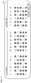
- White circles and black circles illustrated as the lighting pattern of the respective light emitting devices 50 indicate the turn-on period and the turn-off period, as in the description in FIG. 3 , and it is assumed that the time advances from the upper side to the lower side in the figure.
- the lighting pattern makes one round of turn-on, turn-off, turn-off, and turn-off, and then repeats the cycle of turn-on, turn-off, turn-off, and turn-off again.
- white circles or black circles having the same position in the vertical direction in the figure indicate the turn-on state or the turn-off state of each of the light emitting devices 50 at the same timing. For example, when the first light emitting device 50 is turned on, the second to fourth light emitting devices 50 are turned off, and the fifth light emitting device 50 is turned on.
- the start times of the second and subsequent light emitting devices 50 in the arrangement order are set on the basis of the start time of the first light emitting device 50 in the arrangement order by the function of the time calculation unit 21 c described above.
- the start time of the first light emitting device 50 in the arrangement order is determined as follows. That is, when a touch operation is performed on the “set” at the “start time” in the operation screen OP, the numerical value input in the frame F 3 is determined as the start time of the first light emitting device 50 in the arrangement order.
- a time obtained by adding a period TLg to a current time when the touch operation is performed on the portion labeled with the “determine” in the confirmation screen CF 1 is determined as the start time of the first light emitting device 50 in the arrangement order.
- the period TLg is a time required to transmit the start time and the lighting pattern (lighting information) to each of the light emitting devices 50 included in one group.
- the time required to transmit the start time and the lighting pattern to each of the 50 light emitting devices 50 is set as the period TLg.
- the lighting information including the start time and the lighting pattern calculated for each of the light emitting devices 50 included in the first group is transmitted to each of the light emitting devices 50 included in the first group by the function of the lighting control unit 21 d described above.
- the start time of first light emitting device 50 in the arrangement order will immediately come after transmission of the lighting information.
- the display of the user I/F unit 33 returns from the confirmation screen CF 1 to the operation screen OP.
- the operation screen OP and the setting screen SE are displayed again on the operation screen OP.
- FIG. 6A illustrates the turn-on and turn-off states of each of the light emitting devices 50 , which change in time series, when the second group is not cooperated with the first group.
- FIG. 6B illustrates the turn-on and turn-off states of each of the light emitting devices 50 , which change in time series, when the second group is cooperated with the first group.
- each of the first group and the second group is a group including the 50 light emitting devices 50 .
- the first (first) light emitting device 50 of the second group is arranged next to the 50 th (last) light emitting device 50 of the first group.
- the first light emitting device 50 of the second group is turned on and off in a lighting pattern started at a timing delayed by one period as compared with the lighting pattern of the light emitting device 50 arranged one before (the 50 th light emitting device 50 of the first group). For this reason, the lighting position is visually recognized as if it is moving in an order from the first to 50 th light emitting devices 50 of the first group and the first to 50 th light emitting devices 50 of the second group, one by one.
- Such a state is a state in which the first group and the second group cooperate with each other.
- the first light emitting device 50 of the second group is turned on and off in a lighting pattern started at a timing earlier by one period from the lighting pattern of the light emitting device 50 arranged one before (50 th light emitting device 50 of the first group). Therefore, the lighting position is visually recognized as if it is moving at a constant speed, from the first to 50 th light emitting devices 50 of the first group, but the lighting position moved to the 50 th light emitting device 50 of the first group is visually recognized as if it disappears without moving to the first light emitting device 50 of the second group.
- Such a state is a state in which the first group and the second group do not cooperate with each other.
- the operation screen OP in this case is a screen for setting the number of light emitting devices 50 included in the second group cooperating with the first group and the start time of each of the light emitting devices 50 .
- the operation screen OP for second-group setting is referred to as a second-group operation screen OP
- the operation screen OP for first-group setting is referred to as a first-group operation screen OP.
- a lighting pattern similar to the lighting pattern set in the first-group (configuration of the number of periods, the turn-on period, and the turn-off period) is set in each of the light emitting devices 50 , so that contents of the frame F 4 and the frame F 5 are fixed to the same contents as those set in the first-group operation screen OP, and no new input is received.
- the first-group operation screen OP when a touch operation is performed on either one of the portions displayed as the “auto” and the “manual” in the operation screen OP after 2 is input into the frame F 1 , broadcast transmission (information to be transmitted includes one unused channel) from the control device 10 to the plurality of light emitting devices 50 is executed.
- each of the light emitting devices 50 transmits device information to the control device 10 using the unused channel.
- the control unit 20 refers to the device information DB 40 a recorded in the recording medium 40 , and decides whether the light emitting device 50 of the first group is not included in the light emitting devices 50 that have transmitted the device information to the control device 10 .
- the light emitting device 50 of the first group is included, the light emitting device 50 is not included in the targets for collecting the device information (which is not regarded as the light emitting device 50 included in the second group).
- the unused channel used for communication with the light emitting device 50 is different from an unused channel used for communication with the first group.
- the wireless channel used when the control device 10 and each of the light emitting devices 50 included in an m-lth group communicate with each other is different from the wireless channel used when the control device 10 and each of the light emitting devices 50 included in an mth group communicate with each other.
- the wireless channel used when the control device 10 and each of the light emitting devices 50 included in the first group communicate with each other is different from the wireless channel used when the control device 10 and each of the light emitting devices 50 included in the second group communicate with each other. Therefore, the unused channels included in the information at the time of broadcast transmission from the control device 10 are different between the first group and the second group.
- the wireless channel used when each group and the control device 10 communicate with each other is different for each group, it is possible to prevent the lighting information indicating the start time and the lighting pattern transmitted from the control device 10 from being transmitted to a wrong group.
- the arrangement order of the light emitting devices 50 corresponding to the “number of light emitting devices” included in the group indicated by the “number indicating group of light emitting devices” is determined by the function of the arrangement order determination unit 21 b described above. After the arrangement order is determined, an input is made in the same portion as one of the “set” and the “not set” in the second-group operation screen OP in which the touch operation has been performed at the “start time” on the first-group operation screen OP.
- the “start time” is set in a state where nothing is input in the frame F 3 .
- the confirmation screen CF 2 is a screen for confirming contents set using the second-group operation screen OP.
- contents ranging from the contents of the first group to the contents of the group set using the second-group operation screen OP are displayed.
- the start times of the second and subsequent light emitting devices 50 in the arrangement order are set on the basis of the start time of the first light emitting device 50 in the arrangement order by the function of the time calculation unit 21 c described above.
- the start time of the first light emitting device 50 in the arrangement order is determined as follows.
- the control unit 20 which functions as the time calculation unit 21 c , calculates a start time T m 1 of the first light emitting device of the mth group by using the following formula (I), when each of the light emitting devices 50 included in the mth group is turned on in cooperation with the m-lth group after the lighting information is transmitted to each of the light emitting devices 50 included in the m-lth group (m is an arbitrary natural number of 2 or more).
- T m 1 T 1 1+ RT+nST (I)
- T 1 1 a start time of the first light emitting device 50 of first group
- T a length (seconds) of the turn-on period and the turn-off period
- R a remainder when the number of light emitting devices 50 included in the first to m ⁇ 1 th groups is divided by S.
- n an arbitrary natural number including 0
- T 1 1 is the start time of the first light emitting device 50 of the first group.
- the first light emitting device 50 of the first group starts the lighting pattern from the time indicated by T 1 1 .
- RT is a value indicating at least how many periods the first light emitting device 50 of the m th group should start the lighting pattern later than the start time (T 1 1 ) of the first light emitting device 50 of the first group.
- the start time (T 2 1 ) of the first light emitting device 50 of the second group is calculated using Formula (I)
- nST is a length of one cycle in the lighting pattern.
- n in nST is an arbitrary natural number including 0.
- the start time (T 2 1 ) of the first light emitting device 50 of the second group is calculated using Formula (I) will be described in detail.
- the number of light emitting devices 50 included in the first group is 50
- the first group to the m ⁇ 1 th group in the definition of R means the first group to the first group, and thus the number of light emitting devices 50 divided by S at this time is the number of light emitting devices 50 included in the first group.
- TLg a time required to transmit the lighting information to each of the light emitting devices 50 included in one group
- the condition A is that RT+nST is a natural number is imposed when n satisfying Formula (II) is calculated.
- the start time T m 1 is calculated by substituting n calculated in this manner into Formula (I).
- a minimum value, among values of n that satisfy Formula (II) and the condition A, is substituted into Formula (I).
- n is calculated by Formula (II), for example, in a case where the start time T 1 1 of the first light emitting device 50 of the first group is 10:00:00, a temporarily set start time T 2 1 P of the first light emitting device 50 of the second group is 10:15:00, and the period TLg is 30 seconds, the formula (10:15:00 ⁇ 10:00:00)+30 seconds ⁇ 2 ⁇ 0.3 (seconds)+n ⁇ 4 ⁇ 0.3 (seconds) is obtained when the numerical values are applied to Formula (II). Further calculation shows that n>774.5, and the minimum value of n at which RT+nST is a natural number is 777.
- the start time of the first light emitting device 50 of the second group is calculated using Formulas (I) and (II) and the condition A.
- n calculated using Formula (II) and the condition A is substituted into Formula (I)
- a time that is, time represented by X (hours):Y (minutes):Z (seconds):00
- T 1 1 is calculated as T m1 1 .
- the display of the user I/F unit 33 returns from the confirmation screen CF 2 to the operation screen OP, and the input in the numeric keypad NK will be reflected in the frame F 1 again.
- only an input of 1 or 3 is permitted in the frame F 1 .
- the third group is set such that the second group set on the previous operation screen OP and the third group set on the current operation screen OP cooperate with each other.
- the start time can be set so as to cooperate with the previous group. In a case where the numerical value of 1 is input in the frame F 1 , the start time can be set without considering cooperation with the previous group.
- the light emitting devices 50 arranged along the road are divided into groups, and the lighting pattern and the start time are set for each group.
- an upper limit of the number of light emitting devices 50 that can communicate with the control unit 20 at a time while the control unit 20 of the control device 10 executes the lighting control instruction 21 is 50. Therefore, for example, in a case of dividing the 100 light emitting devices 50 arranged along the road into two groups of 50 (the first group and the second group) and setting the start time such that the first group and the second group cooperate, it is necessary to transmit a signal indicating the setting contents to each of the first group and the second group.
- the operator carrying the control device 10 should perform the first-group setting around the first group and then move to the periphery of the second group to perform the second-group setting. Specifically, around the first group, 1 is input into the frame F 1 of the operation screen OP to perform various settings of the first group, and then, around the second group, 2 is input into the frame F 1 of the operation screen OP to perform various settings of the second group.
- the arrangement order of the light emitting devices 50 is determined on the basis of the device information. Therefore, the light emitting devices 50 can be easily turned on in the lighting pattern corresponding to the arrangement order of the light emitting devices 50 .
- the start time of the first light emitting device 50 of the mth group is calculated using Formula (I). Therefore, labor for the operator himself/herself to adjust the timing at which each of the last light emitting device 50 in the arrangement order in the m ⁇ 1 th group and the first light emitting device 50 in the arrangement order in the m th group starts repetition of the lighting pattern in order to turn on in cooperation with the m ⁇ 1 th group.
- the start times of the second and subsequent light emitting devices 50 of the mth group are calculated by adding T to the start time of the light emitting device 50 arranged one before the light emitting device 50 . Therefore, when the start time of the first light emitting device 50 of the m th group is calculated, the start times of the second and subsequent light emitting devices 50 of the same group can also be calculated.
- n an arbitrary natural number not including 0
- Formula (II) the calculated n is substituted into Formula (I) so that the start time of the light emitting device 50 is calculated. Therefore, it is possible to prevent the m-lth group and the mth group from being unable to cooperate with each other due to the fact that it takes time to transmit the lighting information to each of the light emitting devices 50 included in one group.
- the lighting setting process is executed when the light emitting devices 50 arranged along the road are divided into several groups and the lighting pattern and the start time are set for each group.
- the control unit 20 of the control device 10 receives an input of the number m indicating the group of the light emitting devices 50 (step S 105 ). Specifically, an input in the numeric keypad NK will be reflected in the frame F 1 of the operation screen OP.
- the control unit 20 receives an input of the number of light emitting devices 50 included in the group (step S 110 ). Specifically, a touch operation for selecting the “auto” or the “manual” on the operation screen OP or an input using the numeric keypad NK (input of a numerical value into the frame F 2 when the “manual” is selected) is received.
- the control unit 20 broadcast-transmits a transmission request for device information and information indicating the control device ID which is information for identifying the control device 10 , from the control device 10 to the plurality of light emitting devices 50 (step S 115 ).
- the information also includes one unused channel detected from among a plurality of wireless channels that can be used by the control device 10 .
- the control unit 20 collects device information including position information indicating each of the light emitting devices 50 from each of the light emitting devices 50 that have received the broadcast-transmitted information (step S 120 ).
- the collected device information is recorded in the recording medium 40 .
- the light emitting device ID is recorded with a corresponding an unused channel for use in communication with the light emitting device 50 indicated in the light emitting device ID.
- the number of light emitting devices 50 from which the device information is collected is determined according to which one of the “auto” and the “manual” in the operation screen in FIG. 4A has been touched.
- step S 125 the control unit 20 decides whether communication has been established. Specifically, after performing broadcast transmission (including information on an unused channel) in step S 115 , the control unit 20 decides whether communication has been established on the basis of whether there has been a return of device information from the light emitting device 50 using the unused channel.
- step S 125 NO
- the control unit 20 executes the process of step S 115 again. At this time, information indicating that communication has not been established may be displayed on the operation screen OP of FIG. 4A , and a selection screen for selecting whether to re-execute the collection of the device information may be displayed.
- step S 125 YES
- the number of light emitting devices 50 included in the group is input into a frame F 2 of the operation screen OP.
- step S 125 When the communication has been established (step S 125 : YES), by functioning as the arrangement order determination unit 21 b , the control unit 20 determines the arrangement order of the light emitting devices 50 on the basis of the collected device information. (Step S 130 ). The arrangement order is recorded in the RAM of the control device 10 .
- step S 130 After the arrangement order of the light emitting devices 50 is determined (step S 130 ), by functioning as the time calculation unit 21 c , the control unit 20 performs time calculation process, thereby setting the start time of each of the light emitting devices 50 included in the m th (number m input in step S 105 ) group (step S 140 ). Details of the time calculation process in step S 140 will be described with reference to FIG. 9 .
- the control unit 20 transmits the lighting information including the start time to each of the light emitting devices 50 (step S 150 ).
- the control unit 20 refers to the light emitting device ID recorded in the device information DB 40 a , and transmits the lighting information including the start time calculated for each of the light emitting devices 50 to each of the light emitting devices 50 via the wireless communication unit 31 .
- the lighting information includes the lighting pattern in addition to the start time.
- the time calculation process in step S 140 will be described in detail with reference to the flowchart illustrated in FIG. 9 .
- the time calculation process in step S 140 includes steps S 141 to S 149 which will be described below.
- the control unit 20 functions as the time calculation unit 21 c .
- the control unit 20 decides whether the m th group is a cooperating group (step S 141 ). Specifically, the control unit 20 refers to the number m input in the frame F 1 of the operation screen OP in step S 105 , and when the number m is 1, the group is decided to be a non-cooperating group, and when the number m is 2 or more, the group is decided to be a cooperating group.
- the cooperating group is a group cooperating with the previous group, and when the number m is 2, the second group cooperates with the first group.
- control unit 20 receives an input regarding the start time (the start time of the first light emitting device 50 of the first group) and the lighting pattern (step S 142 ). Specifically, a touch operation (selection of the “set” or the “not set”) for input into the frame F 3 of the first-group operation screen OP or an input using the numeric keypad NK (input of a numerical value into the frame F 3 when the “set” is selected) is received. In addition, inputs by the numeric keypad NK into the frame F 4 and the frame F 5 of the first-group operation screen OP and a touch operation on the setting screen SE are received.
- control unit 20 causes the user I/F unit 33 to display a confirmation screen (step S 143 ).
- the content of the screen displayed as the confirmation screen is a screen (confirmation screen CF 1 in FIG. 5 ) showing the contents of the first-group setting.
- the control unit 20 executes the next step S 144 .
- the control unit 20 sets the start time of each of the light emitting devices 50 included in the first group (step S 144 ). Specifically, when a touch operation is performed on the “set” at the “start time” in the first-group operation screen OP, the control unit 20 sets the numerical value input in the frame F 3 as the start time of the first light emitting device 50 in the arrangement order, and then sets the start times of the second and subsequent light emitting devices 50 in the arrangement order.
- the control unit 20 determines a time obtained by adding the period TLg to a current time when the touch operation is performed on the portion labeled with the “determine” in the confirmation screen as the start time of the first light emitting device 50 in the arrangement order, and then sets the start times of the second and subsequent light emitting devices 50 in the arrangement order.
- the start times of the second and subsequent light emitting devices 50 in the arrangement order are calculated by adding T to the start time of the light emitting device 50 arranged one before from the light emitting device 50 .
- the control unit 20 executes the process of step S 150 and subsequent steps in FIG. 8 .
- step S 145 the control unit 20 receives an input regarding the temporarily set start time (step S 145 ). Specifically, an input is made in the same portion as one of the “set” and the “not set” in the m th (m ⁇ 2)-group operation screen OP in which the touch operation has been performed at the “start time” on the m ⁇ 1 th -group operation screen OP.
- the portion is the “set”
- the input in the numeric keypad NK for inputting the temporarily set start time into the frame F 3 is received.
- the portion is the “not set”
- nothing is input into the frame F 3 .
- the control unit 20 causes the user I/F unit 33 to display a confirmation screen (step S 146 ).
- the contents of the screen displayed as the confirmation screen are screens (for example, the confirmation screen CF 2 in FIG. 7 ) indicating the setting contents of the first to m th groups.
- the control unit 20 executes the next step S 147 .
- the control unit 20 acquires various types of information (step S 147 ).
- the various types of information as used herein include the number of light emitting devices 50 included in the first group to m ⁇ 1 th group, the start time of the first light emitting device 50 of the first group, and the lighting pattern used for lighting of the m ⁇ 1 th group.
- the start time of each of the light emitting devices 50 included in the m th group is set (step S 149 ). Specifically, when a touch operation is performed on the “set” at the “start time” in the mth-group operation screen OP, the control unit 20 first calculates, as the start time of the first light emitting device 50 in the m th group, the minimum time satisfying Formula (I) among the times after the temporarily set start time input in the frame F 3 . The start times of the second and subsequent light emitting devices 50 in the arrangement order are then calculated by adding T to the start time of the light emitting device 50 arranged one before from the light emitting device 50 .
- the control unit 20 first sets, as the temporarily set start time, a current time when the touch operation is performed on the portion labeled with “enter” in the confirmation screen. Next, n satisfying Formula (II) and the condition A is calculated, and a minimum value, among the calculated values of n, is substituted into Formula (I) to calculate the start time of the first light emitting device 50 of the m th group. The start times of the second and subsequent light emitting devices 50 in the arrangement order are then calculated by adding T to the start time of the light emitting device 50 arranged one before from the light emitting device 50 . Thereafter, after finishing the time calculation process, the control unit 20 executes the process of step S 150 and subsequent steps in FIG. 8 .
- the lighting execution process is executed when the light emitting device 50 turns on and off the lighting unit 75 using the start time and the lighting pattern.
- the control unit 60 of the light emitting device 50 causes the GNSS reception unit 73 to receive a signal of the Global Navigation Satellite System (step S 205 ), and then, acquires position information indicating the position of the light emitting device 50 based on the output signal (step S 210 ).
- control unit 60 decides whether a transmission request for device information broadcast-transmitted from the control device 10 has been received (step S 215 ).
- the control unit 60 transmits the device information including the position information of the light emitting device 50 and the light emitting device ID to the control device 10 using one unused channel included in the broadcast-transmitted information (step S 220 ).
- the control unit 60 decides whether the lighting information including the start time and the lighting pattern transmitted from the control device 10 has been received via the wireless communication unit 71 (step S 225 ). When it is decided that the lighting information has been received (step S 225 : YES), the control unit 60 records the acquired lighting information in the lighting information DB 80 a.
- step S 230 the control unit 60 performs the lighting pattern execution process, thereby causing the lighting unit 75 to execute turn-on and turn-off according to the lighting pattern. Details of the lighting pattern execution process in step S 230 will be described with reference to FIG. 11 . After executing the lighting pattern execution process (S 230 ), the control unit 60 ends the lighting execution process.
- the lighting pattern execution process in step S 230 will be described in detail with reference to the flowchart illustrated in FIG. 11 .
- the time calculation process in step S 230 includes steps S 231 to S 237 which will be described below.
- the control unit 60 functions as the lighting execution unit 61 b .
- the control unit 60 of the light emitting device 50 reads the start time and the lighting pattern (step S 231 ).
- the control unit 60 refers to the lighting information DB 80 a recorded in the recording medium 80 and reads the start time and the lighting pattern.
- the control unit 60 decides whether the current time is the start time (step S 232 ). Specifically, the control unit 60 refers to a clocking circuit (not illustrated) included in the light emitting device 50 , and decides whether the current time is the start time. Then, when the current time is the start time (step S 232 : YES), the control unit 60 starts repetition of the lighting pattern and decides whether the current time corresponds to the turn-on period (step S 233 ). Specifically, the control unit 60 refers to the clocking circuit to calculate the time which has elapsed from the start time to the current time, and refers to the lighting pattern to decide whether the current time corresponds to the turn-on period or the turn-off period.
- step S 233 when the current time corresponds to the turn-on period (step S 233 : YES), the control unit 60 turns on the lighting unit 75 (step S 234 ), and when the current time corresponds to the turn-off period (step S 233 : NO), the control unit 60 turns off the lighting unit 75 (step S 235 ).
- step S 234 is executed in a state where the lighting unit 75 is turned on, the turn-on state is continued, and in a case where step S 235 is executed in a state where the lighting unit 75 is turned off, the turn-off state is continued.
- step S 234 or S 235 the control unit 60 decides whether an end signal instructing to end the lighting pattern has been received from the control device 10 (step S 236 ).
- step S 236 NO
- step S 243 the control unit 60 executes the process of step S 243 and subsequent steps again.
- step S 246 the control unit 60 turns off the lighting unit 75 (step S 247 ), ends the lighting pattern execution process (S 240 ), and then also ends the lighting execution process in FIG. 10 .
- the information collection unit only needs to be able to collect device information from a plurality of light emitting devices that are repeatedly turned on and off in a lighting pattern in which a turn-on period and a turn-off period within one cycle are defined.
- the lighting pattern is a pattern including four periods in which the length of one period is 0.3 seconds, in which the lighting unit is turned on and off in the order of the turn-on period continuing for 0.3 seconds and the turn-off period continuing for 0.9 seconds, but the embodiments of the present invention are not limited thereto.
- the length of one period may be different from 0.3 seconds, and the total number of the periods included in the lighting pattern may also be different from 4.
- the lighting pattern may be a pattern in which the turn-on period and the turn-off period having the same length are alternately repeated, or a proportion of the turn-on period in the lighting pattern may be higher than the proportion of the turn-off period.
- the lighting pattern is set by the frame F 4 and the frame F 5 of the operation screen OP and the setting screen SE, but the embodiments of the present invention are not limited thereto.
- predetermined 10 lighting patterns numbered may be recorded in advance in the control device 10 and each of the light emitting devices 50 , and the lighting pattern may be set by designating the predetermined lighting pattern number on the operation screen OP.
- the arrangement order determination unit only needs to be able to determine the arrangement order of the light emitting devices based on the device information.
- the arrangement order of the light emitting devices 50 is determined with reference to the correspondence table in which the numbers of the light emitting devices 50 (the numbers displayed on the surfaces of the cones in FIG. 1 ) and the light emitting devices ID are associated with each other, but the embodiments of the present invention are not limited thereto.
- the control device 10 has map information including data for specifying a shape of a road
- the road on which the light emitting devices 50 are arranged may be specified from the position of each of the light emitting devices 50
- the arrangement order of each of the light emitting devices 50 may be determined from the shape of the road.
- the arrangement order may be determined by specifying adjacent another light emitting device 50 for each of the light emitting devices 50 arranged along the road.
- Such adjacent another light emitting devices 50 are, for the light emitting device 50 arranged at an end position among the arranged light emitting devices 50 , another light emitting device 50 located closest to the light emitting device 50 , and, for the light emitting device 50 arranged at a position different from the end among the arranged light emitting devices 50 , another light emitting device 50 located closest to the light emitting device 50 and another light emitting device 50 located second closest thereto.
- the arrangement order can be determined by specifying any other adjacent light emitting device 50 for each of the light emitting devices 50 , and then numbering the light emitting devices 50 according to the order of adjacency from the light emitting device 50 arranged at an end position.
- the light emitting device 50 serving as the starting point may be designated by the operator via the user I/F unit 33 , or may be the light emitting device 50 located at a position closer to the control device 10 .
- the time calculation unit only needs to be able to calculate the start time at which each of the light emitting devices starts repetition of the lighting pattern using the arrangement order.
- the minimum value, among values of n satisfying Formula (II) and the condition A, is substituted into Formula (I), but the embodiments of the present invention are not limited thereto.
- a non-minimum value, among the calculated values of n may be substituted into Formula (I).
- n to be substituted into Formula (I) may be calculated using only Formula (II) without imposing the condition A.
- T m 1 a time (which is not necessarily X (hours):Y (minutes):Z (seconds):00) obtained by adding RT+nST (seconds) to T 1 1 is calculated as T m 1 .
- T m 1 T 1 1+ RT+nST (I) ( T m 1 P ⁇ T 1 1)+ TLg ⁇ RT+nST (II).
- n is calculated using a difference between the temporarily set start time T m 1 P of the first light emitting device 50 of the m th group and the start time T 1 1 of the first light emitting device 50 of the first group.
- n may be calculated using a difference between the temporarily set start time T m1 P of the first light emitting device 50 of the m th group and the start time T m-1 1 of the first light emitting device 50 in the m ⁇ 1 th group, as for Formula (IV).
- the condition A or a condition B (nST is a natural number) may be imposed.
- condition B may be imposed not only on Formula (IV) but also on Formulas (I), (II), and (III).
- R in the case of using Formulas (III) and (IV) is a remainder when the number of light emitting devices 50 included in the m ⁇ 1 th group is divided by S.
- the first start time of the second group is calculated using only Formula (I) in a case where an input is made to the “set” on the second-group operation screen OP, and the first start time of the second group is calculated using Formulas (I) and (II) in a case where an input is made to the “not set”.
- the embodiments of the present invention are not limited thereto.
- the first start time of the second group may be calculated using Formulas (I) and (II).
- the broadcast transmission is executed after the touch operation is performed on the “auto” in the operation screen OP, or after the touch operation to the “manual” and the input into the frame F 2 by the numeric keypad NK are performed and the determination key EK is input, but the embodiments of the present invention are not limited thereto.
- broadcast transmission may be executed and a value to be input into the frame F 2 may be determined.
- the start times of the second and subsequent light emitting devices 50 in the arrangement order are calculated by adding T to the start time of the light emitting device 50 arranged one before from the light emitting device 50 , but the embodiments of the present invention are not limited thereto.
- the start times of all the second and subsequent light emitting devices 50 included in the same group may be set to the same time as the start time of the first light emitting device 50 of the same group.
- the lighting information transmitted from the control device 10 to each of the light emitting devices 50 includes start period information indicating from which period of the periods included in the lighting pattern each of the light emitting devices 50 should be started the lighting pattern at the start time. For example, when the lighting pattern is set as illustrated in FIG.
- lighting information including start period information indicating that the lighting pattern is started from the first period (turn-on period) as the start period at the start time is transmitted to the first light emitting device 50 of the same group (see the first light emitting device of the first group in FIG. 6B ).
- lighting information including start period information indicating that the lighting pattern is started from the fourth period (turn-off period) as the start period at the start time is transmitted to the second light emitting device 50 of the same group (see the second light emitting device of the first group in FIG. 6B ).
- lighting information including start period information indicating that the lighting pattern is started from the third (second) period (turn-off period) as the start period at the start time is transmitted to the third (fourth) light emitting device 50 of the same group (see the third (fourth) light emitting device of the first group in FIG. 6B ). That is, the first period, among the periods included in the lighting pattern, is allocated to the start period indicated by the start period information of the first light emitting device 50 in the arrangement order, and the previous period to the period indicated as the start period of the light emitting device 50 arranged one before the light emitting device 50 is allocated to the start period indicated by the start period information of the second and subsequent light emitting devices 50 in the arrangement order as the start period.
- Each of the light emitting devices 50 included in one group from which the lighting information including such start period information has been received starts execution of the lighting pattern by the lighting unit 75 with the same time as the start time. Since the start periods indicated by the start period information received by the respective light emitting devices 50 are different from each other, each of the light emitting devices 50 can execute the lighting pattern at a timing delayed by one period as compared with the lighting pattern of the light emitting device 50 arranged one before (see the first group in FIG. 6B ).
- the method of determining the arrangement order of the light emitting devices on the basis of the device information can also be applied as instructions or a method.
- a change can be made as appropriate such that a part is software and a part is hardware.
- one or more embodiments of the present invention are also established as a recording medium storing instructions for controlling the device.
- the recording medium of the software may be a magnetic recording medium or a semiconductor memory, and can be considered exactly the same in any recording medium to be developed in the future.
Landscapes
- Engineering & Computer Science (AREA)
- Computer Networks & Wireless Communication (AREA)
- Circuit Arrangement For Electric Light Sources In General (AREA)
Abstract
Description
(T m1P−T 11)+TLg<RT+nST (II)
(T m1P−T 11)+TLg<RT+nST (II).
However, the embodiments of the present invention are not limited thereto. For example,
(T m1P−T m-11)+TLg<RT+nST (IV).
That is, in Formula (II), n is calculated using a difference between the temporarily set start time Tm 1P of the first
Claims (6)
T m1=T 11+RT+nST (I)
(T m1P−T 11)+TLg<RT+nST (II)
Applications Claiming Priority (3)
| Application Number | Priority Date | Filing Date | Title |
|---|---|---|---|
| JP2020191657A JP7545300B2 (en) | 2020-11-18 | 2020-11-18 | Control device, control method, and control program |
| JPJP2020-191657 | 2020-11-18 | ||
| JP2020-191657 | 2020-11-18 |
Publications (2)
| Publication Number | Publication Date |
|---|---|
| US20220159815A1 US20220159815A1 (en) | 2022-05-19 |
| US11375600B2 true US11375600B2 (en) | 2022-06-28 |
Family
ID=81587159
Family Applications (1)
| Application Number | Title | Priority Date | Filing Date |
|---|---|---|---|
| US17/454,890 Active US11375600B2 (en) | 2020-11-18 | 2021-11-15 | Control device, control method, and recording medium |
Country Status (2)
| Country | Link |
|---|---|
| US (1) | US11375600B2 (en) |
| JP (1) | JP7545300B2 (en) |
Families Citing this family (2)
| Publication number | Priority date | Publication date | Assignee | Title |
|---|---|---|---|---|
| JP7402920B2 (en) * | 2022-06-03 | 2023-12-21 | 名古屋電機工業株式会社 | Light-emitting device, light-emitting system, control device and program for light-emitting device |
| US12361824B2 (en) | 2023-07-27 | 2025-07-15 | Itron, Inc. | Control of street lights to indicate priority routes in smart cities |
Citations (5)
| Publication number | Priority date | Publication date | Assignee | Title |
|---|---|---|---|---|
| JPH10153975A (en) | 1996-09-25 | 1998-06-09 | Matsushita Electric Works Ltd | Line of sight guidance indicator system |
| US20050285508A1 (en) * | 2004-06-25 | 2005-12-29 | Chi Mei Optoelectronics Corp. | Color organic EL display and fabrication method thereof |
| US20060001033A1 (en) * | 2004-06-24 | 2006-01-05 | Kyocera Corporation | Image display |
| US20080239185A1 (en) * | 2007-03-30 | 2008-10-02 | Toshiro Takahashi | Active matrix display and method for producing the same |
| JP6372917B2 (en) | 2014-07-04 | 2018-08-15 | 名古屋電機工業株式会社 | Light emission control device, light emission control method, and light emission control system |
Family Cites Families (2)
| Publication number | Priority date | Publication date | Assignee | Title |
|---|---|---|---|---|
| US9179529B2 (en) | 2012-01-24 | 2015-11-03 | Joel R. Cessna | Optical pacing system and method |
| JP2016018231A (en) | 2014-07-04 | 2016-02-01 | 後藤 厚 | Indication system of indicator installed on road |
-
2020
- 2020-11-18 JP JP2020191657A patent/JP7545300B2/en active Active
-
2021
- 2021-11-15 US US17/454,890 patent/US11375600B2/en active Active
Patent Citations (5)
| Publication number | Priority date | Publication date | Assignee | Title |
|---|---|---|---|---|
| JPH10153975A (en) | 1996-09-25 | 1998-06-09 | Matsushita Electric Works Ltd | Line of sight guidance indicator system |
| US20060001033A1 (en) * | 2004-06-24 | 2006-01-05 | Kyocera Corporation | Image display |
| US20050285508A1 (en) * | 2004-06-25 | 2005-12-29 | Chi Mei Optoelectronics Corp. | Color organic EL display and fabrication method thereof |
| US20080239185A1 (en) * | 2007-03-30 | 2008-10-02 | Toshiro Takahashi | Active matrix display and method for producing the same |
| JP6372917B2 (en) | 2014-07-04 | 2018-08-15 | 名古屋電機工業株式会社 | Light emission control device, light emission control method, and light emission control system |
Also Published As
| Publication number | Publication date |
|---|---|
| US20220159815A1 (en) | 2022-05-19 |
| JP7545300B2 (en) | 2024-09-04 |
| JP2022080530A (en) | 2022-05-30 |
Similar Documents
| Publication | Publication Date | Title |
|---|---|---|
| US11375600B2 (en) | Control device, control method, and recording medium | |
| EP2894948B1 (en) | Control method for mobile device | |
| TWI418389B (en) | Radio control transmitter and method for communication in the same | |
| CN113225673B (en) | Vehicle searching method, device and system | |
| US20110043539A1 (en) | Map Display Device | |
| EP3174303B1 (en) | Remote control method for multi-terminal device, and related apparatus and system | |
| EP3716677A1 (en) | Optimization system for distributed antenna system | |
| DE102012110099B3 (en) | Prediction unit for traffic light system utilized for traffic control of road users, has control unit, where prediction result is determined in form of data that is provided as original data for other road users over interface | |
| WO2021052390A1 (en) | Bluetooth beacon configuration method, signal transceiving apparatus, personal mobile terminal and readable storage medium | |
| CN114501325B (en) | Indoor navigation method and device, electronic equipment and storage medium | |
| KR101452428B1 (en) | System and method for lamp managment | |
| JP5938917B2 (en) | Computer program, portable information processing device, traffic signal controller and traffic signal control system | |
| EP1981011A2 (en) | Method and apparatus for providing help | |
| US20220057619A1 (en) | Digital microscope system, method for operating the same and computer program | |
| CN106790424B (en) | Timing control method, client, server and timing control system | |
| JP6807429B2 (en) | Signal control device | |
| JP5347865B2 (en) | Traffic signal information providing system, signal control device, and information providing device | |
| JP7402920B2 (en) | Light-emitting device, light-emitting system, control device and program for light-emitting device | |
| JP2016219024A (en) | Recognition device, control method, program and recording medium for traffic signal | |
| EP3843330A1 (en) | Method for setting control function, control device and control system | |
| JP5741650B2 (en) | Traffic signal information providing system, signal control device, and information providing device | |
| JP7329465B2 (en) | Block division study system and block division study method | |
| US6751461B1 (en) | Apparatus and method for operating a communication unit using a default channel | |
| CN112051561A (en) | Distance measurement method and device | |
| JP4246549B2 (en) | FPU remote control system |
Legal Events
| Date | Code | Title | Description |
|---|---|---|---|
| FEPP | Fee payment procedure |
Free format text: ENTITY STATUS SET TO UNDISCOUNTED (ORIGINAL EVENT CODE: BIG.); ENTITY STATUS OF PATENT OWNER: LARGE ENTITY |
|
| AS | Assignment |
Owner name: NAGOYA ELECTRIC WORKS CO., LTD., JAPAN Free format text: ASSIGNMENT OF ASSIGNORS INTEREST;ASSIGNORS:TANAKA, ATSUSHI;SENGOKU, HIROAKI;MIYAGAWA, KOJI;REEL/FRAME:058384/0337 Effective date: 20211013 |
|
| STPP | Information on status: patent application and granting procedure in general |
Free format text: PUBLICATIONS -- ISSUE FEE PAYMENT RECEIVED |
|
| STPP | Information on status: patent application and granting procedure in general |
Free format text: PUBLICATIONS -- ISSUE FEE PAYMENT VERIFIED |
|
| STCF | Information on status: patent grant |
Free format text: PATENTED CASE |