US11373620B2 - Calibration device and calibration method for display panel brightness uniformity - Google Patents
Calibration device and calibration method for display panel brightness uniformity Download PDFInfo
- Publication number
- US11373620B2 US11373620B2 US17/078,141 US202017078141A US11373620B2 US 11373620 B2 US11373620 B2 US 11373620B2 US 202017078141 A US202017078141 A US 202017078141A US 11373620 B2 US11373620 B2 US 11373620B2
- Authority
- US
- United States
- Prior art keywords
- mode
- brightness
- value
- values
- component
- Prior art date
- Legal status (The legal status is an assumption and is not a legal conclusion. Google has not performed a legal analysis and makes no representation as to the accuracy of the status listed.)
- Active
Links
Images


Classifications
-
- G—PHYSICS
- G09—EDUCATION; CRYPTOGRAPHY; DISPLAY; ADVERTISING; SEALS
- G09G—ARRANGEMENTS OR CIRCUITS FOR CONTROL OF INDICATING DEVICES USING STATIC MEANS TO PRESENT VARIABLE INFORMATION
- G09G5/00—Control arrangements or circuits for visual indicators common to cathode-ray tube indicators and other visual indicators
- G09G5/10—Intensity circuits
-
- G—PHYSICS
- G09—EDUCATION; CRYPTOGRAPHY; DISPLAY; ADVERTISING; SEALS
- G09G—ARRANGEMENTS OR CIRCUITS FOR CONTROL OF INDICATING DEVICES USING STATIC MEANS TO PRESENT VARIABLE INFORMATION
- G09G2320/00—Control of display operating conditions
- G09G2320/02—Improving the quality of display appearance
- G09G2320/0233—Improving the luminance or brightness uniformity across the screen
-
- G—PHYSICS
- G09—EDUCATION; CRYPTOGRAPHY; DISPLAY; ADVERTISING; SEALS
- G09G—ARRANGEMENTS OR CIRCUITS FOR CONTROL OF INDICATING DEVICES USING STATIC MEANS TO PRESENT VARIABLE INFORMATION
- G09G2320/00—Control of display operating conditions
- G09G2320/02—Improving the quality of display appearance
- G09G2320/0271—Adjustment of the gradation levels within the range of the gradation scale, e.g. by redistribution or clipping
- G09G2320/0276—Adjustment of the gradation levels within the range of the gradation scale, e.g. by redistribution or clipping for the purpose of adaptation to the characteristics of a display device, i.e. gamma correction
-
- G—PHYSICS
- G09—EDUCATION; CRYPTOGRAPHY; DISPLAY; ADVERTISING; SEALS
- G09G—ARRANGEMENTS OR CIRCUITS FOR CONTROL OF INDICATING DEVICES USING STATIC MEANS TO PRESENT VARIABLE INFORMATION
- G09G2320/00—Control of display operating conditions
- G09G2320/02—Improving the quality of display appearance
- G09G2320/0285—Improving the quality of display appearance using tables for spatial correction of display data
-
- G—PHYSICS
- G09—EDUCATION; CRYPTOGRAPHY; DISPLAY; ADVERTISING; SEALS
- G09G—ARRANGEMENTS OR CIRCUITS FOR CONTROL OF INDICATING DEVICES USING STATIC MEANS TO PRESENT VARIABLE INFORMATION
- G09G2320/00—Control of display operating conditions
- G09G2320/02—Improving the quality of display appearance
- G09G2320/029—Improving the quality of display appearance by monitoring one or more pixels in the display panel, e.g. by monitoring a fixed reference pixel
-
- G—PHYSICS
- G09—EDUCATION; CRYPTOGRAPHY; DISPLAY; ADVERTISING; SEALS
- G09G—ARRANGEMENTS OR CIRCUITS FOR CONTROL OF INDICATING DEVICES USING STATIC MEANS TO PRESENT VARIABLE INFORMATION
- G09G2320/00—Control of display operating conditions
- G09G2320/06—Adjustment of display parameters
- G09G2320/0693—Calibration of display systems
-
- G—PHYSICS
- G09—EDUCATION; CRYPTOGRAPHY; DISPLAY; ADVERTISING; SEALS
- G09G—ARRANGEMENTS OR CIRCUITS FOR CONTROL OF INDICATING DEVICES USING STATIC MEANS TO PRESENT VARIABLE INFORMATION
- G09G2360/00—Aspects of the architecture of display systems
- G09G2360/16—Calculation or use of calculated indices related to luminance levels in display data
Definitions
- the present disclosure relates to a calibration device and calibration method, especially to a calibration device and calibration method for display panel brightness uniformity.
- a conventional art When calibrating the brightness uniformity of a display panel in each kind of display modes, a conventional art will take photos of the screen of the display panel under different kinds of display setting including red-screen setting, green-screen setting, blue-screen setting, and different kinds of brightness setting for each kind of the display modes so that a calibrating system can used these photos to calibrate different display regions of the display panel for brightness uniformity. If there are a lot of kinds of display modes and a lot of kinds of brightness setting, it will take a lot of time to take photos and the overall time for the calibration will be very long, which is disadvantageous to the production cost.
- An object of the present disclosure is to provide a calibration device and calibration method for display panel brightness uniformity. Compared with the prior art, the calibration device and calibration method are more efficient in productivity.
- An embodiment of the calibration device of the present disclosure can generate second mode calibration data of a second mode according to known first mode calibration data of a first mode.
- This embodiment includes a storage circuit, a mode brightness calculating circuit, a target brightness ratio calculating circuit, a target brightness calculating circuit, an interpolating circuit, and a gain calculating circuit.
- the storage circuit is configured to store the first mode calibration data and reference data, in which the first mode calibration data include a first mode measured brightness value and K sets of maximum brightness values of a display region, the display region is one of multiple display regions of a display panel, the K sets of maximum brightness values are based on K sets of red, green, and blue (RGB) input values, each set of the K sets of maximum brightness values includes a red-component maximum brightness value, a green-component maximum brightness value, and a blue-component maximum brightness value, the reference data include a second ratio of a second mode measured brightness value to the first mode measured brightness value and a set of second mode reference brightness values, and the set of second mode reference brightness values includes a second mode red-component reference brightness value, a second mode green-component reference brightness value, and a second mode blue-component reference brightness value.
- the first mode calibration data include a first mode measured brightness value and K sets of maximum brightness values of a display region
- the display region is one of multiple display regions of a display panel
- the mode brightness calculating circuit is configured to calculate a second mode brightness value according to the first mode measured brightness value and the second ratio.
- the target brightness ratio calculating circuit is configured to calculate a second mode target brightness ratio according to a target brightness setting value and the second mode brightness value.
- the target brightness calculating circuit is configured to calculate a second mode red-component target brightness value according to the second mode red-component reference brightness value and the second mode target brightness ratio, calculate a second mode green-component target brightness value according to the second mode green-component reference brightness value and the second mode target brightness ratio, and calculate a second mode blue-component target brightness value according to the second mode blue-component reference brightness value and the second mode target brightness ratio.
- the colored-component brightness calculating circuit is configured to calculate K second mode red-component brightness values according to the K red-component maximum brightness values of the K sets of maximum brightness values, calculate K second mode green-component brightness values according to the K green-component maximum brightness values of the K sets of maximum brightness values, and calculate K second mode blue-component brightness values according to the K blue-component maximum brightness values of the K sets of maximum brightness values.
- the interpolating circuit is configured to generate a second mode red-brightness characteristic curve according to the K second mode red-component brightness values, generate a second mode green-brightness characteristic curve according to the K second mode green-component brightness values, and generate a second mode blue-brightness characteristic curve according to the K second mode blue-component brightness values.
- the gain calculating circuit is configured to calculate a second mode red-brightness gain according to the second mode red-component target brightness value and the second mode red-brightness characteristic curve, calculate a second mode green-brightness gain according to the second mode green-component target brightness value and the second mode green-brightness characteristic curve, and calculate a second mode blue-brightness gain according to the second mode blue-component target brightness value and the second mode blue-brightness characteristic curve, wherein the K second mode red-brightness gain, the K second mode green-brightness gain, and the K second mode blue-brightness gain are used as the second mode calibration data for calibrating the brightness of the display region in the second mode, and the K is an integer greater than one.
- An embodiment of the method of the present disclosure can generate second mode calibration data of a second mode according to known first mode calibration data of a first mode.
- This embodiment includes the following steps: providing the first mode calibration data and reference data, in which the first mode calibration data include a first mode measured brightness value and K set(s) of maximum brightness values of a display region, the display region is one of multiple display regions of a display panel, the reference data include a second ratio of a second mode measured brightness value to the first mode measured brightness value and a set of second mode reference brightness values, and the K is a positive integer; calculating a second mode brightness value according to the first mode measured brightness value and the second ratio; calculating a second mode target brightness ratio according to a target brightness setting value and the second mode brightness value; calculating a set of second mode target brightness values according to the set of second mode reference brightness values and the second mode target brightness ratio; calculating K set(s) of second mode colored-component brightness values according to the K set(s) of maximum brightness values; generating X second mode brightness characteristic curve(
- FIG. 1 shows the calibration device for display panel brightness uniformity according to an embodiment of the present disclosure.
- FIG. 2 a shows brightness characteristic curves of different display regions of the same display panel.
- FIG. 2 b shows a red-component/green-component/blue-component brightness characteristic curve of a display region.
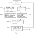
- FIG. 3 shows an embodiment of the procedures executed by the calibration device of FIG. 1 .
- FIG. 4 shows the calibration method for display panel brightness uniformity according to an embodiment of the present disclosure.
- the present disclosure discloses a calibration device and calibration method for display panel brightness uniformity.
- the calibration device and calibration method can deduce unknown calibration data from known calibration data; more specifically, the calibration device and calibration method can generate calibration data of other display modes according to known first mode calibration data of a first mode quickly. Accordingly, the whole calibration process can be accelerated, and the production yield can be raised.
- FIG. 1 shows an embodiment of the calibration device of the present disclosure.
- the calibration device 100 of FIG. 1 is configured to calibrate different display regions of a display panel for brightness uniformity, and includes a storage circuit 110 , a mode brightness calculating circuit 120 , a target brightness ratio calculating circuit 130 , a target brightness calculating circuit 140 , a colored-component brightness calculating circuit 150 , an interpolating circuit 160 , and a gain calculating circuit 170 .
- Some or all of the circuits 120 - 170 in FIG. 1 can be integrated into a single circuit in accordance with the demand for implementation.
- each circuit in FIG. 1 alone can be realized with known or self-developed techniques.
- the storage circuit 110 is configured to store the first mode calibration data and reference data.
- the display region is one of S display regions of the display panel, and thus the first mode calibration data may further include K sets of maximum brightness values of each of the other (S-1) display region(s) so that the calibration device 100 can generate the calibration data for the (S-1) display region(s) in a similar manner, wherein S is an integer greater than one.
- Each set of the K sets of maximum brightness values includes a red-component maximum brightness value (RY max ), a green-component maximum brightness value (GY max ), and a blue-component maximum brightness value (BY max ), and therefore the K sets of maximum brightness values include K red-component maximum brightness values, K green-component maximum brightness values, and K blue-component maximum brightness values.
- the reference data stored in the storage circuit 110 include a second ratio (Ratio_2) of a second mode measured brightness value (e.g., the maximum brightness value of the center of the display panel measured by a known color calibration apparatus in a second mode (e.g, specific color temperature mode/print color management (PCM) mode)) to the first mode measured brightness value
- a second mode measured brightness value e.g., the maximum brightness value of the center of the display panel measured by a known color calibration apparatus in a second mode (e.g, specific color temperature mode/print color management (PCM) mode
- the mode brightness calculating circuit 120 is configured to calculate a second mode brightness value (Lv2) according to the first mode measured brightness value (Lv1) and the second ratio (Ratio_2).
- the above-mentioned “Ratio_1” is a first ratio of the first mode measured brightness value to a reference mode measured brightness value (e.g., the maximum measured brightness value)
- Ratio_ ⁇ 1 first ⁇ ⁇ mode ⁇ ⁇ measured ⁇ ⁇ brightness ⁇ ⁇ ⁇ value reference ⁇ ⁇ mode ⁇ ⁇ measured ⁇ ⁇ brightness ⁇ ⁇ value
- the first ratio can be included in the first mode calibration data according to the demand for implementation optionally.
- the second ratio is smaller than one (i.e., Ratio_2 ⁇ 1).
- the target brightness ratio calculating circuit 130 is configured to calculate a second mode target brightness ratio (targetRatio2) according to a target brightness setting value (targetLv) and the second mode brightness value (Lv2).
- targetLv target brightness setting value
- Lv2 second mode brightness value
- the target brightness setting value can be included in the aforementioned reference data or provided by a user input or any of other sources.
- the colored-component brightness calculating circuit 150 is configured to calculate K second mode red-component brightness values (i.e., K RY2s that are based on the aforementioned K sets of RGB input values), calculate K second mode green-component brightness values (i.e., K GY2s that are based on the K sets of RGB input values), and calculate K second mode blue-component brightness values (i.e., K BY2s that are based on the K sets of RGB input values).
- K second mode red-component brightness values i.e., K RY2s that are based on the aforementioned K sets of RGB input values
- K second mode green-component brightness values i.e., K GY2s that are based on the K sets of RGB input values
- K second mode blue-component brightness values i.e., K BY2s that are based on the K sets of RGB input values
- the RY2, GY2, and BY2 based on each set of RGB input values are obtained with the following equations:
- gamma2 is the gamma value of the second mode dependent on the given characteristic of the second mode
- the interpolating circuit 160 is configured to perform interpolation and/or extrapolation according to the K second mode red-component brightness values (i.e., K RY2s that are based on the K sets of RGB input values) and thereby generate a second mode red brightness characteristic curve, perform interpolation and/or extrapolation according to the K second mode green-component brightness values (i.e., K GY2s that are based on the K sets of RGB input values) and thereby generate a second mode green brightness characteristic curve, and perform interpolation and/or extrapolation according to the K second mode blue-component brightness values (i.e., K BY2s that are based on the K sets of RGB input values) and thereby generate a second mode blue brightness characteristic curve.
- K BY2s that are based on the K sets of RGB input values
- the interpolating circuit 160 generates three characteristic curves for each display region, and each curve can be used to find out an output value in accordance with an input value. More specifically, each characteristic curve is indicative of the relationship between the input values and the output values in regard to the characteristic curve itself; the range of the input values (e.g., 128-255 including K original red/green/blue input values) concerning each characteristic curve can be determined according to the demand for implementation, and the output values concerning each characteristic curve includes K RY2s/K GY2s/K BY2s generated by the colored-component brightness calculating circuit 150 .
- the gain calculating circuit 170 is configured to calculate a second mode red brightness gain (Gain2_R) according to the second mode red-component target brightness value (i.e., the aforementioned targetRY2) and the second mode red brightness characteristic curve, calculate a second mode green brightness gain (Gain2_G) according to the second mode green-component target brightness value (i.e., the aforementioned targetGY2) and the second mode green brightness characteristic curve, and calculate a second mode blue brightness gain (Gain2_B) according to the second mode blue-component target brightness value (i.e., the aforementioned targetBY2) and the second mode blue brightness characteristic curve.
- a second mode red brightness gain Gain2_R
- the second mode red-component target brightness value i.e., the aforementioned targetRY2
- a second mode red brightness characteristic curve calculate a second mode green brightness gain (Gain2_G) according to the second mode green-component target brightness value (i.e., the aforementioned targetGY
- the second mode red, green, and blue brightness gains are stored in the storage circuit 110 and used as the second mode calibration data for calibrating the aforementioned display region in the second mode for brightness uniformity.
- FIG. 2 a shows the brightness characteristic curves (horizontal axis: input code; vertical axis: output brightness) of multiple display regions 200 of the aforementioned display panel.
- FIG. 2 b shows an exemplary red-component/green-component/blue-component brightness characteristic curve (horizontal axis: input code; vertical axis: red/green/blue brightness) of any of the multiple display regions 200 .
- People of ordinary skill in the art can refer to FIGS. 2 a -2 b and the preceding disclosure to appreciate that in regard to each set of RGB input values the Gain2_R is equal to “the input code of the second mode red brightness characteristic curve corresponding to targetRY2” divided by “the maximum red input brightness value 255”
- the Gain2_G is equal to “the input code of the second mode green brightness characteristic curve corresponding to targetGY2” divided by “the maximum green input brightness value 255”
- Gain2 - ⁇ G input ⁇ ⁇ code - ⁇ targetGY ⁇ 2 2 ⁇ 5 ⁇ 5 )
- the Gain2_B is equal to “the input code of the second mode blue brightness characteristic curve corresponding to targetBY2” divided by “the maximum blue input brightness value 255”
- Gain2 - ⁇ B input ⁇ ⁇ code - ⁇ targetBY ⁇ 2 2 ⁇ 5 ⁇ 5 ) , Accordingly, provided the Gain2_R/Gain2_G/Gain2_B of a display region of the display panel is
- FIG. 3 shows an embodiment of the procedures executed by the calibration device 100 of FIG. 1 for the brightness calibration of every display region of the aforementioned display panel.
- the procedures of FIG. 3 include:
- FIG. 4 shows an embodiment of the calibration method of the present disclosure for display panel brightness uniformity.
- This embodiment can generate second mode calibration data according to known first mode calibration data, and includes the following steps:
- the calibration device and calibration method of the present disclosure can quickly generate second mode calibration data according to known first mode calibration data, and thereby accelerate the whole process of calibration and improve the production efficiency.
Abstract
Description
The reference data further include a set of second mode reference brightness values (e.g., a set of second mode maximum brightness values (RY2255(center), GY2255(center), BY2255(center)) of the central display region of the display panel in the second mode, in which the central display region is one of the aforementioned S display regions), and the set of second mode reference brightness values is based on a set of second mode predetermined RGB input values (e.g., (R, G, B)=(255, 255, 255)) including a second mode red-component reference brightness value (RY2REF), a second mode green-component reference brightness value (GY2REF), and a second mode blue-component reference brightness value (BY2REF). It should be noted that the way to obtain the first mode calibration data and the reference data can be a known technique as mentioned in the description of related art of this specification or a self-developed technique, and such known or self-developed technique falls beyond the scope of the present invention.
and the first ratio can be included in the first mode calibration data according to the demand for implementation optionally. In the embodiment of
in which “gamma2” is the gamma value of the second mode dependent on the given characteristic of the second mode, and this gamma value can be determined in advance, stored in the
the Gain2_G is equal to “the input code of the second mode green brightness characteristic curve corresponding to targetGY2” divided by “the maximum green input brightness value 255”
and the Gain2_B is equal to “the input code of the second mode blue brightness characteristic curve corresponding to targetBY2” divided by “the maximum blue input brightness value 255”
Accordingly, provided the Gain2_R/Gain2_G/Gain2_B of a display region of the display panel is
and the Gain2_R/Gain2_G/Gain2_B of another display region of the display panel is
when both the input signals for the two different display regions are indicative of the maximum red/green/blue input brightness values (i.e., 255), the output brightness values (i.e., input value×Gain) of the two different display regions will be
respectively, and therefore the output brightness values (i.e., targetRY2s/targetGY2s/targetBY2s) of the two different display regions are the same and the brightness uniformity of the two different display regions is realized.
- S310: if a current mode is the Mth mode and M≤N, making M=M+1, wherein both the M and the N are positive integers, and the N is a total number of display panel modes under consideration.
- S320: calculating K sets of colored-component brightness values of the Mth mode (e.g., K red-component brightness values of the Mth mode (RYM), K green-component brightness values of the Mth mode (GYM), and K blue-component brightness values of the Mth mode (BYM)) according to pre-stored K sets of maximum brightness values that are based on K sets of input values respectively.
- S330: calculating an Mth mode brightness value (LvM) according to a pre-stored first mode measured brightness value (Lv1) and an Mth ratio (Ratio_M).
- S340: generating an Mth mode brightness characteristic curve of each color according to the K sets of colored-component brightness values of the Mth mode.
- S350: calculating an Mth mode target brightness ratio (targetRatioM) according to a pre-stored target brightness setting value (targetLv) and the Mth mode brightness value; and calculating a set of target brightness values of the Mth mode (e.g., the Mth mode red-component target brightness value (targetRYM), the Mth mode green-component target brightness value (targetGYM), and the Mth mode blue-component target brightness value (targetBYM)) according to a set of reference brightness values of the Mth mode and the Mth mode target brightness ratio.
- S360: calculating the Mth mode brightness gain of each color according to the set of target brightness values of the Mth mode and the Mth mode brightness characteristic curve; and storing the Mth mode brightness gain of each color.
- S370: if the current mode is the Mth mode and M=N, ending the procedures; or else returning to S310.
- S410: providing the first mode calibration data stored in advance and providing reference data, in which the first mode calibration data include a first mode measured brightness value and K set(s) of maximum brightness values of a display region, the display region is one of multiple display regions of a display panel, the reference data include a second ratio of a second mode measured brightness value to the first mode measured brightness value and a set of second mode reference brightness values, and the K is a positive integer. This step can be carried out by the
storage circuit 110 ofFIG. 1 or the equivalent thereof. - S420: calculating a second mode brightness value according to the first mode measured brightness value and the second ratio. This step can be carried out by the calculating
circuit 120 ofFIG. 1 or the equivalent thereof. - S430: calculating a second mode target brightness ratio according to a target brightness setting value and the second mode brightness value. This step can be carried out by the calculating
circuit 130 ofFIG. 1 or the equivalent thereof. - S440: calculating a set of second mode target brightness values, that is to say X second mode brightness value(s) being representative of X color(s) respectively, according to the set of second mode reference brightness values and the second mode target brightness ratio. This step can be carried out by the calculating
circuit 140 ofFIG. 1 or the equivalent thereof. - S450: calculating K set(s) of second mode colored-component brightness values according to the K set(s) of maximum brightness values; and then generating X second mode brightness characteristic curve(s) according to the K set(s) of second mode colored-component brightness values, in which the X is a positive integer. This step can be carried out by the calculating
circuit 150 and the interpolatingcircuit 160 ofFIG. 1 or the equivalent thereof. - S460: calculating X second mode brightness gain(s) according to the set of second mode target brightness values and the X second mode brightness characteristic curve(s), in which the X second mode brightness gain(s) are used as the second mode calibration data for calibrating the brightness of the display region in the second mode. This step can be carried out by the calculating
circuit 170 ofFIG. 1 or the equivalent thereof.
Claims (16)
Applications Claiming Priority (2)
| Application Number | Priority Date | Filing Date | Title |
|---|---|---|---|
| CN201911030167.1 | 2019-10-28 | ||
| CN201911030167.1A CN112735353B (en) | 2019-10-28 | 2019-10-28 | Screen brightness uniformity correction device and method |
Publications (2)
| Publication Number | Publication Date |
|---|---|
| US20210125579A1 US20210125579A1 (en) | 2021-04-29 |
| US11373620B2 true US11373620B2 (en) | 2022-06-28 |
Family
ID=73644013
Family Applications (1)
| Application Number | Title | Priority Date | Filing Date |
|---|---|---|---|
| US17/078,141 Active US11373620B2 (en) | 2019-10-28 | 2020-10-23 | Calibration device and calibration method for display panel brightness uniformity |
Country Status (3)
| Country | Link |
|---|---|
| US (1) | US11373620B2 (en) |
| CN (1) | CN112735353B (en) |
| TW (1) | TWI703555B (en) |
Citations (24)
| Publication number | Priority date | Publication date | Assignee | Title |
|---|---|---|---|---|
| US20040196250A1 (en) * | 2003-04-07 | 2004-10-07 | Rajiv Mehrotra | System and method for automatic calibration of a display device |
| US20070052735A1 (en) * | 2005-08-02 | 2007-03-08 | Chih-Hsien Chou | Method and system for automatically calibrating a color display |
| US20070146266A1 (en) * | 2003-10-23 | 2007-06-28 | Tetsuya Yasuda | Display characteristics calibration method, display characteristics calibration apparatus, and computer program |
| US7330190B2 (en) * | 2001-12-21 | 2008-02-12 | Sharp Kabushiki Kaisha | Correction characteristic determining device, correction characteristic determining method, and display device |
| US20090207182A1 (en) * | 2008-02-15 | 2009-08-20 | Naoki Takada | Display Device |
| US20120147161A1 (en) * | 2010-12-10 | 2012-06-14 | Kim Kiltae | Stereoscopic image display and driving method thereof |
| US20120293400A1 (en) * | 2011-05-20 | 2012-11-22 | Canon Kabushiki Kaisha | Image display system, image display apparatus and calibration method |
| US20140307007A1 (en) * | 2013-04-11 | 2014-10-16 | Lg Display Co., Ltd. | Electronic device, display controlling apparatus and method thereof |
| US20150310798A1 (en) * | 2014-03-18 | 2015-10-29 | Nvidia Corporation | Superresolution display using cascaded panels |
| US20150317928A1 (en) * | 2014-05-02 | 2015-11-05 | Qualcomm Incorporated | Mobile device based color management of digital displays |
| US20160189590A1 (en) * | 2014-12-31 | 2016-06-30 | Shenzhen China Star Optoelectronics Technology Co., Ltd. | Method for setting parameters of a display panel and device therefor |
| US20160260368A1 (en) * | 2014-06-23 | 2016-09-08 | Shenzhen China Star Optoelectronics Technology Co., Ltd. | A method for correcting gray-scale of display panel |
| US20170103694A1 (en) * | 2015-10-12 | 2017-04-13 | Samsung Electronics Co., Ltd. | Electronic apparatus, method of calibrating display panel apparatus, and calibration system |
| US9800793B2 (en) * | 2016-01-14 | 2017-10-24 | Realtek Semiconductor Corp. | Method for generating target gain value of wide dynamic range operation |
| US20170316754A1 (en) * | 2014-10-03 | 2017-11-02 | Sharp Kabushiki Kaisha | Image processing device, display device, position determining device, position determining method, and recording medium |
| US20180225075A1 (en) * | 2015-08-04 | 2018-08-09 | Samsung Electronics Co., Ltd. | Display device including plurality of modules and control method therefor |
| US20190172186A1 (en) * | 2017-12-04 | 2019-06-06 | Realtek Semiconductor Corporation | Image tuning device and method |
| US20190251929A1 (en) * | 2016-10-20 | 2019-08-15 | Hewlett-Packard Development Company, L.P. | Displays having calibrators |
| US20200098333A1 (en) * | 2018-09-26 | 2020-03-26 | Apple Inc. | Method and System for Display Color Calibration |
| US20200126498A1 (en) * | 2018-10-23 | 2020-04-23 | Wistron Corp. | Display apparatus and color-calibration method thereof |
| US20200210366A1 (en) * | 2018-05-04 | 2020-07-02 | Intel Corporation | Flex bus protocol negotiation and enabling sequence |
| US10777168B2 (en) * | 2018-11-16 | 2020-09-15 | Chengdu Boe Optoelectronics Technology Co., Ltd. | Display panel, display device, and method for adjusting display panel |
| US10825375B1 (en) * | 2019-04-17 | 2020-11-03 | Shenzhen Yunyinggu Technology Co., Ltd. | Method and system for determining grayscale mapping correlation in display panel |
| US20200365113A1 (en) * | 2019-05-16 | 2020-11-19 | Diva Laboratories, Ltd. | Ubiquitous auto calibration device and the calibration method thereof |
Family Cites Families (10)
| Publication number | Priority date | Publication date | Assignee | Title |
|---|---|---|---|---|
| US7515128B2 (en) * | 2004-03-15 | 2009-04-07 | Philips Solid-State Lighting Solutions, Inc. | Methods and apparatus for providing luminance compensation |
| CN101908329B (en) * | 2009-06-05 | 2012-11-07 | 瑞昱半导体股份有限公司 | Generation method and display device of tone characteristic look-up table |
| TWI408670B (en) * | 2010-03-17 | 2013-09-11 | Top Victory Invest Ltd | Method for generating lookup table for color correction for display |
| TWI488171B (en) * | 2013-04-17 | 2015-06-11 | Benq Corp | Image processing method of display device and display device thereof |
| US9741282B2 (en) * | 2013-12-06 | 2017-08-22 | Ignis Innovation Inc. | OLED display system and method |
| CN105427788B (en) * | 2015-12-31 | 2018-03-27 | 武汉天马微电子有限公司 | The automatic method and system for tuning up display device brightness and colourity |
| JP2018005069A (en) * | 2016-07-06 | 2018-01-11 | キヤノン株式会社 | Display controller |
| CN109036326B (en) * | 2018-10-23 | 2021-02-02 | 惠科股份有限公司 | Method and device for adjusting gamma curve of display panel |
| CN110322830B (en) * | 2019-06-10 | 2021-03-23 | 北京凯视达科技股份有限公司 | LED screen brightness correction method and device |
| CN110148375B (en) * | 2019-06-28 | 2022-07-19 | 云谷(固安)科技有限公司 | Mura compensation method and device of display panel |
-
2019
- 2019-10-28 CN CN201911030167.1A patent/CN112735353B/en active Active
- 2019-11-11 TW TW108140765A patent/TWI703555B/en active
-
2020
- 2020-10-23 US US17/078,141 patent/US11373620B2/en active Active
Patent Citations (24)
| Publication number | Priority date | Publication date | Assignee | Title |
|---|---|---|---|---|
| US7330190B2 (en) * | 2001-12-21 | 2008-02-12 | Sharp Kabushiki Kaisha | Correction characteristic determining device, correction characteristic determining method, and display device |
| US20040196250A1 (en) * | 2003-04-07 | 2004-10-07 | Rajiv Mehrotra | System and method for automatic calibration of a display device |
| US20070146266A1 (en) * | 2003-10-23 | 2007-06-28 | Tetsuya Yasuda | Display characteristics calibration method, display characteristics calibration apparatus, and computer program |
| US20070052735A1 (en) * | 2005-08-02 | 2007-03-08 | Chih-Hsien Chou | Method and system for automatically calibrating a color display |
| US20090207182A1 (en) * | 2008-02-15 | 2009-08-20 | Naoki Takada | Display Device |
| US20120147161A1 (en) * | 2010-12-10 | 2012-06-14 | Kim Kiltae | Stereoscopic image display and driving method thereof |
| US20120293400A1 (en) * | 2011-05-20 | 2012-11-22 | Canon Kabushiki Kaisha | Image display system, image display apparatus and calibration method |
| US20140307007A1 (en) * | 2013-04-11 | 2014-10-16 | Lg Display Co., Ltd. | Electronic device, display controlling apparatus and method thereof |
| US20150310798A1 (en) * | 2014-03-18 | 2015-10-29 | Nvidia Corporation | Superresolution display using cascaded panels |
| US20150317928A1 (en) * | 2014-05-02 | 2015-11-05 | Qualcomm Incorporated | Mobile device based color management of digital displays |
| US20160260368A1 (en) * | 2014-06-23 | 2016-09-08 | Shenzhen China Star Optoelectronics Technology Co., Ltd. | A method for correcting gray-scale of display panel |
| US20170316754A1 (en) * | 2014-10-03 | 2017-11-02 | Sharp Kabushiki Kaisha | Image processing device, display device, position determining device, position determining method, and recording medium |
| US20160189590A1 (en) * | 2014-12-31 | 2016-06-30 | Shenzhen China Star Optoelectronics Technology Co., Ltd. | Method for setting parameters of a display panel and device therefor |
| US20180225075A1 (en) * | 2015-08-04 | 2018-08-09 | Samsung Electronics Co., Ltd. | Display device including plurality of modules and control method therefor |
| US20170103694A1 (en) * | 2015-10-12 | 2017-04-13 | Samsung Electronics Co., Ltd. | Electronic apparatus, method of calibrating display panel apparatus, and calibration system |
| US9800793B2 (en) * | 2016-01-14 | 2017-10-24 | Realtek Semiconductor Corp. | Method for generating target gain value of wide dynamic range operation |
| US20190251929A1 (en) * | 2016-10-20 | 2019-08-15 | Hewlett-Packard Development Company, L.P. | Displays having calibrators |
| US20190172186A1 (en) * | 2017-12-04 | 2019-06-06 | Realtek Semiconductor Corporation | Image tuning device and method |
| US20200210366A1 (en) * | 2018-05-04 | 2020-07-02 | Intel Corporation | Flex bus protocol negotiation and enabling sequence |
| US20200098333A1 (en) * | 2018-09-26 | 2020-03-26 | Apple Inc. | Method and System for Display Color Calibration |
| US20200126498A1 (en) * | 2018-10-23 | 2020-04-23 | Wistron Corp. | Display apparatus and color-calibration method thereof |
| US10777168B2 (en) * | 2018-11-16 | 2020-09-15 | Chengdu Boe Optoelectronics Technology Co., Ltd. | Display panel, display device, and method for adjusting display panel |
| US10825375B1 (en) * | 2019-04-17 | 2020-11-03 | Shenzhen Yunyinggu Technology Co., Ltd. | Method and system for determining grayscale mapping correlation in display panel |
| US20200365113A1 (en) * | 2019-05-16 | 2020-11-19 | Diva Laboratories, Ltd. | Ubiquitous auto calibration device and the calibration method thereof |
Also Published As
| Publication number | Publication date |
|---|---|
| CN112735353B (en) | 2022-05-13 |
| CN112735353A (en) | 2021-04-30 |
| US20210125579A1 (en) | 2021-04-29 |
| TW202117699A (en) | 2021-05-01 |
| TWI703555B (en) | 2020-09-01 |
Similar Documents
| Publication | Publication Date | Title |
|---|---|---|
| US8390644B2 (en) | Methods and apparatus for color uniformity | |
| US7965300B2 (en) | Methods and systems for efficient white balance and gamma control | |
| JP2003333611A (en) | Method, system and program for correcting projection surface color of projector | |
| US8805060B2 (en) | Color conversion device, image output device, and color conversion method | |
| US7561167B2 (en) | Image processing apparatus and image processing method | |
| US9743073B2 (en) | Image processing device with image compensation function and image processing method thereof | |
| US20220005393A1 (en) | Method and device for determining pixel compensation value, electronic device and storage medium | |
| US9386189B2 (en) | Device for converting color gamut and method thereof | |
| US6326977B1 (en) | Rendering of YCBCR images on an RGS display device | |
| US8736630B2 (en) | Image processing device and image processing method | |
| US10733957B2 (en) | Method and system for display color calibration | |
| CN101137068B (en) | Gamut converting device and gamut converting method | |
| US20140176595A1 (en) | Image processing device and method thereof | |
| US10909899B2 (en) | Optimum chromaticity calibration | |
| US20150235618A1 (en) | Image processing apparatus capable of inputting image data | |
| EP4010894A1 (en) | Color calibration of display modules using a reduced number of display characteristic measurements | |
| US11373620B2 (en) | Calibration device and calibration method for display panel brightness uniformity | |
| US8013877B2 (en) | Method and device of rapidly generating a gray-level versus brightness curve of a display | |
| US6313823B1 (en) | System and method for measuring the color output of a computer monitor | |
| US7035455B2 (en) | Color temperature conversion apparatus for variably changing color temperature of input image and method thereof | |
| CN109410889B (en) | White balance adjusting method and device and electronic equipment | |
| JP2007259472A (en) | Method, system and program for correcting projection plane color of projector | |
| JP2008157782A (en) | Calibration method of tristimulus value direct reading type measuring device, calibration system, color measuring method and color measuring device | |
| JP2019095711A (en) | Correction data generation device, display device, correction data generation method, and program | |
| US20150294643A1 (en) | Correcting method, correcting apparatus and method for establishing color performance database for display apparatus |
Legal Events
| Date | Code | Title | Description |
|---|---|---|---|
| AS | Assignment |
Owner name: REALTEK SEMICONDUCTOR CORPORATION, TAIWAN Free format text: ASSIGNMENT OF ASSIGNORS INTEREST;ASSIGNORS:GAO, ZHEN-XIN;GE, HONG-YANG;REEL/FRAME:054145/0909 Effective date: 20201019 |
|
| FEPP | Fee payment procedure |
Free format text: ENTITY STATUS SET TO UNDISCOUNTED (ORIGINAL EVENT CODE: BIG.); ENTITY STATUS OF PATENT OWNER: LARGE ENTITY |
|
| STPP | Information on status: patent application and granting procedure in general |
Free format text: DOCKETED NEW CASE - READY FOR EXAMINATION |
|
| STPP | Information on status: patent application and granting procedure in general |
Free format text: NON FINAL ACTION MAILED |
|
| STPP | Information on status: patent application and granting procedure in general |
Free format text: RESPONSE TO NON-FINAL OFFICE ACTION ENTERED AND FORWARDED TO EXAMINER |
|
| STPP | Information on status: patent application and granting procedure in general |
Free format text: NOTICE OF ALLOWANCE MAILED -- APPLICATION RECEIVED IN OFFICE OF PUBLICATIONS |
|
| STPP | Information on status: patent application and granting procedure in general |
Free format text: PUBLICATIONS -- ISSUE FEE PAYMENT VERIFIED |
|
| STCF | Information on status: patent grant |
Free format text: PATENTED CASE |