US11372080B2 - Continuous wave radar system - Google Patents
Continuous wave radar system Download PDFInfo
- Publication number
- US11372080B2 US11372080B2 US16/695,118 US201916695118A US11372080B2 US 11372080 B2 US11372080 B2 US 11372080B2 US 201916695118 A US201916695118 A US 201916695118A US 11372080 B2 US11372080 B2 US 11372080B2
- Authority
- US
- United States
- Prior art keywords
- metal plates
- radar system
- transmitter
- continuous wave
- wave radar
- Prior art date
- Legal status (The legal status is an assumption and is not a legal conclusion. Google has not performed a legal analysis and makes no representation as to the accuracy of the status listed.)
- Active, expires
Links
Images


Classifications
-
- G—PHYSICS
- G01—MEASURING; TESTING
- G01S—RADIO DIRECTION-FINDING; RADIO NAVIGATION; DETERMINING DISTANCE OR VELOCITY BY USE OF RADIO WAVES; LOCATING OR PRESENCE-DETECTING BY USE OF THE REFLECTION OR RERADIATION OF RADIO WAVES; ANALOGOUS ARRANGEMENTS USING OTHER WAVES
- G01S7/00—Details of systems according to groups G01S13/00, G01S15/00, G01S17/00
- G01S7/02—Details of systems according to groups G01S13/00, G01S15/00, G01S17/00 of systems according to group G01S13/00
- G01S7/03—Details of HF subsystems specially adapted therefor, e.g. common to transmitter and receiver
- G01S7/032—Constructional details for solid-state radar subsystems
-
- G—PHYSICS
- G01—MEASURING; TESTING
- G01S—RADIO DIRECTION-FINDING; RADIO NAVIGATION; DETERMINING DISTANCE OR VELOCITY BY USE OF RADIO WAVES; LOCATING OR PRESENCE-DETECTING BY USE OF THE REFLECTION OR RERADIATION OF RADIO WAVES; ANALOGOUS ARRANGEMENTS USING OTHER WAVES
- G01S7/00—Details of systems according to groups G01S13/00, G01S15/00, G01S17/00
- G01S7/02—Details of systems according to groups G01S13/00, G01S15/00, G01S17/00 of systems according to group G01S13/00
- G01S7/03—Details of HF subsystems specially adapted therefor, e.g. common to transmitter and receiver
- G01S7/038—Feedthrough nulling circuits
-
- G—PHYSICS
- G01—MEASURING; TESTING
- G01S—RADIO DIRECTION-FINDING; RADIO NAVIGATION; DETERMINING DISTANCE OR VELOCITY BY USE OF RADIO WAVES; LOCATING OR PRESENCE-DETECTING BY USE OF THE REFLECTION OR RERADIATION OF RADIO WAVES; ANALOGOUS ARRANGEMENTS USING OTHER WAVES
- G01S7/00—Details of systems according to groups G01S13/00, G01S15/00, G01S17/00
- G01S7/02—Details of systems according to groups G01S13/00, G01S15/00, G01S17/00 of systems according to group G01S13/00
- G01S7/35—Details of non-pulse systems
Definitions
- the present disclosure relates to a continuous wave radar system, and more particularly, to a continuous wave radar system having an isolating device for attenuating leakage signals.
- Signal leakage between a transmitter and a receiver has been a challenge for designing a continuous wave radar system.
- adopting physical separation, such as lengthened distance or shielding, between the receiver and the transmitter has been a common solution to reduce the signal leakage.
- lengthening distance can significantly increase the overall size
- shielding can significantly increase the overall weight of the continuous wave radar system.
- Another common solution to signal leakage has been to include a signal cancellation circuit in the continuous wave radar system.
- the signal cancellation circuit is coupled to the receiver for providing cancellation signals that cancel leakage signals from the transmitter.
- overall circuitry of the continuous wave radar system becomes more complicated, therefore increasing design and manufacturing costs of the continuous wave radar system.
- One aspect of the present disclosure is to provide a continuous wave radar system having an isolating device that reduces signal leakage between the transmitter and the receiver without increasing circuitry complexity.
- Another aspect of the present disclosure is to provide a continuous wave radar system having an isolating device that reduces signal leakage between the transmitter and the receiver without significantly increasing the overall size of the system.
- the metal plates are grounded with the transmitter and the receiver via electrical connection between the metal plates and the substrate.
- the metal plates are so arranged that an eddy current induced in each of the metal plates is directed away by grounding when the leakage signal passes through the metal plates.
- the metal plates are evenly spaced on the substrate.
- the metal plates are perpendicular to the substrate.
- a distance between each adjacent pair of the metal plates is 0.25-0.45 fold of a wavelength of a wave transmitted by the transmitter.
- a distance between the transmitter and the receiver is 3-5 folds of a wavelength of a wave transmitted by the transmitter.
- the isolating device is placed equally apart from the transmitter and the receiver.
- heights of the metal plates vary along a direction from the transmitter toward the receiver.
- top edges of the metal plates form a mountain-shape.
- the mountain-shape is symmetrical.
- the mountain-shape is asymmetrical.
- a slope of the mountain-shape is formed by a height difference between each adjacent pair of the metal plates falling within a range of 0.1-0.5 fold of a wavelength of a wave transmitted by the transmitter.
- the heights of the metal plates fall within a range of 3-6 folds of a wavelength of a wave transmitted by the transmitter.
- the metal plates are taller than the transmitter and the receiver.
- edges of the metal plates are round.
- a thickness of the metal plates falls within a range of 1-5 mm.
- the metal plates are made of aluminum.
- the isolating device further comprises a wave absorbing material disposed within a plurality of spaces between the metal plates.
- the isolating device further comprises a wave absorbing material coated on the metal plates.
- At least one of the transmitter and the receiver is a directional antenna.
- the metal plates are fixed to the substrate by screws.
- the continuous wave radar system utilize the isolating device having a plurality of parallelly arranged metal plates to effectively attenuate the leakage signal for a continuous wave radar system.
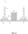
- FIG. 1 is a schematic illustration of a continuous wave radar system having an isolating device in accordance with one embodiment of the present disclosure
- FIG. 2 is a schematic illustration of leakage signal attenuation of the isolating device in the continuous wave radar system in accordance with one embodiment of the present disclosure
- FIG. 3 is a schematic illustration of an arrangement of the metal plates of the isolating device of the continuous wave radar system in accordance with one embodiment of the present disclosure
- FIG. 4 is a schematic illustration of another arrangement of the metal plates of the isolating device of the continuous wave radar system in accordance with one embodiment of the present disclosure
- FIG. 5 is a schematic illustration of a spacing between the metal plates and a distance between the transmitter and the receiver of the continuous wave radar system in accordance with one embodiment of the present disclosure
- FIG. 6 is a schematic illustration of a top view of the continuous wave radar system in accordance with one embodiment of the present disclosure
- FIG. 7 is a schematic illustration of a configuration of the metal plates of the isolating device of the continuous wave radar system in accordance with one embodiment of the present disclosure
- FIG. 8 is a schematic illustration of another configuration of the metal plates of the isolating device of the continuous wave radar system in accordance with one embodiment of the present disclosure
- FIG. 9 is a schematic illustration of yet another configuration of the metal plates of the isolating device of the continuous wave radar system in accordance with one embodiment of the present disclosure.
- FIG. 10 is a schematic illustration of the other configuration of the metal plates of the isolating device of the continuous wave radar system in accordance with one embodiment of the present disclosure
- FIG. 11 is a schematic illustration of still another configuration of the metal plates of the isolating device of the continuous wave radar system in accordance with one embodiment of the present disclosure
- FIG. 12 is a schematic illustration of a configuration of a wave absorbing material for the isolating device of the continuous wave radar system in accordance with one embodiment of the present disclosure
- FIG. 13 is a schematic illustration of another configuration of the wave absorbing material for the isolating device of the continuous wave radar system in accordance with one embodiment of the present disclosure
- FIG. 14 is a schematic illustration of yet another configuration of the wave absorbing material for the isolating device of the continuous wave radar system in accordance with one embodiment of the present disclosure
- FIG. 15 is a schematic illustration of various means of connection between the metal plates and a substrate of the continuous wave radar system in accordance with one embodiment of the present disclosure
- FIG. 16 is a graphical view of isolation between the transmitter and the receiver before grounding the metal plates in accordance with one embodiment of the present disclosure.
- FIG. 17 is a graphical view of isolation between the transmitter and the receiver after grounding the metal plates in accordance with one embodiment of the present disclosure.
- a continuous wave radar system 1 includes a substrate 11 , a transmitter 12 disposed over the substrate 11 , a receiver 13 disposed over the substrate 11 , and an isolating device 14 disposed over the substrate and arranged between the transmitter 12 and the receiver 13 .
- the isolating device 14 includes a plurality of metal plates 141 and is configured to attenuate leakage signal transmitted from the transmitter 12 to the receiver 13 by the metal plates 141 .
- the metal plates 141 are arranged parallelly to and spaced apart from each other.
- the metal plates 141 are grounded via electrical connection between the metal plates 141 and the substrate 11 ; the transmitter 12 and the receiver 13 are grounded as well.
- the transmitter 12 , the receiver 13 , and the isolating device 14 are electrically connected to a common ground via the substrate.
- leakage signals pass through the metal plates 141 of the isolating device 14 from the transmitter 12 to the receiver 13 , an eddy current is induced in each of the metal plates 141 and directed away by grounding, therefore attenuating the leakage signals received by the receiver 13 .
- the transmitter 12 and/or the receiver 13 include a directional antenna having an antenna pattern P.
- the directional antennas may transmit or receive electromagnetic waves in a predefined direction, which may be substantially perpendicular to the substrate 11 .
- FIG. 2 illustrates the attenuation of an exemplary leakage signal from the transmitter 12 to the receiver 13 by the isolating device 14 of the continuous wave radar system 1 .
- the continuous wave radar system 1 includes the substrate 11 , the transmitter 12 disposed on the substrate 11 , the receiver 13 disposed on the substrate 11 , and the isolating device 14 disposed on the substrate and between the transmitter 12 and the receiver 13 .
- the isolating device 14 includes metal plates 141 a , 141 b , 141 c , 141 d and 141 e .
- the leakage signal W 1 When the leakage signal W 1 is transmitted from the transmitter 12 to the receiver 13 , the leakage signal W 1 passes through the metal plate 141 a and induces an eddy current i 1 in the metal plate 141 a . Since the metal plate 141 a is grounded, the eddy current i 1 is directed away from the metal plate 141 a toward the ground. Consequently, the leakage signal W 1 is attenuated to the leakage signal W 2 after passing through the metal plate 141 a . Subsequently, the leakage signal W 2 is attenuated to leakage signals W 3 , W 4 , W 5 , W 6 after passing through the metal plate 141 b , 141 c , 141 d , 141 e , respectively.
- the leakage signals W 1 , W 2 , W 3 , W 4 , W 5 are sequentially attenuated to leakage signal W 6 as eddy currents i 2 , i 3 , i 4 , i 5 are respectively induced in the metal plates 141 b , 141 c , 141 d , 141 e and directed away by grounding. Therefore, the magnitude of the eddy current reduces from i 1 to i 5 .
- the metal plates 141 of the isolating device 14 are parallelly arranged and evenly spaced on the substrate 11 .
- the spaces S between each adjacent pair of the metal plates 141 are consistent.
- the evenly distributed spaces S reduce possibility of coupling between eddy currents induced in each adjacent pair of metal plates 141 when the leakage signals pass through.
- the metal plates 141 of the isolating device 14 may be arranged in various configurations; for example, the metal plates 141 may be arranged to lean towards the receiver 13 , as illustrated in FIG. 3 , or lean towards the transmitter 12 , as illustrated in FIG. 4 . In some embodiments, as illustrated in FIG.
- the metal plates 141 may be substantially perpendicular to the substrate 11 , as such arrangement results in minimal interference to the electromagnetic field from the transmitter 12 and to the receiver 13 .
- the isolating device 14 is placed equally apart from the transmitter 12 and the receiver 13 .
- the space S between the metal plates 141 may be 0.25-0.45 fold of a wavelength of a wave transmitted by the transmitter 12
- a distance D between the transmitter 12 and the receiver 13 may be 3-5 folds of the wavelength of the wave transmitted by the transmitter 12 .
- the dimension of the space S and the distance D can be scaled according to the operating frequency of the transmitter 12 .
- the transmitter 12 and the receiver 13 of the continuous wave radar system 1 has a length of L 1
- the metal plates 14 of the continuous wave radar system 1 has a length of L 2 .
- the length L 1 is substantially equal to the length L 2 , such that the metal plates 14 can attenuating the leakage signals from the transmitter 12 towards the receiver 13 .
- the heights of the metal plates 141 may be inconsistent or vary along a direction from the transmitter 12 to the receiver 13 . More specifically, for maintaining the electromagnetic field around the transmitter 12 and the receiver 13 , the metal plate 141 a closest to the transmitter 12 and the metal plate 141 b closest to the receiver 13 may be the shortest among the metal plates 141 in the isolating device 14 .
- the top edges of the metal plates 141 may form a symmetrical mountain-shape M.
- the mountain-shape M can be a profile having a single peak between two slopes.
- FIG. 8 the heights of the metal plates 141 may be inconsistent or vary along a direction from the transmitter 12 to the receiver 13 . More specifically, for maintaining the electromagnetic field around the transmitter 12 and the receiver 13 , the metal plate 141 a closest to the transmitter 12 and the metal plate 141 b closest to the receiver 13 may be the shortest among the metal plates 141 in the isolating device 14 .
- the top edges of the metal plates 141 may form a
- the isolating device 14 may be arranged closer to the transmitter 12 for fulfilling certain application specific requirements. Therefore, a distance K 1 between the isolating device 14 and the transmitter 12 may be shorter than a distance K 2 between the isolating device and the receiver 12 ; such configuration may cause an interference to the electromagnetic field of the transmitter 12 .
- the top edges of the metal plates 141 may be configured to form an asymmetrical mountain-shape M.
- a slope of the mountain-shape M may be formed by a height difference H between each adjacent pair of the metal plates 141 , and the height difference H is preferably 0.1-0.5 fold of a wavelength of a wave transmitted by the transmitter 12 .
- the heights T of the metal plates may fall within a range of 3-6 folds of a wavelength of a wave transmitted by the transmitter 12 .
- the metal plates 141 are preferably taller than the transmitter 12 and the receiver 13 .
- the dimension of the height difference H and the heights can be scaled corresponding to the distance D mentioned in FIG. 5 .
- the top edge of the metal plates 141 of the isolating device 14 of the continuous wave radar system 1 may be round.
- the rounded top edges of the metal plates 141 prevent undesired radiation caused by the induced eddy current in the metal plates 141 , because sharp edges tend to act as small antennas when eddy currents are induced.
- a thickness Q of the metal plates 141 may fall within a range of 1-5 mm and is preferably consistent throughout all of the metal plates 141 to minimize the undesired radiation.
- the metal plates 141 may be made of aluminum to prevent self-bending of the metal plates 141 due to their own weight.
- the isolating device 14 may further include a wave absorbing material 142 disposed within the spaces between the metal plates 141 .
- the wave absorbing material 142 may fully or partially fill the spaces between the metal plates 141 , as exemplified in FIG. 12 and FIG. 13 , respectively.
- the wave absorbing material 142 may be coated on the metal plates 141 of the isolating device 14 .
- the wave absorbing material 142 may be, but is not limited to, graphene, graphite, ferrite, silicon carbide, barium titanate, etc.
- the metal plates 141 may be L-shaped to allow the metal plates 141 to be fixed to the substrate 11 by screws 15 , as shown in an enlarged cross-sectional view V 1 .
- the metal plates 141 may also be fixed to the substrate 11 by wedging into the substrate 11 , as shown in an enlarged cross-sectional view V 2 .
- the substrate 11 can be metallic, such that the metal plates 141 are grounded with the substrates 11 either by screws 15 or by directly wedging into the substrate 11 .
- FIG. 16 and FIG. 17 the results of isolation detected between the transmitter 12 and the receiver 13 before and after grounding the metal plates 14 are shown, respectively. It could be seen that the isolation between the transmitter 12 and the receiver 13 is much lower in FIG. 16 than in FIG. 17 , therefore grounding the metal plates 14 improves attenuation of the leakage signals from the transmitter 12 toward the receiver 13 significantly.
- the continuous wave radar system utilize the isolating device having a plurality of grounded metal plates to attenuate leakage signals transmitted from the transmitter to the receiver. Therefore, the isolating device improves the isolation between the transmitter and the receiver without significantly increasing the size, weight or circuit complexity of the continuous wave radar system.
Landscapes
- Engineering & Computer Science (AREA)
- Radar, Positioning & Navigation (AREA)
- Remote Sensing (AREA)
- Computer Networks & Wireless Communication (AREA)
- Physics & Mathematics (AREA)
- General Physics & Mathematics (AREA)
- Radar Systems Or Details Thereof (AREA)
Abstract
Description
Claims (19)
Priority Applications (2)
| Application Number | Priority Date | Filing Date | Title |
|---|---|---|---|
| US16/695,118 US11372080B2 (en) | 2019-11-25 | 2019-11-25 | Continuous wave radar system |
| TW108145577A TWI731510B (en) | 2019-11-25 | 2019-12-12 | Continuous wave radar system |
Applications Claiming Priority (1)
| Application Number | Priority Date | Filing Date | Title |
|---|---|---|---|
| US16/695,118 US11372080B2 (en) | 2019-11-25 | 2019-11-25 | Continuous wave radar system |
Publications (2)
| Publication Number | Publication Date |
|---|---|
| US20210156956A1 US20210156956A1 (en) | 2021-05-27 |
| US11372080B2 true US11372080B2 (en) | 2022-06-28 |
Family
ID=75975302
Family Applications (1)
| Application Number | Title | Priority Date | Filing Date |
|---|---|---|---|
| US16/695,118 Active 2040-11-30 US11372080B2 (en) | 2019-11-25 | 2019-11-25 | Continuous wave radar system |
Country Status (2)
| Country | Link |
|---|---|
| US (1) | US11372080B2 (en) |
| TW (1) | TWI731510B (en) |
Families Citing this family (1)
| Publication number | Priority date | Publication date | Assignee | Title |
|---|---|---|---|---|
| IL282938B2 (en) * | 2021-05-04 | 2023-04-01 | Elbit Systems Ew And Sigint Elisra Ltd | Antenna-based radio detection systems and methods |
Citations (8)
| Publication number | Priority date | Publication date | Assignee | Title |
|---|---|---|---|---|
| US5574464A (en) * | 1995-10-17 | 1996-11-12 | Northrop Grumman Corporation | High-speed switching device for monostatic impulse radar |
| US20020101388A1 (en) | 2000-11-17 | 2002-08-01 | Ems Technologies | Radio frequency isolation card |
| US20070046558A1 (en) | 2005-08-26 | 2007-03-01 | Ems Technologies, Inc. | Method and System for Increasing the Isolation Characteristic of a Crossed Dipole Pair Dual Polarized Antenna |
| CN101872894A (en) | 2010-04-01 | 2010-10-27 | 电子科技大学 | A Reconfigurable Dielectric Resonant Antenna and Its Phased Array |
| CN206506025U (en) | 2016-12-29 | 2017-09-19 | 深圳天珑无线科技有限公司 | The multi-input/output antenna and mobile terminal of restructural |
| US20180203110A1 (en) * | 2017-01-13 | 2018-07-19 | Honda Motor Co., Ltd. | Cover member of sensor configured to detect ambient situation of vehicle and sensor assembly |
| WO2019050284A1 (en) | 2017-09-06 | 2019-03-14 | 삼성전자주식회사 | Antenna device having isolation structure between antenna elements |
| US20200412012A1 (en) * | 2019-06-26 | 2020-12-31 | Honeywell International Inc. | Fixing structure to enhance the mechanical reliability of plate slot array antenna based on siw technology |
-
2019
- 2019-11-25 US US16/695,118 patent/US11372080B2/en active Active
- 2019-12-12 TW TW108145577A patent/TWI731510B/en active
Patent Citations (8)
| Publication number | Priority date | Publication date | Assignee | Title |
|---|---|---|---|---|
| US5574464A (en) * | 1995-10-17 | 1996-11-12 | Northrop Grumman Corporation | High-speed switching device for monostatic impulse radar |
| US20020101388A1 (en) | 2000-11-17 | 2002-08-01 | Ems Technologies | Radio frequency isolation card |
| US20070046558A1 (en) | 2005-08-26 | 2007-03-01 | Ems Technologies, Inc. | Method and System for Increasing the Isolation Characteristic of a Crossed Dipole Pair Dual Polarized Antenna |
| CN101872894A (en) | 2010-04-01 | 2010-10-27 | 电子科技大学 | A Reconfigurable Dielectric Resonant Antenna and Its Phased Array |
| CN206506025U (en) | 2016-12-29 | 2017-09-19 | 深圳天珑无线科技有限公司 | The multi-input/output antenna and mobile terminal of restructural |
| US20180203110A1 (en) * | 2017-01-13 | 2018-07-19 | Honda Motor Co., Ltd. | Cover member of sensor configured to detect ambient situation of vehicle and sensor assembly |
| WO2019050284A1 (en) | 2017-09-06 | 2019-03-14 | 삼성전자주식회사 | Antenna device having isolation structure between antenna elements |
| US20200412012A1 (en) * | 2019-06-26 | 2020-12-31 | Honeywell International Inc. | Fixing structure to enhance the mechanical reliability of plate slot array antenna based on siw technology |
Also Published As
| Publication number | Publication date |
|---|---|
| TW202120955A (en) | 2021-06-01 |
| US20210156956A1 (en) | 2021-05-27 |
| TWI731510B (en) | 2021-06-21 |
Similar Documents
| Publication | Publication Date | Title |
|---|---|---|
| US11588246B2 (en) | NFC antenna structure and NFC circuit board and wireless charger using the same | |
| US20160344093A1 (en) | Antenna device, wireless communication apparatus, and radar apparatus | |
| US5861860A (en) | Protector for one or more electromagnetic sensors | |
| US11362430B1 (en) | Tunable antenna isolators | |
| US8681064B2 (en) | Resistive frequency selective surface circuit for reducing coupling and electromagnetic interference in radar antenna arrays | |
| JP6938217B2 (en) | Antenna device and radar device | |
| CN113131221B (en) | An X-Band Energy Selective Surface | |
| US20150145741A1 (en) | Wideband Simultaneous Transmit And Receive (STAR) Antenna With Miniaturized TEM Horn Elements | |
| US20180212328A1 (en) | Wireless device | |
| CN102509883A (en) | Antenna structure capable of suppressing interference between antennae | |
| US11372080B2 (en) | Continuous wave radar system | |
| Güneş et al. | GSM filtering of horn antennas using modified double square frequency selective surface | |
| US12451603B2 (en) | Multiband loop antenna | |
| TWI626793B (en) | Anti-electromagnetic interfernce unit | |
| US20110080330A1 (en) | Multiband antenna system with shield | |
| US9929455B2 (en) | Electronic circuit | |
| TWI533506B (en) | Communication device and wideband decoupled dual-antenna element therein | |
| US20090160729A1 (en) | Antenna array with reduced electromagnetic coupling | |
| JP6516185B2 (en) | Radar equipment | |
| CN108321549A (en) | Microwave absorbing structure | |
| US10111318B2 (en) | Circuit substrate, and noise reduction method for circuit substrate | |
| TWI881472B (en) | Antenna structure and electronic device | |
| US9231308B2 (en) | Feeding apparatus and low noise block down-converter | |
| KR101809531B1 (en) | Cylindrical Electromagnetic BandGap And Coaxial Cable Having it | |
| JP4803173B2 (en) | Circuit board |
Legal Events
| Date | Code | Title | Description |
|---|---|---|---|
| AS | Assignment |
Owner name: NATIONAL CHUNG-SHAN INSTITUTE OF SCIENCE AND TECHNOLOGY, TAIWAN Free format text: ASSIGNMENT OF ASSIGNORS INTEREST;ASSIGNORS:TSAI, SHIH-CHE;CHEN, JER-LONG;LIN, MIN-CHING;AND OTHERS;SIGNING DATES FROM 20191118 TO 20191125;REEL/FRAME:051111/0180 |
|
| FEPP | Fee payment procedure |
Free format text: ENTITY STATUS SET TO UNDISCOUNTED (ORIGINAL EVENT CODE: BIG.); ENTITY STATUS OF PATENT OWNER: LARGE ENTITY |
|
| STPP | Information on status: patent application and granting procedure in general |
Free format text: DOCKETED NEW CASE - READY FOR EXAMINATION |
|
| STPP | Information on status: patent application and granting procedure in general |
Free format text: NON FINAL ACTION MAILED |
|
| STPP | Information on status: patent application and granting procedure in general |
Free format text: RESPONSE TO NON-FINAL OFFICE ACTION ENTERED AND FORWARDED TO EXAMINER |
|
| STPP | Information on status: patent application and granting procedure in general |
Free format text: NOTICE OF ALLOWANCE MAILED -- APPLICATION RECEIVED IN OFFICE OF PUBLICATIONS |
|
| STPP | Information on status: patent application and granting procedure in general |
Free format text: PUBLICATIONS -- ISSUE FEE PAYMENT VERIFIED |
|
| STCF | Information on status: patent grant |
Free format text: PATENTED CASE |
|
| MAFP | Maintenance fee payment |
Free format text: PAYMENT OF MAINTENANCE FEE, 4TH YEAR, LARGE ENTITY (ORIGINAL EVENT CODE: M1551); ENTITY STATUS OF PATENT OWNER: LARGE ENTITY Year of fee payment: 4 |