US11371663B2 - Light bulb shaped light emitting diode module - Google Patents
Light bulb shaped light emitting diode module Download PDFInfo
- Publication number
- US11371663B2 US11371663B2 US16/792,784 US202016792784A US11371663B2 US 11371663 B2 US11371663 B2 US 11371663B2 US 202016792784 A US202016792784 A US 202016792784A US 11371663 B2 US11371663 B2 US 11371663B2
- Authority
- US
- United States
- Prior art keywords
- emitting diode
- light emitting
- diode module
- base
- bulb
- Prior art date
- Legal status (The legal status is an assumption and is not a legal conclusion. Google has not performed a legal analysis and makes no representation as to the accuracy of the status listed.)
- Active, expires
Links
Images


Classifications
-
- F—MECHANICAL ENGINEERING; LIGHTING; HEATING; WEAPONS; BLASTING
- F21—LIGHTING
- F21K—NON-ELECTRIC LIGHT SOURCES USING LUMINESCENCE; LIGHT SOURCES USING ELECTROCHEMILUMINESCENCE; LIGHT SOURCES USING CHARGES OF COMBUSTIBLE MATERIAL; LIGHT SOURCES USING SEMICONDUCTOR DEVICES AS LIGHT-GENERATING ELEMENTS; LIGHT SOURCES NOT OTHERWISE PROVIDED FOR
- F21K9/00—Light sources using semiconductor devices as light-generating elements, e.g. using light-emitting diodes [LED] or lasers
- F21K9/20—Light sources comprising attachment means
- F21K9/23—Retrofit light sources for lighting devices with a single fitting for each light source, e.g. for substitution of incandescent lamps with bayonet or threaded fittings
- F21K9/235—Details of bases or caps, i.e. the parts that connect the light source to a fitting; Arrangement of components within bases or caps
-
- F—MECHANICAL ENGINEERING; LIGHTING; HEATING; WEAPONS; BLASTING
- F21—LIGHTING
- F21V—FUNCTIONAL FEATURES OR DETAILS OF LIGHTING DEVICES OR SYSTEMS THEREOF; STRUCTURAL COMBINATIONS OF LIGHTING DEVICES WITH OTHER ARTICLES, NOT OTHERWISE PROVIDED FOR
- F21V19/00—Fastening of light sources or lamp holders
- F21V19/001—Fastening of light sources or lamp holders the light sources being semiconductors devices, e.g. LEDs
- F21V19/003—Fastening of light source holders, e.g. of circuit boards or substrates holding light sources
-
- F—MECHANICAL ENGINEERING; LIGHTING; HEATING; WEAPONS; BLASTING
- F21—LIGHTING
- F21V—FUNCTIONAL FEATURES OR DETAILS OF LIGHTING DEVICES OR SYSTEMS THEREOF; STRUCTURAL COMBINATIONS OF LIGHTING DEVICES WITH OTHER ARTICLES, NOT OTHERWISE PROVIDED FOR
- F21V19/00—Fastening of light sources or lamp holders
- F21V19/04—Fastening of light sources or lamp holders with provision for changing light source, e.g. turret
-
- F—MECHANICAL ENGINEERING; LIGHTING; HEATING; WEAPONS; BLASTING
- F21—LIGHTING
- F21V—FUNCTIONAL FEATURES OR DETAILS OF LIGHTING DEVICES OR SYSTEMS THEREOF; STRUCTURAL COMBINATIONS OF LIGHTING DEVICES WITH OTHER ARTICLES, NOT OTHERWISE PROVIDED FOR
- F21V23/00—Arrangement of electric circuit elements in or on lighting devices
- F21V23/003—Arrangement of electric circuit elements in or on lighting devices the elements being electronics drivers or controllers for operating the light source, e.g. for a LED array
-
- F—MECHANICAL ENGINEERING; LIGHTING; HEATING; WEAPONS; BLASTING
- F21—LIGHTING
- F21V—FUNCTIONAL FEATURES OR DETAILS OF LIGHTING DEVICES OR SYSTEMS THEREOF; STRUCTURAL COMBINATIONS OF LIGHTING DEVICES WITH OTHER ARTICLES, NOT OTHERWISE PROVIDED FOR
- F21V23/00—Arrangement of electric circuit elements in or on lighting devices
- F21V23/04—Arrangement of electric circuit elements in or on lighting devices the elements being switches
-
- F—MECHANICAL ENGINEERING; LIGHTING; HEATING; WEAPONS; BLASTING
- F21—LIGHTING
- F21V—FUNCTIONAL FEATURES OR DETAILS OF LIGHTING DEVICES OR SYSTEMS THEREOF; STRUCTURAL COMBINATIONS OF LIGHTING DEVICES WITH OTHER ARTICLES, NOT OTHERWISE PROVIDED FOR
- F21V23/00—Arrangement of electric circuit elements in or on lighting devices
- F21V23/06—Arrangement of electric circuit elements in or on lighting devices the elements being coupling devices, e.g. connectors
-
- H—ELECTRICITY
- H05—ELECTRIC TECHNIQUES NOT OTHERWISE PROVIDED FOR
- H05B—ELECTRIC HEATING; ELECTRIC LIGHT SOURCES NOT OTHERWISE PROVIDED FOR; CIRCUIT ARRANGEMENTS FOR ELECTRIC LIGHT SOURCES, IN GENERAL
- H05B45/00—Circuit arrangements for operating light-emitting diodes [LED]
- H05B45/10—Controlling the intensity of the light
-
- H—ELECTRICITY
- H05—ELECTRIC TECHNIQUES NOT OTHERWISE PROVIDED FOR
- H05B—ELECTRIC HEATING; ELECTRIC LIGHT SOURCES NOT OTHERWISE PROVIDED FOR; CIRCUIT ARRANGEMENTS FOR ELECTRIC LIGHT SOURCES, IN GENERAL
- H05B47/00—Circuit arrangements for operating light sources in general, i.e. where the type of light source is not relevant
- H05B47/10—Controlling the light source
- H05B47/175—Controlling the light source by remote control
- H05B47/19—Controlling the light source by remote control via wireless transmission
-
- F—MECHANICAL ENGINEERING; LIGHTING; HEATING; WEAPONS; BLASTING
- F21—LIGHTING
- F21V—FUNCTIONAL FEATURES OR DETAILS OF LIGHTING DEVICES OR SYSTEMS THEREOF; STRUCTURAL COMBINATIONS OF LIGHTING DEVICES WITH OTHER ARTICLES, NOT OTHERWISE PROVIDED FOR
- F21V19/00—Fastening of light sources or lamp holders
- F21V19/001—Fastening of light sources or lamp holders the light sources being semiconductors devices, e.g. LEDs
- F21V19/003—Fastening of light source holders, e.g. of circuit boards or substrates holding light sources
- F21V19/004—Fastening of light source holders, e.g. of circuit boards or substrates holding light sources by deformation of parts or snap action mountings, e.g. using clips
-
- F—MECHANICAL ENGINEERING; LIGHTING; HEATING; WEAPONS; BLASTING
- F21—LIGHTING
- F21Y—INDEXING SCHEME ASSOCIATED WITH SUBCLASSES F21K, F21L, F21S and F21V, RELATING TO THE FORM OR THE KIND OF THE LIGHT SOURCES OR OF THE COLOUR OF THE LIGHT EMITTED
- F21Y2115/00—Light-generating elements of semiconductor light sources
- F21Y2115/10—Light-emitting diodes [LED]
-
- H—ELECTRICITY
- H05—ELECTRIC TECHNIQUES NOT OTHERWISE PROVIDED FOR
- H05B—ELECTRIC HEATING; ELECTRIC LIGHT SOURCES NOT OTHERWISE PROVIDED FOR; CIRCUIT ARRANGEMENTS FOR ELECTRIC LIGHT SOURCES, IN GENERAL
- H05B45/00—Circuit arrangements for operating light-emitting diodes [LED]
- H05B45/20—Controlling the colour of the light
Definitions
- Embodiments of the technology relate generally to a light emitting diode module in the shape of a light bulb.
- LED light emitting diode
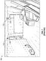
- FIG. 1 illustrates an example of a typical construction site 100 that is lit using conventional incandescent light bulbs 105 .
- incandescent bulbs 105 are often inserted into conventional Edison base lighting sockets, such as an E26 socket, and the sockets are attached to electrical wiring 110 that hangs down into the construction site.
- the temporary lighting will typically be replaced by lighting fixtures, such as a surface mounted or recessed lighting fixture.
- LED light sources in general has included adoption of LED light sources as a temporary light source during construction.
- energy efficient light sources such as LED light sources
- the conventional lighting socket such as an Edison base socket
- the supporting trim are removed and discarded and replaced with an integral LED retrofit module.
- LED light source based fixtures are installed which have an electrical connector typically used with an LED light source, such as the CJT type of connector 212 shown extending from the can 202 of the recessed light fixture housing 200 in FIG. 2 .
- FIG. 3 illustrates an example of a construction site 300 with CJT connectors 312 hanging from recessed housings 302 installed in a ceiling.
- Conventional LED light modules 315 are attached to the CJT connectors 312 and hang down from the recessed housing 302 for temporary lighting during construction.
- the conventional LED light modules 315 are heavier, more complex, and more expensive than a conventional incandescent bulb.
- the conventional LED light modules 315 shown in FIG. 3 include an LED light source and a trim, and in some cases can include other components such as a lens.
- Arranging the LED light modules 315 to hang down from the recessed housings 302 for temporary lighting during construction as shown in FIG. 3 presents problems because of the greater weight, complexity and expense of the LED light modules 315 . For example, in the hanging position shown in FIG.
- the LED light modules 315 are exposed and have a greater likelihood of being damaged when they hang down from the ceiling outside of the recessed housing 302 as shown in FIG. 3 . Additionally, the CJT connector 312 may not provide sufficient support for the weight of the LED light module 315 .
- the present disclosure is directed to a light bulb shaped light emitting diode module.
- the light emitting diode module comprises a bulb, a body attached to the bulb, and a base attached to the body.
- the body comprises a light emitting diode and the base comprises a receptacle configured to receive an electrical connector.
- the body can further comprise a driver or power supply that controls the delivery of power to the light emitting diode.
- One or more tabs can extend from the base and can secure the electrical connector to the module when the electrical connector is attached to the receptacle.
- the base can also include a sidewall that is flexible and that can be extended or contracted to meet the dimensions or needs of a luminaire.
- FIG. 1 is an image of a construction site with temporary lighting using incandescent bulbs in accordance with the prior art.
- FIG. 2 is an image of a recessed luminaire housing as is known in the prior art.
- FIG. 3 is an image of a construction site with temporary lighting using LED modules in accordance with the prior art.
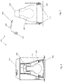
- FIGS. 4A, 4B, and 4C are perspective, side and top views, respectively, of an LED module in accordance with an example embodiment of the present disclosure.
- FIGS. 5A, 5B, and 5C are perspective, side and top views, respectively, of an LED module in accordance with another example embodiment of the present disclosure.
- FIGS. 6 and 7 illustrate retrofitting a conventional luminaire with an LED module in accordance with the example embodiments of the present disclosure.
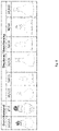
- FIG. 8 illustrates examples of ANSI light bulb types.
- the example embodiments discussed herein are directed to a light emitting diode module (“LED module”).
- the LED module can have a shape corresponding to an ANSI light bulb type so that the LED module can be used more easily in both LED luminaries and to retrofit luminaries with conventional light bulbs.
- Benefits associated with the LED module described herein can include, but are not limited to, simpler installation and adjustment of an LED module, greater ease of use as temporary lighting for construction sites, and the capability to meet one or more air tight standards. While the example embodiments described herein relate to recessed luminaries, the example embodiments can be applied to a variety of indoor and outdoor lighting systems, including in homes, offices, schools, garages, stadiums, warehouses, and a variety of other buildings and environments.
- the LED module 400 comprises a bulb 405 , a body 410 , and a base 415 .
- the bulb 405 has a shape corresponding to an ANSI light bulb type, in this case an A15 or A19 bulb.
- the bulb can be made from a translucent material, such as glass or a plastic, and comprises a head 406 and a neck 407 .
- the neck 407 of the bulb 405 attaches to a body 410 and the neck 407 and body 410 can have generally cylindrical shapes.
- the body 410 can contain one or more LED light sources and a driver (or more generally a power supply) for controlling the current supplied to the one or more LED light sources.
- the LEDs or the driver can be located in the neck 407 or can be located in both the body 410 and the neck 407 .
- the one or more LEDs can be oriented to emit light toward the head 406 of the bulb 405 .
- other components such as a wireless transceiver or a processor can be located in the body 410 and/or the neck 407 .
- the driver or power supply can comprise one or more components generally known to those of skill in this field for providing a regulated power to a light emitting diode.
- the power supply can comprise a transformer, an AC to DC converter, or a switched mode power supply.
- the power supply can be located external to the LED module.
- the body 410 of the LED module 400 is attached to the base 415 .
- the base 415 comprises a seat 417 that is attached to a sidewall 418 .
- the sidewall 418 can comprise a flexible construction, such as a construction similar to a bellows or an accordion shape, and can comprise a flexible material such as rubber or thermoplastic.
- the flexible construction of the sidewall 418 allows a telescoping motion whereby the bulb 405 can be adjusted to be closer or farther from the seat 417 .
- the adjustability of the sidewall 418 is useful in positioning the LED module 400 within luminaries and trims of varying shape and size so that the bulb is centered or positioned as desired.
- the sidewall 418 is made of a compressible material, such as rubber, and can also serve as a gasket for creating an air tight seal between the LED module 400 and the luminaire trim or housing in which it is inserted.
- a recessed luminaire it can be desirable for a recessed luminaire to satisfy one or more air tight standards specifying the amount of air that is able to pass through the luminaire, for example, for energy efficiency purposes related to heating and cooling.
- the seat 417 comprises one or more tabs 422 extending from the seat 417 in a direction opposite to the direction of the bulb 405 .
- the tabs 422 provide a mechanical means for fastening the LED module 400 to connector 412 .
- the tabs 422 can have a flange at one end for mechanically attaching to the connector 412 .
- two tabs 422 are illustrated in FIG. 4 , alternate embodiments can have one tab or more than one tab. Additionally, in alternate embodiments, the one or more tabs 422 can be eliminated or can be replaced with other mechanical fasteners.
- the seat 417 also comprises a receptacle 424 configured to receive an electrical connector 412 , such as the CJT type of connector illustrated in FIG. 4 .
- the receptacle 424 is a recess in the seat 417 in which are located electrical contacts for delivering power from the electrical connector 412 to the driver and/or other components within the LED module 400 .
- the electrical connector 412 can provide AC line voltage to the LED module 400 and a power supply or driver within the LED module can convert the AC line voltage to DC power for use by the one or more LEDs.
- the tabs 422 can fit along the sides of the electrical connector 412 so that flanges on the end of the tabs 422 wrap around the back side of the electrical connector 412 and secure the electrical connector to the LED module.
- the positions of the receptacle 424 and the tabs 422 on the seat 417 facilitate a simple installation of the LED module into a luminaire and secure the LED module within the luminaire.
- the receptacle 424 and the tabs 422 can have a variety of shapes, forms, and positions to accommodate other types of electrical connectors.
- the seat 417 comprises a selector switch 420 that permits control of a parameter associated with the LED module 400 .
- the selector switch could have connections to different LEDs located within the LED module 400 , thereby permitting adjustment of a correlated color temperature or of the lumens emitted from the LED module 400 .
- the LED module 400 can comprise a transceiver for wireless communication with a remote controller and the selector switch 420 can permit selection among different radio frequency communication protocols so that the LED module 400 is capable of communicating with different controllers.
- the position of the selector switch 420 allows a user to set one of the parameters when initially installing the LED module 400 and the parameter can easily be adjusted at a later point by removing the LED module 400 and adjusting the selector switch 420 .
- selector switch 420 can take a variety of forms, including but not limited to, a DIP switch, a rocker switch, a rotary switch, a push button switch, and a slider switch. In alternate embodiments, the selector switch can be located at other positions such as on the sidewall 418 , on the body 410 , or on the neck 407 .
- FIGS. 5A, 5B, and 5C images of another example embodiment of an LED module in accordance with the present disclosure is shown.
- Most of the components shown in example LED module 500 are similar to the components previously described in connection with example LED module 400 and analogous components are indicated by the same last two reference number digits. It should be assumed that the analogous components illustrated in FIG. 5 operate in a similar manner to the corresponding components of FIG. 4 and a detailed description will not be repeated.
- LED module 500 comprises a bulb 505 having a head 506 and a neck 507 .
- the neck 507 of the bulb 505 attaches to a body 510 , which in turn attaches to a base 515 .
- One or more LEDs and other electrical components, such as a power supply, can be located within the body 510 or the base 515 .
- the base 515 comprises a sidewall 518 and a seat 517 .
- the sidewall 518 can have a flexible construction that permits extension or retraction of the LED module within a luminaire.
- the seat 517 comprises a receptacle 524 for receiving an electrical connector 512 .
- One or more tabs 522 can extend from the seat 517 in a direction opposite to the bulb 505 and the one or more tabs 522 can be configured to secure the electrical connector 512 in the receptacle 524 .
- the tabs 522 can comprise flanges at the ends of the tab farthest from the bulb 505 and the flanges can wrap around and secure the electrical connector 512 in the receptacle 524 .
- the LED module 500 can also comprise a selector switch 520 which can be used to control power deliver to different LEDs within the LED module 500 , thereby permitting control of correlated color temperature or light intensity.
- the selector switch 520 can control other functions, such as a radio transmission protocol for a radio transceiver located within the LED module 500 .
- the selector switch 520 is shown located on the seat 517 , in alternate embodiments the selector switch can be located at other positions on the LED module 500 .
- LED module 500 is different from the previous example in that the shape of the bulb corresponds to the directional or beam forming ANSI bulb types such as type PAR 30 .
- the head 506 of the bulb 505 has a different shape in that it comprises a substantially flat front face and a substantially conical sidewall.
- the interior of the substantially conical sidewall can include a reflective coating that receives a portion of the light emitted by the one or more LEDs within the LED module 500 and redirects that portion of the light toward the substantially flat front face for emission from the LED module 500 .
- the bulb shapes shown in FIGS. 4 and 5 are examples and in other embodiments of the LED module, the bulb can have other shapes.
- the bulb of the LED module can correspond with any of the standard ANSI shapes shown in FIG. 8 .
- FIGS. 6 and 7 illustrate use of the example LED module in a retrofit application.
- a conventional luminaire 600 is illustrated comprising a housing can 602 , a trim 604 , and a conventional Edison base socket 630 .
- two different conventional Edison base bulbs 632 and 634 are shown superimposed on each other in FIG. 6 . It should be understood that in practice, two bulbs would not be positioned in the same Edison base socket simultaneously.
- the housing can 602 has been eliminated in order to simplify the illustration and torsion springs 612 are visible on either side of the trim 604 .
- FIG. 7 also shows the Edison base socket 630 and the Edison base bulb 632 in dotted lines for illustrative purposes.
- the Edison base bulb 632 can be removed and adapter 640 can be installed. That is, the Edison screw connector 642 of adapter 640 can be installed in the existing Edison base socket 630 .
- the opposite end of the adapter 640 has a connector 644 , such as the CJT type connector described previously.
- An LED module of the present disclosure such as LED module 400 or 500 , can be attached so that the connector 644 is inserted into the receptacle in the base of the LED module and then the LED module can be positioned within the trim 604 . If the height of the LED module within the trim 604 requires adjustment, the previously described flexible sidewall of the base of the LED module can be extended or compressed to adjust the position of the LED module.
- one or more of the components may be omitted, added, repeated, and/or substituted. Accordingly, embodiments shown in a particular figure should not be considered limited to the specific arrangements of components shown in such figure. Further, if a component of a figure is described but not expressly shown or labeled in that figure, the label used for a corresponding component in another figure can be inferred to that component. Conversely, if a component in a figure is labeled but not described, the description for such component can be substantially the same as the description for the corresponding component in another figure.
- the example luminaries and light emitting diode modules described herein are subject to meeting certain standards and/or requirements.
- NEC National Electric Code
- NEMA National Electrical Manufacturers Association
- IEC International Electrotechnical Commission
- FCC Federal Communication Commission
- IEEE Institute of Electrical and Electronics Engineers
- UL Underwriters Laboratories
- any luminaire or light emitting diode module components can be made from a single piece (e.g., as from a mold, injection mold, die cast, 3-D printing process, extrusion process, stamping process, or other prototype methods).
- a luminaire or light emitting diode module (or components thereof) can be made from multiple pieces that are mechanically coupled to each other.
- the multiple pieces can be mechanically coupled to each other using one or more of a number of coupling methods, including but not limited to epoxy, welding, fastening devices, compression fittings, mating threads, and slotted fittings.
- One or more pieces that are mechanically coupled to each other can be coupled to each other in one or more of a number of ways, including but not limited to fixedly, hingedly, removeably, slidably, and threadably.
- a fastener or attachment feature (including a complementary attachment feature) as described herein can allow one or more components and/or portions of an example luminaire to become coupled, directly or indirectly, to another portion or other component of a luminaire.
- An attachment feature can include, but is not limited to, a flange, a snap, Velcro, a clamp, a portion of a hinge, an aperture, a recessed area, a protrusion, a slot, a spring clip, a tab, a detent, and mating threads.
- a component can be coupled to a luminaire by the direct use of one or more attachment features.
- a portion of a luminaire can be coupled using one or more independent devices that interact with one or more attachment features disposed on the light fixture or a component of the light fixture.
- independent devices can include, but are not limited to, a pin, a hinge, a fastening device (e.g., a bolt, a screw, a rivet), epoxy, glue, adhesive, tape, and a spring.
- One attachment feature described herein can be the same as, or different than, one or more other attachment features described herein.
- a complementary attachment feature also sometimes called a corresponding attachment feature
- a complementary attachment feature as described herein can be a coupling feature that mechanically couples, directly or indirectly, with another coupling feature.
Landscapes
- Engineering & Computer Science (AREA)
- General Engineering & Computer Science (AREA)
- Microelectronics & Electronic Packaging (AREA)
- Physics & Mathematics (AREA)
- Optics & Photonics (AREA)
- Computer Networks & Wireless Communication (AREA)
- Non-Portable Lighting Devices Or Systems Thereof (AREA)
Abstract
Description
Claims (19)
Priority Applications (1)
| Application Number | Priority Date | Filing Date | Title |
|---|---|---|---|
| US16/792,784 US11371663B2 (en) | 2019-02-18 | 2020-02-17 | Light bulb shaped light emitting diode module |
Applications Claiming Priority (2)
| Application Number | Priority Date | Filing Date | Title |
|---|---|---|---|
| US201962807178P | 2019-02-18 | 2019-02-18 | |
| US16/792,784 US11371663B2 (en) | 2019-02-18 | 2020-02-17 | Light bulb shaped light emitting diode module |
Publications (2)
| Publication Number | Publication Date |
|---|---|
| US20200263838A1 US20200263838A1 (en) | 2020-08-20 |
| US11371663B2 true US11371663B2 (en) | 2022-06-28 |
Family
ID=72043129
Family Applications (1)
| Application Number | Title | Priority Date | Filing Date |
|---|---|---|---|
| US16/792,784 Active 2040-02-18 US11371663B2 (en) | 2019-02-18 | 2020-02-17 | Light bulb shaped light emitting diode module |
Country Status (1)
| Country | Link |
|---|---|
| US (1) | US11371663B2 (en) |
Cited By (1)
| Publication number | Priority date | Publication date | Assignee | Title |
|---|---|---|---|---|
| US12504130B1 (en) * | 2024-06-24 | 2025-12-23 | Leedarson Lighting Co., Ltd. | Lighting apparatus with switch rotating ring at bottom of edison cap |
Families Citing this family (7)
| Publication number | Priority date | Publication date | Assignee | Title |
|---|---|---|---|---|
| WO2021174161A1 (en) * | 2020-02-27 | 2021-09-02 | Susan Kelly | Snap-install light assembly and method of use |
| US11473735B2 (en) * | 2020-08-04 | 2022-10-18 | Xiamen Leedarson Lighting Co., Ltd | Light bulb apparatus |
| ES3061352T3 (en) | 2020-10-15 | 2026-04-01 | Signify Holding Bv | A lighting unit such as a bulb |
| GB2600149A (en) * | 2020-10-23 | 2022-04-27 | Andrew Farmer Joseph | A replaceable LED unit for luminaires and integrated lamp luminaires |
| JP7755468B2 (en) * | 2021-12-01 | 2025-10-16 | コイズミ照明株式会社 | lighting equipment |
| CN114963035B (en) * | 2022-06-29 | 2023-04-07 | 广东凯晟科技发展有限公司 | Replaceable LED lamp cap |
| CN118623264A (en) * | 2024-07-01 | 2024-09-10 | 中山市成源光电科技有限公司 | A filament light source assembly, a filament light string, and a filament bulb |
Citations (16)
| Publication number | Priority date | Publication date | Assignee | Title |
|---|---|---|---|---|
| US5160201A (en) * | 1991-07-22 | 1992-11-03 | Display Products, Incorporated | Rotatable led cluster device |
| US20030214810A1 (en) * | 2002-05-17 | 2003-11-20 | Zhang Long Bao | Light source arrangement |
| US20090045715A1 (en) * | 2007-08-16 | 2009-02-19 | Shantha Totada R | Modular lighting apparatus |
| US7575362B1 (en) * | 2008-04-07 | 2009-08-18 | Fu-Hsien Hsu | Stand structure of an LED Christmas lamp |
| US20110095687A1 (en) * | 2009-10-25 | 2011-04-28 | Greenwave Reality, Inc. | Modular Networked Light Bulb |
| US20110163683A1 (en) * | 2011-02-22 | 2011-07-07 | Quarkstar, Llc | Solid State Lamp Using Light Emitting Strips |
| US20120127692A1 (en) * | 2010-11-22 | 2012-05-24 | Tseng-Lu Chien | Lamp holder has built-in night light |
| US20130271981A1 (en) * | 2012-04-13 | 2013-10-17 | Cree, Inc. | Led lamp |
| US20140049963A1 (en) * | 2011-04-26 | 2014-02-20 | The Procter & Gamble Company | Light bulb with loop illumination element |
| US8947013B2 (en) | 2011-12-16 | 2015-02-03 | Marvell World Trade Ltd. | LED-based lamp with user-selectable color temperature |
| US9144129B2 (en) | 2012-06-06 | 2015-09-22 | The Regents Of The University Of California | Switchable luminance LED light bulb |
| US20160245462A1 (en) * | 2015-02-25 | 2016-08-25 | Cree, Inc. | Led lamp |
| US9784417B1 (en) * | 2014-07-21 | 2017-10-10 | Astro, Inc. | Multi-purpose lightbulb |
| US9801250B1 (en) * | 2016-09-23 | 2017-10-24 | Feit Electric Company, Inc. | Light emitting diode (LED) lighting device or lamp with configurable light qualities |
| US20180288847A1 (en) * | 2016-09-23 | 2018-10-04 | Feit Electric Company, Inc. | Light emitting diode (led) lighting device or lamp with configurable light qualities |
| US20190230324A1 (en) * | 2008-11-12 | 2019-07-25 | Tseng-Lu Chien | LED And/Or Laser Projection Light Device |
-
2020
- 2020-02-17 US US16/792,784 patent/US11371663B2/en active Active
Patent Citations (16)
| Publication number | Priority date | Publication date | Assignee | Title |
|---|---|---|---|---|
| US5160201A (en) * | 1991-07-22 | 1992-11-03 | Display Products, Incorporated | Rotatable led cluster device |
| US20030214810A1 (en) * | 2002-05-17 | 2003-11-20 | Zhang Long Bao | Light source arrangement |
| US20090045715A1 (en) * | 2007-08-16 | 2009-02-19 | Shantha Totada R | Modular lighting apparatus |
| US7575362B1 (en) * | 2008-04-07 | 2009-08-18 | Fu-Hsien Hsu | Stand structure of an LED Christmas lamp |
| US20190230324A1 (en) * | 2008-11-12 | 2019-07-25 | Tseng-Lu Chien | LED And/Or Laser Projection Light Device |
| US20110095687A1 (en) * | 2009-10-25 | 2011-04-28 | Greenwave Reality, Inc. | Modular Networked Light Bulb |
| US20120127692A1 (en) * | 2010-11-22 | 2012-05-24 | Tseng-Lu Chien | Lamp holder has built-in night light |
| US20110163683A1 (en) * | 2011-02-22 | 2011-07-07 | Quarkstar, Llc | Solid State Lamp Using Light Emitting Strips |
| US20140049963A1 (en) * | 2011-04-26 | 2014-02-20 | The Procter & Gamble Company | Light bulb with loop illumination element |
| US8947013B2 (en) | 2011-12-16 | 2015-02-03 | Marvell World Trade Ltd. | LED-based lamp with user-selectable color temperature |
| US20130271981A1 (en) * | 2012-04-13 | 2013-10-17 | Cree, Inc. | Led lamp |
| US9144129B2 (en) | 2012-06-06 | 2015-09-22 | The Regents Of The University Of California | Switchable luminance LED light bulb |
| US9784417B1 (en) * | 2014-07-21 | 2017-10-10 | Astro, Inc. | Multi-purpose lightbulb |
| US20160245462A1 (en) * | 2015-02-25 | 2016-08-25 | Cree, Inc. | Led lamp |
| US9801250B1 (en) * | 2016-09-23 | 2017-10-24 | Feit Electric Company, Inc. | Light emitting diode (LED) lighting device or lamp with configurable light qualities |
| US20180288847A1 (en) * | 2016-09-23 | 2018-10-04 | Feit Electric Company, Inc. | Light emitting diode (led) lighting device or lamp with configurable light qualities |
Cited By (1)
| Publication number | Priority date | Publication date | Assignee | Title |
|---|---|---|---|---|
| US12504130B1 (en) * | 2024-06-24 | 2025-12-23 | Leedarson Lighting Co., Ltd. | Lighting apparatus with switch rotating ring at bottom of edison cap |
Also Published As
| Publication number | Publication date |
|---|---|
| US20200263838A1 (en) | 2020-08-20 |
Similar Documents
| Publication | Publication Date | Title |
|---|---|---|
| US11371663B2 (en) | Light bulb shaped light emitting diode module | |
| US11859796B2 (en) | Light emitting diode recessed light fixture | |
| CA2978313C (en) | Control modules having integral antenna components for luminaires and wireless intelligent lighting systems containing the same | |
| US10527264B2 (en) | LED module with mounting brackets | |
| US11920766B2 (en) | Adjustable recessed light fixture | |
| US10436976B2 (en) | Ribs for sealing and aligning an outdoor lightguide luminaire | |
| US10962206B2 (en) | Internet of things adaptable downlight | |
| US9500320B1 (en) | Electrical connector adapters for light fixtures | |
| US20190128508A1 (en) | Under Cabinet Light Fixtures | |
| CN222760751U (en) | A lamp that can be installed by DIY | |
| US12429194B2 (en) | Suspension grid frame lighting apparatus with flexible bracket | |
| US11466825B2 (en) | Recessed luminaire without an integrated light source |
Legal Events
| Date | Code | Title | Description |
|---|---|---|---|
| FEPP | Fee payment procedure |
Free format text: ENTITY STATUS SET TO UNDISCOUNTED (ORIGINAL EVENT CODE: BIG.); ENTITY STATUS OF PATENT OWNER: LARGE ENTITY |
|
| AS | Assignment |
Owner name: SIGNIFY HOLDING B.V., NETHERLANDS Free format text: ASSIGNMENT OF ASSIGNORS INTEREST;ASSIGNOR:EATON INTELLIGENT POWER LIMITED;REEL/FRAME:052633/0158 Effective date: 20200302 |
|
| AS | Assignment |
Owner name: EATON INTELLIGENT POWER LIMITED, IRELAND Free format text: ASSIGNMENT OF ASSIGNORS INTEREST;ASSIGNOR:PYSHOS, STEVEN WALTER;REEL/FRAME:053081/0464 Effective date: 20200217 |
|
| STPP | Information on status: patent application and granting procedure in general |
Free format text: NON FINAL ACTION MAILED |
|
| STPP | Information on status: patent application and granting procedure in general |
Free format text: RESPONSE TO NON-FINAL OFFICE ACTION ENTERED AND FORWARDED TO EXAMINER |
|
| STPP | Information on status: patent application and granting procedure in general |
Free format text: AWAITING TC RESP., ISSUE FEE NOT PAID |
|
| STPP | Information on status: patent application and granting procedure in general |
Free format text: NOTICE OF ALLOWANCE MAILED -- APPLICATION RECEIVED IN OFFICE OF PUBLICATIONS |
|
| STPP | Information on status: patent application and granting procedure in general |
Free format text: PUBLICATIONS -- ISSUE FEE PAYMENT RECEIVED |
|
| STPP | Information on status: patent application and granting procedure in general |
Free format text: PUBLICATIONS -- ISSUE FEE PAYMENT VERIFIED |
|
| STCF | Information on status: patent grant |
Free format text: PATENTED CASE |
|
| MAFP | Maintenance fee payment |
Free format text: PAYMENT OF MAINTENANCE FEE, 4TH YEAR, LARGE ENTITY (ORIGINAL EVENT CODE: M1551); ENTITY STATUS OF PATENT OWNER: LARGE ENTITY Year of fee payment: 4 |