US11370634B2 - Sheet processing apparatus and image forming system - Google Patents
Sheet processing apparatus and image forming system Download PDFInfo
- Publication number
- US11370634B2 US11370634B2 US17/133,918 US202017133918A US11370634B2 US 11370634 B2 US11370634 B2 US 11370634B2 US 202017133918 A US202017133918 A US 202017133918A US 11370634 B2 US11370634 B2 US 11370634B2
- Authority
- US
- United States
- Prior art keywords
- sheet
- folding
- blade
- guide member
- front edge
- Prior art date
- Legal status (The legal status is an assumption and is not a legal conclusion. Google has not performed a legal analysis and makes no representation as to the accuracy of the status listed.)
- Active
Links
Images


Classifications
-
- B—PERFORMING OPERATIONS; TRANSPORTING
- B65—CONVEYING; PACKING; STORING; HANDLING THIN OR FILAMENTARY MATERIAL
- B65H—HANDLING THIN OR FILAMENTARY MATERIAL, e.g. SHEETS, WEBS, CABLES
- B65H45/00—Folding thin material
- B65H45/12—Folding articles or webs with application of pressure to define or form crease lines
- B65H45/18—Oscillating or reciprocating blade folders
-
- B—PERFORMING OPERATIONS; TRANSPORTING
- B65—CONVEYING; PACKING; STORING; HANDLING THIN OR FILAMENTARY MATERIAL
- B65H—HANDLING THIN OR FILAMENTARY MATERIAL, e.g. SHEETS, WEBS, CABLES
- B65H45/00—Folding thin material
- B65H45/02—Folding limp material without application of pressure to define or form crease lines
- B65H45/04—Folding sheets
-
- B—PERFORMING OPERATIONS; TRANSPORTING
- B41—PRINTING; LINING MACHINES; TYPEWRITERS; STAMPS
- B41J—TYPEWRITERS; SELECTIVE PRINTING MECHANISMS, i.e. MECHANISMS PRINTING OTHERWISE THAN FROM A FORME; CORRECTION OF TYPOGRAPHICAL ERRORS
- B41J13/00—Devices or arrangements of selective printing mechanisms, e.g. ink-jet printers or thermal printers, specially adapted for supporting or handling copy material in short lengths, e.g. sheets
- B41J13/0009—Devices or arrangements of selective printing mechanisms, e.g. ink-jet printers or thermal printers, specially adapted for supporting or handling copy material in short lengths, e.g. sheets control of the transport of the copy material
- B41J13/0036—Devices or arrangements of selective printing mechanisms, e.g. ink-jet printers or thermal printers, specially adapted for supporting or handling copy material in short lengths, e.g. sheets control of the transport of the copy material in the output section of automatic paper handling systems
-
- B—PERFORMING OPERATIONS; TRANSPORTING
- B41—PRINTING; LINING MACHINES; TYPEWRITERS; STAMPS
- B41J—TYPEWRITERS; SELECTIVE PRINTING MECHANISMS, i.e. MECHANISMS PRINTING OTHERWISE THAN FROM A FORME; CORRECTION OF TYPOGRAPHICAL ERRORS
- B41J13/00—Devices or arrangements of selective printing mechanisms, e.g. ink-jet printers or thermal printers, specially adapted for supporting or handling copy material in short lengths, e.g. sheets
- B41J13/02—Rollers
- B41J13/076—Construction of rollers; Bearings therefor
-
- B—PERFORMING OPERATIONS; TRANSPORTING
- B41—PRINTING; LINING MACHINES; TYPEWRITERS; STAMPS
- B41J—TYPEWRITERS; SELECTIVE PRINTING MECHANISMS, i.e. MECHANISMS PRINTING OTHERWISE THAN FROM A FORME; CORRECTION OF TYPOGRAPHICAL ERRORS
- B41J13/00—Devices or arrangements of selective printing mechanisms, e.g. ink-jet printers or thermal printers, specially adapted for supporting or handling copy material in short lengths, e.g. sheets
- B41J13/10—Sheet holders, retainers, movable guides, or stationary guides
- B41J13/103—Sheet holders, retainers, movable guides, or stationary guides for the sheet feeding section
-
- B—PERFORMING OPERATIONS; TRANSPORTING
- B42—BOOKBINDING; ALBUMS; FILES; SPECIAL PRINTED MATTER
- B42B—PERMANENTLY ATTACHING TOGETHER SHEETS, QUIRES OR SIGNATURES OR PERMANENTLY ATTACHING OBJECTS THERETO
- B42B4/00—Permanently attaching together sheets, quires or signatures by discontinuous stitching with filamentary material, e.g. wire
-
- B—PERFORMING OPERATIONS; TRANSPORTING
- B42—BOOKBINDING; ALBUMS; FILES; SPECIAL PRINTED MATTER
- B42C—BOOKBINDING
- B42C1/00—Collating or gathering sheets combined with processes for permanently attaching together sheets or signatures or for interposing inserts
- B42C1/12—Machines for both collating or gathering and permanently attaching together the sheets or signatures
-
- B—PERFORMING OPERATIONS; TRANSPORTING
- B65—CONVEYING; PACKING; STORING; HANDLING THIN OR FILAMENTARY MATERIAL
- B65H—HANDLING THIN OR FILAMENTARY MATERIAL, e.g. SHEETS, WEBS, CABLES
- B65H45/00—Folding thin material
- B65H45/12—Folding articles or webs with application of pressure to define or form crease lines
- B65H45/16—Rotary folders
- B65H45/162—Rotary folders with folding jaw cylinders
- B65H45/164—Details of folding blades therefor
-
- G—PHYSICS
- G03—PHOTOGRAPHY; CINEMATOGRAPHY; ANALOGOUS TECHNIQUES USING WAVES OTHER THAN OPTICAL WAVES; ELECTROGRAPHY; HOLOGRAPHY
- G03G—ELECTROGRAPHY; ELECTROPHOTOGRAPHY; MAGNETOGRAPHY
- G03G15/00—Apparatus for electrographic processes using a charge pattern
- G03G15/65—Apparatus which relate to the handling of copy material
- G03G15/6538—Devices for collating sheet copy material, e.g. sorters, control, copies in staples form
- G03G15/6541—Binding sets of sheets, e.g. by stapling, glueing
-
- B—PERFORMING OPERATIONS; TRANSPORTING
- B65—CONVEYING; PACKING; STORING; HANDLING THIN OR FILAMENTARY MATERIAL
- B65H—HANDLING THIN OR FILAMENTARY MATERIAL, e.g. SHEETS, WEBS, CABLES
- B65H2301/00—Handling processes for sheets or webs
- B65H2301/10—Selective handling processes
- B65H2301/17—Selective folding mode
-
- B—PERFORMING OPERATIONS; TRANSPORTING
- B65—CONVEYING; PACKING; STORING; HANDLING THIN OR FILAMENTARY MATERIAL
- B65H—HANDLING THIN OR FILAMENTARY MATERIAL, e.g. SHEETS, WEBS, CABLES
- B65H2403/00—Power transmission; Driving means
- B65H2403/90—Machine drive
- B65H2403/94—Other features of machine drive
- B65H2403/942—Bidirectional powered handling device
-
- B—PERFORMING OPERATIONS; TRANSPORTING
- B65—CONVEYING; PACKING; STORING; HANDLING THIN OR FILAMENTARY MATERIAL
- B65H—HANDLING THIN OR FILAMENTARY MATERIAL, e.g. SHEETS, WEBS, CABLES
- B65H2801/00—Application field
- B65H2801/24—Post -processing devices
- B65H2801/27—Devices located downstream of office-type machines
Definitions
- the present invention relates to a sheet processing apparatus to perform folding processing on a sheet fed from, for example, an image forming apparatus, and an image forming system provided with the sheet processing apparatus.
- sheet processing apparatuses for performing folding processing on sheets there is a sheet processing apparatus for performing folding processing in two different portions of a sheet, and executing inward three-fold processing for folding so that an end portion on one side of the sheet exists inside the folded sheet.
- a turn-up preventing member with the shape along an outside diameter of a folding roller is integrally provided on the push plate, and guides the sheet end portion to be folded to the nip portion when the push plate pushes the sheet to perform the second folding processing, and the end portion is thereby prevented from being turned up (Japanese Unexamined Patent Publication No. 2012-056674).
- the turn-up preventing member is used to perform the second folding processing, and as well as the second folding processing, also in performing the first folding processing (including normal folding processing for folding in two), it is possible to use the turn-up preventing member so as to guide the sheet to the folding roller pair side.
- the present invention was made in view of the above-mentioned problem, and it is an object of the invention to provide a sheet processing apparatus for enabling a sheet to be properly guided to a nip portion in performing folding processing, and an image forming system provided with the apparatus.
- a representative configuration according to the present invention to attain the above-mentioned object is provided with a transport path including a guide face to guide a transported sheet, a rotating body pair which nips the sheet transported to the transport path by a nip portion to rotate, and thereby draws the sheet to perform folding processing, a folding blade which includes a front edge portion for pushing the sheet transported to the transport path to the nip portion of the rotating body pair, and is capable of shifting among a first position in which the front edge portion is retracted from the transport path, a second position in which the front edge portion protrudes to the transport path by a predetermined amount, and a third position in which the front edge portion pushes the sheet to the nip portion of the rotating body pair, a blade guide member including a guide portion for pushing one end of the sheet folded by first folding processing so as to bring near to the rotating body pair, when the folding blade pushes the sheet to the nip portion in executing second folding processing, and a shift section which shifts the folding blade and
- a sheet processing apparatus for performing folding processing on a sheet is provided with a transport path including a guide face to guide a transported sheet, a rotating body pair which nips the sheet transported to the transport path by a nip portion to rotate, and thereby draws the sheet to perform folding processing, a folding blade which includes a front edge portion for pushing the sheet transported to the transport path to the nip portion of the rotating body pair, and is capable of shifting among a first position in which the front edge portion is retracted from the transport path, a second position in which the front edge portion protrudes to the transport path by a predetermined amount, and a third position in which the front edge portion pushes the sheet to the nip portion of the rotating body pair, a blade guide member including a guide portion for pushing the sheet so as to bring near to the rotating body pair, when the folding blade pushes the sheet to the nip portion in executing the folding processing, and a shift section which shifts the folding blade and the blade guide member in a
- the folding blade is capable of pushing the sheet. It is thereby possible to properly perform pushing of the sheet to the nip portion and the guide of the sheet.
- FIG. 1 is an explanatory view of the entire configuration of an image forming system of this Embodiment
- FIG. 2 is an explanatory view of the entire configuration of a sheet processing apparatus in the image forming system
- FIG. 3 is a cross-sectional view illustrating a folding processing apparatus of the sheet processing apparatus
- FIG. 4 is a plan view illustrating a sheet folding processing apparatus
- FIGS. 5A and 5B are cross-sectional explanatory views of inward three-fold operation on a sheet
- FIGS. 6A and 6B are cross-sectional explanatory views of inward three-fold operation on the sheet;
- FIGS. 7A and 7B are cross-sectional explanatory views of inward three-fold operation on the sheet
- FIGS. 8A and 8B are cross-sectional explanatory views of inward three-fold operation on the sheet
- FIGS. 9A and 9B are cross-sectional explanatory views of inward three-fold operation on the sheet
- FIGS. 10A and 10B are cross-sectional explanatory views of inward three-fold operation on the sheet
- FIGS. 11A and 11B are cross-sectional explanatory views of inward three-fold operation on the sheet
- FIG. 12 is a perspective view of a part of the sheet folding processing apparatus
- FIG. 13 is an arrangement explanatory view of a folding roller pair, folding blade and press guide member
- FIGS. 14A, 14B and 14C are operation explanatory views of the press guide member
- FIGS. 15A and 15B are cross-sectional explanatory views of operation of the folding blade and blade guide member
- FIGS. 16A and 16B are cross-sectional explanatory views of operation of the folding blade and blade guide member
- FIGS. 17A and 17B are cross-sectional explanatory views of operation of the folding blade and blade guide member
- FIGS. 18A and 18B are cross-sectional explanatory views of operation of the folding blade and blade guide member
- FIGS. 19A and 19B are cross-sectional explanatory views of operation of the folding blade and blade guide member
- FIG. 20 is a control block diagram of folding operation in the sheet folding processing apparatus
- FIG. 21 is a flowchart of folding operation in the sheet folding processing apparatus
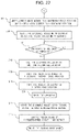
- FIG. 22 is another flowchart of folding operation in the sheet folding processing apparatus.
- FIG. 23 is a perspective view of the blade guide member
- FIGS. 24A, 24B and 24C are top explanatory views of operation of the folding blade and blade guide member
- FIG. 25 is a cross-sectional explanatory view of operation of the folding blade and blade guide member
- FIG. 26 is another cross-sectional explanatory view of operation of the folding blade and blade guide member
- FIG. 27 is still another cross-sectional explanatory view of operation of the folding blade and blade guide member
- FIG. 28 is still another cross-sectional explanatory view of operation of the folding blade and blade guide member
- FIG. 29 is still another cross-sectional explanatory view of operation of the folding blade and blade guide member
- FIGS. 30A and 30B are cross-sectional explanatory views of a deflection guide member
- FIGS. 31A and 31B are cross-sectional explanatory views of the deflection guide member
- FIGS. 32A and 32B are cross-sectional explanatory views of the deflection guide member.
- FIG. 33 is a plan view illustrating a sheet folding processing apparatus.
- FIG. 1 schematically illustrates the entire configuration of the image forming system provided with the sheet processing apparatus according to the Embodiment of the invention.
- the image forming system 100 is comprised of an image forming apparatus A and sheet processing apparatus B provided together in the apparatus A.
- the image forming apparatus A is comprised of an image forming unit A 1 , scanner unit A 2 and feeder unit A 3 .
- the image forming unit A 1 is provided with a paper feed section 2 , image forming section 3 , sheet discharge section 4 and data processing section 5 inside an apparatus housing 1 .
- the paper feed section 2 is comprised of a plurality of cassette mechanisms 2 a , 2 b and 2 c for storing image-forming sheets of respective different sizes, and feeds out sheets of the size designated from a main body control section not shown to a paper feed path 2 f .
- Each of the cassette mechanisms 2 a , 2 b and 2 c is installed to be detachable from the paper feed section 2 , and includes an integral separation mechanism for separating sheets inside on a sheet-by-sheet basis and an integral paper feed mechanism for feeding out the sheet.
- the paper feed path 2 f is provided with a transport roller for feeding the sheet supplied from each of the cassette mechanisms 2 a , 2 b and 2 c to the downstream side, and in an end portion of the path, a registration roller pair for aligning a front end of each sheet.
- the large-capacity cassette 2 d is comprised of an option unit for storing sheets of a size consumed in large quantity.
- the manual feed tray 2 e is configured to be able to supply particular sheets such as a thick-paper sheet, coating sheet and film sheet difficult to separate and feed.
- the image forming section 3 is configured using an electrophotographic scheme in this Embodiment, and is provided with a photosensitive drum 3 a that rotates, and a light emitting device 3 b for emitting an optical beam, a developing device 3 c and cleaner (not shown) arranged around the drum.
- the section shown in the figure is a monochrome printing mechanism, and is to irradiate the photosensitive drum 3 a with its circumferential surface charged uniformly with the light corresponding to an image signal by the light emitting device 3 b to optically form a latent image, and by attaching toner to the latent image with the developing device 3 c , form a toner image.
- a sheet is fed to the image forming section 3 from the paper feed path 2 f , transfer bias is applied from a transfer charging device 3 d , and the toner image formed on the photosensitive drum 3 a is thereby transferred onto the sheet.
- the sheet with the toner image transferred thereto is heated and pressurized when passing through a fuser device 6 to fuse the toner image, is discharged from a sheet discharge opening 4 b by a sheet discharge roller 4 a , and is transported to the sheet processing apparatus B described later.
- the scanner unit A 2 is provided with platen 7 a for placing an image original document, a carriage 7 b that performs reciprocating motion along the platen 7 a , a photoelectric conversion element 7 c , and a reduction optical system 7 d for guiding reflected light from the original document on the platen 7 a by the carriage 7 b to the photoelectric conversion element 7 c .
- the photoelectric conversion element 7 c performs photoelectric conversion on optical output from the reduction optical system 7 d into image data to output to the image forming section 3 as an electric signal.
- the scanner unit A 2 is provided with travel platen 7 e to read the sheet fed from the feeder unit A 3 .
- the feeder unit A 3 is comprised of a paper feed tray 8 a for stacking original document sheets, a paper feed path 8 b for guiding the original document sheet fed out of the paper feed tray 8 a to the travel platen 7 e , and a sheet discharge tray 8 c for storing the original document sheet passing through the travel platen 7 e .
- the original document sheet from the paper feed tray 8 a is read by the carriage 7 b and reduction optical system 7 d , in passing through the travel platen 7 e.
- FIG. 2 is a configuration explanatory view of the sheet processing apparatus B according to this Embodiment.
- the sheet processing apparatus B is provided with an apparatus housing 11 provided with a carry-in opening 10 to introduce a sheet from the image forming apparatus A.
- the apparatus housing 11 is positioned and disposed in accordance with the housing 1 of the image forming apparatus A so as to communicate the carry-in opening 10 to the sheet discharge opening 4 b of the image forming apparatus A.
- the sheet processing apparatus B is provided with a sheet carry-in path 12 for transporting a sheet introduced from the carry-in opening 10 , a first sheet discharge path 13 a branched off from the sheet carry-in path 12 , a second sheet discharge path 13 b , a third sheet discharge path 13 c , a first path switch portion 14 a , and a second path switch portion 14 b .
- Each of the first path switch portion 14 a and the second path switch portion 14 b is comprised of a flapper guide for changing a transport direction of a sheet transported in the sheet carry-in path 12 .
- the first path switch portion 14 a switches between a mode for guiding a sheet from the carry-in opening 10 in a direction of the first sheet discharge path 13 a to transport in a lateral direction without modification and the second sheet discharge path 13 b to transport downward, and another mode for guiding to the third sheet discharge path 13 c to transport upward.
- the first sheet discharge path 13 a and second sheet discharge path 13 b are communicated so as to be able to reverse the transport direction of the sheet once introduced to the first sheet discharge path 13 a to switchback-transport to the second sheet discharge path 13 b.
- the second path switch portion 14 b is disposed on the downstream side of the first path switch portion 14 a , with respect to the transport direction of the sheet transported in the sheet carry-in path 12 .
- the second path switch portion 14 b switches between a mode for introducing the sheet passing through the first path switch portion 14 a to the first sheet discharge path 13 a , and another mode for switchback-transporting the sheet once introduced to the first sheet discharge path 13 a to the second sheet discharge path 13 b.
- the sheet processing apparatus B is provided with a first processing section B 1 , second processing section B 2 and third processing section B 3 which perform respective different post-processing. Further, in the sheet carry-in path 12 is disposed a punch unit 15 for punching a punch hole in the carried-in sheet.
- the first processing section B 1 is a binding processing section for collecting a plurality of sheets carried out of a sheet discharge opening 16 a in a downstream end of the first sheet discharge path 13 a with respect to the transport direction of the sheet transported in the sheet carry-in path 12 to collate and perform binding processing, and discharging to a stacking tray 16 b provided outside the apparatus housing 11 . Further, the first processing section B 1 is provided with a sheet transport apparatus 16 c for transporting the sheet or a bunch of sheets, and a binding processing unit 16 d for performing the binding processing on the bunch of sheets. In the downstream end of the first sheet discharge path 13 a is provided a discharge roller pair 16 e to discharge the sheet from the sheet discharge opening 16 a and to switchback-transport from the first sheet discharge path 13 a to the second sheet discharge path 13 b.
- the second processing section B 2 is a folding processing section for making a bunch of sheets using a plurality of the sheets switchback-transported from the second sheet discharge path 13 b , performing the binding processing on the bunch of the sheets, and then, performing folding processing.
- the second processing section B 2 is provided with a folding processing apparatus F for performing the folding processing on the carried-in sheet or bunch of sheets, and a binding processing unit 17 a disposed on the immediately upstream side of the folding processing apparatus F along the sheet transport direction of the sheet transported to the second sheet discharge path 13 b to perform the binding processing on the bunch of sheets.
- the bunch of sheets subjected to the folding processing is discharged to a stacking tray 17 c provided outside the apparatus housing 11 by a discharge roller 17 b.
- the third processing section B 3 performs jog sorting for sorting sheets fed from the third sheet discharge path 13 c into a group for offsetting by a predetermined amount in a sheet width direction orthogonal to the transport direction to collect, and another group for collecting without offsetting.
- the jog-sorted sheets are discharged to a stacking tray 18 provided outside the apparatus housing 11 , and a bunch of sheets subjected to offset and a bunch of sheets without being offset are stacked.
- FIG. 3 schematically illustrates the entire configuration of the second processing section B 2 .
- the second processing section B 2 is provided with the folding processing apparatus F for folding a bunch of sheets, which are carried in from the second sheet discharge path 13 b , collected and collated, in two, and the binding processing unit 17 a for performing the binding processing on a bunch of sheets prior to the folding processing.
- the binding processing unit 17 a shown in the figure is a stapler apparatus for hitting a staple to bind the bunch of sheets.
- a sheet transport path 20 is connected to the second sheet discharge path 13 b .
- the sheet stacking tray 21 constituting a part of the sheet transport path is provided to position the sheet undergoing the folding processing to stack.
- the binding processing unit 17 a and its staple receiving portion 17 d are provided in opposed positions with the sheet transport path 20 sandwiched therebetween.
- a folding roller pair 22 as a folding rotating body pair is arranged to be opposed to one surface of the sheet or a bunch of sheets stacked in the sheet stacking tray.
- the folding roller pair 22 is comprised of a pair of folding rollers 22 a , 22 b with roller surfaces thereof mutually brought into press-contact, and a nip portion 22 c that is a press-contact portion thereof is disposed toward the sheet stacking tray 21 .
- the folding rollers 22 a , 22 b are disposed parallel on the upstream side and downstream side along a carry-in direction of the sheet carried in the sheet stacking tray 21 from the upstream side above to the downstream side below, with respective distances from the sheet stacking tray 21 being approximately equal.
- a rotating portion of the folding rotating body pair is not limited to the folding rollers 22 a , 22 b of this Embodiment, and is capable of being comprised of a rotating belt and the like.
- the folding roller pair 22 is capable of being configured by arranging a plurality of folding rollers (rotating bodies) continuously in series along a shaft direction of each of the folding rollers 22 a , 22 b.
- roller circumferential surfaces thereof have first roller surfaces 22 a 2 , 22 b 2 with certain radiuses R 1 , and second roller surfaces 22 a 3 , 22 b 3 with distances from the rotation shaft centers of the rotation shafts smaller than the radius R 1 of the first roller surface, respectively.
- the first roller surfaces 22 a 2 , 22 b 2 are formed of rubber materials and the like with a relatively high coefficient of friction.
- the second roller surfaces 22 a 3 , 22 b 3 are formed of plastic resin materials and the like with a coefficient of friction smaller than the coefficient of the first roller surfaces 22 a 2 , 22 b 2 .
- the rotation shafts 22 a 1 , 22 b 1 of the folding rollers 22 a , 22 b are driven to rotate by a common drive section such as a drive motor.
- a common drive section such as a drive motor.
- a folding blade 23 is disposed on the opposite side to the folding roller pair 22 across the sheet stacking tray 21 .
- the folding blade 23 is supported by a blade carrier 24 with its front edge directed toward the nip portion 22 c of the folding roller pair 22 .
- the blade carrier 24 is provided to be able to travel by a shift section comprised of a cam member and the like, in a direction traversing the sheet stacking tray 21 at an approximately right angle i.e. in a direction crossing the transport direction of the sheet transported to the sheet stacking tray 21 from the second sheet discharge path 13 b.
- cam members 25 (only one is shown in the figure) comprised of a pair of mutually mirror symmetrical eccentric cams are provided in opposed positions.
- the cam member 25 rotates by a drive section such as a drive motor around a rotation shaft 25 a provided in the eccentric position as the center.
- a cam groove 25 b is formed along its outer edge.
- the blade carrier 24 is provided with a cam pin 24 c that is fitted into the cam groove 25 b slidably as a cam follower.
- the blade carrier 24 reciprocates and travels in directions for approaching and separating from the sheet stacking tray 21 .
- the cam member 25 When the cam member 25 is rotated by the drive motor, the blade carrier 24 reciprocates and travels in directions for approaching and separating from the sheet stacking tray 21 .
- the folding blade 23 linearly to be able to proceed and retract, between an initial position that is a position in which a front edge of the folding blade 23 does not enter the sheet transport path formed of the sheet stacking tray 21 , and a maximum push position in which the front edge is nipped by the nip portion 22 c of the folding roller pair 22 , along a push path for connecting between both positions.
- a regulation stopper 26 for bringing the front end of the carried-in sheet in the transport direction into contact therewith to regulate.
- the regulation stopper 26 is provided to be able to move up and down along the sheet stacking tray 21 by a sheet up-and-down mechanism 27 .
- the sheet up-and-down mechanism 27 of this Embodiment is a conveyor belt mechanism which is disposed on the back side of the sheet stacking tray 21 , below the blade carrier 24 when the carrier is in the initial position that is a position in which the front edge of the folding blade 23 does not enter the sheet transport path formed of the sheet stacking tray 21 , and which is comprised of a pair of pulleys 27 a , 27 b respectively disposed near an upper end and lower end of the sheet stacking tray 21 along the tray 21 , and a conveyor belt 27 c looped between both of the pulleys.
- the regulation stopper 26 is fixed onto the conveyor belt 27 c .
- the regulation stopper 26 By rotating the pulley 27 a or 27 b on the drive side by a drive section such as a drive motor, the regulation stopper 26 moves up and down between a lower end position and a desired height position shown in FIG. 3 , and is thereby capable of shifting the sheet or bunch of sheets along the sheet stacking tray 21 .
- the folding processing apparatus F of this Embodiment is further provided with a sheet side-portion alignment mechanism to align side edges of the sheet carried in the sheet stacking tray 21 to perform alignment.
- the sheet side-portion alignment mechanism includes a pair of sheet side-portion alignment members 28 a , 28 b disposed symmetrically on opposite sides of the sheet stacking tray 21 in the sheet width direction (direction orthogonal to the sheet transport direction).
- FIG. 4 is a plan schematic view obtained by viewing the folding processing apparatus F from above.
- the sheet side-portion alignment members 28 a , 28 b are held to be capable of shifting to be able to relatively approach and separate in the sheet width direction. With respect to the sheet which is transported to the sheet stacking tray 21 and of which the front end strikes the regulation stopper 26 , the sheet side-portion alignment members 28 a , 28 b are shifted, and thereby align positions of the sheet in the width direction.
- the sheet processing apparatus B of this Embodiment is capable of performing inward three-fold processing on the sheet transported to the sheet stacking tray 21 that is the sheet transport path, by the folding processing apparatus F.
- the inward three-fold processing is processing for folding in three so that an end portion on one side of a sheet folded by first folding processing is folded inside the sheet folded by second folding processing, when the sheet is folded in two by the first folding processing and the second folding processing is performed on the sheet in a portion different from a first fold position.
- FIGS. 5A to 11B illustrate, in cross-sectional schematic views, motion of each section according to a flow of a sheet S when the inward three-fold processing is executed.
- the sheet stacking tray 21 of this Embodiment is formed, while being inclined with respect to the vertical direction, and while the surface on one side of the sheet S is guided by a guide face 21 a forming the sheet stacking tray 21 , the sheet is transported so as to fall with a sheet front end S 1 down and a sheet rear end S 2 up, and is halted when the sheet front end is struck by the regulation stopper 26 ( FIG. 5A ).
- a position of the regulation stopper 26 is disposed so that the first fold position of the sheet S with the sheet front end S 1 struck is a position opposed to the folding blade 23 .
- the folding blade 23 is disposed in the position for pushing out the sheet S toward the folding roller pair 22 from the side of the guide face 21 a of the sheet stacking tray 21 .
- the guide face 21 a of the sheet stacking tray 21 and the folding roller pair 22 are disposed in positions that correspond to each other with the sheet S therebetween.
- the folding blade 23 is operated to fold the sheet S in two, and pushes out the folded portion to the nip portion 22 c of the folding roller pair 22 ( FIG. 5B ).
- the folding roller pair 22 and discharge roller 17 b are driven to rotate forward, and draw the sheet S into the folding roller pair 22 and discharge roller 17 b .
- the sheet S is pressed by the nip portion of the folding roller pair 22 , and the first folding processing is performed ( FIG. 6A ).
- sheet transport is halted at the time the sheet rear end S 2 subjected to the first folding processing arrives at a predetermined position ( FIG. 6B ), and the folding roller pair 22 and discharge roller 17 b are driven to rotate backward to execute switchback-transport processing.
- the sheet rear end S 2 is an end portion (hereinafter, referred to as “fold-in end portion”) which is folded inside the sheet folded by the second folding processing.
- the switchback-transport processing the fold-in end portion S 2 is pressed downward (direction of the sheet stacking tray 21 where the sheet front end S 1 exists) by an L-shaped press guide member 30 ( FIG.
- the press guide member 30 guides the sheet S which is again transported in the direction of the sheet stacking tray 21 where the regulation stopper 26 is disposed ( FIG. 7B ).
- the configuration and operation of the press guide member 30 will be described later in detail.
- the folding blade 23 is operated again to push the sheet S to the nip portion 22 c of the folding roller pair 22 ( FIG. 10A ).
- a blade guide member 40 that is a push guide member disposed above the folding blade 23 protrudes, and the fold-in end portion S 2 of the sheet is thereby guided to be pushed into the nip portion 22 c ( FIG. 10B ).
- the configuration and operation of the blade guide member 40 will be described later also in detail.
- the sheet S fed to the folding roller pair 22 by push of the folding blade 23 passes through the nip portion 22 c and is thereby subjected to the second folding processing ( FIG. 11A ), and the inward three-folded sheet S is discharged by the discharge roller 17 b ( FIG. 11B ).
- FIG. 12 is a perspective view of the folding processing apparatus F in a state in which the press guide member 30 is exposed
- FIG. 13 is a view illustrating a relationship between a rotation locus of the press guide member 30 and another member.
- FIGS. 14A to 14C contain operation explanatory views of the press guide member 30 .
- the press guide member 30 presses the fold-in end portion S 2 of the sheet downward, and guides to transport to the sheet stacking tray 21 , in switchback-transporting the sheet with the first folding processing executed.
- the press guide member 30 is also a direction change member to change the direction of the fold-in end portion S 2 of the sheet to the direction of the sheet stacking tray 21 where the sheet front end S 1 exists, in switchback-transporting the sheet with the first folding processing executed.
- the press guide member 30 is disposed on the side opposite to the side on which the folding roller pair 22 is disposed with the sheet S guided to the guide face 21 a of the sheet stacking tray 21 therebetween.
- three members are attached, at approximately regular intervals, to a rotation shaft 31 that is a support member disposed in the sheet width direction.
- Two members on opposite sides are disposed in positions for enabling the members to come into contact with opposite end portions of the sheet S transported in the sheet stacking tray 21 , and one member in the center is disposed in a position for enabling the member to come into contact with substantially the center of the transported sheet in the width direction.
- the above-mentioned press guide member 30 is capable of shifting by a shift section.
- the rotation shaft 31 is coupled to a press guide motor 33 via a drive transfer member 32 such as a drive belt, and it is configured that the rotation shaft 31 is rotated by drive of the press guide motor 33 , and that integrally therewith, three press guide members 30 are capable of rotating.
- the press guide member 30 has a rotation portion 30 a capable of rotating around the rotation shaft 31 as the center, and a guide portion 30 b that is a first guide face for guiding the sheet S undergoing switchback-transport, and is comprised of a member of L-shaped cross section where the guide portion 30 b is coupled at an approximately right angle, while being continued to the rotation portion 30 a . Then, a portion between the rotation portion 30 a and the guide portion 30 b i.e. a corner portion of the shape of an L that is the front end of the rotation portion 30 a is formed as a press portion 30 c for pressing the sheet S.
- a notch is formed in the guide face 21 a , and the press guide member 30 is provided to be exposed from the notch. Then, when the sheet S is carried in the sheet stacking tray 21 , the member retracts to a retract position (see FIG. 5A ). When the member is in the retract position, the rotation portion 30 a is provided to be substantially the same plane as the guide face 21 a . Therefore, the rotation portion 30 a functions as a part of the guide face 21 a , and acts as a guide face (second guide face) for guiding the sheet carried in the sheet stacking tray 21 . Then, it is essential only that the guide portion 30 b does not protrude from the guide face 21 a when the press guide member 30 is in the retract position, and it is thereby possible to reduce storage space of the press guide member 30 in the retract state.
- the rotation shaft 31 that is the rotation center of the press guide member 30 of this Embodiment is disposed on the upstream side from a nip line L 1 for connecting between the nip portion 22 c of the folding roller pair 22 and the front edge portion of the folding blade 23 , in the transport direction in which the sheet S is carried in the sheet stacking tray 21 , and is disposed on the side opposite to the side on which the folding roller pair 22 is disposed with the guide face 21 of the sheet stacking tray 21 therebetween.
- the rotation shaft 31 of this Embodiment is disposed on the downstream side, in the transport direction, from a shaft line L 2 which passes through the rotation shaft 22 a 1 of the folding roller disposed on the upstream side from the nip line L 1 in the sheet transport direction in the folding rollers 22 a , 22 b i.e. the folding roller 22 a existing on the side closer to the rotation shaft 31 , and which is parallel with the nip line L 1 .
- the rotation portion 30 a is configured to rotate in a direction in which the press portion 30 c presses the sheet S to the side for switchback-transport.
- the press portion 30 c changes the direction of the fold-in end portion S 2 of the sheet to the direction of the sheet stacking tray 21 where the sheet front end S 1 exists.
- the press guide member 30 stays in the position without changing, and is thereby capable of guiding the fold-in end portion S 2 to the downstream side in the sheet transport direction, in which the sheet S is received in the sheet stacking tray 21 before the first folding processing is performed.
- the press portion 30 c rotates to a guide position where the portion is rotated to a position of the guide face 21 a , the press portion 30 c comes into contact with the sheet, then presses the fold-in end portion S 2 of the sheet down so as to draw into the guide face 21 a side from the nip portion 22 c side, and guides the portion in a direction of the sheet stacking tray 21 where the regulation stopper 26 is disposed. Therefore, even when the fold-in end portion S 2 of the sheet is curled upward, the sheet des not proceed toward above in the sheet stacking tray 21 , and is reliably transported toward below.
- a length of the rotation portion 30 a of the press guide member 30 of this Embodiment i.e. a length from the rotation shaft 31 that is a rotation support to the press portion 30 c is configured to be longer than the shortest distance to the first roller surface 22 a 2 in the folding roller 22 a on the side closer to the rotation shaft 31 , and be shorter than the shortest distance to the second roller surface 22 a 3 , in two folding rollers 22 a , 22 b , as shown in FIG. 13 .
- the portion 30 a does not interfere with the folding roller pair 22 .
- the press portion 30 c presses in a position nearer the nip portion 22 c , and guides to the sheet stacking tray 21 with more reliability.
- the rotation shaft 31 in order for the rotating press guide member 30 not to interfere with the folding blade 23 , the rotation shaft 31 should be disposed in a position apart from the folding blade 23 in the sheet transport direction. In this case, as a result, the rotation shaft 31 should be disposed in a position also apart from the folding roller pair 22 .
- the rotation shaft 31 is configured to be disposed between the nip line L 1 and the rotation shaft line L 2 in the sheet transport direction, without increasing the length of the rotation portion 30 a unnecessarily, it is possible to bring the position for the press portion 30 c to press the sheet undergoing switchback-transport closer to the nip portion 22 c.
- the folding roller pair as well as using the rollers with different diameters having the first roller surfaces 22 a 2 , 22 b 2 and second roller surfaces 22 a 3 , 22 b 3 with the diameters being different as in this Embodiment, it is also possible to use a roller pair with certain roller diameters, and in this case, it is necessary to make the length of the rotation portion 30 a shorter than the shortest distance to the outer region of the folding roller on the side closer to the rotation shaft.
- the press guide member 30 of this Embodiment is in the shape that the guide portion 30 b is inside a rotation locus L 3 of the rotation portion 30 a , and does not protrude outside the region.
- the sheet is returned to the sheet stacking tray 21 , while being guided by the press guide member 30 .
- the press guide member 30 is returned to the retract position.
- the member is shifted to the backward transport guide position protruding to the sheet transport path side slightly more than the guide face 21 a , so that the rotation portion 30 a that is the second guide face of the press guide member 30 is a guide of the sheet S transported in the reverse direction in the sheet stacking tray 21 (see FIG. 8B ).
- the regulation stopper 26 is moved up, and the sheet is transported backward so that the second fold position is in the position opposed to the folding blade 23 .
- the sheet S is guided by the rotation portion 30 a of the press guide member 30 , and therefore, is transported, without being caught in the notch for attachment of the press guide member formed in the guide face 21 a , and the like (see FIG. 9A ).
- the press guide member 30 is shifted to the retract position, and the folding blade 23 is operated to execute second folding operation.
- the blade guide member 40 provided above the folding blade 23 guides the fold-in end portion S 2 of the sheet (see FIG. 10B ).
- FIGS. 15A and 15B contain rotation explanatory views of the blade guide member 40
- FIGS. 16A to 19B contain views illustrating operation of the folding blade 23 and blade guide member 40 in executing the second folding processing on the sheet.
- the blade guide member 40 is to shift in a push direction of the folding blade 23 , and with respect to the folding blade 23 , to guide, in the push direction, the sheet end portion on the fold side formed by the first folding processing i.e. the sheet fold-in end portion S 2 so as to guide to the nip portion 22 c of the folding roller pair 22 . Therefore, as shown in FIGS.
- the blade guide member 40 has a contact portion 40 a for coming into contact with the sheet rear end, and a fit hole portion 40 b having a partial notch is formed in an end portion on one side of the contact portion 40 a , and is fitted rotatably into a shaft portion 40 f formed in a base portion 40 e .
- an arm portion 40 c is formed integrally, and an engagement protruding portion 40 d is formed in an end portion of the arm portion 40 c .
- the engagement protruding portion 40 d is engaged slidably in a long hole 50 formed in a frame of the sheet processing apparatus B.
- the long hole 50 is formed substantially parallel with the guide face 21 a of the sheet stacking tray 21 in the upper vicinity of the blade carrier 24 .
- the above-mentioned base portion 40 e is attached to the blade carrier 24 slidably in a direction parallel to a shift direction of the blade carrier 24 . Then, a tensile spring 51 is attached to between a locking portion 40 e 1 formed in the base portion 40 e and a locking portion 24 a formed in the blade carrier 24 .
- the blade carrier 24 is provided with a press protruding portion 24 b capable of coming into contact with the base portion 40 e to press.
- the press protruding portion 24 b is provided in the blade carrier 24 rotatably, and is biased in a counterclockwise direction in FIGS. 15A and 15B by a coil spring 52 attached to the rotation shaft.
- the coil spring 52 provided in the press protruding portion 24 b acts as the so-called torque limiter, and rotates clockwise when a predetermined force or more in the clockwise direction is applied to the press protruding portion 24 b.
- the engagement protruding portion 40 d is guided by the long hole 50 to slide downward, and the contact portion 40 a rotates around a shaft portion 40 f as the center.
- the shaft portion 40 f is provided in one end of the contact portion 40 a closer to the folding blade 23 .
- the one end refers to a region between the center of the contact portion 40 a and the end portion closer to the folding blade 23 .
- the shaft portion 40 f is provided in any region closer to the folding blade 23 side than the center of the contact portion 40 a . Accordingly, in a state of FIG.
- an angle with respect to the shift direction of the blade carrier 24 i.e. the shift direction of the folding blade 23 is an approximately right angle, and the contact portion 40 a is in the standing state. Then, as the blade carrier 24 shifts in a direction in which the folding blade 23 is pushed, as shown in FIG. 15B , the other end of the contact portion 40 a shifts so as to approach a shift locus of the shaft portion 40 f that is the rotation center thereof i.e. so as to fall to the upstream side in the push direction of the folding blade 23 .
- the angle of the contact portion 40 a with respect to the shift direction of the carrier 24 changes to an acute angle (the angle on the upstream side in the push direction is decreased).
- one end of the contact portion 40 a is configured to be rotatable around the shaft portion as the center, while the end portion of the arm portion 40 c provided to extend in the other end of the contact portion 40 a is configured to be slidable along the long hole 50 , and the blade guide member 40 is thereby capable of changing the angle with respect to the shift direction in conjunction with the shift of the blade guide member 40 , without being provided with any particular drive section.
- a protruding portion 40 f 1 is formed in the shaft portion 40 f that is a rotation axis of the contact portion 40 a .
- the notch formed in the fit hole portion 40 b fitted into the shaft portion 40 f is formed to be wider than a width of the protruding portion 40 f 1 , and the blade guide member 40 is capable of rotating in a range of the notch.
- the contact portion 40 a and arm portion 40 c are comprised of linear members in cross section, and the arm portion 40 c is formed at a predetermined angle with respect to the contact portion 40 a .
- the contact portion 40 a is substantially the same plane as the guide face 21 a when the blade guide member 40 is in the home position, the end portion on the side provided with the engagement protruding portion 40 d of the arm portion 40 c is in the position apart from the guide face 21 a on the side opposite to the side on which the folding roller pair 22 exits.
- the end portion is in the position apart from the guide face 21 a on the side of the direction for returning the folding blade 23 from the nip portion 22 c side to the home position. Therefore, it is possible to arrange the long hole 50 in which the engagement protruding portion 40 d engages apart from the guide face 21 a on the side opposite to the side on which the folding roller pair 22 exists, and to arrange in the position of not interfering with the guide face 21 a . Accordingly, in the state in which the blade guide member 40 is in the home position, it is possible to configure so that the contact portion 40 a functions as a guide portion of a sheet transported in the sheet stacking tray 21 .
- FIG. 16A illustrates a state in which the blade carrier 24 is in the home position, and at this point, the blade guide member 40 is also in the state of the home position.
- the “push direction” refers to a direction in which the blade carrier 24 pushes out the folding blade 23 to the nip portion 22 c of the folding roller pair 22 from the position of the home position
- “return direction” refers to a direction in which the blade is returned to the home position from the nip portion 22 c side.
- the front edge of the folding blade 23 is substantially the same plane as the guide face 21 a , or on the return-direction side than the guide face 21 a (first position), and is separated from the sheet S in the sheet stacking tray 21 . Therefore, the sheet, which is guided by the guide face 21 a and is transported in the sheet stacking tray 21 , is not caught in the blade front edge.
- this state may be a first position.
- the contact portion 40 a of the blade guide member 40 is in a position in contact with the rotation shaft 31 .
- the press protruding portion 24 b is separated from the base portion 40 e.
- the cam member 25 is rotated to shift the blade carrier 24 in the push direction. Then, the press protruding portion 24 b comes into contact with the base portion 40 e , and the blade guide member 40 shifts in the push direction integrally with the blade carrier 24 and folding blade 23 ( FIG. 16B ). At this point, it is configured that the front edge portion of the folding blade 23 protrudes to the push direction more than the front end portion of the blade guide member 40 .
- the folding blade front edge portion protrudes by a predetermined amount. Then, as shown in FIG. 17A , the front edge of the folding blade 23 comes into contact with the sheet S which is subjected to the first folding processing and is halted in the sheet stacking tray 21 with the second fold position opposed to the folding blade 23 (second position). At this point, since the front edge of the folding blade 23 protrudes in the push direction more than the blade guide member 40 as described previously, the folding blade 23 comes into contact with the fold position of the sheet S faster than the blade guide member 40 . Therefore, by pushing by the folding blade 23 , the folding blade front edge opposed to the fold position of the sheet is accurately brought into contact, without being displaced from the fold position of the sheet, and the folding processing is executed in the proper fold position.
- the folding blade front edge does not need to always protrude with respect to the blade guide member 40 , and when the folding blade front edge is essentially in the same position as the blade guide member 40 in the push direction, it is possible to suppress displacement when the blade front edge comes into contact with the fold position of the sheet.
- the second fold position of the sheet S is pushed toward the nip portion 22 c of the folding roller pair 22 by the folding blade 23 .
- the contact portion 40 c of the blade guide member 40 comes into contact with the fold-in end portion S 2 of the sheet subjected to the first folding, and guides so as to push the fold-in end portion S to the nip portion 22 c ( FIG. 17B ).
- the blade guide member 40 guides the fold-in end portion S 2 of the sheet to the nip portion 22 c , the fold-in end portion S 2 of the sheet travels to the nip portion 22 c , without being turned up. Further, in approaching the nip portion 22 c , there is the risk that the pushed blade guide member 40 interferes with outer regions of the folding rollers 22 a , 22 b .
- the angle of the contact portion 40 a with respect to the push direction changes to an acute angle (changes from the state of FIG. 17A to the state of FIG. 17B ). Therefore, the contact portion 40 a is capable of further entering the vicinity of the nip portion 22 c , and it is possible to reliably guide the fold-in end portion S 2 of the sheet to the nip portion.
- the blade guide member 40 is regulated not to further shift in the push direction.
- the front end (end portion on the folding roller pair 22 side with respect to the push direction) of the blade guide member 40 protrudes to the nip portion 22 c side more than the tangent line (of two folding rollers 22 a , 22 b ) for connecting between outer regions of the folding roller 22 a and folding roller 22 b on the sheet stacking tray 21 side.
- the press protruding portion 24 b rotates clockwise against the biasing force of the coil spring 52 , and moves into a lower portion of the base portion 40 e .
- the press protruding portion 24 b does not press the blade guide member 40 , while the blade guide member 40 is halted, only the folding blade 23 shifts in the push direction, and the blade front edge protrudes maximally to shift to a position (third position) for pushing the sheet S to the nip portion 22 c .
- the front edge of the folding blade 23 at this point protrudes more significantly than the front end of the contact portion 40 a of the blade guide member 40 .
- a distance from the blade front edge to the contact portion front end in the third position is longer than the distance from the blade front edge to the contact portion front end in the second position.
- the blade guide member 40 when a certain load or more is imposed, the blade guide member 40 is capable of shifting relatively in the return direction with respect to the folding blade 23 , against the frictional force with the press protruding portion 24 b in press-contact with the bottom of the base portion 40 e by the biasing force of the coil spring 52 .
- the blade guide member 40 is not broken.
- the blade carrier 24 shifts in the return direction together with the folding blade 23 ( FIG. 18B ).
- the blade guide member 40 since the press protruding portion 24 b is brought into press-contact with the base portion 40 e of the blade guide member 40 by the biasing force of the coil spring 52 , the blade guide member 40 also shifts in the return direction integrally with the blade carrier 24 i.e. concurrently with the folding blade 23 by the friction force between the press protruding portion 24 b and the bottom of the base portion 40 e.
- the blade guide member 40 when the blade carrier 24 shifts in the return direction, the folding blade 23 and blade guide member 40 shift in the return direction at the same time, and before the blade carrier 24 and folding blade 23 return to the home positions, the blade guide member 40 returns to the home position. In other words, the blade guide member 40 retracts from the sheet drawn by the folding roller pair 22 and discharge roller 17 b faster than the folding blade 23 . Therefore, a transport load by the blade guide member 40 is reduced on the sheet S drawn by the discharge roller 17 b and the like.
- the blade guide member 40 is disposed in two predetermined positions in the sheet width direction.
- the push front edge portion 23 a is formed in six portions to protrude substantially at regular intervals in the sheet width direction on the push side.
- the push front edge portion 23 a pushes out the sheet, the sheet is thereby pushed to the nip portion 22 c of the folding roller pair 22 , and the folding processing is executed.
- the blade guide members 40 are disposed above the push front edge portions 23 a 1 among the six push front edge portions 23 a i.e.
- the fold-in end portion S 2 is guided by the blade guide members 40 on the opposite sides in the width direction.
- the blade guide member 40 is disposed above all the push front edge portions 23 a ( 23 a 1 ) formed in the six portions, but when the member is disposed above all the portions, the number of parts increases. In contrast thereto, in this Embodiment, as described previously, since the blade guide member 40 is disposed in positions of two push front edge portions 23 a 1 formed on the opposite end portion sides in the sheet width direction, it is possible to decrease the number of parts.
- the two blade guide members 40 are not disposed in the opposite end portions in the sheet width direction of the minimum-width sheet capable of being transported to the sheet stacking tray 21 , but are disposed above the push front edge portions 23 a 1 formed closer to the center slightly than the opposite end portions. This is because it is effective to push portions closer to the center slightly than the end portions in the width direction of the sheet, in pushing out the sheet by the push front edge portions 23 a , and the blade guide member 40 is disposed corresponding to the position of the push front edge portion 23 a 1 .
- the press guide members 30 of this Embodiment are disposed on the outer sides than the two blade guide members 40 in the sheet width direction.
- two press guide members 30 are disposed substantially at the same distance as the width of the minimum-size sheet capable of being processed in the folding processing apparatus F, and in performing the folding processing on the minimum-size sheet, are disposed in positions for enabling opposite ends of the sheet in the width direction to be pressed and guided.
- the press guide member 30 capable of pressing and guiding the center in the sheet width direction is provided, and total three press guide members 30 are provided.
- the minimum-size sheet capable of being processed in the folding processing apparatus F in this Embodiment is A4, and a length of the width in the short direction of the general A4-size sheet is 210 mm.
- a length in the sheet width direction is formed to be 18 mm, a length for connecting between respective end portions on the outer sides of the two press guide members 30 by a straight line is 226 mm longer than the sheet width of the A4-size sheet, and the end portion of the A4-size sheet in the width direction overlaps a part of the face of the press guide member 30 closer to the center in the width direction by 10 mm on each of the sides.
- the maximum-size sheet capable of being processed in the folding processing apparatus F is A3, and a length of the width in the short direction of the general A3-size sheet is 297 mm.
- the press guide member 30 presses the fold-in end portion S 2 of the sheet to guide so as to return to the sheet stacking tray 21 , it is effective at preventing turn-up to press and guide the opposite end portions in the sheet width direction. Therefore, two press guide members 30 are disposed on the outer sides in the sheet width direction than the blade guide members 40 .
- the press guide members 30 disposed on the opposite sides in the sheet width direction are disposed substantially at the same distance as the width of the minimum-size sheet, and the blade guide members 40 are disposed at a distance shorter than the width of the minimum-size sheet on the inner sides than the members 30 .
- push front edge portions 23 a 2 are disposed on outer sides of the press guide members 30 , respectively.
- the push front edge portion 23 a 2 are to prevent a wrinkle from occurring in the sheet in pushing the sheet large in size in the sheet width direction, and are disposed on inner sides than the opposite end portions of the maximum-size sheet (it is not necessary to particularly provide in an apparatus where handling sheets are determined to be only the minimum size described above.)
- it is desirable that the press guide member 30 and blade guide member 40 are disposed in accordance with the minimum-size sheet, and when necessary, the push front edge portion 23 a 2 may be disposed additionally on the outer side of the press guide member 30 .
- the blade guide members 40 are disposed on the inner sides of two press guide members 30 in the sheet width direction
- the push front edge portions 23 a 1 are disposed corresponding to the positions of the blade guide members 40
- the push front edge portions 23 a 2 may further be disposed on the outer sides of two press guide members 30 corresponding to the sheet size to handle.
- this Embodiment illustrates the aspect where two push front edge portions 23 a 1 provided with the blade guide members 40 are provided with the center of the sheet S therebetween, and the configuration may be made using one push front edge portion 23 a 1 and one blade guide member 40 .
- the press guide member 30 is disposed between the push front edge portion 23 a 1 and the push front edge portion 23 a 2 so as not to interfere with the push front edge portions 23 a 1 , 23 a 2 when the press guide member 30 shifts to the guide position. Accordingly, it is possible to arrange each member in saved space.
- a control section 60 controls drive of a folding roller motor 61 for driving and rotating the folding roller pair 22 , a discharge roller motor 62 for driving and rotating the discharge roller 17 b , and a regulation stopper motor 63 for operating the sheet up-and-down mechanism 27 to move the regulation stopper 26 up and down. Further, similarly, the control section 60 controls drive of a cam motor 64 for driving the cam member 25 to operate the blade carrier 24 , and a press guide motor 33 for rotating the press guide member 30 .
- FIGS. 21 and 22 are flowcharts showing a drive control procedure when the sheet S is transported to the sheet stacking tray 21 , the sheet front end strikes the regulation stopper halted at a predetermined position, and the folding processing is executed from the state in which the first fold position is in the position opposed to the folding blade 23 .
- the cam motor 64 is driven to shift the blade carrier 24 in the push direction, and the folding blade 23 comes into contact with the first fold position of the sheet S to push to the nip portion 22 c (S 1 ).
- the folding roller motor 61 and discharge roller motor 62 are driven to drive the folding roller pair 22 and discharge roller 17 b to rotate forward (S 2 ).
- Each of the motors uses a pulse motor, and when the motor is driven, the number of drive pulses thereof is counted.
- the folding processing is performed on the sheet S pushed to the nip portion 22 c of the folding roller pair 22 by push of the above-mentioned folding blade 23 for a period during which the sheet S is nipped and transported by the folding roller pair 22 , and the sheet is transported by the discharge roller 17 b constituting the sheet transport section together with the folding roller pair 22 without any modification.
- the folding roller motor 61 is halted when the second roller surfaces 22 a 3 , 22 b 3 of the folding rollers 22 a , 22 b are opposed to each other (S 5 , S 6 ).
- the folding roller pair 22 does not nip the sheet, and the sheet is transported by the discharge roller 17 b .
- the sheet is transported by the discharge roller 17 b , while being guided by the second roller surfaces 22 a 3 , 22 b 3 with a small coefficient of friction.
- the predetermined region is a region between the rotation locus L 3 of the press guide member 30 for the fold-in end portion S 2 of the sheet S and the guide face 21 a of the sheet stacking tray 21 (see FIG. 14A ).
- the press guide motor 33 After halting the fold-in end portion S 2 of the sheet S within the region, the press guide motor 33 is driven to rotate the press guide member 30 so as to arrive at a position (position shown in FIG. 14C ) where the guide portion 30 b of the press guide member 30 is capable of guiding the switchback-transported sheet S (S 9 ). Further, together with rotation of the press guide member 30 , the regulation stopper motor 63 is driven to shift the regulation stopper 26 to a position for enabling the switchback-transported sheet S to be received.
- the discharge roller motor 62 and folding roller motor 61 are driven to rotate backward (S 10 ).
- the discharge roller 17 b and folding roller pair 22 rotate backward, and the sheet S is switchback-transported.
- the sheet since the sheet is guided by the press guide member 30 , the sheet does not generate a transport failure, and is switchback-transported in the direction of the sheet stacking tray 21 where the regulation stopper 26 is disposed.
- a velocity at which the press guide member 30 is returned to the retract position (see FIG. 14A ) from the guide position (see FIG. 14C ) is set to be faster than a velocity at which the press guide member 30 is shifted to the guide position from the retract position.
- the velocity is decreased to rotate so as to press the sheet S halted for switchback-transport and change the direction.
- shifting from the guide position to the retract position by returning faster, it is possible to hasten the timing of executing next operation.
- the regulation stopper motor 63 is driven to shift so that the second fold position of the sheet S is the position opposed to the folding blade 23 (S 14 ).
- the cam motor 64 , folding roller motor 61 and discharge roller motor 62 are driven to execute second folding operation (S 15 to S 17 ).
- the motor to drive each member is provided individually, and it is also possible to drive each member by using a common motor and switching drive with a clutch and the like.
- the Embodiment described previously illustrates the example where the angle of the contact portion 40 a with respect to the base portion 40 e is changed, by sliding the engagement protruding portion 40 d of the blade guide member 40 in the long hole 50 , when the folding blade 23 and blade guide member 40 are shifted relatively.
- the angle of the contact portion 40 a with respect to the base portion 40 e may be fixed not to change.
- the folding blade 23 is configured to be able to shift relatively with respect to the blade guide member 40 , and after halting the shift of the blade guide member 40 in pushing, is still pushed to push the sheet to the nip portion 22 c .
- the Embodiment described previously illustrates the example of configuring the folding rollers 22 a , 22 b using rollers having the first roller surfaces 22 a 2 , 22 b 2 which are circular outer surfaces with certain outside diameters, and second roller surfaces 22 a 3 and 22 b 3 with the outside diameters smaller than in the first roller surfaces.
- the folding rollers 22 a , 22 b may be configured using rollers with certain outside diameters, for example, circular rubber rollers and the like.
- the sheet passes through the folding roller pair, since the sheet is always nipped by the nip portion of the folding roller pair, it is possible to manage a transport amount of the sheet by rotation of the folding roller pair. Accordingly, in the case of halting the fold-in end portion of the sheet in a predetermined position (see FIG. 7A ), it is possible to control by a drive amount of the folding roller.
- the Embodiment described previously illustrates the example where in starting a shift in the return direction when the folding blade front edge is in the third position, the folding blade 23 and blade guide member 40 are started at the same time.
- the folding blade 23 and blade guide member 40 are configured to operate by different drive systems, and the shift in the return direction may be performed so that the folding blade 23 first starts the shift, and that the blade guide member 40 later starts the shift in the return direction.
- the fold-in end portion S 2 is not nipped by the nip portion 22 c yet (see FIG. 18A ), and is nipped later. Also in this case, by returning the blade guide member 40 later than the folding blade 23 as described previously, when the folding blade 23 starts the shift in the return direction, the fold-in end portion S 2 is guided by the blade guide member 40 , and is thereby drawn to the nip portion 22 c reliably.
- the Embodiment described previously illustrates the example of controlling a transport amount of the sheet and a rotation amount of the press guide member 30 by counting the number of pulses of the motor.
- the motor pulse for example, it may be configured that a photosensor for detecting the sheet or a photosensor for detecting the press guide member 30 is provided, and that by detecting that the sheet is transported to a predetermined position or the press guide member 30 is rotated to a predetermined angle using the sensor, the sheet transport or rotation of the press guide member is controlled.
- the Embodiment described previously illustrates the example where the regulation stopper 26 with which the front end of the carried-in sheet in the transport direction is brought into contact to regulate is disposed in the lower end of the sheet stacking tray 21 , and is provided to be able to move up and down along the sheet stacking tray 21 by the sheet up-and-down mechanism 27 .
- a roller pair may be disposed which transports the sheet to the upstream side and downstream side of the sheet stacking tray 21 in the sheet transport direction with the folding blade 23 and folding roller pair 22 therebetween.
- FIGS. 23 to 29 show modifications (blade guide member 140 and blade carrier 124 ) of the blade guide member 40 and blade carrier 24 .
- the functions of the blade guide member 140 are the same as in the above-mentioned Embodiment, and further, members common to the above-mentioned Embodiment are assigned the same referential numerals to omit descriptions thereof.
- FIG. 23 is a perspective view illustrating a state in which the blade guide member 140 shifts in the push direction.
- the press guide member 30 is provided to the right of the blade guide member 140 , but is omitted in the figure for convenience.
- the blade guide member 140 is comprised of a contact portion 140 a , arm portion 140 c , engagement protruding portion 140 d , locking portion 140 e , rotation support 140 f , press-target portion 140 g , and locking protruding portion 140 h .
- the contact portion 140 a is a member for coming into contact with the sheet to guide
- the rotation support 140 f is provided on one end side of the contact portion 140 a
- the arm portion 140 c the engagement protruding portion 140 d for slidably engaging in the long hole 50 provided in the frame of the sheet processing apparatus B
- the locking portion 140 e formed to extend a tensile spring 151 between the portion 140 e and a locking portion 124 a formed in the frame of the sheet processing apparatus B.
- the press-target portion 140 g with which a press protruding portion 124 b 1 , described later, comes into contact, and it is configured that the press-target portion 140 g is pushed in the push direction by the press protruding portion 124 b 1 , and that the contact portion 140 a thereby rotates around the rotation support 140 f as the center in the clockwise direction in FIG. 25 .
- the contact portion 140 a is configured to be able to change the angle from the standing posture substantially perpendicular to the folding blade 23 a as shown in FIG.
- the locking protruding portion 140 h bent from the rotation support 140 f is a stopper to prevent the press-target portion 140 g from being detached from the press protruding portion 124 b 1 when the press protruding portion 124 b 1 presses the press-target portion 140 g.
- the blade carrier 124 holds the folding blade 23 and slide rail 124 c , and (as in the above-mentioned Embodiment) is configured to be able to shift integrally in the push direction and in the return direction by the cam 25 . Then, the slide rail 124 c holds a press member 124 b slidably in the push direction and in the return direction.
- the press member 124 b has the press protruding portion 124 b 1 formed in an end portion of the press member 124 b on the downstream side in the push direction, a locking portion 124 b 2 formed in an end portion on the upstream side in the push direction to lock the spring 124 e , and a contact portion 124 d formed between the press protruding portion 124 b 1 and the locking portion 124 b 2 .
- FIGS. 24A to 24C contain top views obtained by viewing the blade guide member 140 and blade carrier 124 from above.
- FIG. 24A illustrates a state where (the push front edge portion 23 a 1 is in the first position) the blade carrier 124 is in the home position
- FIG. 24B illustrates a state where (the push front edge portion 23 a 1 is in the second position) the blade carrier 124 shifts in the push direction by a predetermined amount by the cam 25
- FIG. 24C illustrates a state where (the push front edge portion 23 a 1 is in the third position) the blade carrier 124 further shifts in the push direction, and the push front edge portion 23 a 1 maximally protrudes to push the sheet S to the nip portion 22 c.
- the blade carrier 124 is provided with the locking portion 124 f to which one end of the spring 124 e is attached.
- the other end of the spring 124 e is attached to the locking portion 124 b 2 of the press member 124 b , and by the spring 124 e , the press member 124 b is biased in the push direction (downward direction in FIGS. 24A to 24C ) on the slide rail 124 c.
- the press member 124 b and slide rail 124 c are respectively provided with a protruding portion 124 b 3 and protruding portion 124 c 1 .
- the protruding portion 124 b 3 and protruding portion 124 c 1 engaging in each other, when the spring 124 e biases the press portion 124 b in the push direction in the home position, the shift in the push direction is regulated in the press member 124 b .
- the slide rail 124 c shifts in the push direction, and the protruding portion 124 c 1 provided in the slide rail 124 c also shifts in the push direction.
- the protruding portion 124 c 1 shifting the press member 124 b biased by the spring 124 e also shifts in the push direction at the same time.
- the press protruding portion 124 b 1 presses the press-target portion 140 g of the blade guide member 140 to shift the contact portion 140 a of the blade guide member 140 in the push direction.
- the blade guide member 140 rotates around the rotation support 140 f as the center in the clockwise direction, while the engagement protruding portion 140 d slides in the downward direction in the long hole 50 .
- FIG. 27 When the blade carrier 124 further shifts in the push direction, a state of FIG. 27 is obtained.
- FIG. 27 while the blade guide member 140 halts in the position in FIG. 26 , only the blade carrier 124 , folding blade 23 (push front edge portion 23 a ) and slide rail 124 c shift in the push direction, and the push front edge portion 23 a 1 maximally protrudes to shift to the position (third position) for pushing the sheet S to the nip portion 22 c .
- the push front edge portion 23 a 1 of the folding blade 23 protrudes larger than the front end of the contact portion 140 a of the blade guide member 140 .
- a distance from the blade front edge in the third position to the contact portion front end is longer than a distance from the blade front edge in the second position to the contact portion front end.
- FIG. 28 illustrates a state in which the push front edge portion 23 a 1 returns to the second position.
- the protruding portion 124 c 1 provided in the slide rail 124 c engages in the protruding portion 124 b 3 provided in the press member 124 b .
- the slide rail 124 c and press member 124 b concurrently shift in the return direction against the biasing force of the spring 124 e .
- the press member 124 b shifts in the return direction more than the position in FIG.
- the blade guide member 140 changes the angle to the standing posture shown in FIG. 29 by the biasing force of the tensile spring 151 .
- the folding blade 23 pushes the sheet i.e. during the shift of the push front edge portion 23 a 1 from the second position to the third position
- a large load in the return direction is imposed on the blade guide member 140
- the blade guide member 140 is capable of shifting in the return direction relatively with respect to the folding blade 23 , against the spring 124 e .
- the blade guide member 140 is biased in the push direction by the spring 124 e via the press member 124 b , the blade guide member 140 is configured to be able to shift in the return direction along the slide rail 124 c when a load more than the biasing force of the spring 124 e is imposed on the blade guide member 140 .
- the blade guide member 140 is not broken.
- FIGS. 30A to 33 contain views to explain a deflection guide member 170 provided between the folding roller 22 a and the guide face 21 a of the sheet stacking tray 21 .
- the deflection guide 170 has flexible guide members 170 a (Mylar, etc.) for contacting the sheet S to guide the sheet S, and one end of the guide member 170 a is fixed to a bracket 172 .
- the bracket 172 has engagement pieces 171 protruding toward the folding roller 22 a , and the engagement piece 171 is positioned by engaging in an engagement portion 22 d (see FIG. 33 ) of the folding roller 22 a .
- the engagement portion 22 d of the folding roller 22 a has the first roller surface 22 a 2 with the radius R 1 being certain with the rotation shaft center of the rotation shaft 22 a 1 as the center, and the second roller surface 22 a 3 with the distance from the rotation shaft center of the rotation shaft smaller than the radius R 1 of the first roller surface 22 a 2 .
- the bracket 172 for holding the guide member 170 a is configured to be rotatable around a rotation shaft 173 as the center.
- a surface of the engagement portion 22 d in which the engagement piece 171 is engaged is formed of plastic resin materials with a low coefficient of friction, and the like.
- the guide member 170 a is provided with a guide region for enabling the transported sheet S to be guided, a lower end in FIGS. 30A and 30B of the guide region is called a first end portion 170 a 1 , and an upper end is called a second end portion 170 a 2 .
- a sheet guide region of the bracket 172 is also considered a part of the guide member 170 a
- the second end portion 170 a 2 is an upper end in the guide region of the bracket 172 .
- a space sandwiched between a first transport guide member 181 and a second transport guide member 182 constituting the sheet transport path 20 is called a guide space 180
- a space sandwiched between a first stacking guide member 184 and a second stacking guide member 185 constituting the sheet stacking tray 21 is called a storage space 183 .
- FIGS. 30A and 30B illustrate a manner where the sheet S is transported from the guide space 180 to the storage space 183 (this direction is referred to as a first transport direction) in a state in which the engagement piece 171 is engaged in the first roller surface 22 a 2 and the guide member 170 a is positioned in a first guide position.
- FIGS. 31A and 31B illustrate a manner where the sheet S (in this figure, the sheet S once provided with the folding processing) is transported from the storage space 183 to the guide space 180 (this direction is referred to as a second transport direction) in a state in which the engagement piece 171 is engaged in the second roller surface 22 a 3 and the guide member 170 a is positioned in a second guide position.
- FIG. 32A illustrates a state in which the guide member 170 a is positioned in the first guide position
- FIG. 32B illustrates a state in which the guide member 170 a is positioned in the second guide position.
- the alternate long and short dashed lines 186 in the figure are a line (hereinafter, referred to as virtual line 186 ) joining a transport guide end portion 181 a that is the end portion of the first transport guide member 181 on the downstream side in the first transport direction and a stacking guide end portion 184 a that is the end portion of the first stacking guide member 184 on the downstream side in the second transport direction.
- the first end portion 170 a 1 of the guide member 170 a is positioned on the side (guide face 21 a side) opposite to the folding roller 22 a in a thickness direction of the transported sheet S more than the virtual line 186 .
- the second end portion 170 a 2 is positioned on the folding roller 22 a side in the thickness direction of the sheet S more than the virtual line 186 .
- the first end portion 170 a 1 of the guide member 170 a is positioned on the folding roller 22 a side in the thickness direction of the transported sheet S more than the virtual line 186 .
- the second end portion 170 a 2 is positioned on the side (guide face 21 a side) opposite to the folding roller 22 a in the thickness direction of the sheet S more than the virtual line 186 .
- a plurality of guide members 170 a is provided in the width direction of the sheet S.
- two guide members 170 a are disposed on opposite sides with the center in the sheet width therebetween inside the sheet width of the minimum-size sheet in the sheet width direction.
- the dashed lines in FIG. 33 indicate the folding rollers 22 a and 22 b , and the engagement piece 171 is provided in a position that corresponds to the engagement portion 22 d of the folding roller 22 a .
- the guide members 170 a are disposed in positions that correspond to two inside push front edge portions 23 a among six push front edge portions 23 a , 23 a 1 and 23 a 2 .
- the guide member 170 a guides the sheet S, not only the time of transporting the sheet S in the first transport direction and in the second transport direction, but also in push operation of the folding blade 23 .
- FIG. 25 illustrates the state in which the fold position of the sheet S is positioned in the position opposed to the folding blade 23 in performing the folding processing. In FIG. 25 , the guide member 170 a is positioned in the first guide position.
- the guide member 170 a is formed of flexible Mylar or the like, when the sheet S comes into contact with the member 170 a , the guide member 170 a guides the sheet S in a state of being warped in the push direction.
- the engagement piece 171 engages in the second roller surface 22 a 3 , and the guide member 170 a is positioned in the second guide position (see FIG. 28 ).
- the guide member 170 a of the deflection guide 170 is positioned in the first guide position to guide the sheet S from the guide space 180 to the storage space 183 , in transporting the sheet S in the first transport direction (sheet transport to receive the sheet S in the sheet stacking tray 21 ).
- the guide member 170 a is positioned in the second guide position to guide the sheet S from the storage space 183 to the guide space 180 .
- the guide member 170 a is positioned in the first guide position, and guides the sheet S so that the fold position is not displaced until the folding blade 23 pushes the sheet S into the nip portion 22 c of the folding roller pair 22 .
- the member 170 a is positioned in the second guide position, and guides the sheet S to the nip portion 22 c , while reducing the transport load.
- the guide member 170 a in order to shift the guide member 170 a to the first guide position and the second guide position, the guide member 170 a is shifted by bringing the engagement piece 171 into contact with the circumferential surface (contact portion 22 d ) of the folding roller 22 a with different diameters, and may be shifted using a different drive source. Further, the Embodiment shows the aspect where the guide member 170 a is disposed between the folding roller 22 a and the guide face 21 a , and the member 170 a may be disposed between the folding roller 22 b and the guide face 21 a , or disposed in both positions.
- this Embodiment shows the aspect where the first guide position of the guide member 170 a in the sheet transport is the same as the first guide position of the guide member 170 a in the folding processing, and the positions do not need to be completely the same position, and are capable of being modified as appropriate. Furthermore, also with respect to the second position, as a matter of course, the position is capable of being modified as appropriate.
Abstract
Description
Claims (12)
Applications Claiming Priority (6)
| Application Number | Priority Date | Filing Date | Title |
|---|---|---|---|
| JPJP2019-236598 | 2019-12-26 | ||
| JP2019236598 | 2019-12-26 | ||
| JP2019-236598 | 2019-12-26 | ||
| JPJP2020-212475 | 2020-12-22 | ||
| JP2020-212475 | 2020-12-22 | ||
| JP2020212475A JP2021104897A (en) | 2019-12-26 | 2020-12-22 | Sheet processing device and image forming system |
Publications (2)
| Publication Number | Publication Date |
|---|---|
| US20210221639A1 US20210221639A1 (en) | 2021-07-22 |
| US11370634B2 true US11370634B2 (en) | 2022-06-28 |
Family
ID=76857890
Family Applications (1)
| Application Number | Title | Priority Date | Filing Date |
|---|---|---|---|
| US17/133,918 Active US11370634B2 (en) | 2019-12-26 | 2020-12-24 | Sheet processing apparatus and image forming system |
Country Status (1)
| Country | Link |
|---|---|
| US (1) | US11370634B2 (en) |
Cited By (1)
| Publication number | Priority date | Publication date | Assignee | Title |
|---|---|---|---|---|
| US20220411225A1 (en) * | 2021-06-29 | 2022-12-29 | Canon Finetech Nisca Inc. | Sheet processing apparatus and image forming system |
Families Citing this family (2)
| Publication number | Priority date | Publication date | Assignee | Title |
|---|---|---|---|---|
| JP7433899B2 (en) * | 2019-12-26 | 2024-02-20 | キヤノンファインテックニスカ株式会社 | Sheet processing equipment and image forming system |
| JP2022119433A (en) * | 2021-02-04 | 2022-08-17 | 京セラドキュメントソリューションズ株式会社 | Sheet post-processing device |
Citations (4)
| Publication number | Priority date | Publication date | Assignee | Title |
|---|---|---|---|---|
| US3901501A (en) * | 1969-11-22 | 1975-08-26 | Oppenweiler Binder & Co Maschb | Device for making a thrice parallel folded sheet in which the open bent covers are directed towards the middle |
| US4419088A (en) * | 1981-06-19 | 1983-12-06 | Nemec David G | Gate folding apparatus |
| JP2012056674A (en) | 2010-09-08 | 2012-03-22 | Konica Minolta Business Technologies Inc | Post-processing apparatus |
| JP2012111607A (en) * | 2010-11-25 | 2012-06-14 | Ricoh Elemex Corp | Paper folding device |
-
2020
- 2020-12-24 US US17/133,918 patent/US11370634B2/en active Active
Patent Citations (4)
| Publication number | Priority date | Publication date | Assignee | Title |
|---|---|---|---|---|
| US3901501A (en) * | 1969-11-22 | 1975-08-26 | Oppenweiler Binder & Co Maschb | Device for making a thrice parallel folded sheet in which the open bent covers are directed towards the middle |
| US4419088A (en) * | 1981-06-19 | 1983-12-06 | Nemec David G | Gate folding apparatus |
| JP2012056674A (en) | 2010-09-08 | 2012-03-22 | Konica Minolta Business Technologies Inc | Post-processing apparatus |
| JP2012111607A (en) * | 2010-11-25 | 2012-06-14 | Ricoh Elemex Corp | Paper folding device |
Cited By (2)
| Publication number | Priority date | Publication date | Assignee | Title |
|---|---|---|---|---|
| US20220411225A1 (en) * | 2021-06-29 | 2022-12-29 | Canon Finetech Nisca Inc. | Sheet processing apparatus and image forming system |
| US11780701B2 (en) * | 2021-06-29 | 2023-10-10 | Canon Finetech Nisca Inc. | Sheet processing apparatus and image forming system |
Also Published As
| Publication number | Publication date |
|---|---|
| US20210221639A1 (en) | 2021-07-22 |
Similar Documents
| Publication | Publication Date | Title |
|---|---|---|
| US11203506B2 (en) | Sheet processing apparatus and image forming system | |
| US11370634B2 (en) | Sheet processing apparatus and image forming system | |
| US11294318B2 (en) | Sheet processing apparatus and image forming system | |
| JP4785474B2 (en) | Sheet processing apparatus and image forming apparatus | |
| US10259673B2 (en) | Apparatus for processing sheets and apparatus for forming images provided with the same | |
| JP6146650B2 (en) | Sheet processing apparatus and image forming system | |
| JP2013121861A (en) | Sheet processing apparatus and image forming system | |
| US20140151951A1 (en) | Postprocessing apparatus, and image forming apparatus and image forming system including the postprocessing apparatus | |
| US11275335B2 (en) | Sheet processing apparatus and image forming system | |
| US8820736B2 (en) | Sheet post-processing apparatus and image formation system using the apparatus | |
| JP2017178626A (en) | Sheet transportation device, image formation device, and image reading device | |
| US11535479B2 (en) | Sheet processing apparatus and image forming system | |
| JP2022098844A (en) | Sheet processing device and image formation system | |
| US11780701B2 (en) | Sheet processing apparatus and image forming system | |
| WO2023276643A1 (en) | Sheet treatment device and image formation system | |
| WO2022270340A1 (en) | Sheet processing device and image formation system | |
| JP2021104897A (en) | Sheet processing device and image forming system | |
| US11535480B2 (en) | Sheet processing apparatus and image forming system | |
| US11952236B2 (en) | Sheet processing apparatus and image forming system | |
| JP2021104899A (en) | Sheet processing device and image forming system | |
| JP2021104898A (en) | Sheet processing device and image forming system | |
| JP2023004092A (en) | Sheet processing device and image forming system | |
| JP2021104894A (en) | Sheet processing device and image forming system | |
| JP2023122998A (en) | Sheet processing device and image formation system | |
| JP2021104895A (en) | Sheet processing device and image forming system |
Legal Events
| Date | Code | Title | Description |
|---|---|---|---|
| AS | Assignment |
Owner name: CANON FINETECH NISCA INC., JAPAN Free format text: ASSIGNMENT OF ASSIGNORS INTEREST;ASSIGNOR:KATAYAMA, TAKUYA;REEL/FRAME:054747/0344 Effective date: 20201222 |
|
| FEPP | Fee payment procedure |
Free format text: ENTITY STATUS SET TO UNDISCOUNTED (ORIGINAL EVENT CODE: BIG.); ENTITY STATUS OF PATENT OWNER: LARGE ENTITY |
|
| STPP | Information on status: patent application and granting procedure in general |
Free format text: APPLICATION DISPATCHED FROM PREEXAM, NOT YET DOCKETED |
|
| STPP | Information on status: patent application and granting procedure in general |
Free format text: DOCKETED NEW CASE - READY FOR EXAMINATION |
|
| STPP | Information on status: patent application and granting procedure in general |
Free format text: NON FINAL ACTION MAILED |
|
| STPP | Information on status: patent application and granting procedure in general |
Free format text: RESPONSE TO NON-FINAL OFFICE ACTION ENTERED AND FORWARDED TO EXAMINER |
|
| STPP | Information on status: patent application and granting procedure in general |
Free format text: NOTICE OF ALLOWANCE MAILED -- APPLICATION RECEIVED IN OFFICE OF PUBLICATIONS |
|
| STPP | Information on status: patent application and granting procedure in general |
Free format text: PUBLICATIONS -- ISSUE FEE PAYMENT RECEIVED |
|
| STPP | Information on status: patent application and granting procedure in general |
Free format text: PUBLICATIONS -- ISSUE FEE PAYMENT VERIFIED |
|
| STCF | Information on status: patent grant |
Free format text: PATENTED CASE |