US11368998B2 - System and method for a tracking channel - Google Patents
System and method for a tracking channel Download PDFInfo
- Publication number
- US11368998B2 US11368998B2 US16/735,120 US202016735120A US11368998B2 US 11368998 B2 US11368998 B2 US 11368998B2 US 202016735120 A US202016735120 A US 202016735120A US 11368998 B2 US11368998 B2 US 11368998B2
- Authority
- US
- United States
- Prior art keywords
- network node
- sequence
- tracking
- tracking sequence
- transmitting
- Prior art date
- Legal status (The legal status is an assumption and is not a legal conclusion. Google has not performed a legal analysis and makes no representation as to the accuracy of the status listed.)
- Active
Links
Images


Classifications
-
- H—ELECTRICITY
- H04—ELECTRIC COMMUNICATION TECHNIQUE
- H04W—WIRELESS COMMUNICATION NETWORKS
- H04W76/00—Connection management
- H04W76/20—Manipulation of established connections
- H04W76/25—Maintenance of established connections
-
- H—ELECTRICITY
- H04—ELECTRIC COMMUNICATION TECHNIQUE
- H04W—WIRELESS COMMUNICATION NETWORKS
- H04W74/00—Wireless channel access
- H04W74/08—Non-scheduled access, e.g. ALOHA
- H04W74/0833—Random access procedures, e.g. with 4-step access
-
- H—ELECTRICITY
- H04—ELECTRIC COMMUNICATION TECHNIQUE
- H04W—WIRELESS COMMUNICATION NETWORKS
- H04W74/00—Wireless channel access
- H04W74/08—Non-scheduled access, e.g. ALOHA
-
- H—ELECTRICITY
- H04—ELECTRIC COMMUNICATION TECHNIQUE
- H04W—WIRELESS COMMUNICATION NETWORKS
- H04W74/00—Wireless channel access
- H04W74/08—Non-scheduled access, e.g. ALOHA
- H04W74/0833—Random access procedures, e.g. with 4-step access
- H04W74/0841—Random access procedures, e.g. with 4-step access with collision treatment
-
- H—ELECTRICITY
- H04—ELECTRIC COMMUNICATION TECHNIQUE
- H04W—WIRELESS COMMUNICATION NETWORKS
- H04W76/00—Connection management
- H04W76/10—Connection setup
-
- H—ELECTRICITY
- H04—ELECTRIC COMMUNICATION TECHNIQUE
- H04W—WIRELESS COMMUNICATION NETWORKS
- H04W76/00—Connection management
- H04W76/10—Connection setup
- H04W76/19—Connection re-establishment
-
- H—ELECTRICITY
- H04—ELECTRIC COMMUNICATION TECHNIQUE
- H04L—TRANSMISSION OF DIGITAL INFORMATION, e.g. TELEGRAPHIC COMMUNICATION
- H04L5/00—Arrangements affording multiple use of the transmission path
- H04L5/0091—Signalling for the administration of the divided path, e.g. signalling of configuration information
-
- H—ELECTRICITY
- H04—ELECTRIC COMMUNICATION TECHNIQUE
- H04W—WIRELESS COMMUNICATION NETWORKS
- H04W8/00—Network data management
- H04W8/26—Network addressing or numbering for mobility support
Definitions
- the present invention relates to a system and method for wireless communications, and, in particular, to a system and method for a tracking channel.
- a user equipment may enter a standby mode (which may also be referred to as eco mode or battery saving mode), which facilitates fast wake-up and tracking compared to an idle mode (which may be used in access networks such as LTE).
- a UE In radio access virtualization, a UE registers to the network, not to a particular cell.
- UE connection and identification may present challenges as nodes become dense and virtualized.
- the density of nodes, including network nodes, UEs, sensors, and other devices is increasing.
- a UE may connect to a network, not to a particular cell. There may be a high rate of handovers in coverage areas with low power nodes.
- a fast wakeup time may involve a standby mode, where a UE retains its connection to its network, along with its UE identification (ID) and UE specific sequence for quick reestablishment of data transfer.
- ID UE identification
- An embodiment method includes receiving, by a user equipment (UE) from a network node, a UE specific tracking sequence and assigned transmission opportunities and transmitting, by the UE to the network node, the UE specific tracking sequence in accordance with the assigned transmission opportunities.
- UE user equipment
- An embodiment method includes transmitting, by a first network node to a UE, a UE specific tracking sequence and assigned transmission opportunities, and receiving, by the first network node from the UE, a tracking sequence.
- An embodiment method includes receiving, by a first network node from a UE, a tracking sequence in accordance with assigned transmission opportunities and detecting the UE in accordance with the tracking sequence to produce a UE detection status. The method also includes transmitting, by the first network node to the UE, a transmission response in accordance with the UE detection status.
- An embodiment user equipment includes a processor and a non-transitory computer readable storage medium storing programming for execution by the processor.
- the programming includes instructions to receive from a network node, a UE specific tracking sequence and assigned transmission opportunities and transmit, to the network node, the UE specific tracking sequence in accordance with the assigned transmission opportunities.
- FIG. 1 illustrates a diagram of a wireless network for communicating data
- FIG. 2 illustrates a message diagram for an embodiment access procedure
- FIG. 3 illustrates an embodiment physical layer random access channel (PRACH) sequence
- FIG. 4 illustrates an embodiment wireless network
- FIG. 5 illustrates a message diagram for an embodiment tracking procedure
- FIG. 6 illustrates another embodiment wireless network
- FIG. 7 illustrates an embodiment hypercell with multiple zones
- FIG. 8 illustrates time-frequency resources for multiple tracking channel zones
- FIG. 9 illustrates a flowchart for an embodiment method of assigning tracking sequences
- FIG. 10 illustrates a flowchart for an embodiment method of single node user equipment (UE) detection
- FIG. 11 illustrates a flowchart for an embodiment method of joint node UE detection
- FIG. 12 illustrates a flowchart for an embodiment method of tracking channel assignment
- FIG. 13 illustrates a flowchart for an embodiment method of tracking channel usage
- FIG. 14 illustrates a flowchart for an embodiment method of tracking channel assignment and usage
- FIG. 15 illustrates a graph of cumulative density function (CDF) with additive white Gaussian noise (AWGN);
- FIG. 16 illustrates a graph of CDF with Rayleigh fading
- FIG. 17 illustrates a block diagram of an embodiment processing system
- FIG. 18 illustrates a block diagram of an embodiment a transceiver.
- FIG. 1 illustrates network 100 for communicating data.
- Network 100 includes network node 102 having a coverage area 106 , a plurality of user equipments (UEs), including UE 104 and UE 105 , and backhaul network 108 . Two UEs are depicted, but many more may be present.
- Network node 102 may be any component capable of providing wireless access by establishing uplink (dashed line) and/or downlink (dotted line) connections with UE 104 and UE 105 , such as a base station, a NodeB, an enhanced nodeB (eNB), an access point, a picocell, a femtocell, relay node, and other wirelessly enabled devices.
- UEs user equipments
- UE 104 and UE 105 may be any component capable of establishing a wireless connection with network node 102 , such as cell phones, smart phones, tablets, sensors, etc.
- Backhaul network 108 may be any component or collection of components that allow data to be exchanged between network node 102 and a remote end.
- the network 100 may include various other wireless devices, such as relays, etc.
- a UE may enter a standby mode (which may also be referred to as eco mode or battery saving mode), which facilitates fast wake-up and tracking compared to an idle mode (which may be used in access networks such as LTE).
- a UE registers to the network, not to a particular cell.
- a hypercell is defined and is used as the entry point for synchronization and UE registration.
- the connection is UE centric, where a registered UE is identified by its non-cell specific ID, and is recognized by its sequence.
- the UE is tracked by the network within the hypercell using this sequence.
- the sequence and UE identification (ID) may be based on the UE type, speed, or other factors.
- a tracking channel is UE specific.
- the UE tracking channel is UE type dependent.
- a UE ID and sequence are assigned to the UE, which are used in determining the resource allocation for tracking in time and frequency.
- the tracking channel is used to automatically recognize a connected user or simplify the identification and authentication process. Contention resolution might not be necessary, because the UE is already connected to the network when it becomes associated with a hypercell.
- the UE ID might not be updated as the tracking channel is updated, and resynchronization is not needed.
- the UE ID may be changed, for example for security purposes.
- a tracking channel may be used to track UEs and keep the transmit point (TP) set optimized in standby (or eco) mode, while the sounding channel is used to measure UEs in an active state.
- TP transmit point
- a tracking sequence may be reused in the same zone, for example in a hotspot, for low speed and nomadic users. Thus, different UEs in the same hypercell, but different geographical locations, may use the same tracking
- the radius expands further for the network node, because the network nodes in the network utilize the same set of sequences, unless the set of sequences is reassigned based on the sub-zone.
- a network node in the hypercell receives the uplink tracking channel (TC) from a UE which may be far from itself, and the propagation delay may produce a sufficient shift on the sequence which may lead to the node confusing the shifted version of this sequence with another circularly shifted version of the sequence. The effect of power control may become a significant factor in detecting the sequence.
- TC uplink tracking channel
- the tracking channel uses the same Zadoff Chu (ZC) sequence parameters as format 0 in LTE PRACH.
- ZC Zadoff Chu
- the maximum distance of any node from the closest network node, with which it synchronizes its signal is 300 m, which accounts for a 1 ⁇ s delay.
- a significant delay spreading of the channel may be caused by reflecting objects sitting 450 m from the node, leading to a total delay spreading of 3 ⁇ s.
- a UE may provide significant interference to network nodes up to 900 meters from the UE for an additional 3 ⁇ s of delay spreading.
- the circular shift may be set to be larger than 7 ⁇ s, or around 8 chips.
- a UE may be incorrectly detected as another UE with a different sequence, which has a different cyclic shift, by a network node which is farther away.
- Such a false alarm may be detected and corrected by joint reception among the network nodes with additional decoding complexity.
- a proper power control mechanism may reduce the rate of false alarms. When the hypercell radius is reduced and effective power control is applied, the number of available cyclic shifts increases.
- the UE sends its tracking sequence through the tracking channel.
- the network identifies the UE based on the unique tracking channel from the UE, which may include a tracking sequence incorporating UE location, and UE ID.
- tracking information may be updated. For example, the UE location, timing advance (TA) adjustment, network node-UE association table, UE power control update, and UE ID may be updated.
- TA timing advance
- the tracking procedure may include paging signaling, for example for a faster downlink wakeup.
- the UE sequence may be reused within a network or within a hypercell.
- UEs are partitioned into different groups which may have different identification processes. Examples of UE groups include sensors, fixed users, and mobile users.
- UE group specific tracking channels such as sequence length, bandwidth, power control, update frequency, target miss rate, and target false alarm rate may be configured by UE group, where different UE groups have different parameters.
- UEs may be categorized based on UE type. Then, the UEs are assigned UE IDs based on UE type, mobility, or other factors. Different UE groups may be allocated different parameters, such as transmission opportunities, such as time-frequency resources and period, different sequence parameters, different pool sizes, and different tracking utilization rates. Different criteria, such as acceptable miss and false alarm rates, detection complexity, and traffic type may also affect the parameters.
- lean timing advance tuning is used where small adjustments to the timing advance are applied for a tracked UE, to improve uplink synchronization.
- a mechanism for initial entry and re-entry after tracking failure is used. To detect the sequence, for example single node detection or joint node detection, may be performed.
- the bandwidth (BW) is the total bandwidth allocated for the sequence pool in one group in one time-frequency (TF) resource.
- T s is the actual sequence time
- T CP is the cyclic prefix time
- T G is the guard time at the end of the sequence.
- the cyclic prefix time and guard time are both more than the maximum delay of the channel plus the maximum timing mismatch. During the guard time, all UEs remain silent.
- the Zadoff Chu number, N ZC is a prime number slightly less than BW*T s .
- Each of the primary sequence time set (T S , T CP , T G ) may be normalized by the sequence length, e.g.:
- T CP ( N CP N ZC ) ⁇ T S .
- the root of the sequence for different users is R U , where some users may have the same root.
- the cyclic shift for each sequence is CS u .
- UEs with the same root have a CS difference larger than the bandwidth times the maximum allowed total channel delay and timing mismatch ⁇ T.
- a UE sequence is defined by:
- the sequence is mapped to the T S .
- the carrier spacing is defined by 1/T s .
- the cyclic prefix uses the last N CP samples to the beginning of the sequence.
- the pool size is the total number of possible sequences.
- the pool size is approximately given by:
- T S ⁇ ⁇ ⁇ T ⁇ ⁇ ⁇ T .
- the pool size increases linearly with bandwidth and quadratically with time increase.
- the timing of the UEs may be improved by reducing ⁇ T, which may not be less than the channel dispersion time for already connected and time adjusted UEs.
- a tracking channel is based on a Zadoff Chu sequence based on a prime number N ZC , where N ZC is the length of the sequence.
- N ZC is the length of the sequence.
- the value of N ZC may be based on the assigned time and frequency resources.
- the total number of roots is N ZC ⁇ 1.
- N ZC is 839, and the total number of roots is 838.
- the orthogonality is not perfect, and the correlation between different roots is:
- Power control plays a role in the number of roots. When all of the roots are used, with N different cyclic shifts around each root, there are 838N almost orthogonal sequences.
- each UE requires a TC transmission with an exponential distribution every T frames. When each frame is 10 ⁇ s, the average time between TCs for a UE is 10T ⁇ s.
- the total number of non-orthogonal TC interferences for the UE is a Poisson distributed random variable with the parameter:
- the total interference measured for a sequence or for its shifted versions is a function of the actual number of UEs sending TCs, the transmitted power, and the channel between the UEs and the network nodes measuring the TC signals.
- the Poisson distributed random variable of significant interference to the UE is a function of the parameter:
- the signal-to-noise ratio (SNR) of the measured delay for the target user is given by:
- P tap is the percentage of power received from that UE in a given tap.
- the SNR varies based on the tap, and is around 60% to around 70% for the most powerful taps, and smaller for less powerful taps.
- This P tap is determined by measuring only one sample using one correlation of the signal and not using any repetition or coding, unless joint decoding is performed at multiple network nodes.
- a high SNR for example above about 10 dB, maintains a reasonable miss rate or false alarm rate.
- the maximum significant interference within radius r is limited, with relatively few UEs interfering in the vicinity for the resources.
- Roots may be reused when they are used in a large area with a relatively large radius R, and the effects of power control and path loss are such that only a small fraction of the roots exist within the interference region of each node. In a situation, such as a football stadium or an open air festival, where many users are located within a small range, the number of almost orthogonal interferences is significant. On the other hand, for a hypercell covering a building with may offices, only few users interfere with a network node detecting the tracking channel from any UE.
- the number of significant interferences is, on average, 500 users, leading to an SNR of less than 0 dB when the power concentrated in a tap is less than 60% of the total power.
- the total number of shifts for each root which is a small subset of the available shifts, is given by:
- N d is the minimum allowed shift, which is determined by the maximum delay.
- the sequence pool is selected, and the maximum number of allowed sequences in the same sequence set, N seq , is determined. Also, the minimum allowed shift, and the hence the number of sequences from the same root, N sr , are determined. Additionally, the number of required roots is determined from:
- Roots are selected from the N ZC ⁇ 1 available roots. Different roots are available for neighboring hypercells. When high speed is used, some roots might not be favorable due to high sporadic correlation values at high Doppler shifts.
- the total number of unique sequences may be increased by assigning multiple resources in the spectrum and dividing the UEs into different groups with different sets of resources.
- the tracking channel capacity increases linearly with the increase in the number of resources per subframe.
- the overhead in the uplink also increases.
- a network has 100,000 users to assign, it may only allocate up to 5000 per TC slot, and as a result there may be 20 different places for the TC in each 10 ⁇ s frame.
- a larger prime number may be used, so the TC sequence occupies more bandwidth or more time (or both) in each PRACH allocation.
- bandwidth per TC sequence increases, assigning more bandwidth leads to a higher transmission power for the UEs with the same power spectral density.
- the number of possible cyclic shifts for each root does not increase, more roots may be used, because the cross-correlation between the roots decreases.
- the time duration per TC sequence increases, more cyclic shifts are available for use, leading to a linear increase in the number of cyclic shifts.
- the number of available cyclic shifts does not increase, because the increase in cyclic shifts leads to higher interference from the almost orthogonal sequence.
- An increase in bandwidth or an increase in time duration both increase the capacity of the TC.
- the increase in capacity may, however, lead to an increase in delay or in transmission power sent by the UE.
- the effect is similar to that of assigning multiple TCs, because both the overhead and the number of sequences increase linearly.
- the UEs By tying the sequence resource of the UE to the UE ID, the UEs automatically know which resources and sequences to use for wakeup and tracking purposes. With multiple resource allocations and high bandwidths in different frequency bands, there is room for longer preamble transmissions for UEs without significantly increasing the uplink resource overhead. Different resources may be used by different groups of UE IDs to maintain a low miss rate and a low false alarm rate, while maintaining relatively low detection complexity. With groups of UEs, where the groups are based on the capabilities, mobility, location, and traffic, different types of sequences, resources, and tracking updates may be assigned to different groups of UEs.
- the tracking sequences may be reused within the hypercell.
- the sequence may no longer be used for tracking, but may still be used for other purposes, such as keeping the UE alive or for wakeup purposes.
- the network and/or UE may determine that a connection is dead when multiple tracking or wakeup communications fail.
- the UE is determined to be not connected to the network, and the UE enters the initialization (or re-initialization) procedures.
- the tracking sequence and ID may be reused and assigned to a new UE in the hypercell.
- each UE When joint detection is performed, and many network nodes in the hypercell cover the same UE, each UE may be heard by multiple network nodes, which may cooperate to jointly detect the UEs. Joint detection may facilitate a lower miss rate, lower false alarm rate, lower detection complexity, and better timing adjustment of the UE. Additionally, triangulation for tracking the location of the UEs may be used instead of or in addition to the use of global positioning system (GPS) when joint detection is performed. Joint detection may also utilize neighboring zones or subzones to determine whether to update a tracking sequence.
- GPS global positioning system
- FIG. 2 illustrates message diagram 110 for an initial access procedure between UE 112 and network node 114 .
- UE 112 selects a random access preamble sequence preamble from a pool in the target network node.
- the UE 112 transmits the preamble sequence to the network node 114 in message 116 .
- the network node 114 transmits a random access response to the UE 112 in message 118 .
- the random access response includes an uplink (UL) grant, a timing advance adjusting, and a cell RNTI (CRNTI).
- UL uplink
- CRNTI cell RNTI
- the UE 112 uses the grant to request a connection.
- the UE 112 transmits a connection request to the network node 114 in message 120 .
- the connection request includes a UE random value or total mean squared error (TMSE) and an establishment cause.
- TMSE total mean squared error
- the network node 114 resolves contention, and assigns a CRNTI to the UE 112 .
- the network node 114 transmits a contention resolution message to the UE in message 122 , which includes the assigned CRNTI.
- FIG. 3 illustrates example PRACH sequences.
- a PRACH sequence may have a length of around 0.9 ⁇ s, where the sequence is extracted from a ZC sequence with a length of 839 RACH subcarriers. There are 838 different roots to the sequence, for a cross-correlation of 0.0345 among different roots of the same sequence. Also, each root may have 839 different shift values, for a total of 703,082 sequences per PRACH resource.
- a PRACH resource is occupied within one transmission time interval (TTI) 136 and six resource blocks (RBs) 138 , for a rectangle having a size of 1 msec by 1080 kHz, or 1080 total complex degrees of freedom, or 2160 real degrees of freedom.
- TTI transmission time interval
- RBs resource blocks
- One RB is illustrated by lines 140 , and a subcarrier of 15 kHz is illustrated by line 142 , in uplink subframe 132 .
- LTE uses 10% of the space for a cyclic prefix (CP), 10% for a guard interval, and 80%, or 840 degrees of freedom, for the sequence itself for mode 0 of the PRACH.
- the PRACH sequences occupy six RBs in one TTI, e.g. 1 ms in Format 0.
- the PRACH sequences include a 0.1 ms CP 150 , a 0.8 ms signal, and a 0.1 ms guard time (GT) 152 .
- a CP of 0.1 ms and GT of 0.1 ms facilitate a cell radius of up to 15 km.
- Guard band 146 includes 13 RACH subcarriers
- guard band 148 includes 12 RACH subcarriers
- preamble 154 includes 839 RACH subcarriers.
- Table 1 illustrates an example for PRACH, where there are 64 sequences per cell. There are also multiple allotted resources for PRACH in one UL frame. The allotted TF resources are determined by PRACH configuration index 0-63.
- Sequences are separated by the cyclic shifts and the roots. There is a correlation of 0 for different cyclic shifts for integer multiples of chip time, and a 3.5% correlation for sequences from different roots. Also, restricted sets may be selected when there are high speed users in the cell.
- the maximum number of UEs with the same root is determined based on the channel dispersion and timing accuracy requirement. High speed UEs may only use a subset of roots, because some roots may result in high correlations due to Doppler spreading.
- a UE which seeks to synchronize with the network randomly selects a PRACH sequence from a pool, where the sequences are not associated with a particular UE. Power control and timing are based on measured downlink pathloss and timing. For PRACH detection, the cell searches for the 64 sequences and their delayed versions using correlation. When a sequence is detected, an acknowledgement signal is transmitted from a network node to a UE.
- LTE PRACH there are 64 sequences and their delayed versions to be tested. There is a communication and processing delay when reconnection is performed. Because the sequence is not specific to the UE, additional UE identification is used, along with the assignment of a C-RNTI. When a collision occurs, contention resolution also delays the reconnection process.
- up to 64 UEs may establish a connection at each resource in each cell. The number of UEs may be lower, for example when high aggregate inter-sequence interference, which may be intra-cell interference or inter-cell interference, and power headroom is limited for cell edge UEs.
- FIG. 4 illustrates network 160 .
- UEs 162 , 164 , and 166 have network node (NN) sets 168 , 170 , and 172 , respectively.
- UE 166 may connect to network nodes 178 , 182 , and 184 in NN set 172 .
- UE 164 may connect to network nodes 180 , 182 , and 178 in NN set 170 .
- UE 162 may connect to network nodes 174 , 176 , and 178 in NN set 168 .
- DL downlink
- system synchronization signaling with network node 176
- Each UE has multiple nodes within its NN set.
- UE connection and identification there may be many opportunities for UE connection and identification.
- PL packet loss
- a shorter signal round trip e.g., closer network nodes
- lower channel dispersion e.g., more concentrated received power
- more bandwidth might be available.
- This may lead to a lower overall uplink preamble overhead for wakeup and tracking signaling, with multiple allotted resources for uplink preamble signaling
- UEs may be categorized by, for example, type, speed, or location, where different signaling parameters are be assigned to different groups of UEs.
- a TC is used to facilitate “always on” for a fast wakeup of UEs.
- a UE may be detected using a tracking sequence.
- UEs enter a standby mode, instead of an idle state, when not in an active state.
- a UE enters a network, it remains connected and synchronized, so the random access procedure is only performed upon the initial access or after a tracking failure or a keeping alive failure.
- Each UE receives a unique ID within the network.
- the ID may be associated with a geographic zone, for example within a hypercell, which may change when the UE leaves that zone.
- the ID maps to a certain sequence or resource in the access channel.
- the UE uses the sequence to initiate a buffer status report (BSR), keep alive signaling, and synchronization refinement.
- BSR buffer status report
- the tracking channel is used to track the location of a UE and its coordinated multipoint (CoMP) set, to keep the UE alive in the network.
- the tracking channel may include a UE specific sequence and a group specific TF resource. Also, for fixed or nomadic UEs, the tracking channel may include location specific detection node set.
- UEs in the same hypercell or near the edge of two adjacent hypercells differ in at least one component to be uniquely detectable by the network. For example, the use of the same time-frequency resource set and differing cyclic shift and root may be used for a low overhead.
- the UE may transition from a standby mode to an active mode, and may become active on demand.
- the activation frequency of the UE may depend on the traffic type and UE group.
- the UE tracking sequence may be activated and used periodically or pseudo-periodically to keep the UE alive and maintain tracking.
- a mobile UE sequence may be activated more frequently than a sensor or nomadic UE to maintain tracking.
- the UE may be activated with the same frequency, and at the same times, as the data update.
- a network may be divided into hypercells, which may overlap. Multiple resources in frequency and time are allocated for TC in each hypercell, where the allotted resources are selected based on the expected access loading and available bandwidth.
- the resources may be divided into multiple groups, where each group is provisioned a set of possible sequences. The size of the set and the parameters are selected based on the expected number of simultaneous active users in a group, the number of standby users in a group, detection computational capabilities of the network, the maximum round trip delay for sequences in the group, a target miss rate, and a target false alarm rate.
- the access channel may include the tracking channel and the initial access channel.
- timing advance there is a relatively short timing advance.
- nodes are denser and have lower power, there is a lower round trip delay.
- the timing advance may be eliminated.
- Differential and infrequent timing advance updates may be used for already connected low speed users.
- the timing advance response may include a lean timing advance setup. For example, a one bit differential or adaptive differential encoding may be used for low speed users. In an example, timing advance for sensors and nomadic users are not updated.
- the pool size and resources are selected.
- the pool size is determined based on the total number of users in the pool, the total number of expected active UEs per access channel resource, the maximum reasonable computational complexity, the maximum round trip delay, and the maximum overhead for the allocated TF resources.
- the complexity of detection is linearly proportional to the number of possible sequences. When there are more sequences in the pool, there is a higher false alarm rate. Also, there is a limit on the maximum number of allowed expected active users per resource, which may be based on the acceptable miss and false alarm rates. There is a non-zero correlation between different roots or cyclic shifts when delays are not integer multiples of the sampling time.
- the total number of expected active UEs per access channel resource affects the acceptable miss and false alarm rates. Also, there is a near-far effect caused by different PL and imperfect power controls.
- the resource allocation may be based on the number of groups, for example the number of UEs divided by the maximum UE pool size. The resources per group may be determined by the UE pool size times the UE activation rate divided by the maximum allowed expected active UEs.
- the minimum cyclic shift difference is limited by the maximum round trip delay and channel dispersion. Also, there may be a non-zero correlation between different roots, a non-zero correlation between different cyclic shifts with delays which are not integer multiples of sampling times, and there is a near-far effect cause by different PLs and imperfect power control.
- 5G LTE there may be a high complexity for detection, which is linearly proportional to the number of possible sequences. Also, there is a possibility of imperfect uplink power control (PC). Also, the downlink measurement in 5G networks might not be relevant to uplink PRACH power control.
- a fast wakeup procedure may be used when a UE requests uplink and/or downlink resources from a standby state.
- the UE initiates its tracking sequence within one allotted resource.
- the network detects the sequence, and responds with the appropriate resource assignment for buffer status update signaling.
- the UE applies a timing backoff, and retransmits the sequence with possibly higher power.
- the backoff may be a function of traffic and quality of service (QoS) requirements.
- QoS quality of service
- the UE enters a re-synchronization status using initial access preambles or sequences.
- the re-synchronization signaling may be the same as the initial access procedure. Alternatively, the re-synchronization signaling is shorter than the initial access procedure.
- the access channel sequence is used to update the timing and power control of a UE.
- Tracking channels may be used to keep a UE alive, for uplink wakeup, and to track the location of UE.
- the UE may periodically or on an as-needed basis use the access channel sequence to update its timing and power control.
- the network may use the tracking sequence to track the UE, update a UE specific NN set, and reassign a UE ID and/or UE type for the UE.
- the UE may combine the tracking signaling and buffer status update for low QoS reports, such as meter updates.
- the UE may transmit a preamble or tracking sequence to begin uplink when desired.
- FIG. 5 illustrates message diagram 190 for using a tracking channel.
- UE 192 initially transmits a preamble sequence, a tracking sequence, to network node 194 in message 196 .
- Network node 194 detects the tracking sequence and identifies the UE based on the tracking sequence.
- the NN set associated with the UE is updated.
- the network node 194 responds to UE 192 with the tracking response in message 198 .
- the tracking response may include the uplink grant, TA refinement update, and/or downlink grant.
- the uplink resources may be tailored based on the UE type or UE group.
- a downlink grant may be used when combined paging and granting is used.
- a BSR may be appended to the uplink data.
- a BSR is only used to keep signaling alive, and it is not attached to uplink data.
- a UE periodically or on demand uses the access channel sequence to update its timing and power control.
- the network may also use this information to track the UE's locations, update the UE specific NN set, and reassign the UE ID or type.
- the UE combines tracking channel signaling and buffer status updates for low QoS reports, such as meter updates.
- the network may consider the UE to not be connected when a period of time lapses without a successful tracking channel signaling.
- the NN set for a UE may be updated with or without a GPS update. Without accurate positioning information, the NN set update occurs by neighboring network nodes just outside the UE's NN set, by examining the received sequence power and delay. With pre-detection cooperation, neighboring network nodes actively detect sequences within the coverage area of neighboring network nodes. With post-detection cooperation, network nodes in the UE's NN set detect UE activity and inform the neighboring network nodes of the activity so the neighboring network nodes can track the received power and delay. Positioning may be performed using triangulation on the relative delay in the UE NN set, pinpointing the UE's location.
- a new UE ID and sequence for the neighboring hypercell may be assigned.
- the UE is reassigned a new UE ID and sequence when in moves sufficiently far from the original sub-zone and/or too close to a sub-zone which uses the same tracking sequence and/or UE ID.
- UEs may be grouped by mobility (fixed, low speed, or high speed), and by traffic (e.g. predictable low rate, high rate traffic, smart phones).
- UE groups may include sensors, office machines, stadiums/open air festivals, and mobile users. Sensors may have a low data rate, may be fixed or nomadic, have low transmission power, and often have regular predictable on/off times. Sensors may have low power, with narrow BW and long times. Office machines may be nomadic, have high data rates, and have frequent active and sleep times. UEs in specific areas, such as stadiums and open air festivals may have low mobility, and might be likely to roam in small areas.
- Mobile users may be high speed UEs, which may be located on streets or highways. High speed UEs may be assigned wide BW, short time, and high cyclic delay differences.
- TC parameter settings may be based on UE group. For example, different TC settings, such as sequence length, bandwidth, power control, update frequency, target miss rate, and target false alarm rate may be different for different UE groups. Also, there may be different sequence update criteria for different UE groups. For example, the tracking sequence update may be location based for mobile users, which may have moved too far from the last TC update.
- a multi-ID field determines the UE identification, the sequence general parameters, and the UE centric tracking sequence. For example, two bits denote the UE type, where 00 indicates sensors, 01 indicates low data demand users, 10 indicates high data demand UEs, such as smart phones, and 11 indicates high speed UEs.
- the UE location zone also has two bits, where 00 is reserved for high speed UEs, and 01, 10, and 11 illustrate three different zones of the network, which may share the same sequence pool in different geographical locations.
- the UE ID field has 16 bits. Sensors may use all 16 bits, for a maximum of 64,000 UEs sharing the same sequence pool for keep alive and low usage rate purposes.
- Mobile users have three bits for UE group, with up to eight groups, and 13 bits for identification, for up to 8000 UEs sharing the same pool. The total number of allowed users is 1,000,000.
- FIG. 6 illustrates network 240 for tracking channels, which may include a hypercell.
- Hypercell controller 242 communicates with network nodes within the hypercell. For example, hypercell controller 242 communicates with network nodes 244 and 246 to coordinate the tracking sequence assignments for UEs throughout the hypercell.
- the network nodes communicate with the UEs.
- network node 244 communicates with UEs 248 and 250
- network node 246 communicates with UEs 252 and 254 .
- UEs may migrate between different network nodes in the hypercell. Two network nodes and four UEs are pictured, but many more network nodes and UEs may be used in a network.
- a UE When a UE initially enters a network, such as network 240 , it is not initially assigned to a sequence.
- An unattached UE may use an initialization sequence which is selected from a subset of sequences reserved for this purpose.
- the UE is identified, and an initial timing advance signaling is communicated.
- the UE requests the UE ID from a network node, which forwards this response to a hypercell controller.
- the hypercell controller assigns the UE ID and the tracking sequence or tracking sequence.
- the hypercell controller transmits these to the network node, which forwards them to the UE.
- a network node When a UE is connected to the network, a network node detects the tracking sequence of the UE. The tracking sequence is used to track the UE and to keep it alive in the network. The network node may request that the UE perform tasks, such as update timing information, perform a network update, or update a physical layer sequence.
- tracking sequences are reused in different regions or zones.
- UEs with the same tracking sequence may be differentiated based on location.
- the tracking sequences for nomadic users and sensors may be reused in different locations. Nomadic users and sensors rarely move, and move slowly when they do. Their locations are known to the network, and may be maintained through tracking channels.
- the optimal NN set for nomadic users and sensors is stable.
- Sub-zones, or groups of neighboring network nodes, within the hypercell may be adopted. The sub-zones may overlap. Neighboring sub-zones use different sets of resources, for example different roots.
- Sub-zones which are sufficiently far to avoid interference may reuse the same sequence set, e.g. sequences from the same root.
- the maximum radius of the sequence detection is reduced.
- the required minimum cyclic shift from the same root is reduced, which increases the total pool of sequences.
- the computational complexity may also be reduced by reducing the maximum radius. High speed users might not use zones, and may use their own specific TF resources and/or sequences.
- FIG. 7 illustrates hypercell coverage area 202 , which is divided into seven zones, zones 204 , 206 , 208 , 210 , 212 , 214 , and 216 . Zones with the same number are sufficiently far, and may reuse the sequence set.
- FIG. 8 illustrates TF resources for TC in various zones of a hypercell, for example zones 208 , 216 , and 206 of hypercell coverage area 202 .
- a zone may include TF resources for various groups, such as UE group 228 , UE group 230 , and high speed UE group 232 .
- Sequences in UE group 228 may include S 1,0 S 1,d S 1,2d . . . S 1,md S 2,0 , . . . , S n,md
- sequences in UE group 230 may include S n+1,0 S n+1,d . . . S n+1,md S n+2,0 , . . .
- S n+1,md , and sequences in high speed UE group 232 may include S n+1+1,0 S n+1+1,d . . . S n+1+1,md S n+1+2,0 , . . . , S n+1+p,md .
- Computational complexity may be reduced by using joint node detection, location aware detection, delay aware detection, and a priori knowledge.
- joint node detection a subset of network nodes detects the presence of a tracking sequence, lowering the miss rate and false alarm rate.
- location aware detection only the presence of a sequence for UEs in the vicinity where the UE is expected is examined Location aware detection might not be available for initial access or for high speed users.
- delay aware detection for low speed connected and synchronized nodes, the received signal delay is known, and each network node in the NN set only examines delays within a certain range. Delay aware detection, which may not be available for initial access or very high speed users, may lower complexity and reduce the false alarm rate.
- the network node When using a priori knowledge for tracking purposes, the network node expects the activity after a certain period of time. This a priori knowledge may not be available for fast wakeups. In an embodiment, fewer possible sequences per resource are assigned, which reduces complexity. By only assigning a certain number of UEs to each resource, the complexity may be maintained at the expense of a longer delay for wakeup.
- TC sequences have a many-to-one mapping for low speed UEs, so UEs located near each other can be differentiated based on cyclic shifts only. Also, roots may be reused less often within the zones to avoid confusion between UEs in nearby zones.
- UEs are divided by type, for example into sensors, low speed devices, and high speed devices. Then, a restricted set is allocated to the high speed UEs. Different sequences and/or different TF slots are allocated to low speed UEs and sensors. Low speed UEs receive lower reuse factors and more frequent resource allocations, while resources are aggressively reused for sensors. A low speed UE may be reassigned a new tracking sequence when it moves sufficiently far from its original location, increasing the delay compared to the provisioned cyclic shift spacing.
- Assigning zones may facilitate more cyclic shifts as the network nodes which are farther from a UE are unlikely to be confused by whether the signal is a long delay signal (for a UE which is very far away) or another sequence.
- Zoning facilitates the reuse of sequences for different parts of a hypercell.
- zoning facilitates joint reception with low complexity, because only a subset of sequences are shared and examined. Low mobility UEs may be tracked, and sequences updated as necessary. For high mobility UEs, a subset of sequences, known as restricted sets, are assigned, and the UE only obtains a new sequence when it leaves the hypercell. Additionally, zoning does not increase the number of significantly interfering sources which may be tolerated by the receiver, and does not increase the overall number of simultaneous TC transmissions in a neighborhood within a category.
- Sequences may be the similar to the ZC sequences used in LTE.
- the sequence length may be 839, or a larger prime number, for example 1693.
- the TTI length may be different in different deployments or different portions of the bandwidth for fast low-latency access with seamless handoff OFDM (f-OFDM).
- the length of the sequence may different in the time domain than in the frequency domain.
- a TTI may be divided into 0.1 msec for a CP, 0.8 msec for the sequence, and 0.1 msec for the GT.
- the length of the ZC sequence, combined with the sequence portion of the TTI length determines the sequence bandwidth.
- the ZC sequence used in PRACH in LTE is used.
- a ZC sequence of length 997 in 6 RBs in a 1 msec TTI with a 20 ⁇ s CP and 55 ⁇ s GT is used. This may be useful for systems where the delay spread of the channel is less than 20 ⁇ s, and the maximum distance from the node is less than 6 km.
- This example has similar carrier spacing to PRACH in LTE.
- a sequence length of 1693 in 6 RBs is used in a 2 msec TTI, with 40 ⁇ s CPs and 110 ⁇ s GTs. This may be useful for a system where the delay spread of the channel is less than 40 ⁇ s and the maximum distance from a node is less than 12 km.
- the carrier spacing is almost half of that with PRACH in LTE.
- a ZC sequence length of 839 is used in 12 RBs with a 0.5 msec TTI with a 40 ⁇ s CP and a 50 ⁇ s GT. This may be useful in a system with the delay spread of the channel being less than 50 ⁇ s and the maximum distance from the node is less than 15 km.
- the carrier spacing is almost twice that for PRACH in LTE. A larger carrier spacing may be useful for high speed UEs.
- the length of the sequence, the CP length and GT length may be much smaller.
- a system may allocate multiple resources to a network, using the same or different parameters in terms of ZC sequence length, bandwidth, and frequency in the frame.
- a certain group or groups of UEs are assigned with different wakeup rates and acceptable miss and false alarm probabilities.
- a portion of the root and shift combinations are assigned to a pool of resources.
- multiple resources may be allocated, and UEs may be divided based on the allocated resources, while maintaining the miss and false alarm rates in each group.
- FIG. 9 illustrates flowchart 300 for an embodiment method of allocating TC resources.
- UEs are divided into UE groups.
- UEs may be divided into groups based on speed, data type, or other factors. For example, UEs are divided into three groups: low speed UEs, high speed UEs, and sensors.
- the TC resources are used for the UEs for tracking channels, for an access channel, and for fine tuning timing and power.
- the resources are assigned to each UE group.
- the resources may include time-frequency resources and period, for example length and bandwidth.
- different UE groups overlap on the time-frequency resources.
- the different groups use totally orthogonal resources.
- UEs transmit resources to the network.
- a few UEs in that group transmit sequences.
- a UE may send the tracking sequence in a predictable manner. Alternatively, the UE sends the tracking sequence randomly.
- each sensor has a wakeup rate of once every second. For every frame length of size 10 msec, there are, on average, 100 active sensors.
- the resources for the sensors are unique to the sensors, and the average number of allowed active sequences per resource is 50 in each frame, where there are two opportunities for sensors to send their sequence.
- the two resource sets are assigned every 5 msec.
- the sensors are divided into two groups of 5000 sensors, where each group utilizes one of the resource sets. In this example, the maximum wait before a RACH opportunity is 10 msec. There is low complexity per resource and low probability for confusion between the sensors' sequences with the same root and close cyclic shifts.
- the network knows the approximate locations of the UEs.
- low speed UEs travel at speeds of less than 36 km/hr, and only move by 1 meter every 100 ms.
- the hypercell is divided into subzones.
- the low speed UEs receive sequences from some roots of the ZC sequence, where neighboring subzones use different sets of roots.
- Sufficiently far subzones may reuse the same sequence subset.
- a UE which moves far from its original subzone may acquire a new sequence. In one example with 100,000 users, for example in a stadium, there is an average wakeup time of once every second, for 1000 active users every 10 msec frame.
- each network node When each network node can potentially see 1 ⁇ 4 of the total users, and can manage and distinguish up to 25 simultaneous interferences in its vicinity while delivering the target detection criteria for its target UEs, each network node observes 250 active interferences. Ten distinct resources may be used to accommodate the interference target for each network node, for a total of 10,000 users in each group. When the total number of allowed sequences per resource is 4000, each sequence is reused three times in the stadium. Thus, the stadium is divided into zones, where the same sequences are allocated three times per resource in three different zones.
- High speed UEs receive unique sequences over a large area, for example the entire hypercell, and obtain a new sequence when leaving the hypercell.
- the set of potential sequences may be reduced to avoid the effect of a high Doppler shift.
- one network node in the vicinity of the UE with the highest estimated path loss attempts to detect the sequence.
- a node handover where the responsibility is passed to another node, may be performed.
- the network node has an estimated knowledge of the expected received power for each connected UE.
- the UE is already time adjusted to this network node. Only a residual timing jitter caused by UE movement and synchronization drift is compensated for.
- FIG. 10 illustrates flowchart 310 for an embodiment method of single node detection, which may be performed by a network node. Initially, in step 312 , the network node estimates the UE's received power and delay range.
- the network node evaluates the correlation of the received signal with the delayed version of the UE's tracking sequence within the estimated range.
- the network node determines the detection metric to have the highest correlation.
- the detection metric is above a threshold, the sequence is marked as detected.
- the detection metric is less than or equal to the threshold, the sequence is marked as not detected.
- network nodes within the vicinity of the UE with the highest estimated path loss within a threshold attempt to detect the tracking sequence.
- a node may be added or removed from the set when the UE moves.
- Network nodes have an estimated knowledge of the received power for each connected UE. The UE is already time adjusted to one of the nodes, and only residual timing jitter caused by UE movement, propagation delay to different nodes, and synchronization drift are compensated for.
- FIG. 11 illustrates flowchart 320 for an embodiment method of joint detection, which may be performed by a network node.
- the network nodes performing joint detection estimate the UE's received power and delay range. This is performed by multiple network nodes.
- the network nodes evaluate the correlation of the received signal with the delayed version of the UE's sequence within the estimated range.
- a network node assigns the highest correlation as the detection metric.
- the network nodes combine the metric in a weighted fashion, proportional to the received power by each node.
- the detection metric is above a threshold, the sequence is marked as detected.
- the detection metric is less than or equal to the threshold, the sequence is marked as not detected.
- Group tracking may be performed, where multiple UEs share a tracking channel. For example, UEs on the same vehicle may share a tracking channel. UEs in the same group may share a tracking channel, where the master node reports one tracking channel and updates the buffer statuses for all of the UEs sharing the tracking channel. A dummy UE may update the UE locations and buffer statuses of UEs in its vicinity, which may avoid tracking overhead.
- Initial access UEs which are either not connected to the network or have failed consecutive access or tracking updates, attempt to join the network.
- Initial access users use a small set of sequences. Different UE types may have different initial access pools. For initial access sequences, the minimum cyclic shift difference for initial access sequences is larger than those for connected sequences, because the UEs are not yet fully synchronized. A detailed response follows the initial access tracking.
- a UE Upon successful authentication, a UE receives its UE ID. Some or all of the network nodes covering the entire coverage region of the hypercell listen to these transmitted TCs.
- an already connected UE knows its UE ID, which it uses to determine which sequence or sequences it may use for wakeup or keep alive signaling.
- a UE already has its UE ID and the network, given a correct detection of the preamble sequence, immediately begins communications with the UE.
- a tracking response acknowledges the receipt of the sequence with minimal content.
- the tracking response includes more detailed information, such as a timing adjustment or power control.
- An embodiment may have two different types of responses, a simplified response and a detailed response. The simplified response contains only necessary information required in every response, while the detailed response contains all possible information defined in the response.
- Power control may be performed based on the tracking channel.
- Power control may be open loop or closed loop.
- open loop power control each UE starts with a certain power.
- the UE boosts its power for the next transmission, if there is additional available power headroom.
- closed loop power control UEs receive power control direction in a detailed tracking response. For a miss, the power for retransmission is boosted when there is additional power headroom available.
- FIG. 12 illustrates flowchart 330 for an embodiment method of tracking channel assignment.
- This method may be performed by a device, such as a network node or a hypercell controller.
- the device receives a message, which may include information about a UE.
- a network node receives the message from a UE.
- a hyperlink controller receives a message from a network node. In this case, the network node has received the information contained in the message from the UE.
- the device determines a group of the UE based on the message.
- the UE groups may include sensors, slow moving UEs, or fast moving UEs.
- a UE group may include UEs who are likely to stay in a particular region, such as a stadium or open air festival. The UE group may be decided based on the device type, mobility, data, or other factors.
- the device determines a tracking sequence for the UE based on the message received in step 332 .
- the tracking sequence may be based on the group determined in step 334 .
- the tracking sequence is determined based on the speed of the UE.
- the tracking sequence may be reused within a hypercell.
- the tracking sequence may be used by multiple stationary or slow moving UEs located in different, for example non-adjacent, zones in a hypercell.
- the UE may be stationary, slow moving, or fast moving.
- the tracking sequence may be determined using Zadoff Chu sequence parameters, for example a Zadoff Chu prime number.
- the pool size of tracking sequences is determined based on the message, for example based on the UE group.
- Time-frequency resources may be allocated for the tracking sequence.
- an acceptable miss rate and/or acceptable false alarm rate may be determined, for example based on the UE group.
- the network node transmits a message to the hypercell controller, which may include the information received in step 332 .
- the network node receives the tracking sequence from the hypercell controller.
- a UE ID for the UE may also be determined in step 336 .
- transmission opportunities such as time-frequency resources and period, may be determined in step 336 .
- the device transmits the tracking sequence.
- the device may also transmit a UE ID and/or the UE group.
- a network node transmits the tracking sequence to the UE.
- a hypercell controller transmits the message to a network node, which forwards the tracking channel to the UE.
- FIG. 13 illustrates flowchart 340 for an embodiment method of using a tracking channel.
- a network node receives a tracking sequence from a UE, for example over a tracking channel.
- the tracking sequence may be transmitted based on assigned transmission opportunities.
- the tracking sequence is transmitted periodically. The period for periodic transmission may depend on the speed of the UE.
- the tracking sequence is transmitted on demand.
- the tracking channel is shared by multiple UEs.
- either the network node or the UE obtains a characteristic of the UE and sets a period for transmitting the tracking sequence in accordance with the characteristic of the UE.
- the characteristic of the UE may be one or more of a speed, a data rate, a subscribe type, or the like.
- the network node identifies the UE based on the tracking sequence.
- the network node may use other factors, such as the delay, the location of the UE, or a priori knowledge in identifying the UE.
- the location of the UE may be determined using GPS or using triangulation. In one example, single node detection is performed. Alternatively, joint detection using multiple nodes in the hypercell is performed.
- the network node updates tracking information of the UE. For example, the location of the UE, the timing advance adjustment, or power control of the UE may be updated.
- the node transmits a transmission response to the UE.
- the transmission response may include an uplink grant or a downlink grant.
- FIG. 14 illustrates flowchart 350 for an embodiment method of assigning and using a tracking channel performed by a UE.
- the UE transmits a tracking sequence request to a network node.
- the tracking sequence request may include an initial access sequence or an initial ID of the UE.
- the tracking sequence may be transmitted based on assigned transmission opportunities.
- the tracking sequence is transmitted periodically. The period for periodic transmission may depend on the speed of the UE. Alternatively, the tracking sequence is transmitted on demand.
- the UE receives a tracking sequence from the network node.
- the UE may also receive a UE ID and/or a UE group ID.
- the UE transmits the tracking sequence.
- the tracking sequence may be transmitted to the same network node, to a different network node, or to multiple network nodes.
- the tracking sequence is associated with the UE and the network or the hypercell, and not with a particular network node.
- step 358 the UE determines whether it has received a tracking response within a predetermined period of time.
- the UE transitions from a standby mode to an active mode, and proceeds to step 364 to communicate with the network node.
- the UE does not receive a tracking response, it proceeds to step 360 .
- the UE determines whether it has reached the miss threshold.
- the miss threshold may be four consecutive misses.
- the UE proceeds to step 356 to again transmit the tracking sequence.
- the UE proceeds to step 362 .
- the UE performs an access procedure.
- the access procedure is the same as the initial access procedure for an entirely unconnected UE.
- the access procedure is a shortened form of the initial access procedure.
- step 364 the UE communicates with the network node.
- the UE transmits and/or receives data.
- the UE changes network node.
- the UE may change to another network node within a hypercell and retain its tracking sequence and UE ID.
- the UE may obtain a new tracking sequence and/or UE ID.
- FIGS. 15-16 illustrate graphs of performance by showing the cumulative density function (CDF) of the detection metric for active and inactive sequences for simulations.
- FIG. 15 illustrates graph 260 for the CDF with additive white Gaussian noise (AWGN) with 2000 UEs, including 80 active UEs.
- Curve 262 shows the CDF with active joint detection
- curve 264 shows the CDF with inactive joint detection
- curve 266 shows the CDF for inactive single detection
- curve 268 shows the CDF for active single detection.
- Line 270 shows the detection threshold for single detection and line 272 shows the detection threshold for joint detection.
- FIG. 16 illustrates graph 280 for CDF with Rayleigh flat fading with 2000 UEs, including 80 active UEs.
- Curve 282 shows active joint detection
- curve 284 shows inactive joint detection
- curve 286 shows inactive single detection
- curve 288 shows active single detection.
- Line 290 shows the detection threshold for single detection
- line 292 shows the detection threshold for joint detection.
- the false alarm metric is larger than the threshold for inactive users
- the miss metric is smaller than the threshold for active users.
- the optimized threshold is based on the channel type, UE number, and active rate.
- the number of active sequences has several effects on tracking channels. A larger number of active sequences increase the false alarm rate with the same detection threshold. The number of active sequences has a small impact on the miss rate. With single TP detection in AWGN channels, miss and false alarm rates may be less than 10% with 300 active UEs. With joint detection, the number of active sequences may reach more than 500 UEs with error rates of less than 10%.
- the size of the sequence pool also affects performance.
- a larger pool size does not affect the received CDF of the active sequences when the number of active sequences does not change.
- the pool size has a negligible impact on the CDF for inactive sequences.
- the false alarm probability rate does not change, but the number of false alarms increases linearly, because more UEs are examined. When there is a 1% false alarm probability with a 10,000 sequence pool size, this leads to 100 false alarms.
- a high threshold may be used when more sequences are assigned to control the false alarm rate at the expense of a higher miss probability.
- a system performance may be determined by the channel and the number of active users.
- Rayleigh fading the performance of single site detection may be poor, with a high miss rate due to fading.
- AWGN and line of sight (LoS) channel the performance is acceptable with lots of active users.
- the BW size has little impact when the number of potential UEs is relatively small.
- An embodiment UE centric tracking channel is based on the UE type.
- the tracking resources are provisioned based on the UE type, mobility, delay requirements, detection error probability, and other factors.
- multiple sequences which are not necessarily unique may be resolved.
- a unique combination of sequence, resource, and detection may involve TP set assignments to different UEs.
- the UE categorization may be used for sequence reuse for some types of UEs, which may be differentiated by user location or TP set.
- the UE positioning may use sequence detection.
- joint detection and complexity are reduced based on UE and network knowledge. In joint detection, there is some knowledge of the UE location, which is used to detect a particular UE in locations where that UE is expected to be located.
- a UE ID such as a dedicated connection ID (DCID) is an ID which the UE receives as an identifier within the hypercell.
- the DCID is 20 bits long and includes multiple fields. The fields may include the UE type, zone, location information, and/or ID.
- the tracking may include user specific parameters, including the cyclic shift (CS) and root (R).
- CS cyclic shift
- R root
- the network maintains a map of all possible DCIDs and all possible tracking ZC sequences. Each DCID may be assigned a pair of CS/R values. After detecting the sequence, the network determines the CS and R values, which the network maps to the DCID of the UE. DCID to CS/R mapping may be implicit or explicit.
- both the network and the UE know how to derive the CS and R from the DCID, and the signaling may only include the DCID.
- additional signaling may be used to inform the UE of the CS/R assignment.
- the CS/R of a UE may change without changing the DCID of the UE.
- the DCID of the UE may change without changing the CS/R of the UE.
- the network may respond, indicating that the tracking sequence is correct.
- implicit mapping the UE might not transmit a response.
- the network may begin a process, such as paging, to reset the user's status and re-track the UE.
- the UE may be aware of successful tracking by not receiving such a process.
- explicit mapping a short response or a long response may be transmitted by the network to the UE.
- An explicit short response may include information such as acknowledgement and/or instruction, such as timing advance fine tuning.
- An explicit detailed response may include a wide range of instructions, such as coarse timing advance tuning, buffer status reporting, lean paging, short packet data transmission, and/or re-authentication.
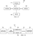
- FIG. 17 illustrates a block diagram of an embodiment processing system 600 for performing methods described herein, which may be installed in a host device.
- the processing system 600 includes a processor 604 , a memory 606 , and interfaces 610 - 614 , which may (or may not) be arranged as shown in FIG. 17 .
- the processor 604 may be any component or collection of components adapted to perform computations and/or other processing related tasks
- the memory 606 may be any component or collection of components adapted to store programming and/or instructions for execution by the processor 604 .
- the memory 606 includes a non-transitory computer readable medium.
- the interfaces 610 , 612 , 614 may be any component or collection of components that allow the processing system 600 to communicate with other devices/components and/or a user.
- one or more of the interfaces 610 , 612 , 614 may be adapted to communicate data, control, or management messages from the processor 604 to applications installed on the host device and/or a remote device.
- one or more of the interfaces 610 , 612 , 614 may be adapted to allow a user or user device (e.g., personal computer (PC), etc.) to interact/communicate with the processing system 600 .
- the processing system 600 may include additional components not depicted in FIG. 17 , such as long term storage (e.g., non-volatile memory, etc.).
- the processing system 600 is included in a network device that is accessing, or part otherwise of, a telecommunications network.
- the processing system 600 is in a network-side device in a wireless or wireline telecommunications network, such as a base station, a relay station, a scheduler, a controller, a gateway, a router, an applications server, or any other device in the telecommunications network.
- the processing system 600 is in a user-side device accessing a wireless or wireline telecommunications network, such as a mobile station, a user equipment (UE), a personal computer (PC), a tablet, a wearable communications device (e.g., a smartwatch, etc.), or any other device adapted to access a telecommunications network.
- a wireless or wireline telecommunications network such as a mobile station, a user equipment (UE), a personal computer (PC), a tablet, a wearable communications device (e.g., a smartwatch, etc.), or any other device adapted to access a telecommunications network.
- one or more of the interfaces 610 , 612 , 614 connects the processing system 600 to a transceiver adapted to transmit and receive signaling over the telecommunications network.
- FIG. 18 illustrates a block diagram of a transceiver 700 adapted to transmit and receive signaling over a telecommunications network.
- the transceiver 700 may be installed in a host device. As shown, the transceiver 700 comprises a network-side interface 702 , a coupler 704 , a transmitter 706 , a receiver 708 , a signal processor 710 , and a device-side interface 712 .
- the network-side interface 702 may include any component or collection of components adapted to transmit or receive signaling over a wireless or wireline telecommunications network.
- the coupler 704 may include any component or collection of components adapted to facilitate bi-directional communication over the network-side interface 702 .
- the transmitter 706 may include any component or collection of components (e.g., up-converter, power amplifier, etc.) adapted to convert a baseband signal into a modulated carrier signal suitable for transmission over the network-side interface 702 .
- the receiver 708 may include any component or collection of components (e.g., down-converter, low noise amplifier, etc.) adapted to convert a carrier signal received over the network-side interface 702 into a baseband signal.
- the signal processor 710 may include any component or collection of components adapted to convert a baseband signal into a data signal suitable for communication over the device-side interface(s) 712 , or vice-versa.
- the device-side interface(s) 712 may include any component or collection of components adapted to communicate data-signals between the signal processor 710 and components within the host device (e.g., the processing system 600 , local area network (LAN) ports, etc.).
- the transceiver 700 may transmit and receive signaling over any type of communications medium.
- the transceiver 700 transmits and receives signaling over a wireless medium.
- the transceiver 700 may be a wireless transceiver adapted to communicate in accordance with a wireless telecommunications protocol, such as a cellular protocol (e.g., long-term evolution (LTE), etc.), a wireless local area network (WLAN) protocol (e.g., Wi-Fi, etc.), or any other type of wireless protocol (e.g., Bluetooth, near field communication (NFC), etc.).
- a wireless telecommunications protocol such as a cellular protocol (e.g., long-term evolution (LTE), etc.), a wireless local area network (WLAN) protocol (e.g., Wi-Fi, etc.), or any other type of wireless protocol (e.g., Bluetooth, near field communication (NFC), etc.).
- the network-side interface 702 comprises one or more antenna/radiating elements.
- the network-side interface 702 may include a single antenna, multiple separate antennas, or a multi-antenna array configured for multi-layer communication, e.g., single input multiple output (SIMO), multiple input single output (MISO), multiple input multiple output (MIMO), etc.
- the transceiver 700 transmits and receives signaling over a wireline medium, e.g., twisted-pair cable, coaxial cable, optical fiber, etc.
- Specific processing systems and/or transceivers may utilize all of the components shown, or only a subset of the components, and levels of integration may vary from device to device.
Landscapes
- Engineering & Computer Science (AREA)
- Computer Networks & Wireless Communication (AREA)
- Signal Processing (AREA)
- Mobile Radio Communication Systems (AREA)
Abstract
Description
T=T S +T CP +T G,
where Ts is the actual sequence time, TCP is the cyclic prefix time, and TG is the guard time at the end of the sequence. The cyclic prefix time and guard time are both more than the maximum delay of the channel plus the maximum timing mismatch. During the guard time, all UEs remain silent. The Zadoff Chu number, NZC, is a prime number slightly less than BW*Ts. Each of the primary sequence time set (TS, TCP, TG) may be normalized by the sequence length, e.g.:
The root of the sequence for different users is RU, where some users may have the same root. The cyclic shift for each sequence is CSu. UEs with the same root have a CS difference larger than the bandwidth times the maximum allowed total channel delay and timing mismatch ΔT. A UE sequence is defined by:
for n=0, . . . , NZC−1. The sequence is mapped to the TS. In one example, with orthogonal frequency division multiplexing (OFDM) based transmission, the carrier spacing is defined by 1/Ts. The cyclic prefix uses the last NCP samples to the beginning of the sequence.
The above is derived due to the fact that the total possible roots are given by:
N ZC−1≅BW×T s,
and the total possible cyclic shifts are approximately given by:
For example, in parameters similar to those used in LTE, when NZC=839 and ΔT=5 μs, equivalent to almost 5 chips, a total channel dispersion and mismatch of 1.5 km, and a maximum pool size of 140,000. The pool size increases linearly with bandwidth and quadratically with time increase. The timing of the UEs may be improved by reducing ΔT, which may not be less than the channel dispersion time for already connected and time adjusted UEs.
When NZC is 839, the correlation between the different roots is 0.0345.
The total interference measured for a sequence or for its shifted versions is a function of the actual number of UEs sending TCs, the transmitted power, and the channel between the UEs and the network nodes measuring the TC signals. When the power received by the UE in the vicinity of radius r of the network node is significant, and the overall hypercell size has a radius R, the Poisson distributed random variable of significant interference to the UE is a function of the parameter:
When the parameter is large and the received power from significant interferences and the target signal are constant, the signal-to-noise ratio (SNR) of the measured delay for the target user is given by:
where Ptap is the percentage of power received from that UE in a given tap. The SNR varies based on the tap, and is around 60% to around 70% for the most powerful taps, and smaller for less powerful taps. This Ptap is determined by measuring only one sample using one correlation of the signal and not using any repetition or coding, unless joint decoding is performed at multiple network nodes. A high SNR, for example above about 10 dB, maintains a reasonable miss rate or false alarm rate. The maximum significant interference within radius r is limited, with relatively few UEs interfering in the vicinity for the resources.
where Nd is the minimum allowed shift, which is determined by the maximum delay. The sequence pool is selected, and the maximum number of allowed sequences in the same sequence set, Nseq, is determined. Also, the minimum allowed shift, and the hence the number of sequences from the same root, Nsr, are determined. Additionally, the number of required roots is determined from:
| TABLE 1 | |||||
| PRACH | System | ||||
| Configuration | Preamble | Frame | |||
| Index | Format | Number | Subframe Number | ||
| 0 | 0 | Even | 1 | ||
| 1 | 0 | Even | 4 | ||
| 2 | 0 | Even | 7 | ||
| 3 | 0 | Any | 1 | ||
| 4 | 0 | Any | 4 | ||
| 5 | 0 | Any | 7 | ||
| 6 | 0 | Any | 1, 6 | ||
| 7 | 0 | Any | 2, 7 | ||
| 8 | 0 | Any | 3, 8 | ||
| 9 | 0 | Any | 1, 4, 7 | ||
| 10 | 0 | Any | 2, 5, 8 | ||
| 11 | 0 | Any | 3, 6, 9 | ||
| 12 | 0 | Any | 0, 2, 4, 6, 8 | ||
| 13 | 0 | Any | 1, 3, 5, 7, 9 | ||
| 14 | 0 | Any | 0, 1, 2, 3, 4, 5, 6, 7, 8, 9 | ||
| 15 | 0 | Even | 9 | ||
| 16 | 1 | Even | 1 | ||
| 17 | 1 | Even | 4 | ||
| 18 | 1 | Even | 7 | ||
| 19 | 1 | Any | 1 | ||
| 20 | 1 | Any | 4 | ||
| 21 | 1 | Any | 7 | ||
| 22 | 1 | Any | 1, 6 | ||
| 23 | 1 | Any | 2, 7 | ||
| 24 | 1 | Any | 3, 8 | ||
| 25 | 1 | Any | 1, 4, 7 | ||
| 26 | 1 | Any | 2, 5, 8 | ||
| 27 | 1 | Any | 3, 6, 9 | ||
| 28 | 1 | Any | 0, 2, 4, 6, 8 | ||
| 29 | 1 | Any | 1, 3, 5, 7, 9 | ||
| 30 | N/A | N/A | N/A | ||
| 31 | 1 | Even | 9 | ||
| 32 | 2 | Even | 1 | ||
| 33 | 2 | Even | 4 | ||
| 34 | 2 | Even | 7 | ||
| 35 | 2 | Any | 1 | ||
| 36 | 2 | Any | 4 | ||
| 37 | 2 | Any | 7 | ||
| 38 | 2 | Any | 1, 6 | ||
| 39 | 2 | Any | 2, 7 | ||
| 40 | 2 | Any | 3, 8 | ||
| 41 | 2 | Any | 1, 4, 7 | ||
| 42 | 2 | Any | 2, 5, 8 | ||
| 43 | 2 | Any | 3, 6, 9 | ||
| 44 | 2 | Any | 0, 2, 4, 6, 8 | ||
| 45 | 2 | Any | 1, 3, 5, 7, 9 | ||
| 46 | N/A | N/A | N/A | ||
| 47 | 2 | Even | 9 | ||
| 48 | 3 | Even | 1 | ||
| 49 | 3 | Even | 4 | ||
| 50 | 3 | Even | 7 | ||
| 51 | 3 | Any | 1 | ||
| 52 | 3 | Any | 4 | ||
| 53 | 3 | Any | 7 | ||
| 54 | 3 | Any | 1, 6 | ||
| 55 | 3 | Any | 2, 7 | ||
| 56 | 3 | Any | 3, 8 | ||
| 57 | 3 | Any | 1, 4, 7 | ||
| 58 | 3 | Any | 2, 5, 8 | ||
| 59 | 3 | Any | 3, 6, 9 | ||
| 60 | N/A | N/A | N/A | ||
| 61 | N/A | N/A | N/A | ||
| 62 | N/A | N/A | N/A | ||
| 63 | 3 | 3 | 9 | ||
Claims (27)
Priority Applications (1)
| Application Number | Priority Date | Filing Date | Title |
|---|---|---|---|
| US16/735,120 US11368998B2 (en) | 2015-04-01 | 2020-01-06 | System and method for a tracking channel |
Applications Claiming Priority (4)
| Application Number | Priority Date | Filing Date | Title |
|---|---|---|---|
| US201562141483P | 2015-04-01 | 2015-04-01 | |
| US201562213444P | 2015-09-02 | 2015-09-02 | |
| US15/009,626 US10531512B2 (en) | 2015-04-01 | 2016-01-28 | System and method for a tracking channel |
| US16/735,120 US11368998B2 (en) | 2015-04-01 | 2020-01-06 | System and method for a tracking channel |
Related Parent Applications (1)
| Application Number | Title | Priority Date | Filing Date |
|---|---|---|---|
| US15/009,626 Continuation US10531512B2 (en) | 2015-04-01 | 2016-01-28 | System and method for a tracking channel |
Publications (2)
| Publication Number | Publication Date |
|---|---|
| US20200146092A1 US20200146092A1 (en) | 2020-05-07 |
| US11368998B2 true US11368998B2 (en) | 2022-06-21 |
Family
ID=57003937
Family Applications (2)
| Application Number | Title | Priority Date | Filing Date |
|---|---|---|---|
| US15/009,626 Active US10531512B2 (en) | 2015-04-01 | 2016-01-28 | System and method for a tracking channel |
| US16/735,120 Active US11368998B2 (en) | 2015-04-01 | 2020-01-06 | System and method for a tracking channel |
Family Applications Before (1)
| Application Number | Title | Priority Date | Filing Date |
|---|---|---|---|
| US15/009,626 Active US10531512B2 (en) | 2015-04-01 | 2016-01-28 | System and method for a tracking channel |
Country Status (7)
| Country | Link |
|---|---|
| US (2) | US10531512B2 (en) |
| EP (2) | EP3269169B1 (en) |
| JP (1) | JP6541796B2 (en) |
| KR (1) | KR102048229B1 (en) |
| CN (2) | CN111511039B (en) |
| CA (1) | CA2981376C (en) |
| WO (1) | WO2016155649A1 (en) |
Families Citing this family (22)
| Publication number | Priority date | Publication date | Assignee | Title |
|---|---|---|---|---|
| WO2012030319A2 (en) | 2009-06-26 | 2012-03-08 | Hypres, Inc. | System and method for controlling combined radio signals |
| US9426663B2 (en) | 2013-06-26 | 2016-08-23 | Cable Television Laboratories, Inc. | Capacity sharing between wireless systems |
| US9730196B2 (en) | 2014-07-29 | 2017-08-08 | Cable Television Laboratories, Inc. | LTE control channel reservation in RF bands with competing communication systems |
| KR20160126296A (en) * | 2015-04-23 | 2016-11-02 | 에스케이텔레콤 주식회사 | Apparatus for road guide and control method thereof |
| CN107534896B (en) * | 2015-05-14 | 2021-09-14 | 有线电视实验室公司 | Hybrid automatic repeat request (HARQ) in listen-before-talk systems |
| US10735166B2 (en) | 2015-05-29 | 2020-08-04 | Huawei Technologies Co., Ltd. | System and method of UE-centric radio access procedure |
| US10356608B2 (en) | 2016-02-18 | 2019-07-16 | Huawei Technologies Co., Ltd. | System and method of user equipment state configurations |
| CN107205271B (en) | 2016-03-16 | 2020-04-28 | 华为技术有限公司 | Network out-of-step state processing method, network access method and device |
| US10652851B2 (en) | 2016-11-03 | 2020-05-12 | Huawei Technologies Co., Ltd. | Uplink-based user equipment tracking for connected inactive state |
| CN108377491B (en) * | 2016-11-11 | 2021-06-22 | 华为技术有限公司 | Response method and device for uplink signal |
| US11116006B2 (en) * | 2016-12-16 | 2021-09-07 | Qualcomm Incorporated | Uplink transmission parameter selection for random access initial message transmission and retransmission |
| US11184852B2 (en) * | 2017-03-20 | 2021-11-23 | Sony Group Corporation | Wake-up signal with reconfigurable sequence design |
| WO2019000366A1 (en) * | 2017-06-30 | 2019-01-03 | Qualcomm Incorporated | Selection between code types for encoding information bits |
| US11310741B2 (en) * | 2017-08-18 | 2022-04-19 | Sony Group Corporation | Wake-up signal related monitoring of wireless data communication |
| CN111770561B (en) * | 2017-08-28 | 2024-12-13 | 息思维国际股份有限公司 | A method and device for saving power in a user or base station |
| US11153142B2 (en) * | 2017-11-30 | 2021-10-19 | Intel Corporation | Methods and devices for narrowband communications |
| KR102157898B1 (en) * | 2018-04-27 | 2020-09-21 | 한양대학교 산학협력단 | Apparatus and method for configuring signal for positioning of mobile communication ue |
| CN113302860B (en) * | 2019-01-17 | 2023-05-09 | 中兴通讯股份有限公司 | Contention-based payload transmission using differential encoding |
| US11269595B2 (en) * | 2019-11-01 | 2022-03-08 | EMC IP Holding Company LLC | Encoding and evaluating multisets using prime numbers |
| CN111901785B (en) * | 2020-04-09 | 2025-12-23 | 中兴通讯股份有限公司 | Energy-saving configuration methods, energy-saving methods, devices, communication nodes and storage media |
| US11678279B2 (en) * | 2020-06-04 | 2023-06-13 | Qualcomm Incorporated | Timing accuracy for reference signal transmission during user equipment (UE) power saving state |
| CN114236478B (en) * | 2021-11-16 | 2025-12-12 | 中国航空工业集团公司雷华电子技术研究所 | An Optimization Method for Single-Site Interference Resources |
Citations (74)
| Publication number | Priority date | Publication date | Assignee | Title |
|---|---|---|---|---|
| WO2003081820A1 (en) | 2002-03-27 | 2003-10-02 | Da Tang Mobile Communications Equipment Co., Ltd. | Method of mobile communication system with smart antenna |
| US20060091206A1 (en) | 2004-10-29 | 2006-05-04 | United Parcel Service Of America, Inc. | Systems and methods for tracking items using wirelessly-enabled devices |
| CN101090281A (en) | 2007-06-19 | 2007-12-19 | 中兴通讯股份有限公司 | Uplink random access leading sequential selection method |
| US20080188219A1 (en) * | 2007-02-06 | 2008-08-07 | Lg Electronics Inc. | Use of dedicated rach signatures |
| US20090088134A1 (en) * | 2005-08-24 | 2009-04-02 | Ntt Docomo, Inc. | Mobile station, radio access network apparatus mobility switching station, mobile communication system, and communication service access method |
| US20090121940A1 (en) | 2007-11-13 | 2009-05-14 | Jonathan Ladd | System for determining position over a network |
| US20090248164A1 (en) | 2006-01-26 | 2009-10-01 | Spinal Generations, Llc | Interbody cage system |
| CN101686469A (en) | 2008-09-25 | 2010-03-31 | 中兴通讯股份有限公司 | Method for realizing downstream data beam formation and system thereof |
| US20100272035A1 (en) | 2007-10-29 | 2010-10-28 | Sung Jun Park | Method of performing random access procedure in wireless communication system |
| CN101883423A (en) | 2009-05-07 | 2010-11-10 | 大唐移动通信设备有限公司 | Method, system and device for determining position information of terminal |
| US20110044269A1 (en) | 2009-07-29 | 2011-02-24 | Qualcomm Incorporated | Methods and apparatus for blind interference decrease/cancellation techniques |
| US20110111751A1 (en) | 2005-12-15 | 2011-05-12 | Invisitrack, Inc. | Multi-path mitigation in rangefinding and tracking objects using reduced attenuation rf technology |
| US20110116436A1 (en) | 2009-05-08 | 2011-05-19 | Qualcomm Incorporated | Transmission and reception of a reference signal supporting positioning in a wireless communication network |
| US20110237266A1 (en) * | 2010-03-26 | 2011-09-29 | Research In Motion Limited | Sounding Reference Signal Transmission During Discontinuous Reception |
| US20120014343A1 (en) * | 2008-03-20 | 2012-01-19 | Research In Motion Limited | System and method for uplink timing synchronization in conjunction with discontinuous reception |
| CN102355680A (en) | 2011-09-27 | 2012-02-15 | 华为技术有限公司 | Method and device for opening base station |
| US20120106489A1 (en) | 2009-06-19 | 2012-05-03 | Satoshi Konishi | Reference Signal Transmission Scheduling Device and Reference Signal Transmission Scheduling Method |
| JP2012110058A (en) | 2012-03-05 | 2012-06-07 | Sharp Corp | Radio communication system, mobile station device, random access method, and integrated circuit |
| US20120163320A1 (en) | 2009-08-04 | 2012-06-28 | Sharp Kabushiki Kaisha | Wireless communication system, mobile station apparatus and base station apparatus |
| US20120170497A1 (en) * | 2011-01-04 | 2012-07-05 | HT mMobile Inc. | Method for reporting srs in discontinuous reception and wireless communication system thereof |
| US20120202558A1 (en) * | 2011-02-07 | 2012-08-09 | Telefonaktiebolaget L M Ericsson (Publ) | Uplink Selection Using Sounding Reference Signals in Radiocommunication Systems |
| US8249004B2 (en) * | 2008-03-14 | 2012-08-21 | Interdigital Patent Holdings, Inc. | Coordinated uplink transmission in LTE DRX operations for a wireless transmit receive unit |
| US8265682B2 (en) * | 2008-03-18 | 2012-09-11 | Texas Instruments Incorporated | Scheduling request usage in DRX mode in wireless networks |
| WO2012137033A1 (en) * | 2011-04-08 | 2012-10-11 | Alcatel Lucent | A method of state control of non-access stratum in wireless network |
| CN102823315A (en) | 2010-03-29 | 2012-12-12 | 夏普株式会社 | Wireless communication system, mobile station device, base station device, random access method, and integrated circuit |
| US20130039304A1 (en) | 2010-02-11 | 2013-02-14 | China Academy Of Telecommunications Technology | Method for sending sounding reference signals (srs), trigger method and device thereof |
| US20130058306A1 (en) | 2010-05-14 | 2013-03-07 | Lg Electronics Inc. | Method and apparatus for transmitting aperiodic sounding reference signal in wireless communication system |
| KR20130028397A (en) | 2011-09-09 | 2013-03-19 | 삼성전자주식회사 | Apparatus and method for synchronizing and obtaining system information in wireless communication system |
| US8401031B2 (en) * | 2007-02-06 | 2013-03-19 | Lg Electronics Inc. | Method of performing random access procedure in wireless communication system |
| US20130077569A1 (en) | 2011-09-22 | 2013-03-28 | Samsung Electronics Co. Ltd. | Apparatus and method for uplink transmission in wireless communication systems |
| US20130077577A1 (en) | 2010-04-30 | 2013-03-28 | Ntt Docomo, Inc. | Mobile communication method and mobile station |
| WO2013061430A1 (en) | 2011-10-26 | 2013-05-02 | 富士通株式会社 | Base station device, mobile station device, and random access method |
| US20130170453A1 (en) * | 2007-08-07 | 2013-07-04 | Samsung Electronics Co., Ltd. | Method and apparatus for performing random access procedure in a mobile communication system |
| US20130182674A1 (en) | 2010-08-16 | 2013-07-18 | Nokia Siemens Networks Oy | Transmission of Reference Signals |
| US20130223362A1 (en) | 2012-02-15 | 2013-08-29 | Frank Alfano | Uplink resource access in wireless networks |
| US20130244709A1 (en) | 2012-03-16 | 2013-09-19 | Alexei Davydov | Interference mitigation in the context of heterogeneous networks with coordinated transmission points with a common transmission point identity |
| US20130315152A1 (en) | 2012-05-24 | 2013-11-28 | Nokia Siemens Networks Oy | Using Unique Preambles for D2D Communications in LTE |
| US8599819B2 (en) | 2007-06-19 | 2013-12-03 | Lg Electronics Inc. | Method of transmitting sounding reference signal |
| WO2013177992A1 (en) * | 2012-05-29 | 2013-12-05 | 中兴通讯股份有限公司 | Method and system for sending control signaling in power save mode |
| US20130322375A1 (en) | 2012-05-31 | 2013-12-05 | Samsung Electronics Co., Ltd | Apparatus and method of cooperating with multiple base stations in wireless communication system |
| CN103535096A (en) | 2011-07-15 | 2014-01-22 | 富士通株式会社 | Sounding reference symbol sending method, base station, and user equipment |
| JP2014057357A (en) | 2013-11-18 | 2014-03-27 | Fujitsu Ltd | Radio communication device, radio communication system, and radio communication method |
| US20140155061A1 (en) | 2012-12-05 | 2014-06-05 | Broadcom Corporation | Enhanced Higher Priority Public Land Mobile Network (HPPLMN) Search |
| US20140198701A1 (en) * | 2011-08-12 | 2014-07-17 | Telefonaktiebolaget L M Ericsson (Publ) | Deciding Whether to Send Uplink Control Signaling Based on the Active Time Status of a User Equipment Configured with Discontinuous Reception (DRX) |
| US8797986B2 (en) | 2009-10-30 | 2014-08-05 | Panasonic Intellectual Property Corporation Of America | Wireless communication apparatus and reference signal generating method |
| US20140376401A1 (en) * | 2013-06-21 | 2014-12-25 | Qualcomm Incorporated | Averaging buffer occupancy to improve performance at a user equipment (ue) |
| US20140376482A1 (en) * | 2012-01-30 | 2014-12-25 | Samsung Electronics Co., Ltd | Method and device for transmitting sounding reference signal in cooperative communication system |
| US20150003263A1 (en) | 2013-06-28 | 2015-01-01 | Futurewei Technologies, Inc. | System and Method for Network Uplink Measurement Based Operation Using UE Centric Sounding |
| US20150011240A1 (en) | 2012-02-20 | 2015-01-08 | Huawei Technologies Co., Ltd. | Network positioning method and related equipment |
| WO2015013976A1 (en) | 2013-08-02 | 2015-02-05 | 华为技术有限公司 | Method and device for random access in idle state |
| US20150063128A1 (en) | 2013-08-27 | 2015-03-05 | Nokia Corporation | Method, apparatus, and computer program product for wireless signaling |
| WO2015178566A1 (en) * | 2014-05-18 | 2015-11-26 | Lg Electronics Inc. | Method and apparatus for transmitting uplink data in a wireless communication system |
| US20160105910A1 (en) | 2014-10-09 | 2016-04-14 | Qualcomm Incorporated | Uplink synchronization without preamble in sc-fdma |
| US9398584B2 (en) | 2009-04-20 | 2016-07-19 | China Academy Of Telecommunications Technology | Method and apparatus of configuring sounding reference signal for coordinated multi-point transmission |
| US20160270082A1 (en) * | 2015-03-13 | 2016-09-15 | Qualcomm Incorporated | System and method for mobility tracking of user equipment |
| US20160323887A1 (en) * | 2015-05-01 | 2016-11-03 | Qualcomm Incorporated | Low latency uplink power control |
| US20160352403A1 (en) | 2014-02-07 | 2016-12-01 | Ntt Docomo, Inc. | User apparatus, base station, and communication method |
| US9544776B2 (en) | 2008-03-25 | 2017-01-10 | Qualcomm Incorporated | Transmission and reception of dedicated reference signals |
| CN106358310A (en) * | 2016-08-29 | 2017-01-25 | 吉林大学 | DRX (discontinuous reception) period based optimization method for uplink dynamic scheduling of VoLTE (voice over long term evolution) business |
| US20170034781A1 (en) * | 2015-07-30 | 2017-02-02 | Samsung Electronics Co., Ltd. | Method of enhancing uplink transmission handling in a discontinuous reception (drx) mode of a user equipment |
| US9603091B2 (en) | 2012-04-24 | 2017-03-21 | Telefonaktiebolaget L M Ericsson | Reducing periodic reporting in discontinuous receive (DRX) mode |
| US9794101B2 (en) | 2009-07-30 | 2017-10-17 | China Academy Of Telecommunications Technology | Method, device and system for transmitting sounding reference signals |
| US10033547B2 (en) * | 2009-06-10 | 2018-07-24 | Huawei Technologies Co., Ltd. | Method, device, and system for controlling tunnel identifier allocation |
| WO2019085607A1 (en) * | 2017-11-03 | 2019-05-09 | 中国移动通信有限公司研究院 | Method for uplink transmission in drx configuration, device, equipment, and storage medium |
| EP3491870A1 (en) * | 2016-08-15 | 2019-06-05 | Huawei Technologies Co., Ltd. | Advance scheduling for discontinuous transmission and reception using uplink beacons |
| CN110557806A (en) * | 2018-05-31 | 2019-12-10 | 电信科学技术研究院有限公司 | Data transmission method, terminal equipment and network equipment |
| KR102065698B1 (en) * | 2012-07-09 | 2020-02-11 | 엘지전자 주식회사 | Method and apparatus for controlling uplink transmission on discontinuous reception operation in wireless communication system |
| US10652862B2 (en) * | 2012-05-10 | 2020-05-12 | Samsung Electronics Co., Ltd | Method and system for connectionless transmission during uplink and downlink of data packets |
| US10652851B2 (en) * | 2016-11-03 | 2020-05-12 | Huawei Technologies Co., Ltd. | Uplink-based user equipment tracking for connected inactive state |
| WO2020102685A1 (en) * | 2018-11-16 | 2020-05-22 | Google Llc | Uplink communication in an inactive state in a celluar network |
| US20200214041A1 (en) * | 2016-06-07 | 2020-07-02 | Nokia Technologies Oy | Multi-connectivity of terminal device |
| US20210227585A1 (en) * | 2020-01-16 | 2021-07-22 | FG Innovation Company Limited | Method of random access procedure and related device |
| US20210243812A1 (en) * | 2020-02-03 | 2021-08-05 | Samsung Electronics Co., Ltd. | Method and apparatus for performing communication in wireless communication system |
| US20220030544A1 (en) * | 2020-07-27 | 2022-01-27 | Samsung Electronics Co., Ltd. | Positioning in rrc idle and inactive states |
Family Cites Families (12)
| Publication number | Priority date | Publication date | Assignee | Title |
|---|---|---|---|---|
| US8218526B2 (en) * | 2007-04-30 | 2012-07-10 | Texas Instruments Incorporated | Uplink synchronization maintenance principles in wireless networks |
| US8477811B2 (en) * | 2008-02-02 | 2013-07-02 | Qualcomm Incorporated | Radio access network (RAN) level keep alive signaling |
| US20090247164A1 (en) * | 2008-03-28 | 2009-10-01 | Qualcomm Incorporated | Handoff algorithm and architecture for mobile system |
| CN102685862A (en) * | 2009-03-12 | 2012-09-19 | 华为技术有限公司 | Power saving activation method and device |
| CN102246573B (en) * | 2009-03-30 | 2014-07-30 | 华为技术有限公司 | Random access method, enodeb and terminal equipment |
| EP2461634B1 (en) * | 2009-07-28 | 2016-04-06 | Fujitsu Limited | Communication system, base station, mobile terminal, and communication method |
| US9401784B2 (en) * | 2009-10-21 | 2016-07-26 | Qualcomm Incorporated | Time and frequency acquisition and tracking for OFDMA wireless systems |
| CN102098655B (en) * | 2009-12-11 | 2013-12-04 | 中兴通讯股份有限公司 | Method and system for controlling activation of ISR (Idle mode Signaling Reduction) and UE (user equipment) |
| US8917593B2 (en) * | 2010-03-18 | 2014-12-23 | Qualcomm Incorporated | Random access design in a multiple component carrier communication network |
| US9398494B2 (en) * | 2011-07-04 | 2016-07-19 | Broadcom Corporation | Methods, devices and computer program products providing for improved random access in a local area network environment |
| EP2783539B1 (en) * | 2011-11-22 | 2016-03-02 | SCA IPLA Holdings Inc. | System and method for paging off-line state terminals |
| US9451641B2 (en) * | 2012-03-30 | 2016-09-20 | Qualcomm Incorporated | Methods and apparatus for improving data service availability |
-
2016
- 2016-01-28 US US15/009,626 patent/US10531512B2/en active Active
- 2016-03-31 EP EP16771404.7A patent/EP3269169B1/en active Active
- 2016-03-31 EP EP20152441.0A patent/EP3657893B1/en active Active
- 2016-03-31 KR KR1020177030722A patent/KR102048229B1/en active Active
- 2016-03-31 CN CN202010182314.3A patent/CN111511039B/en active Active
- 2016-03-31 CA CA2981376A patent/CA2981376C/en active Active
- 2016-03-31 JP JP2017551145A patent/JP6541796B2/en active Active
- 2016-03-31 WO PCT/CN2016/078103 patent/WO2016155649A1/en not_active Ceased
- 2016-03-31 CN CN201680021001.1A patent/CN107534871B/en active Active
-
2020
- 2020-01-06 US US16/735,120 patent/US11368998B2/en active Active
Patent Citations (121)
| Publication number | Priority date | Publication date | Assignee | Title |
|---|---|---|---|---|
| US20050152303A1 (en) | 2002-03-27 | 2005-07-14 | Shihe Li | Method of mobile communication system with smart antenna |
| WO2003081820A1 (en) | 2002-03-27 | 2003-10-02 | Da Tang Mobile Communications Equipment Co., Ltd. | Method of mobile communication system with smart antenna |
| US20060091206A1 (en) | 2004-10-29 | 2006-05-04 | United Parcel Service Of America, Inc. | Systems and methods for tracking items using wirelessly-enabled devices |
| US20090088134A1 (en) * | 2005-08-24 | 2009-04-02 | Ntt Docomo, Inc. | Mobile station, radio access network apparatus mobility switching station, mobile communication system, and communication service access method |
| US20110111751A1 (en) | 2005-12-15 | 2011-05-12 | Invisitrack, Inc. | Multi-path mitigation in rangefinding and tracking objects using reduced attenuation rf technology |
| US20090248164A1 (en) | 2006-01-26 | 2009-10-01 | Spinal Generations, Llc | Interbody cage system |
| US20080188219A1 (en) * | 2007-02-06 | 2008-08-07 | Lg Electronics Inc. | Use of dedicated rach signatures |
| US8401031B2 (en) * | 2007-02-06 | 2013-03-19 | Lg Electronics Inc. | Method of performing random access procedure in wireless communication system |
| CN101090281A (en) | 2007-06-19 | 2007-12-19 | 中兴通讯股份有限公司 | Uplink random access leading sequential selection method |
| US8599819B2 (en) | 2007-06-19 | 2013-12-03 | Lg Electronics Inc. | Method of transmitting sounding reference signal |
| US20130322387A1 (en) * | 2007-08-07 | 2013-12-05 | Samsung Electronics Co., Ltd. | Method and apparatus for performing random access procedure in a mobile communication system |
| US20130170453A1 (en) * | 2007-08-07 | 2013-07-04 | Samsung Electronics Co., Ltd. | Method and apparatus for performing random access procedure in a mobile communication system |
| US20100272035A1 (en) | 2007-10-29 | 2010-10-28 | Sung Jun Park | Method of performing random access procedure in wireless communication system |
| CN101855566A (en) | 2007-11-13 | 2010-10-06 | 诺瓦特公司 | System for determining location via network |
| US20090121940A1 (en) | 2007-11-13 | 2009-05-14 | Jonathan Ladd | System for determining position over a network |
| US8249004B2 (en) * | 2008-03-14 | 2012-08-21 | Interdigital Patent Holdings, Inc. | Coordinated uplink transmission in LTE DRX operations for a wireless transmit receive unit |
| US8265682B2 (en) * | 2008-03-18 | 2012-09-11 | Texas Instruments Incorporated | Scheduling request usage in DRX mode in wireless networks |
| US8238837B2 (en) * | 2008-03-20 | 2012-08-07 | Research In Motion Limited | System and method for uplink timing synchronization in conjunction with discontinuous reception |
| US20120014343A1 (en) * | 2008-03-20 | 2012-01-19 | Research In Motion Limited | System and method for uplink timing synchronization in conjunction with discontinuous reception |
| US9544776B2 (en) | 2008-03-25 | 2017-01-10 | Qualcomm Incorporated | Transmission and reception of dedicated reference signals |
| CN101686469A (en) | 2008-09-25 | 2010-03-31 | 中兴通讯股份有限公司 | Method for realizing downstream data beam formation and system thereof |
| US9398584B2 (en) | 2009-04-20 | 2016-07-19 | China Academy Of Telecommunications Technology | Method and apparatus of configuring sounding reference signal for coordinated multi-point transmission |
| US20120134288A1 (en) | 2009-05-07 | 2012-05-31 | China Academy Of Telecommunications Technology | Method, system and device for determining position information of user equipment |
| CN101883423A (en) | 2009-05-07 | 2010-11-10 | 大唐移动通信设备有限公司 | Method, system and device for determining position information of terminal |
| JP2012526425A (en) | 2009-05-07 | 2012-10-25 | 電信科学技術研究院 | Method, system and apparatus for determining location information of user terminal |
| US20110116436A1 (en) | 2009-05-08 | 2011-05-19 | Qualcomm Incorporated | Transmission and reception of a reference signal supporting positioning in a wireless communication network |
| US8964621B2 (en) | 2009-05-08 | 2015-02-24 | Qualcomm Incorporated | Transmission and reception of a reference signal supporting positioning in a wireless communication network |
| US10033547B2 (en) * | 2009-06-10 | 2018-07-24 | Huawei Technologies Co., Ltd. | Method, device, and system for controlling tunnel identifier allocation |
| US20120106489A1 (en) | 2009-06-19 | 2012-05-03 | Satoshi Konishi | Reference Signal Transmission Scheduling Device and Reference Signal Transmission Scheduling Method |
| US20110044269A1 (en) | 2009-07-29 | 2011-02-24 | Qualcomm Incorporated | Methods and apparatus for blind interference decrease/cancellation techniques |
| US9794101B2 (en) | 2009-07-30 | 2017-10-17 | China Academy Of Telecommunications Technology | Method, device and system for transmitting sounding reference signals |
| US20120163320A1 (en) | 2009-08-04 | 2012-06-28 | Sharp Kabushiki Kaisha | Wireless communication system, mobile station apparatus and base station apparatus |
| US8797986B2 (en) | 2009-10-30 | 2014-08-05 | Panasonic Intellectual Property Corporation Of America | Wireless communication apparatus and reference signal generating method |
| US20130039304A1 (en) | 2010-02-11 | 2013-02-14 | China Academy Of Telecommunications Technology | Method for sending sounding reference signals (srs), trigger method and device thereof |
| US20110237266A1 (en) * | 2010-03-26 | 2011-09-29 | Research In Motion Limited | Sounding Reference Signal Transmission During Discontinuous Reception |
| CN102823315A (en) | 2010-03-29 | 2012-12-12 | 夏普株式会社 | Wireless communication system, mobile station device, base station device, random access method, and integrated circuit |
| US20130136073A1 (en) | 2010-03-29 | 2013-05-30 | Sharp Kabushiki Kaisha | Wireless communication system, mobile station apparatus, base station apparatus, randome access method, and itegrated circuit |
| US8817721B2 (en) | 2010-04-30 | 2014-08-26 | Ntt Docomo, Inc. | Mobile communication method and mobile station |
| US20130077577A1 (en) | 2010-04-30 | 2013-03-28 | Ntt Docomo, Inc. | Mobile communication method and mobile station |
| US20130058306A1 (en) | 2010-05-14 | 2013-03-07 | Lg Electronics Inc. | Method and apparatus for transmitting aperiodic sounding reference signal in wireless communication system |
| US20130182674A1 (en) | 2010-08-16 | 2013-07-18 | Nokia Siemens Networks Oy | Transmission of Reference Signals |
| US20160142190A1 (en) | 2010-08-16 | 2016-05-19 | Nokia Solutions and Network OY | Transmission of Reference Signals |
| US20120170497A1 (en) * | 2011-01-04 | 2012-07-05 | HT mMobile Inc. | Method for reporting srs in discontinuous reception and wireless communication system thereof |
| US20120202558A1 (en) * | 2011-02-07 | 2012-08-09 | Telefonaktiebolaget L M Ericsson (Publ) | Uplink Selection Using Sounding Reference Signals in Radiocommunication Systems |
| CN102740420A (en) * | 2011-04-08 | 2012-10-17 | 上海贝尔股份有限公司 | State control method for non-access stratum of wireless network |
| CN102740420B (en) * | 2011-04-08 | 2015-03-11 | 上海贝尔股份有限公司 | State control method for non-access stratum of wireless network |
| WO2012137033A1 (en) * | 2011-04-08 | 2012-10-11 | Alcatel Lucent | A method of state control of non-access stratum in wireless network |
| US20140119321A1 (en) * | 2011-07-15 | 2014-05-01 | Fujitsu Limited | Sounding reference symbol sending method, base station, and user equipment |
| CN103535096A (en) | 2011-07-15 | 2014-01-22 | 富士通株式会社 | Sounding reference symbol sending method, base station, and user equipment |
| US9445398B2 (en) | 2011-07-15 | 2016-09-13 | Fujitsu Limited | Sounding reference symbol sending method, base station, and user equipment |
| US20140198701A1 (en) * | 2011-08-12 | 2014-07-17 | Telefonaktiebolaget L M Ericsson (Publ) | Deciding Whether to Send Uplink Control Signaling Based on the Active Time Status of a User Equipment Configured with Discontinuous Reception (DRX) |
| US20170311274A1 (en) | 2011-09-09 | 2017-10-26 | Samsung Electronics Co., Ltd. | Apparatus and method for synchronizing and obtaining system information in wireless communication system |
| KR20130028397A (en) | 2011-09-09 | 2013-03-19 | 삼성전자주식회사 | Apparatus and method for synchronizing and obtaining system information in wireless communication system |
| US8743791B2 (en) | 2011-09-22 | 2014-06-03 | Samsung Electronics Co., Ltd. | Apparatus and method for uplink transmission in wireless communication systems |
| US20130077569A1 (en) | 2011-09-22 | 2013-03-28 | Samsung Electronics Co. Ltd. | Apparatus and method for uplink transmission in wireless communication systems |
| CN102355680A (en) | 2011-09-27 | 2012-02-15 | 华为技术有限公司 | Method and device for opening base station |
| WO2013061430A1 (en) | 2011-10-26 | 2013-05-02 | 富士通株式会社 | Base station device, mobile station device, and random access method |
| US20140376482A1 (en) * | 2012-01-30 | 2014-12-25 | Samsung Electronics Co., Ltd | Method and device for transmitting sounding reference signal in cooperative communication system |
| US20130223362A1 (en) | 2012-02-15 | 2013-08-29 | Frank Alfano | Uplink resource access in wireless networks |
| US20150011240A1 (en) | 2012-02-20 | 2015-01-08 | Huawei Technologies Co., Ltd. | Network positioning method and related equipment |
| JP2012110058A (en) | 2012-03-05 | 2012-06-07 | Sharp Corp | Radio communication system, mobile station device, random access method, and integrated circuit |
| US9155082B2 (en) | 2012-03-16 | 2015-10-06 | Intel Corporation | Interference mitigation in the context of heterogeneous networks with coordinated transmission points with a common transmission point identity |
| US20130244709A1 (en) | 2012-03-16 | 2013-09-19 | Alexei Davydov | Interference mitigation in the context of heterogeneous networks with coordinated transmission points with a common transmission point identity |
| US9603091B2 (en) | 2012-04-24 | 2017-03-21 | Telefonaktiebolaget L M Ericsson | Reducing periodic reporting in discontinuous receive (DRX) mode |
| US20200267693A1 (en) * | 2012-05-10 | 2020-08-20 | Samsung Electronics Co., Ltd. | Method and system for connectionless transmission during uplink and downlink of data packets |
| US10652862B2 (en) * | 2012-05-10 | 2020-05-12 | Samsung Electronics Co., Ltd | Method and system for connectionless transmission during uplink and downlink of data packets |
| US11051277B2 (en) * | 2012-05-10 | 2021-06-29 | Samsung Electronics Co., Ltd | Method and system for connectionless transmission during uplink and downlink of data packets |
| US20130315152A1 (en) | 2012-05-24 | 2013-11-28 | Nokia Siemens Networks Oy | Using Unique Preambles for D2D Communications in LTE |
| US9426741B2 (en) * | 2012-05-29 | 2016-08-23 | Zte Corporation | Method and system for controlling signalling transmission in power-saving mode |
| US9609593B2 (en) * | 2012-05-29 | 2017-03-28 | Zte Corporation | Method and system for controlling signalling transmission in power-saving mode |
| EP2849506B1 (en) * | 2012-05-29 | 2020-01-15 | ZTE Corporation | Method and system for sending control signaling in power save mode |
| US20150139054A1 (en) * | 2012-05-29 | 2015-05-21 | Zte Corporation | Method and system for controlling signalling transmission in power-saving mode |
| CN103458505A (en) * | 2012-05-29 | 2013-12-18 | 中兴通讯股份有限公司 | Method and system for controlling signaling sending in power-saving mode |
| EP2849506A1 (en) * | 2012-05-29 | 2015-03-18 | ZTE Corporation | Method and system for sending control signaling in power save mode |
| CN103458505B (en) * | 2012-05-29 | 2018-05-11 | 中兴通讯股份有限公司 | The method and system that control signaling is sent under a kind of energy-saving mode |
| EP2849506A4 (en) * | 2012-05-29 | 2015-11-18 | Zte Corp | METHOD AND SYSTEM FOR THE TRANSMISSION OF CONTROL SIGNALS IN AN ENERGY SAVING MODE |
| WO2013177992A1 (en) * | 2012-05-29 | 2013-12-05 | 中兴通讯股份有限公司 | Method and system for sending control signaling in power save mode |
| US20160330686A1 (en) * | 2012-05-29 | 2016-11-10 | Zte Corporation | Method and system for controlling signalling transmission in power-saving mode |
| US20130322375A1 (en) | 2012-05-31 | 2013-12-05 | Samsung Electronics Co., Ltd | Apparatus and method of cooperating with multiple base stations in wireless communication system |
| KR102065698B1 (en) * | 2012-07-09 | 2020-02-11 | 엘지전자 주식회사 | Method and apparatus for controlling uplink transmission on discontinuous reception operation in wireless communication system |
| US20140155061A1 (en) | 2012-12-05 | 2014-06-05 | Broadcom Corporation | Enhanced Higher Priority Public Land Mobile Network (HPPLMN) Search |
| US20140376401A1 (en) * | 2013-06-21 | 2014-12-25 | Qualcomm Incorporated | Averaging buffer occupancy to improve performance at a user equipment (ue) |
| US20150003263A1 (en) | 2013-06-28 | 2015-01-01 | Futurewei Technologies, Inc. | System and Method for Network Uplink Measurement Based Operation Using UE Centric Sounding |
| WO2015013976A1 (en) | 2013-08-02 | 2015-02-05 | 华为技术有限公司 | Method and device for random access in idle state |
| US20160150564A1 (en) | 2013-08-02 | 2016-05-26 | Huawei Technologies Co., Ltd. | Method for random access in idle state and device |
| US20150063128A1 (en) | 2013-08-27 | 2015-03-05 | Nokia Corporation | Method, apparatus, and computer program product for wireless signaling |
| JP2014057357A (en) | 2013-11-18 | 2014-03-27 | Fujitsu Ltd | Radio communication device, radio communication system, and radio communication method |
| US20160352403A1 (en) | 2014-02-07 | 2016-12-01 | Ntt Docomo, Inc. | User apparatus, base station, and communication method |
| EP3146650A4 (en) * | 2014-05-18 | 2017-12-27 | LG Electronics Inc. | Method and apparatus for transmitting uplink data in a wireless communication system |
| KR20170004962A (en) * | 2014-05-18 | 2017-01-11 | 엘지전자 주식회사 | Method and apparatus for transmitting uplink data in a wireless communication system |
| US20170086219A1 (en) * | 2014-05-18 | 2017-03-23 | Lg Electronics Inc. | Method and apparatus for transmitting uplink data in a wireless communication system |
| EP3146650A1 (en) * | 2014-05-18 | 2017-03-29 | LG Electronics Inc. | Method and apparatus for transmitting uplink data in a wireless communication system |
| WO2015178566A1 (en) * | 2014-05-18 | 2015-11-26 | Lg Electronics Inc. | Method and apparatus for transmitting uplink data in a wireless communication system |
| US20160105910A1 (en) | 2014-10-09 | 2016-04-14 | Qualcomm Incorporated | Uplink synchronization without preamble in sc-fdma |
| CN107431593B (en) * | 2015-03-13 | 2020-12-18 | 高通股份有限公司 | System and method for mobility tracking of user equipment |
| AU2016233832B2 (en) * | 2015-03-13 | 2020-06-11 | Qualcomm Incorporated | System and method for mobility tracking of user equipment |
| EP3269071A1 (en) * | 2015-03-13 | 2018-01-17 | Qualcomm Incorporated | System and method for mobility tracking of user equipment |
| BR112017019545A2 (en) * | 2015-03-13 | 2018-05-02 | Qualcomm Incorporated | User equipment mobility tracking system and method |
| US20160270082A1 (en) * | 2015-03-13 | 2016-09-15 | Qualcomm Incorporated | System and method for mobility tracking of user equipment |
| KR20170130399A (en) * | 2015-03-13 | 2017-11-28 | 퀄컴 인코포레이티드 | System and method for tracking mobility of user equipment |
| WO2016148831A1 (en) * | 2015-03-13 | 2016-09-22 | Qualcomm Incorporated | System and method for mobility tracking of user equipment |
| JP6795511B2 (en) * | 2015-03-13 | 2020-12-02 | クアルコム,インコーポレイテッド | Systems and methods for tracking user equipment mobility |
| US9794944B2 (en) * | 2015-03-13 | 2017-10-17 | Qualcomm Incorporated | System and method for mobility tracking of user equipment |
| CN107431593A (en) * | 2015-03-13 | 2017-12-01 | 高通股份有限公司 | System and method for the mobility tracking to subscriber's installation |
| AU2016233832A1 (en) * | 2015-03-13 | 2017-08-17 | Qualcomm Incorporated | System and method for mobility tracking of user equipment |
| US20160323887A1 (en) * | 2015-05-01 | 2016-11-03 | Qualcomm Incorporated | Low latency uplink power control |
| US20170034781A1 (en) * | 2015-07-30 | 2017-02-02 | Samsung Electronics Co., Ltd. | Method of enhancing uplink transmission handling in a discontinuous reception (drx) mode of a user equipment |
| US20200214041A1 (en) * | 2016-06-07 | 2020-07-02 | Nokia Technologies Oy | Multi-connectivity of terminal device |
| EP3491870A4 (en) * | 2016-08-15 | 2019-06-12 | Huawei Technologies Co., Ltd. | ADVANCED PROGRAMMING FOR DISCONTINUOUS TRANSMISSION AND RECEPTION USING UPLINK BEACONS |
| US10645750B2 (en) * | 2016-08-15 | 2020-05-05 | Futurewei Technologies, Inc. | Advance scheduling for discontinuous transmission and reception using uplink beacons |
| EP3491870B1 (en) * | 2016-08-15 | 2020-11-18 | Huawei Technologies Co., Ltd. | Advance scheduling for discontinuous transmission and reception using uplink beacons |
| EP3491870A1 (en) * | 2016-08-15 | 2019-06-05 | Huawei Technologies Co., Ltd. | Advance scheduling for discontinuous transmission and reception using uplink beacons |
| CN106358310A (en) * | 2016-08-29 | 2017-01-25 | 吉林大学 | DRX (discontinuous reception) period based optimization method for uplink dynamic scheduling of VoLTE (voice over long term evolution) business |
| US10652851B2 (en) * | 2016-11-03 | 2020-05-12 | Huawei Technologies Co., Ltd. | Uplink-based user equipment tracking for connected inactive state |
| CN109756996A (en) * | 2017-11-03 | 2019-05-14 | 中国移动通信有限公司研究院 | Uplink transmission method and device, device, and storage medium under DRX configuration |
| WO2019085607A1 (en) * | 2017-11-03 | 2019-05-09 | 中国移动通信有限公司研究院 | Method for uplink transmission in drx configuration, device, equipment, and storage medium |
| CN110557806A (en) * | 2018-05-31 | 2019-12-10 | 电信科学技术研究院有限公司 | Data transmission method, terminal equipment and network equipment |
| WO2020102685A1 (en) * | 2018-11-16 | 2020-05-22 | Google Llc | Uplink communication in an inactive state in a celluar network |
| US20210227585A1 (en) * | 2020-01-16 | 2021-07-22 | FG Innovation Company Limited | Method of random access procedure and related device |
| US20210243812A1 (en) * | 2020-02-03 | 2021-08-05 | Samsung Electronics Co., Ltd. | Method and apparatus for performing communication in wireless communication system |
| US20220030544A1 (en) * | 2020-07-27 | 2022-01-27 | Samsung Electronics Co., Ltd. | Positioning in rrc idle and inactive states |
Non-Patent Citations (4)
Also Published As
| Publication number | Publication date |
|---|---|
| US20160295633A1 (en) | 2016-10-06 |
| US20200146092A1 (en) | 2020-05-07 |
| CN111511039B (en) | 2023-11-28 |
| BR112017021146A2 (en) | 2018-07-03 |
| EP3657893B1 (en) | 2022-06-08 |
| EP3657893A1 (en) | 2020-05-27 |
| EP3269169B1 (en) | 2020-02-26 |
| EP3269169A1 (en) | 2018-01-17 |
| KR20170132233A (en) | 2017-12-01 |
| CN107534871A (en) | 2018-01-02 |
| WO2016155649A1 (en) | 2016-10-06 |
| CA2981376A1 (en) | 2016-10-06 |
| CN111511039A (en) | 2020-08-07 |
| US10531512B2 (en) | 2020-01-07 |
| JP2018515003A (en) | 2018-06-07 |
| KR102048229B1 (en) | 2019-11-25 |
| JP6541796B2 (en) | 2019-07-10 |
| EP3269169A4 (en) | 2018-03-28 |
| CA2981376C (en) | 2019-08-27 |
| CN107534871B (en) | 2020-03-31 |
Similar Documents
| Publication | Publication Date | Title |
|---|---|---|
| US11368998B2 (en) | System and method for a tracking channel | |
| KR20210134979A (en) | Method and apparatus for configuring 5G new wireless uplink positioning reference signal | |
| US10764812B2 (en) | System and method for beacon interval adaptation | |
| US20240422721A1 (en) | RTT Based Sidelink Ranging And Positioning | |
| Peng et al. | Discovery of device-device proximity: Physical layer design for D2D discovery | |
| US20250048407A1 (en) | Sidelink Positioning Initialization in 5G networks | |
| US10111262B2 (en) | Channel structure for discovering terminal in wireless communication system, and power control method and apparatus | |
| US20260032703A1 (en) | Method and apparatus for sidelink positioning design and resource allocation | |
| KR20240131803A (en) | Method and apparatus for searching candidate anchor ue for sidelink-based positioning in next-generation wireless mobile communications | |
| Xiong et al. | TRIDENT Schemes for Small Data Transmission in Industrial IoT System | |
| CN119522557A (en) | Method and terminal device for wireless communication | |
| BR112017021146B1 (en) | METHOD, USER EQUIPMENT AND NETWORK NODE FOR A TRACKING CHANNEL |
Legal Events
| Date | Code | Title | Description |
|---|---|---|---|
| FEPP | Fee payment procedure |
Free format text: ENTITY STATUS SET TO UNDISCOUNTED (ORIGINAL EVENT CODE: BIG.); ENTITY STATUS OF PATENT OWNER: LARGE ENTITY |
|
| STPP | Information on status: patent application and granting procedure in general |
Free format text: NON FINAL ACTION MAILED |
|
| STPP | Information on status: patent application and granting procedure in general |
Free format text: RESPONSE TO NON-FINAL OFFICE ACTION ENTERED AND FORWARDED TO EXAMINER |
|
| STPP | Information on status: patent application and granting procedure in general |
Free format text: FINAL REJECTION MAILED |
|
| STPP | Information on status: patent application and granting procedure in general |
Free format text: RESPONSE AFTER FINAL ACTION FORWARDED TO EXAMINER |
|
| STPP | Information on status: patent application and granting procedure in general |
Free format text: ADVISORY ACTION MAILED |
|
| STPP | Information on status: patent application and granting procedure in general |
Free format text: DOCKETED NEW CASE - READY FOR EXAMINATION |
|
| STPP | Information on status: patent application and granting procedure in general |
Free format text: NON FINAL ACTION MAILED |
|
| STPP | Information on status: patent application and granting procedure in general |
Free format text: NOTICE OF ALLOWANCE MAILED -- APPLICATION RECEIVED IN OFFICE OF PUBLICATIONS |
|
| STPP | Information on status: patent application and granting procedure in general |
Free format text: PUBLICATIONS -- ISSUE FEE PAYMENT VERIFIED |
|
| STCF | Information on status: patent grant |
Free format text: PATENTED CASE |
|
| MAFP | Maintenance fee payment |
Free format text: PAYMENT OF MAINTENANCE FEE, 4TH YEAR, LARGE ENTITY (ORIGINAL EVENT CODE: M1551); ENTITY STATUS OF PATENT OWNER: LARGE ENTITY Year of fee payment: 4 |