US1136898A - Portable scaffold. - Google Patents
Portable scaffold. Download PDFInfo
- Publication number
- US1136898A US1136898A US73398912A US1912733989A US1136898A US 1136898 A US1136898 A US 1136898A US 73398912 A US73398912 A US 73398912A US 1912733989 A US1912733989 A US 1912733989A US 1136898 A US1136898 A US 1136898A
- Authority
- US
- United States
- Prior art keywords
- secured
- platform
- cables
- building
- sills
- Prior art date
- Legal status (The legal status is an assumption and is not a legal conclusion. Google has not performed a legal analysis and makes no representation as to the accuracy of the status listed.)
- Expired - Lifetime
Links
- 210000003141 lower extremity Anatomy 0.000 description 4
- 210000003414 extremity Anatomy 0.000 description 3
- 239000002184 metal Substances 0.000 description 3
- 102000011842 Serrate-Jagged Proteins Human genes 0.000 description 1
- 108010036039 Serrate-Jagged Proteins Proteins 0.000 description 1
- 238000010276 construction Methods 0.000 description 1
- 230000001419 dependent effect Effects 0.000 description 1
- 230000000717 retained effect Effects 0.000 description 1
- 230000000630 rising effect Effects 0.000 description 1
- 238000004804 winding Methods 0.000 description 1
Images

Classifications
-
- E—FIXED CONSTRUCTIONS
- E04—BUILDING
- E04G—SCAFFOLDING; FORMS; SHUTTERING; BUILDING IMPLEMENTS OR AIDS, OR THEIR USE; HANDLING BUILDING MATERIALS ON THE SITE; REPAIRING, BREAKING-UP OR OTHER WORK ON EXISTING BUILDINGS
- E04G3/00—Scaffolds essentially supported by building constructions, e.g. adjustable in height
- E04G3/28—Mobile scaffolds; Scaffolds with mobile platforms
- E04G3/30—Mobile scaffolds; Scaffolds with mobile platforms suspended by flexible supporting elements, e.g. cables
- E04G3/32—Hoisting devices; Safety devices
Definitions
- My invention relates especially to scaffolds used by builders when constructing and .erecting building structures, which can .be
- Figure 1 is sectional elevation of my portable scaffold installed in the front Wall of a building under construction.
- Fig; 2 is a front elevation of one end of the same.
- 3 is atop plan view of one end of the scaffold platform.
- Fig, 4 is an enlarged frontelevation of the hoistim drum and the related parts of saidsscafi'ol Fig. 5 is a.
- 1 represents the metal skeleton of a modern building
- outrigger beams arranged a suitable distance apart, and they have concave sheaves or pulleys 7 mounted on their ends over which suitable suspending ropes or cables 8 travel.
- the lower ends ofthe outer stretches of these cables 8, are preferably secured to the outer edge of the platform of my im proved scaffold, and the lower end of the inner stretch of said cable is secured to and wound upon the drum ofa suitable winch,
- the platform or floor of the sea prises a sufli'cient number of ,j la nks or boards, whose ends rest upon and are secured to metal'sills or cross-members 10, the inner ends of which latter are see red to the centers of length of metal uprig ts 9, and the outer ends .of which are secured to and 1d comsupported by angular struts or braces 12,
- sills 10 have suitable posts 14 secured thereto and, arising therefrom a suitable distance, and a fence or guard-rail 15 consisting of suitable wire netting or other fencing or railing structure, extends between and has its ends secured to said posts.
- the sills 10 adjacent these posts latter are secured,
- the winches just mentioned comprise a suitable winding drum l7 and the shafts upon which said. drums are mounted are preferably arranged at right angles to the front of the building, and have their outer ends journale'd suitable bearings secured to standards 9*, that are secured to and arise from sills 10, and hhve theirnpper ends tied to the uprights 9 both by horizontal tie-bars 9 and by inclined struts 9.
- drums 17 have a gear 15 secured thereto,- which is, preferably, greater in diameter than the flanged ends of the drum and is engaged by a pinion mounted on the adjzfcent end of a spindle 19 j ournaled in suitable bearings located above thebearings of the drum-shaft, and turned by means of a crank on the outer extended end thereof.
- any kind of a pinion might be used on the spindle l9't6 transmit the motion thereof to the gear 18,-but-I prefer to construct this pinion so that it will hold said gear and drum in any position to which they may be turned.
- the pins 23 are parallel to the axis of the pinion and are located an equal distance therefromoppo; site each other.
- the distance between these pins enables the pinion to engage the teeth of the gear 18, and the tendency of the drum and gear to reverse will cause the teeth of the gear to press against the pins of the pinion in a line practically intersecting the axis of the opinion and of the pins thereof, and when at rest said pinion pins will directly oppose the reverse movement of the gear. At the same time, this opposition will not "prevent the operation of the winch, by manual efforts, when it is desired to revolve the same in either direction.
- the ends of the drums opposite gears 18 are each provided with a suitable ratchet 25, that is engaged by a pawl 26 pivotally connected to uprights 9 that prevent the reverse movement of the drum when the same is at rest.
- guide-cables 27 which, although having a certain amount of flexibility, are retained very taut by having their upper ends secured to hangers 28 secured to the top of the building, preferably, above the plane of the beam 3, in such manner that the ends thereof to which said guide-cables are attached overhang the front of the building.
- the lower end of said cables 27 are sec'uredto the outwardly projecting'ends of brackets 29 that are secured to the structure of the building, preferably, near the foundation thereof, or, if this, IS inconvenient, at some point below the position of the platform of the scaffold.
- the uprights 9 of they scafl'old at or near both their upper and lower ends are provided with guides through which cables 27 pass, and these guides comprise parallel plates 30 whose ends farthest y from the wall are secured to the uprights 9, in any suitable manner, and whoseoppositc edges have rearwardl projecting arms 31, between which suitab e wheels 32 are journaled in such manner that said wheels come 1 in: contact with and roll against the wall of the" building.
- Cables 27 extend down between said'plates 30 at suitable-points near uprights 9, and are directed in their movements by concave sheaves or rollers 33.
- a portable scaffold constructed for use on modern high buildings and com rising a platform, transverse-sills upon w ich the ends of said platform rest, u rights medially e rear ends of said sills, and extending both above and below the horizontal plane of the same and formingn per and lower vertical portions which are a out equal in length to the width of the platform,
- a portable-scaffold constructed for use on modern high buildings and comprising a v platform, transverse-sills upon which the ends of said platform rest, 'upri ghtsmedi-ally zontal plane of the same and forming upper and lowervertical portions which are about 1 equal in length to the width of the platform,
Landscapes
- Engineering & Computer Science (AREA)
- Architecture (AREA)
- Mechanical Engineering (AREA)
- Civil Engineering (AREA)
- Structural Engineering (AREA)
- Conveying And Assembling Of Building Elements In Situ (AREA)
Description
J. A. GRANGER. PORTIABLE SCAFFOLD. APPLICATION men NOV. 29, 1912.
1,136,898. Patented Apr. 20, 1915.
v 2 SHEETS-SHEET 1. 69 2' 26 f Y W @n/V 5 r J v J. A. GRANGER.
PORTABLE SCAFFOLD.
' APPLICATION FILED NOV. 29, 1912.
1,136,898. Patented Ap1n20, 1915.
2 SHEETS-SHEBT 2.
- iwisnza" Q. FW/7% 62. 5362719127 name snares Jenna GRANGER, or CHICAGO,
PATENT omen;
ILLINOIS, ASSIGNOR 0F ONE HALF T0 MACOMBER &
WHYTE ROPE COMPANY, OF CHICAGO, ILLINOIS, A CORPORATION OF ILLINOIS.
romABLn scAFroLn.
Specihcation of Letters Patent.
Patented Apr. 20, 1915.
Application filed November 29, 1912. Serial No. 733,989.
To all whom it may concern:
Be. it known that 1, JOHN A. GRANGER, a
citizen of the United States, residing at Chicago, in the county of Cook and .State of lllinois have invented new and useful I Inprovements in Portable scaffolds, of whlch the following is a full, clear, and exact description. j I
My invention relates especially to scaffolds used by builders when constructing and .erecting building structures, which can .be
knocked-down when not in use, and readily transported from place to place and erected for use whenever and wherever de; sired. f
The objects of my invention are, first, to
make" the scafiold safer to use, and more the Outriggers from which said platform is suspended as the height of the building 1sincreased. This, I accomplish malnly through the instrumentalities of guidecables to which said platform is anchored and supported'in any suitable position which it may occupy while said outriggers are being changed, and by other means substantiallyas hereinafter fully described and as more particularly pointed out 111 the claims, reference bein had to the accompanying drawings formmg a part hereof, in which,
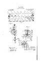
Figure 1 is sectional elevation of my portable scaffold installed in the front Wall of a building under construction.- Fig; 2 is a front elevation of one end of the same. 3 is atop plan view of one end of the scaffold platform.' Fig, 4: is an enlarged frontelevation of the hoistim drum and the related parts of saidsscafi'ol Fig. 5 is a.
brackets detached from the platform.
Referring to the drawings, 1 represents the metal skeleton of a modern building,,
and 2 is the masonry wall for one side thereof that is only partially completed. Secured preferably flat to the roof or on top of this'skeleton, in such manner that one end thereof projects beyond the roof and overhangs the front of the building, are the beams 3 of a suitable outrigger device.
two or more of these There are preferably outrigger beams arranged a suitable distance apart, and they have concave sheaves or pulleys 7 mounted on their ends over which suitable suspending ropes or cables 8 travel. The lower ends ofthe outer stretches of these cables 8, are preferably secured to the outer edge of the platform of my im proved scaffold, and the lower end of the inner stretch of said cable is secured to and wound upon the drum ofa suitable winch,
as will'hereinafter be more fully de 'cribed.
The platform or floor of the sea prises a sufli'cient number of ,j la nks or boards, whose ends rest upon and are secured to metal'sills or cross-members 10, the inner ends of which latter are see red to the centers of length of metal uprig ts 9, and the outer ends .of which are secured to and 1d comsupported by angular struts or braces 12,
the lower ends of which preferablp, to the lower ends ofv said uprights. e outer ends of'the sills 10 have suitable posts 14 secured thereto and, arising therefrom a suitable distance, and a fence or guard-rail 15 consisting of suitable wire netting or other fencing or railing structure, extends between and has its ends secured to said posts. The sills 10 adjacent these posts latter are secured,
are provided with means to which thelower ends of the outer stretches of the hoisting or suspension-cables 8. are secured, and from thence said cables extend to and around sheaves 7 and then down to the hoisting. winches mounted on the platform of the scaffold adjacent uprights9.
The winches just mentioned comprise a suitable winding drum l7 and the shafts upon which said. drums are mounted are preferably arranged at right angles to the front of the building, and have their outer ends journale'd suitable bearings secured to standards 9*, that are secured to and arise from sills 10, and hhve theirnpper ends tied to the uprights 9 both by horizontal tie-bars 9 and by inclined struts 9. The outer ends of drums 17 have a gear 15 secured thereto,- which is, preferably, greater in diameter than the flanged ends of the drum and is engaged by a pinion mounted on the adjzfcent end of a spindle 19 j ournaled in suitable bearings located above thebearings of the drum-shaft, and turned by means of a crank on the outer extended end thereof.
Any kind of a pinion might be used on the spindle l9't6 transmit the motion thereof to the gear 18,-but-I prefer to construct this pinion so that it will hold said gear and drum in any position to which they may be turned. I have, therefore, constructed this pinion of two transverse plates 21, 2i, the former of which is secured directly to the spindle, and the latter of which is separated therefrom by pins 23 that are cast in one piece with said plates. The pins 23 are parallel to the axis of the pinion and are located an equal distance therefromoppo; site each other. The distance between these pins enables the pinion to engage the teeth of the gear 18, and the tendency of the drum and gear to reverse will cause the teeth of the gear to press against the pins of the pinion in a line practically intersecting the axis of the opinion and of the pins thereof, and when at rest said pinion pins will directly oppose the reverse movement of the gear. At the same time, this opposition will not "prevent the operation of the winch, by manual efforts, when it is desired to revolve the same in either direction. The ends of the drums opposite gears 18 are each provided with a suitable ratchet 25, that is engaged by a pawl 26 pivotally connected to uprights 9 that prevent the reverse movement of the drum when the same is at rest.
In order to prevent movement of the platform to or from the building, or horizontally parallel with the adjacent wall thereof, I have provided guide-cables 27, which, although having a certain amount of flexibility, are retained very taut by having their upper ends secured to hangers 28 secured to the top of the building, preferably, above the plane of the beam 3, in such manner that the ends thereof to which said guide-cables are attached overhang the front of the building. The lower end of said cables 27 are sec'uredto the outwardly projecting'ends of brackets 29 that are secured to the structure of the building, preferably, near the foundation thereof, or, if this, IS inconvenient, at some point below the position of the platform of the scaffold. The uprights 9 of they scafl'old at or near both their upper and lower ends are provided with guides through which cables 27 pass, and these guides comprise parallel plates 30 whose ends farthest y from the wall are secured to the uprights 9, in any suitable manner, and whoseoppositc edges have rearwardl projecting arms 31, between which suitab e wheels 32 are journaled in such manner that said wheels come 1 in: contact with and roll against the wall of the" building. Cables 27 extend down between said'plates 30 at suitable-points near uprights 9, and are directed in their movements by concave sheaves or rollers 33. At
. secured to t are engaged by the serrate eccentric perphcry of jaws 35, the trunnions of which are journaled in suitable bearings in plates 30 and have handles 36 that pass forward through openings in the web'of the an leiron uprights 9 at a suitable point, pre erably, above the drum, within convenient reach of the operator without interferring with the manipulation of the winch.
It will be understood that structural changes may be made in the various parts of my improved scafiold without departing from the-spirit of my invention: For example the out-rigger used for supporting the sheaves, around which the hoistin cable ofthe'platform passes, and'the brac ets or members to which the ends of the guidecables are attached, may be materially changed in view of the fact thatthey are dependent to a great extent upon the facilities convenient at hand in the buildin and at the place where the scaffold is erecte It is also apparent that while the triangular frame-work supporting the planks o the platform of my improved scaffold is pre ferred, yet it may be modified, and alsothe railing or fencing on the outer edge of the platform may be disposed with or modified without departing from the novel principles involved in my improvements.
What I claim as newis:
1. A portable scaffold constructed for use on modern high buildings and com rising a platform, transverse-sills upon w ich the ends of said platform rest, u rights medially e rear ends of said sills, and extending both above and below the horizontal plane of the same and formingn per and lower vertical portions which are a out equal in length to the width of the platform,
vertically disposed taut flexible guidecablcs arranged fairly close and substantially parallel to the plane of the wallof the bulldin overhead outrigger-s attached to the' buil ing at or near the top thereof, pulleys journaled in the overhanging portions of said Outriggers, hoisting -cables medially encircling said pulleys and having their inner end portions dependin therefrom and in proximity to and para lel with the guidecables and the outer end portion extending diagonally downward and outward from said pulleys and secured at their lower ektremities tothe outer portions of the sills. and suitable winches supported by the inner portions of said sillsto which the lower extremity of the inner. end portions of said hoisting cables are "movably secured, anflj supporting blocks extending laterally from secured to the rear ends of'said sill s,., -and extending. both above and below theliogie l0.'
' winches siipport'ed by the inner portions of 'theextremities ofthe upper-and lower end.-
portions of the uprights and having openings through which the guide cables pass.
' 2. A portable-scaffold constructed for use on modern high buildings and comprising a v platform, transverse-sills upon which the ends of said platform rest, 'upri ghtsmedi-ally zontal plane of the same and forming upper and lowervertical portions which are about 1 equal in length to the width of the platform,
vertically disposed taut flexible guide'cables arranged fairly close and substantially parallel totheplane of the wall of the building, overhead Outriggers attached to the building at or near the top thereof, pulleys journaled in the overhanging portions of said outriggers, hoisting-cables medially'encircling said said sills to which the' lower extremity of the inner end portions of said hoisting- ,cables are. moyably secured, andsupporting blocks extending laterally from the extremi ties of the upper and lower end portions of .the uprights and having openings through which the guide-cables pass, and rollers jour-' naled in saidblocks and adapted to contact and rollagainst the outer vertical surface of" the building. a v v 3. A portable scafl'old constructed for use on modern high buildings and comprising a platform, transverse sills upon which the V endsofs aid platform rest, uprights medially secured to the rear ends of said sills, and
extending both above and below the horizonand lower vertical portions which are approximately equal inlength to the width the platform, vertically disposed taut fiexible gui egwabQs Qar mged fairly close 'and substantiallyparallel *to] the plane of the wall of'the building, overhead outri'ggers at- ,tal plane of the same and forming upper tached to the building at or near the top thereof, pulleys journaled in the overhang ing portions of said Outriggers hoisting-ca 'bles medially encircling sa-id pulleys and having their inner end portionsdepending therefrom and in proximity to and parallel with the 'guide-cables and the outer end por I tions extending diagonally downward and outward from said pulleysand. secured at 4 their lower extremities to the outer portions of'the sills, and-suitable winches supported by the inn'er portions of said sills to which the lower extremity of the 'inner end portions of said hoisting-cables aremovablys'e cured, and supporting blocks extending lat-- erally from the extremities of the upper'ancl lower end portions of the uprights and hav-' ing openings through which the bles pass, and rollers journaled in said blocks and adapted to contact and-roll against the outer vertical surface of the building; the..-
blocks being separated approximately, the
vertical length of the uprights andthe lower i extremities of the hoistingcables bein separated approximately. the horizontal wldth, of the platform. v
In witness whereof-I have hereuntoset my handthis 23rd day of November, 1912.
' JOHN A. GRANGER. I
Witnesses:
FRANK D. Tnoirasom E. K. LUNDY.
Priority Applications (1)
| Application Number | Priority Date | Filing Date | Title |
|---|---|---|---|
| US73398912A US1136898A (en) | 1912-11-29 | 1912-11-29 | Portable scaffold. |
Applications Claiming Priority (1)
| Application Number | Priority Date | Filing Date | Title |
|---|---|---|---|
| US73398912A US1136898A (en) | 1912-11-29 | 1912-11-29 | Portable scaffold. |
Publications (1)
| Publication Number | Publication Date |
|---|---|
| US1136898A true US1136898A (en) | 1915-04-20 |
Family
ID=3205002
Family Applications (1)
| Application Number | Title | Priority Date | Filing Date |
|---|---|---|---|
| US73398912A Expired - Lifetime US1136898A (en) | 1912-11-29 | 1912-11-29 | Portable scaffold. |
Country Status (1)
| Country | Link |
|---|---|
| US (1) | US1136898A (en) |
Cited By (2)
| Publication number | Priority date | Publication date | Assignee | Title |
|---|---|---|---|---|
| US3111764A (en) * | 1955-11-25 | 1963-11-26 | Clell C Mayes | Brick laying device |
| DE102004009865A1 (en) * | 2004-02-25 | 2005-09-15 | Klaus Sonnen | Process and gondola assembly to install hanging external scaffold frame around high building structure |
-
1912
- 1912-11-29 US US73398912A patent/US1136898A/en not_active Expired - Lifetime
Cited By (3)
| Publication number | Priority date | Publication date | Assignee | Title |
|---|---|---|---|---|
| US3111764A (en) * | 1955-11-25 | 1963-11-26 | Clell C Mayes | Brick laying device |
| DE102004009865A1 (en) * | 2004-02-25 | 2005-09-15 | Klaus Sonnen | Process and gondola assembly to install hanging external scaffold frame around high building structure |
| DE102004009865B4 (en) * | 2004-02-25 | 2009-07-30 | Klaus Sonnen | Device for bridge remediation works |
Similar Documents
| Publication | Publication Date | Title |
|---|---|---|
| US2203113A (en) | Hoist | |
| US4074789A (en) | Mobile rolling support system for scaffolding used in building construction | |
| US483001A (en) | Combined water-tower and fire-escape | |
| US1136898A (en) | Portable scaffold. | |
| US3127996A (en) | Climbing cranes | |
| US2890082A (en) | Hoisting attachment for tubular steel scaffolds | |
| US2284360A (en) | Extendible builder's tower | |
| CN103623510B (en) | Cable guide tracked elevator tall-building fire fighting bridge | |
| CN207513201U (en) | A kind of roofing cornices installation mobile device | |
| US1111814A (en) | Builder's scaffold. | |
| US763274A (en) | Scaffold. | |
| CN210419022U (en) | Tower crane standard knot with safety performance | |
| AT140282B (en) | Tower car with telescopic mast and work platform. | |
| US1168436A (en) | Scaffold. | |
| CN114482510B (en) | An all-steel synchronous lifting platform aisle plate device | |
| US1539344A (en) | Mast hoist | |
| CN104612060A (en) | Construction work rack below roof on outer side of prefabricated boundary beam | |
| US1147541A (en) | Scaffold. | |
| US1852524A (en) | Suspended scaffold | |
| US1188283A (en) | Portable fire-escape tower. | |
| US2072355A (en) | Scaffolding | |
| US1004876A (en) | Hanging scaffold. | |
| CN211472189U (en) | Construction platform and construction system | |
| DE802720C (en) | House trusses | |
| CH125056A (en) | Tower crane. |