US11368805B2 - Test circuit, test method and audio codec for stereo microphones - Google Patents
Test circuit, test method and audio codec for stereo microphones Download PDFInfo
- Publication number
- US11368805B2 US11368805B2 US17/090,929 US202017090929A US11368805B2 US 11368805 B2 US11368805 B2 US 11368805B2 US 202017090929 A US202017090929 A US 202017090929A US 11368805 B2 US11368805 B2 US 11368805B2
- Authority
- US
- United States
- Prior art keywords
- data
- microphone
- count value
- circuit
- comparison result
- Prior art date
- Legal status (The legal status is an assumption and is not a legal conclusion. Google has not performed a legal analysis and makes no representation as to the accuracy of the status listed.)
- Active
Links
Images


Classifications
-
- H—ELECTRICITY
- H04—ELECTRIC COMMUNICATION TECHNIQUE
- H04R—LOUDSPEAKERS, MICROPHONES, GRAMOPHONE PICK-UPS OR LIKE ACOUSTIC ELECTROMECHANICAL TRANSDUCERS; ELECTRIC HEARING AIDS; PUBLIC ADDRESS SYSTEMS
- H04R29/00—Monitoring arrangements; Testing arrangements
- H04R29/004—Monitoring arrangements; Testing arrangements for microphones
- H04R29/005—Microphone arrays
- H04R29/006—Microphone matching
-
- G—PHYSICS
- G10—MUSICAL INSTRUMENTS; ACOUSTICS
- G10L—SPEECH ANALYSIS TECHNIQUES OR SPEECH SYNTHESIS; SPEECH RECOGNITION; SPEECH OR VOICE PROCESSING TECHNIQUES; SPEECH OR AUDIO CODING OR DECODING
- G10L19/00—Speech or audio signals analysis-synthesis techniques for redundancy reduction, e.g. in vocoders; Coding or decoding of speech or audio signals, using source filter models or psychoacoustic analysis
-
- G—PHYSICS
- G10—MUSICAL INSTRUMENTS; ACOUSTICS
- G10L—SPEECH ANALYSIS TECHNIQUES OR SPEECH SYNTHESIS; SPEECH RECOGNITION; SPEECH OR VOICE PROCESSING TECHNIQUES; SPEECH OR AUDIO CODING OR DECODING
- G10L25/00—Speech or voice analysis techniques not restricted to a single one of groups G10L15/00 - G10L21/00
- G10L25/48—Speech or voice analysis techniques not restricted to a single one of groups G10L15/00 - G10L21/00 specially adapted for particular use
- G10L25/51—Speech or voice analysis techniques not restricted to a single one of groups G10L15/00 - G10L21/00 specially adapted for particular use for comparison or discrimination
-
- H—ELECTRICITY
- H04—ELECTRIC COMMUNICATION TECHNIQUE
- H04R—LOUDSPEAKERS, MICROPHONES, GRAMOPHONE PICK-UPS OR LIKE ACOUSTIC ELECTROMECHANICAL TRANSDUCERS; ELECTRIC HEARING AIDS; PUBLIC ADDRESS SYSTEMS
- H04R1/00—Details of transducers, loudspeakers or microphones
- H04R1/20—Arrangements for obtaining desired frequency or directional characteristics
- H04R1/32—Arrangements for obtaining desired frequency or directional characteristics for obtaining desired directional characteristic only
- H04R1/40—Arrangements for obtaining desired frequency or directional characteristics for obtaining desired directional characteristic only by combining a number of identical transducers
- H04R1/406—Arrangements for obtaining desired frequency or directional characteristics for obtaining desired directional characteristic only by combining a number of identical transducers microphones
-
- H—ELECTRICITY
- H04—ELECTRIC COMMUNICATION TECHNIQUE
- H04R—LOUDSPEAKERS, MICROPHONES, GRAMOPHONE PICK-UPS OR LIKE ACOUSTIC ELECTROMECHANICAL TRANSDUCERS; ELECTRIC HEARING AIDS; PUBLIC ADDRESS SYSTEMS
- H04R3/00—Circuits for transducers
- H04R3/005—Circuits for transducers for combining the signals of two or more microphones
-
- H—ELECTRICITY
- H04—ELECTRIC COMMUNICATION TECHNIQUE
- H04R—LOUDSPEAKERS, MICROPHONES, GRAMOPHONE PICK-UPS OR LIKE ACOUSTIC ELECTROMECHANICAL TRANSDUCERS; ELECTRIC HEARING AIDS; PUBLIC ADDRESS SYSTEMS
- H04R5/00—Stereophonic arrangements
- H04R5/027—Spatial or constructional arrangements of microphones, e.g. in dummy heads
Definitions
- the present invention generally relates to a stereo (two-channel) microphone, and, more particularly, to a test circuit, test method and audio codec for the stereo microphone.
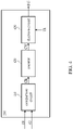
- FIG. 1 is a functional block diagram of a conventional stereo microphone system.
- the stereo microphone system 100 includes a stereo microphone 110 and an audio codec 120 .
- the stereo microphone 110 which is soldered on a printed circuit board (PCB), includes a microphone 112 and a microphone 114 .
- the microphones 112 and 114 may be microphones fabricated using the microelectromechanical system (MEMS) technology.
- the microphone 112 has a clock pin cp 1 , a data output pin dp 1 and a selection pin SLC 1 .
- the microphone 114 has a clock pin cp 2 , a data output pin dp 2 and a selection pin SLC 2 .
- the clock pin cp 1 and the clock pin cp 2 are electrically connected on the PCB and simultaneously receive the clock CLK provided by the audio codec 120 .
- the microphone 112 and the microphone 114 operate according to the clock CLK.
- the data output pin dp 1 and the data output pin dp 2 are electrically connected on the PCB.
- the microphone 112 outputs the one-bit pulse density modulation (PDM) data d 1 through the data output pin dp 1
- the microphone 114 outputs the one-bit PDM data d 2 through the data output pin dp 2 .
- Data D is a combination of the data d 1 and the data d 2 .
- the audio codec 120 provides the clock CLK for the stereo microphone 110 through a clock pin and receives the data D (which includes the data d 1 and the data d 2 ) generated by the stereo microphone 110 through a data pin. After receiving multiple sets of data d 1 and multiple sets of data d 2 , the audio codec 120 decodes or filters the data d 1 and the data d 2 to generate a multi-bit pulse-code modulation (PCM) data D_PCM.
- PCM pulse-code modulation
- FIG. 2 shows the data d 1 , the data d 2 , the data D and the clock CLK.
- a the selection pin SLC 1 is connected to the voltage source VDD and the selection pin SLC 2 is grounded, when the clock CLK is at a high level (i.e., logic 1), the output data d 1 of the microphone 112 has a value (i.e., the bit value “value1” in FIG. 2 which can be binary “1” or binary “0”), whereas the output data d 2 of the microphone 114 is high impedance (i.e., “Z” in FIG.
- the output data d 1 of the microphone 112 is high impedance (“Z”), whereas the output data d 2 of the microphone 114 has a value (i.e., the bit value “value2” in FIG. 2 which can be binary “1” or binary “0”).
- the content of the data D is the alternate arrangement of the bit values value1 and the bit values value2, which is equivalent to the alternate arrangement of the data d 1 and the data d 2 .
- the microphone 112 and the microphone 114 are not firmly soldered on the PCB. More specifically, the clock pin cp 1 , the data output pin dp 1 , the clock pin cp 2 and the data output pin dp 2 may be floating, resulting in an error in the stereo microphone 110 due to the failure in the physical connection required for information or communication path between the audio codec 120 and the microphone 112 and/or the microphone 114 .
- spotting the pin that is floating due to soldering with human eyes can be a difficult task, and thus debugging the circuit becomes an issue.
- an object of the present invention is to provide a test circuit, test methods and an audio codec for a stereo microphone, so as to make an improvement to the prior art.
- a circuit for testing a microphone module (e.g., a stereo microphone) is provided.
- the microphone module operates according to a clock and includes a first microphone and a second microphone.
- the first microphone outputs a first data through a first data output pin when the clock is at a first level
- the second microphone outputs a second data through a second data output pin when the clock is at a second level.
- the first level is different from the second level.
- the first data output pin and the second data output pin are coupled to a capacitor.
- the circuit includes a comparison circuit, a counter and a decision circuit.
- the comparison circuit is configured to compare the first data and the second data and to generate a comparison result.
- the counter is coupled to the comparison circuit and configured to generate a count value based on the comparison result.
- the decision circuit is coupled to the counter and configured to determine whether there is an error in the microphone module based on the count value and a threshold value.
- a method of testing a microphone module (e.g., a stereo microphone) is provided.
- the microphone module operates according to a clock and includes a first microphone and a second microphone.
- the first microphone outputs a first data through a first data output pin when the clock is at a first level
- the second microphone outputs a second data through a second data output pin when the clock is at a second level.
- the first level is different from the second level.
- the first data output pin and the second data output pin are coupled to a capacitor.
- the method includes the following steps: (a) comparing the first data with the second data and generating a comparison result; (b) generating a count value based on the comparison result; and (c) determining whether there is an error in the microphone module based on the count value and a threshold value.
- a method of testing a microphone module (e.g., a stereo microphone) is provided.
- the microphone module operates according to a clock and includes a first microphone and a second microphone.
- the first microphone outputs a plurality of first data through a first data output pin when the clock is at a first level
- the second microphone outputs a plurality of second data through a second data output pin when the clock is at a second level.
- the first level is different from the second level.
- the first data output pin and the second data output pin are coupled to a capacitor.
- the method includes the following steps: (a) decoding or filtering the first data and the second data to generate a first pulse-code modulation (PCM) data and a second PCM data; (b) comparing the first PCM data with the second PCM data and generating a comparison result; (c) generating a count value based on the comparison result; and (d) determining whether there is an error in the microphone module based on the count value and a threshold value.
- PCM pulse-code modulation
- An audio codec for testing a microphone module (e.g., a stereo microphone) is provided.
- the microphone module operates according to a clock and includes a first microphone and a second microphone.
- the first microphone outputs a plurality of first data through a first data output pin when the clock is at a first level
- the second microphone outputs a plurality of second data through a second data output pin when the clock is at a second level.
- the first level is different from the second level.
- the first data output pin and the second data output pin are coupled to a capacitor.
- the audio codec includes a memory and a processor.
- the memory is configured to store a plurality of program instructions or program codes.
- the processor is coupled to the memory and configured to execute the program instructions or program codes to perform the following steps: (a) decoding or filtering the first data and the second data to generate a first pulse-code modulation (PCM) data and a second PCM data; (b) comparing the first PCM data with the second PCM data and generating a comparison result; (c) generating a count value based on the comparison result; and (d) determining whether there is an error in the microphone module based on the count value and a threshold value.
- PCM pulse-code modulation
- the test circuit, test methods and audio codec for the stereo microphone can quickly find out whether there is an error in the stereo microphone.
- the present invention makes circuit debugging faster and thus saves time.
- FIG. 1 illustrates a functional block diagram of a conventional stereo microphone system.
- FIG. 2 illustrates a timing diagram of the data d 1 , data d 2 , data D and clock CLK.
- FIG. 3 illustrates a functional block diagram of the stereo microphone system according to the present invention.
- FIG. 4 illustrates a functional block diagram of a test circuit according to an embodiment of the present invention.
- FIG. 5 illustrates a flowchart of the test method according to an embodiment of the present invention.
- FIG. 6 illustrates an embodiment of the comparison circuit of FIG. 4 .
- FIG. 7 illustrates a functional block diagram of the stereo microphone system according to another embodiment of the present invention.
- FIG. 8 illustrates a flowchart of the test method according to another embodiment of the present invention.
- connection between objects or events in the below-described embodiments can be direct or indirect provided that these embodiments are practicable under such connection.
- Said “indirect” means that an intermediate object or a physical space exists between the objects, or an intermediate event or a time interval exists between the events.
- test circuits for stereo microphones.
- the audio codec for stereo microphones.
- the detail of such elements is omitted provided that such detail has little to do with the features of this disclosure, and that this omission nowhere dissatisfies the specification and enablement requirements.
- Some or all of the processes of the test methods may be implemented by software and/or firmware and can be performed by the test circuits, the audio codec or their equivalents.
- a person having ordinary skill in the art can choose components or steps equivalent to those described in this specification to carry out the present invention, which means that the scope of this invention is not limited to the embodiments in the specification.
- Coupled and the term “connected” may mean “directly coupled” and “directly connected” respectively, or “indirectly coupled” and “indirectly connected” respectively. “Coupled” and “connected” may also be used to indicate that two or more elements cooperate or interact with each other.
- first may be termed a second element, and, similarly, a second element could be termed a first element, without departing from the scope of the embodiments.
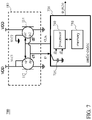
- FIG. 3 is a functional block diagram of the stereo microphone system according to the present invention.
- the stereo microphone system 200 includes a stereo microphone 110 and an audio codec 220 .
- the audio codec 220 may be a system on chip (SoC).
- SoC system on chip
- the stereo microphone 110 and the audio codec 220 are soldered on a PCB (not shown).
- the audio codec 220 samples the data D with the capacitor 225 provided therein. One end of the capacitor 225 is grounded, and the other end of the capacitor 225 is coupled to one of the pins of the audio codec 220 ; through that pin, the audio codec 220 receives the data D.
- the audio codec 220 can retrieve the data d 1 and the data d 2 from the data D according to the clock CLK and the terminal voltage of the capacitor 225 .
- the audio codec 220 decodes or filters the data d 1 and the data d 2 to generate multiple multi-bit PCM data D_PCM.
- the data D has specific contents.
- the clock pin cp 1 or the data output pin dp 1 is floating, the data d 1 is in the high impedance state; therefore, the terminal voltage of the capacitor 225 does not change (i.e., the previous state of the terminal voltage is maintained) at the high levels of the clock CLK.
- the content of the data D includes only the data d 2 , and therefore, a same sampled result (i.e., the data d 2 ) is obtained by the audio codec 220 during both the high levels and the low levels of the clock CLK.
- the stereo microphone 110 is not firmly soldered on the PCB, two identical data are sampled by the audio codec 220 within one cycle of the clock CLK.
- the audio codec 220 uses a built-in test circuit 230 to test the stereo microphone 110 .
- FIG. 4 is a functional block diagram of the test circuit according to an embodiment of the present invention.
- FIG. 5 is a flowchart of the test method according to an embodiment of the present invention. Reference is made to both FIG. 4 and FIG. 5 for the discussions below.
- the test circuit 230 includes a comparison circuit 410 , a counter 420 and a decision circuit 430 .
- the comparison circuit 410 compares the data d 1 and the data d 2 and accordingly generates a comparison result CR (step S 510 ).
- the counter 420 generates a count value CV based on the comparison result CR (step S 520 ).
- the decision circuit 430 Based on the count value CV and the threshold value Th, the decision circuit 430 generates a flag FG to indicate whether an error has occurred to the stereo microphone 110 (step S 530 ).
- the details of each element and step are discussed below.
- the comparison circuit 410 and step S 510 can be implemented with a logic gate.
- the logic gate 500 includes two input terminals and one output terminal. The two input terminals of the logic gate 500 respectively receive the data d 1 and the data d 2 , and the output terminal outputs the comparison result CR.
- the logic gate 500 outputs a logic 1 when the data d 1 is the same as the data d 2
- the logic gate 500 outputs a logic 0 when the data d 1 is different from the data d 2 .
- the logic gate 500 may be an exclusive NOR gate (XNOR gate).
- the logic gate 500 outputs a logic 1 when the data d 1 is different from the data d 2 , and the logic gate 500 outputs a logic 0 when the data d 1 is the same as the data d 2 .
- the logic gate 500 may be an exclusion OR gate (XOR gate).
- Step S 520 includes sub-steps S 522 , S 524 and S 526 .
- the counter 420 increases the count value CV (step S 524 ) when the comparison result CR is logic 1 (YES branch of step S 522 ), and the counter 420 resets the count value CV (i.e., zeroing the count value CV) (step S 526 ) when the comparison result CR is logic 0 (NO branch of step S 522 ).
- the counter 420 resets the count value CV (step S 526 ) when the comparison result CR is logic 1 (NO branch of step S 522 ), and the counter 420 increases the count value CV (step S 524 ) when the comparison result CR is logic 0 (YES branch of step S 522 ).
- Step S 530 includes sub-steps S 532 , S 534 and S 536 .
- the decision circuit 430 compares the count value CV with the threshold value Th.
- the decision circuit 430 sets the flag FG to the first logical value (e.g., logic 1) to indicate that there is an error in the stereo microphone (step S 534 ).
- the decision circuit 430 sets the flag FG to a second logical value (e.g., logic 0) to indicate that there is no error in the stereo microphone (step S 536 ).
- the first logical value is different from the second logical value.
- the decision circuit 430 may be implemented with a comparator.
- the threshold value Th can be set based on experiences, for example, hundreds or thousands.
- test circuit 230 and the corresponding test method can find out whether the stereo microphone 110 is abnormal, which helps the circuit designers be aware of the errors in an early stage.
- the abnormality of the stereo microphone 110 may include, but not limited to, the data output pins and/or clock pins of the microphone 112 and/or the microphone 114 being floating.
- FIG. 7 is a functional block diagram of the stereo microphone system according to another embodiment of the present invention.
- the stereo microphone system 700 includes the stereo microphone 110 and an audio codec 720 .
- the audio codec 720 includes a capacitor 725 , a processor 740 and a memory 750 .
- the audio codec 720 can be an SoC.
- the stereo microphone 110 and the audio codec 720 are soldered on a PCB (not shown).
- the audio codec 720 samples the data D through the capacitor 725 .
- One end of the capacitor 725 is grounded, and the other end of the capacitor 725 is coupled to one of the pins of the audio codec 720 ; through that pin, the audio codec 720 receives the data D.
- the audio codec 720 can retrieve the data d 1 and the data d 2 from the data D according to the clock CLK and the terminal voltage of the capacitor 725 .
- the audio codec 720 decodes or filters the data d 1 and the data d 2 to generate multiple multi-bit PCM data D_PCM.
- the processor 740 may be a circuit or an electronic component with program execution capability, such as a central processing unit (CPU), a microprocessor, a micro-processing unit or an application-specific integrated circuit (ASIC).
- the processor 740 executes multiple program codes or program instructions stored in the memory 750 to process the data d 1 and the data d 2 .
- the ASIC can be a digital signal processor (DSP).
- DSP digital signal processor
- the stereo microphone 110 is tested by the processor 740 executing software and/or firmware (i.e., executing the program codes or program instructions stored in the memory 750 ).
- FIG. 8 is a flowchart of the test method according to another embodiment of the present invention. The method of FIG. 8 is executed by the audio codec 720 and the processor 740 .
- the processor 740 decodes or filters multiple data d 1 and multiple data d 2 to generate the PCM data D_PCM 1 and the PCM data D_PCM 2 (step S 810 ).
- the audio codec 720 outputs the PCM data D_PCM 1 and the PCM data D_PCM 2 simultaneously or alternately.
- the PCM data D_PCM contains the PCM data D_PCM 1 and the PCM data D_PCM 2 .
- the PCM data D_PCM 1 corresponds to one channel of the stereo microphone 110
- the PCM data D_PCM 2 corresponds to the other channel of the stereo microphone 110 .
- Step S 810 is well-known to people having ordinary skill in the art, and the details are thus omitted for brevity.
- the processor 740 compares the PCM data D_PCM 1 with the PCM data D_PCM 2 and accordingly generates a comparison result CR (step S 820 ), generates a count value CV based on the comparison result CR (step S 830 ), and then determines whether an error has occurred to the stereo microphone 110 based on the count value CV and the threshold value Th (step S 840 ).
- Steps S 820 , S 830 and S 840 are similar to steps S 510 , S 520 and S 530 , respectively, and the details are thus omitted for brevity.
Landscapes
- Engineering & Computer Science (AREA)
- Health & Medical Sciences (AREA)
- Physics & Mathematics (AREA)
- Acoustics & Sound (AREA)
- Signal Processing (AREA)
- Otolaryngology (AREA)
- General Health & Medical Sciences (AREA)
- Computational Linguistics (AREA)
- Audiology, Speech & Language Pathology (AREA)
- Human Computer Interaction (AREA)
- Multimedia (AREA)
- Circuit For Audible Band Transducer (AREA)
- Electrostatic, Electromagnetic, Magneto- Strictive, And Variable-Resistance Transducers (AREA)
Abstract
Description
Claims (11)
Applications Claiming Priority (2)
| Application Number | Priority Date | Filing Date | Title |
|---|---|---|---|
| TW108140873A TWI722648B (en) | 2019-11-11 | 2019-11-11 | Test circuit, test method and audio codec for stereo microphones |
| TW108140873 | 2019-11-11 |
Publications (2)
| Publication Number | Publication Date |
|---|---|
| US20210144501A1 US20210144501A1 (en) | 2021-05-13 |
| US11368805B2 true US11368805B2 (en) | 2022-06-21 |
Family
ID=75847079
Family Applications (1)
| Application Number | Title | Priority Date | Filing Date |
|---|---|---|---|
| US17/090,929 Active US11368805B2 (en) | 2019-11-11 | 2020-11-06 | Test circuit, test method and audio codec for stereo microphones |
Country Status (2)
| Country | Link |
|---|---|
| US (1) | US11368805B2 (en) |
| TW (1) | TWI722648B (en) |
Citations (3)
| Publication number | Priority date | Publication date | Assignee | Title |
|---|---|---|---|---|
| TW594025B (en) | 2002-12-31 | 2004-06-21 | Via Tech Inc | Method and device for determining signal transmission quality of circuit board |
| CN109068238A (en) | 2018-10-09 | 2018-12-21 | 晶晨半导体(上海)股份有限公司 | microphone and intelligent sound box |
| US20190079573A1 (en) * | 2017-09-12 | 2019-03-14 | Ambiq Micro, Inc. | Very Low Power Microcontroller System |
-
2019
- 2019-11-11 TW TW108140873A patent/TWI722648B/en active
-
2020
- 2020-11-06 US US17/090,929 patent/US11368805B2/en active Active
Patent Citations (3)
| Publication number | Priority date | Publication date | Assignee | Title |
|---|---|---|---|---|
| TW594025B (en) | 2002-12-31 | 2004-06-21 | Via Tech Inc | Method and device for determining signal transmission quality of circuit board |
| US20190079573A1 (en) * | 2017-09-12 | 2019-03-14 | Ambiq Micro, Inc. | Very Low Power Microcontroller System |
| CN109068238A (en) | 2018-10-09 | 2018-12-21 | 晶晨半导体(上海)股份有限公司 | microphone and intelligent sound box |
Non-Patent Citations (2)
| Title |
|---|
| OA letter of the counterpart CN application (appl. No. 201911129915.1) dated Dec. 1, 2021. Summary of the OA letter: Claims 1-9 are unpatentable over CN109068238 and TW594025B. |
| OA letter of the counterpart TW application (appl. No. 108140873) dated Oct. 15, 2020. Summary of the OA letter: Claims 1-9 are rejected under Taiwan Patent Law Article 22(2) as being unpatentable over reference 1 (US 2019/0079573 A1). |
Also Published As
| Publication number | Publication date |
|---|---|
| TW202119400A (en) | 2021-05-16 |
| US20210144501A1 (en) | 2021-05-13 |
| TWI722648B (en) | 2021-03-21 |
Similar Documents
| Publication | Publication Date | Title |
|---|---|---|
| US11368805B2 (en) | Test circuit, test method and audio codec for stereo microphones | |
| CN110853696B (en) | Wafer acceptance test module and method for static memory function detection | |
| US8362799B2 (en) | Semiconductor device, and failure detection system and failure detection method of data hold circuit | |
| US20060190792A1 (en) | Electronic element comprising an electronic circuit which is to be tested and test system arrangement which is used to test the electronic element | |
| US11686769B1 (en) | Signal toggling detection and correction circuit | |
| TWI607222B (en) | Semiconductor device | |
| CN112822621B (en) | Test circuit and test method of dual-channel microphone and audio codec | |
| EP4575531A1 (en) | System and method for validating critical paths of integrated circuits | |
| JP4242741B2 (en) | Signal processing circuit for debugging | |
| JP2009122009A (en) | Test circuit | |
| TW201610663A (en) | Error detection in stored data values | |
| CN113311319A (en) | Integrated circuit chip and configuration method, and test system and test method | |
| US10746791B2 (en) | Glitch measurement device and glitch measurement method | |
| CN101047380B (en) | Common input/output terminal control circuit | |
| US20100109720A1 (en) | Semiconductor integrated circuit and control method of the same | |
| CN112532214B (en) | Detection method and circuit for judging whether clock signal is accurate | |
| US11243587B2 (en) | Data processing device | |
| US7184545B2 (en) | Semiconductor integrated circuit and method of testing semiconductor integrated circuit | |
| US8169228B2 (en) | Chip testing circuit | |
| US20250102571A1 (en) | Failure detection circuit, semiconductor device and failure detection method | |
| JP2001345699A (en) | Testing circuit of analog-to-digital converter and its testing method | |
| CN120260631B (en) | Delayed power-down control circuit, memory chip and its reset method | |
| US11307767B1 (en) | System for controlling memory operations in system-on-chips | |
| US20240428878A1 (en) | Memory device and control method therefor | |
| JP2735010B2 (en) | Semiconductor device and test method thereof |
Legal Events
| Date | Code | Title | Description |
|---|---|---|---|
| AS | Assignment |
Owner name: REALTEK SEMICONDUCTOR CORPORATION, TAIWAN Free format text: ASSIGNMENT OF ASSIGNORS INTEREST;ASSIGNORS:YEH, TSUNG-LI;HUANG, YI-CHENG;REEL/FRAME:054292/0532 Effective date: 20200709 |
|
| FEPP | Fee payment procedure |
Free format text: ENTITY STATUS SET TO UNDISCOUNTED (ORIGINAL EVENT CODE: BIG.); ENTITY STATUS OF PATENT OWNER: LARGE ENTITY |
|
| STPP | Information on status: patent application and granting procedure in general |
Free format text: DOCKETED NEW CASE - READY FOR EXAMINATION |
|
| STPP | Information on status: patent application and granting procedure in general |
Free format text: NON FINAL ACTION MAILED |
|
| STPP | Information on status: patent application and granting procedure in general |
Free format text: RESPONSE TO NON-FINAL OFFICE ACTION ENTERED AND FORWARDED TO EXAMINER |
|
| STPP | Information on status: patent application and granting procedure in general |
Free format text: NOTICE OF ALLOWANCE MAILED -- APPLICATION RECEIVED IN OFFICE OF PUBLICATIONS |
|
| STPP | Information on status: patent application and granting procedure in general |
Free format text: PUBLICATIONS -- ISSUE FEE PAYMENT VERIFIED |
|
| STCF | Information on status: patent grant |
Free format text: PATENTED CASE |
|
| MAFP | Maintenance fee payment |
Free format text: PAYMENT OF MAINTENANCE FEE, 4TH YEAR, LARGE ENTITY (ORIGINAL EVENT CODE: M1551); ENTITY STATUS OF PATENT OWNER: LARGE ENTITY Year of fee payment: 4 |