US11368784B2 - Receiver unit having pressure equilibrium structure and compensation structure for low frequency - Google Patents
Receiver unit having pressure equilibrium structure and compensation structure for low frequency Download PDFInfo
- Publication number
- US11368784B2 US11368784B2 US17/094,090 US202017094090A US11368784B2 US 11368784 B2 US11368784 B2 US 11368784B2 US 202017094090 A US202017094090 A US 202017094090A US 11368784 B2 US11368784 B2 US 11368784B2
- Authority
- US
- United States
- Prior art keywords
- receiver
- casing
- low frequency
- receiver unit
- lower casing
- Prior art date
- Legal status (The legal status is an assumption and is not a legal conclusion. Google has not performed a legal analysis and makes no representation as to the accuracy of the status listed.)
- Active
Links
Images


Classifications
-
- H—ELECTRICITY
- H04—ELECTRIC COMMUNICATION TECHNIQUE
- H04R—LOUDSPEAKERS, MICROPHONES, GRAMOPHONE PICK-UPS OR LIKE ACOUSTIC ELECTROMECHANICAL TRANSDUCERS; ELECTRIC HEARING AIDS; PUBLIC ADDRESS SYSTEMS
- H04R1/00—Details of transducers, loudspeakers or microphones
- H04R1/10—Earpieces; Attachments therefor ; Earphones; Monophonic headphones
- H04R1/1083—Reduction of ambient noise
-
- H—ELECTRICITY
- H04—ELECTRIC COMMUNICATION TECHNIQUE
- H04R—LOUDSPEAKERS, MICROPHONES, GRAMOPHONE PICK-UPS OR LIKE ACOUSTIC ELECTROMECHANICAL TRANSDUCERS; ELECTRIC HEARING AIDS; PUBLIC ADDRESS SYSTEMS
- H04R1/00—Details of transducers, loudspeakers or microphones
- H04R1/20—Arrangements for obtaining desired frequency or directional characteristics
- H04R1/22—Arrangements for obtaining desired frequency or directional characteristics for obtaining desired frequency characteristic only
- H04R1/28—Transducer mountings or enclosures modified by provision of mechanical or acoustic impedances, e.g. resonator, damping means
- H04R1/2807—Enclosures comprising vibrating or resonating arrangements
- H04R1/2815—Enclosures comprising vibrating or resonating arrangements of the bass reflex type
- H04R1/2823—Vents, i.e. ports, e.g. shape thereof or tuning thereof with damping material
-
- H—ELECTRICITY
- H04—ELECTRIC COMMUNICATION TECHNIQUE
- H04R—LOUDSPEAKERS, MICROPHONES, GRAMOPHONE PICK-UPS OR LIKE ACOUSTIC ELECTROMECHANICAL TRANSDUCERS; ELECTRIC HEARING AIDS; PUBLIC ADDRESS SYSTEMS
- H04R1/00—Details of transducers, loudspeakers or microphones
- H04R1/02—Casings; Cabinets ; Supports therefor; Mountings therein
-
- H—ELECTRICITY
- H04—ELECTRIC COMMUNICATION TECHNIQUE
- H04R—LOUDSPEAKERS, MICROPHONES, GRAMOPHONE PICK-UPS OR LIKE ACOUSTIC ELECTROMECHANICAL TRANSDUCERS; ELECTRIC HEARING AIDS; PUBLIC ADDRESS SYSTEMS
- H04R1/00—Details of transducers, loudspeakers or microphones
- H04R1/10—Earpieces; Attachments therefor ; Earphones; Monophonic headphones
- H04R1/1016—Earpieces of the intra-aural type
-
- H—ELECTRICITY
- H04—ELECTRIC COMMUNICATION TECHNIQUE
- H04R—LOUDSPEAKERS, MICROPHONES, GRAMOPHONE PICK-UPS OR LIKE ACOUSTIC ELECTROMECHANICAL TRANSDUCERS; ELECTRIC HEARING AIDS; PUBLIC ADDRESS SYSTEMS
- H04R2460/00—Details of hearing devices, i.e. of ear- or headphones covered by H04R1/10 or H04R5/033 but not provided for in any of their subgroups, or of hearing aids covered by H04R25/00 but not provided for in any of its subgroups
- H04R2460/11—Aspects relating to vents, e.g. shape, orientation, acoustic properties in ear tips of hearing devices to prevent occlusion
Definitions
- the present disclosure relates to a receiver unit having a pressure equilibrium structure and a compensation structure for a low frequency.
- Earphones are classified into a closed earphone in which the rest of the earphone is blocked except for a sound radiating hole inserted into an ear canal and an open earphone including a tuning hole and a duct in addition to the sound radiating hole.
- the closed earphone which transmits a sound of a receiver installed therein directly into a user's ear, enables the user to hear a sound even with small power, and in particular, a canal-type earphone inserted into the user's ear through an earpiece has the advantage of excellent sound insulation to block ambient noise.
- Korean Patent Registration No. 10-1558091 discloses a canal-type earphone including a pressure equilibrium means to improve the pressure difference.
- FIG. 1 is a view showing a canal-type earphone including a pressure equilibrium means according to the related art.
- a canal-type earphone 1 according to the related art includes a speaker unit 10 , a housing 20 accommodating the speaker unit 10 , and an earpiece 23 installed on an outer surface of a tube 25 integrally formed on a front portion of the housing 20 .
- the speaker unit 10 installed in the housing 20 includes a cylindrical frame 11 , a magnetic circuit 15 , 16 installed in the frame 11 , and a diaphragm 13 that vibrates up and down by a magnetic force of the magnetic circuit 15 , 16 .
- the frame 11 has a cylindrical shape and includes a cover 18 installed at a front and a bracket 19 installed at a rear.
- a through hole 18 a is provided at the center of the cover 18 to emit sound generated in the diaphragm 13 forward.
- a through hole 19 a is provided at the center of the bracket 19 to discharge the sound generated in the diaphragm 13 to the rear.
- a through hole 16 a is provided at the center of a yoke 16 to emit the sound generated in the diaphragm 13 to the rear.
- a gasket 30 is installed on a front surface of the cover 18 .
- the gasket 30 is formed of an elastic material such as rubber or silicone.
- a through hole 30 a is provided at the center of the gasket 30 to discharge sound emitted from the speaker unit 10 .
- a pressure equilibrium means for discharging air present at the front of the speaker unit 10 to the rear of the speaker unit 10 to eliminate a pressure difference between the user's ear canal and ambient air is provided.
- the pressure equilibrium means of the earphone according to the related art includes a side air passage 50 for discharging air inside A the tube 25 or air inside B the speaker unit 10 to a side surface C of the gasket 30 or a side surface D of the speaker unit 10 and a rear air passage 60 for discharging air on the side surface C of the gasket 30 or the side surface D of the speaker unit 10 to the rear E of the speaker unit 10 .
- an object of the present disclosure is to provide a receiver unit for a canal-type earphone, capable of compensating for a decrease in sound pressure in a low frequency range, while improving a difference in pressure between an ear canal and outside, when the canal-type earphone is worn.
- a receiver unit having a pressure equilibrium structure and a compensation structure for a low frequency including: a receiver including a frame, a magnetic circuit, a voice coil, and a diaphragm; an upper casing covering an upper portion and a side surface of the receiver and having a sound insulation hole; and a lower casing attached to a lower surface of the receiver and coupled to the upper casing, wherein a ventilation recess is provided on an outer surface of the upper casing to allow air to flow between an upper space of the upper casing and a lower space of the lower casing, the receiver includes a back hole, and the lower casing includes a duct connecting the back hole and the lower space of the lower casing.
- the receiver unit may further include: at least one acoustic mesh located in a duct path and compensating for a reduction in a low frequency.
- the acoustic mesh may be attached to cover the back hole of the receiver, and the acoustic mesh may be accommodated in a duct of the lower casing.
- the acoustic mesh may be attached to a lower surface of the lower casing to cover an end of the duct.
- the ventilation recess may be provided on at least one of an upper surface and a side surface of the upper casing.
- a depth and a width of the ventilation recess may be adjusted as necessary.
- pressure equilibrium is made between inside and outside an ear canal by forming the ventilation recess on the upper casing, and the duct provided at the lower casing and the acoustic mesh applied to the receiver unit may prevent complete sealing when applied to the canal-type earphone, thereby compensating for a reduction in sound pressure in a low frequency range.
- FIG. 1 is a view showing a canal-type earphone including a pressure equilibrium means according to the related art
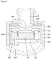
- FIG. 2 is a cross-sectional view of a receiver unit having a pressure equilibrium structure and a compensation structure for low frequency according to an embodiment of the present invention
- FIG. 3 is an exploded perspective view of a receiver unit having a pressure equilibrium structure and a compensation structure for low frequency according to an embodiment of the present invention.
- FIG. 4 is a graph showing comparison of sound pressure by frequency of a general canal-type earphone, a canal-type earphone having a receiver with a ventilation recess, and a canal-type earphone including a ventilation recess and a duct.
- FIG. 2 is a cross-sectional view of a receiver unit having a pressure equilibrium structure and a compensation structure for low frequency according to an embodiment of the present invention
- FIG. 3 is an exploded perspective view of a receiver unit having a pressure equilibrium structure and a compensation structure for low frequency according to an embodiment of the present invention.
- a receiver unit having a receiver unit having a pressure equilibrium structure and a compensation structure for low frequency includes a receiver 100 and an upper casing 200 and a lower casing 300 covering the receiver 100 .
- the receiver 100 having a general form, includes a frame, a magnetic circuit including a yoke and a permanent magnet, a voice coil vibrated by mutual electromagnetic force with the magnetic circuit, and a diaphragm 110 provided with the voice coil and generating a sound by vibration.
- the receiver 100 includes a back hole 120 allowing air outside the receiver 100 to flow to the lower space of the diaphragm 110 .
- the back hole 120 may be formed at a yoke or the frame according to a shape of the magnetic circuit structure or the frame of the receiver 100 .
- the upper casing 200 protects the receiver 100 and facilitates installation when installed in a housing 600 of an earphone.
- the upper casing 200 covers an upper portion of the receiver 100 and surrounds a side surface.
- the upper casing 200 is attached to the housing 600 by an adhesive 500 such as a double-sided tape.
- the receiver 100 is circular, so the upper casing 200 has a cylindrical shape.
- the housing 600 includes a sound tube 620 guiding sound into a user's ear and protruding to be inserted into the ear in case of a closed earphone.
- the upper casing 200 includes a sound insulation hole 210 corresponding to a position of the sound tube 620 so that a sound of the receiver 100 may be emitted to the sound tube 620 .
- the upper casing 200 has ventilation recesses 220 and 230 provided on an outer surface thereof to allow a lower space of the receiver unit and the sound tube 620 to communicate with each other to improve user inconvenience such as occurrence of deafening of the ear or the like due to a difference in pressure between an ear canal and inside/outside of the earphone as the earphone completely seals the ear canal.
- the ventilation recesses 220 and 230 include a first ventilation recess 220 extending from the sound insulation hole 210 to the side of the upper casing 200 , i.e., to an outer circumference, in the radial direction and formed in a horizontal direction and a second ventilation recess 230 communicating with the first ventilation recess 220 and extending in a vertical direction to have an overall length of the side surface of the upper casing 200 .
- a duct path 310 capable of improving low-frequency sound by generating resonance in the lower casing 300 is provided. Since the lower casing 300 is attached to the lower surface of the receiver 100 and an upper surface is closed by the receiver 100 , the duct path 310 may be formed by forming a recess on the upper surface of the lower casing 300 . An upper end of the duct path 310 communicates with the back hole 120 of the receiver 100 described above, and a lower end of the duct path 310 communicates with the lower space of the receiver unit in the earphone housing.
- the receiver unit may have an acoustic mesh.
- One or more acoustic meshes 510 and 520 may be provided in the duct path 310 .
- a first acoustic mesh 510 is attached to the receiver 100 to facilitate attachment and formed to cover the back hole 120 .
- the duct path 310 includes a receiving recess 320 with an end having a diameter larger than that of the first acoustic mesh 510 to accommodate the first acoustic mesh 510 .
- the second acoustic mesh 520 is attached to the lower surface of the lower casing 300 .
- the second acoustic mesh 520 is attached to cover the end of the duct path 310 .
- FIG. 4 is a graph showing comparison of sound pressure by frequency of a general canal-type earphone, a canal-type earphone having a receiver with a ventilation recess, and a canal-type earphone including a ventilation recess and a duct.
- the canal-type earphone has a high SPL in the low frequency region, but if a ventilation recess is provided in order to relieve deafening of the ear, large loss occurs in the SPL in the low frequency region.
- the ventilation recess and the duct are provided together as in the present invention, the SPL loss occurring in the low frequency region may be compensated to some extent.
Landscapes
- Physics & Mathematics (AREA)
- Engineering & Computer Science (AREA)
- Acoustics & Sound (AREA)
- Signal Processing (AREA)
- Health & Medical Sciences (AREA)
- Otolaryngology (AREA)
- Headphones And Earphones (AREA)
- Audible-Bandwidth Dynamoelectric Transducers Other Than Pickups (AREA)
Abstract
Description
Claims (5)
Applications Claiming Priority (3)
| Application Number | Priority Date | Filing Date | Title |
|---|---|---|---|
| KR1020190143349 | 2019-11-11 | ||
| KR1020190143349A KR102163268B1 (en) | 2019-11-11 | 2019-11-11 | Receiver unit having pressure equilibrium structre and compensation structure for low frequency |
| KR10-2019-0143349 | 2019-11-11 |
Publications (2)
| Publication Number | Publication Date |
|---|---|
| US20210144462A1 US20210144462A1 (en) | 2021-05-13 |
| US11368784B2 true US11368784B2 (en) | 2022-06-21 |
Family
ID=72897422
Family Applications (1)
| Application Number | Title | Priority Date | Filing Date |
|---|---|---|---|
| US17/094,090 Active US11368784B2 (en) | 2019-11-11 | 2020-11-10 | Receiver unit having pressure equilibrium structure and compensation structure for low frequency |
Country Status (2)
| Country | Link |
|---|---|
| US (1) | US11368784B2 (en) |
| KR (1) | KR102163268B1 (en) |
Cited By (1)
| Publication number | Priority date | Publication date | Assignee | Title |
|---|---|---|---|---|
| US20210329369A1 (en) * | 2018-11-14 | 2021-10-21 | Orfeo Soundworks Corporation | Earset having utterer voice restoration function |
Families Citing this family (7)
| Publication number | Priority date | Publication date | Assignee | Title |
|---|---|---|---|---|
| KR102097472B1 (en) * | 2019-07-18 | 2020-04-06 | 주식회사 비에스이 | Canal type earphone with pressure balanced structure |
| USD941274S1 (en) * | 2019-10-18 | 2022-01-18 | Bose Corporation | Ear tip |
| USD947156S1 (en) * | 2019-11-22 | 2022-03-29 | Bose Corporation | Ear tip |
| CN115696149A (en) * | 2021-07-30 | 2023-02-03 | 华为技术有限公司 | Double-diaphragm loudspeaker and electronic equipment |
| KR102577012B1 (en) * | 2022-03-16 | 2023-09-12 | 주식회사 이엠텍 | Receiver and earphone with it |
| KR102630054B1 (en) * | 2022-04-28 | 2024-01-25 | 엘지전자 주식회사 | Sound device |
| US11765496B1 (en) * | 2022-05-26 | 2023-09-19 | Merry Electronics(Shenzhen) Co., Ltd. | In-ear earphone |
Citations (11)
| Publication number | Priority date | Publication date | Assignee | Title |
|---|---|---|---|---|
| US6738487B1 (en) * | 1999-05-31 | 2004-05-18 | Sony Corporation | Earphone |
| US8111857B2 (en) * | 2005-09-16 | 2012-02-07 | Sennheiser Electronic Gmbh & Co. Kg | In-ear headset and in-ear earphone |
| US8885866B2 (en) * | 2011-07-22 | 2014-11-11 | Panasonic Corporation | Earphone |
| KR101558091B1 (en) | 2014-05-23 | 2015-10-06 | 부전전자 주식회사 | Canal type earphone with pressure equilibrium means |
| US9237394B2 (en) * | 2013-05-24 | 2016-01-12 | Bujeon Co., Ltd. | Canal type earphone with pressure equilibrium means |
| KR101958257B1 (en) | 2018-03-12 | 2019-07-02 | 부전전자 주식회사 | Earphone with pressure equilibrium means |
| US20190208301A1 (en) * | 2017-12-29 | 2019-07-04 | Knowles Electronics, Llc | Audio device with acoustic valve |
| US20200178003A1 (en) * | 2018-12-04 | 2020-06-04 | Sonova Ag | Hearing device with acoustically connected chambers and method of its operation |
| US20210099791A1 (en) * | 2019-09-26 | 2021-04-01 | Apple Inc. | Internal control leak integrated in a driver frame |
| US20210136478A1 (en) * | 2019-07-01 | 2021-05-06 | Merry Electronics(Shenzhen) Co., Ltd. | In-ear headphone |
| US20210289279A1 (en) * | 2020-03-16 | 2021-09-16 | Almus Corp. | Speaker unit for earphone |
-
2019
- 2019-11-11 KR KR1020190143349A patent/KR102163268B1/en active Active
-
2020
- 2020-11-10 US US17/094,090 patent/US11368784B2/en active Active
Patent Citations (11)
| Publication number | Priority date | Publication date | Assignee | Title |
|---|---|---|---|---|
| US6738487B1 (en) * | 1999-05-31 | 2004-05-18 | Sony Corporation | Earphone |
| US8111857B2 (en) * | 2005-09-16 | 2012-02-07 | Sennheiser Electronic Gmbh & Co. Kg | In-ear headset and in-ear earphone |
| US8885866B2 (en) * | 2011-07-22 | 2014-11-11 | Panasonic Corporation | Earphone |
| US9237394B2 (en) * | 2013-05-24 | 2016-01-12 | Bujeon Co., Ltd. | Canal type earphone with pressure equilibrium means |
| KR101558091B1 (en) | 2014-05-23 | 2015-10-06 | 부전전자 주식회사 | Canal type earphone with pressure equilibrium means |
| US20190208301A1 (en) * | 2017-12-29 | 2019-07-04 | Knowles Electronics, Llc | Audio device with acoustic valve |
| KR101958257B1 (en) | 2018-03-12 | 2019-07-02 | 부전전자 주식회사 | Earphone with pressure equilibrium means |
| US20200178003A1 (en) * | 2018-12-04 | 2020-06-04 | Sonova Ag | Hearing device with acoustically connected chambers and method of its operation |
| US20210136478A1 (en) * | 2019-07-01 | 2021-05-06 | Merry Electronics(Shenzhen) Co., Ltd. | In-ear headphone |
| US20210099791A1 (en) * | 2019-09-26 | 2021-04-01 | Apple Inc. | Internal control leak integrated in a driver frame |
| US20210289279A1 (en) * | 2020-03-16 | 2021-09-16 | Almus Corp. | Speaker unit for earphone |
Cited By (1)
| Publication number | Priority date | Publication date | Assignee | Title |
|---|---|---|---|---|
| US20210329369A1 (en) * | 2018-11-14 | 2021-10-21 | Orfeo Soundworks Corporation | Earset having utterer voice restoration function |
Also Published As
| Publication number | Publication date |
|---|---|
| US20210144462A1 (en) | 2021-05-13 |
| KR102163268B1 (en) | 2020-10-08 |
Similar Documents
| Publication | Publication Date | Title |
|---|---|---|
| US11368784B2 (en) | Receiver unit having pressure equilibrium structure and compensation structure for low frequency | |
| US11381898B2 (en) | Canal-type earphone having pressure equilibrium structure | |
| US11146876B2 (en) | Kernel-type earphone having pressure balance structure | |
| US9237394B2 (en) | Canal type earphone with pressure equilibrium means | |
| US11395060B2 (en) | Receiver having pressure equilibrium structure | |
| US11363370B2 (en) | Receiver module integrated with duct | |
| CN102196330B (en) | Earphone | |
| CN114697829B (en) | Bidirectional receiver with pre-bass conduit portion | |
| US11528563B2 (en) | Hybrid receiver having fixing bracket for drivers | |
| KR102442977B1 (en) | Hybrid receiver having fixing bracket for drivers | |
| US11336983B1 (en) | Receiver module having pressure equilibrium structure | |
| US10448147B2 (en) | Acoustic device having multiple diaphragms | |
| JP2018006784A (en) | Earphone | |
| US11564026B2 (en) | Earphone having pressure equilibrium structure | |
| JP5253075B2 (en) | Headphone unit and headphones | |
| US11206480B2 (en) | Open-air type earphone with bracket forming bass pipe | |
| KR102577024B1 (en) | Receiver having pressure equilibrium structure | |
| KR102238423B1 (en) | Receiver module with pressure equilibrium structure | |
| CN115134698B (en) | Receiver module with pressure balance structure | |
| KR102694789B1 (en) | A hybrid receiver having a barcket for driver installation | |
| KR20200091189A (en) | Acoustic device having multiple vibration plates |
Legal Events
| Date | Code | Title | Description |
|---|---|---|---|
| FEPP | Fee payment procedure |
Free format text: ENTITY STATUS SET TO UNDISCOUNTED (ORIGINAL EVENT CODE: BIG.); ENTITY STATUS OF PATENT OWNER: LARGE ENTITY |
|
| AS | Assignment |
Owner name: EM-TECH CO., LTD., KOREA, REPUBLIC OF Free format text: ASSIGNMENT OF ASSIGNORS INTEREST;ASSIGNOR:KIM, YONG HUE;REEL/FRAME:054440/0153 Effective date: 20201117 |
|
| STPP | Information on status: patent application and granting procedure in general |
Free format text: APPLICATION DISPATCHED FROM PREEXAM, NOT YET DOCKETED |
|
| STPP | Information on status: patent application and granting procedure in general |
Free format text: DOCKETED NEW CASE - READY FOR EXAMINATION |
|
| STPP | Information on status: patent application and granting procedure in general |
Free format text: NON FINAL ACTION MAILED |
|
| STPP | Information on status: patent application and granting procedure in general |
Free format text: RESPONSE TO NON-FINAL OFFICE ACTION ENTERED AND FORWARDED TO EXAMINER |
|
| STPP | Information on status: patent application and granting procedure in general |
Free format text: NOTICE OF ALLOWANCE MAILED -- APPLICATION RECEIVED IN OFFICE OF PUBLICATIONS |
|
| STPP | Information on status: patent application and granting procedure in general |
Free format text: PUBLICATIONS -- ISSUE FEE PAYMENT RECEIVED |
|
| STPP | Information on status: patent application and granting procedure in general |
Free format text: PUBLICATIONS -- ISSUE FEE PAYMENT VERIFIED |
|
| STCF | Information on status: patent grant |
Free format text: PATENTED CASE |
|
| FEPP | Fee payment procedure |
Free format text: MAINTENANCE FEE REMINDER MAILED (ORIGINAL EVENT CODE: REM.); ENTITY STATUS OF PATENT OWNER: LARGE ENTITY |