US11368687B2 - Method for decoding image by using block partitioning in image coding system, and device therefor - Google Patents
Method for decoding image by using block partitioning in image coding system, and device therefor Download PDFInfo
- Publication number
- US11368687B2 US11368687B2 US17/277,639 US201917277639A US11368687B2 US 11368687 B2 US11368687 B2 US 11368687B2 US 201917277639 A US201917277639 A US 201917277639A US 11368687 B2 US11368687 B2 US 11368687B2
- Authority
- US
- United States
- Prior art keywords
- block
- current block
- size
- flag
- partitioned
- Prior art date
- Legal status (The legal status is an assumption and is not a legal conclusion. Google has not performed a legal analysis and makes no representation as to the accuracy of the status listed.)
- Active
Links
- 238000000638 solvent extraction Methods 0.000 title claims abstract description 131
- 238000000034 method Methods 0.000 title claims abstract description 106
- 238000005192 partition Methods 0.000 claims abstract description 78
- 241000023320 Luma <angiosperm> Species 0.000 claims description 92
- OSWPMRLSEDHDFF-UHFFFAOYSA-N methyl salicylate Chemical compound COC(=O)C1=CC=CC=C1O OSWPMRLSEDHDFF-UHFFFAOYSA-N 0.000 claims description 92
- 239000000523 sample Substances 0.000 description 60
- 230000008569 process Effects 0.000 description 23
- 238000001914 filtration Methods 0.000 description 18
- 239000011449 brick Substances 0.000 description 10
- 238000002474 experimental method Methods 0.000 description 8
- 230000002123 temporal effect Effects 0.000 description 7
- 238000004891 communication Methods 0.000 description 6
- 238000010586 diagram Methods 0.000 description 6
- 238000012545 processing Methods 0.000 description 6
- 239000010751 BS 2869 Class A2 Substances 0.000 description 5
- 208000037170 Delayed Emergence from Anesthesia Diseases 0.000 description 4
- 230000003044 adaptive effect Effects 0.000 description 4
- 230000005540 biological transmission Effects 0.000 description 4
- 239000010754 BS 2869 Class F Substances 0.000 description 3
- 230000006835 compression Effects 0.000 description 3
- 238000007906 compression Methods 0.000 description 3
- 238000013139 quantization Methods 0.000 description 3
- 230000006978 adaptation Effects 0.000 description 2
- 230000002146 bilateral effect Effects 0.000 description 2
- 238000013507 mapping Methods 0.000 description 2
- 239000013074 reference sample Substances 0.000 description 2
- 230000007727 signaling mechanism Effects 0.000 description 2
- 238000012546 transfer Methods 0.000 description 2
- 241001025261 Neoraja caerulea Species 0.000 description 1
- 238000003491 array Methods 0.000 description 1
- 230000008901 benefit Effects 0.000 description 1
- 238000004590 computer program Methods 0.000 description 1
- 238000013500 data storage Methods 0.000 description 1
- 230000001419 dependent effect Effects 0.000 description 1
- 230000000694 effects Effects 0.000 description 1
- 238000005516 engineering process Methods 0.000 description 1
- 230000006870 function Effects 0.000 description 1
- 238000004519 manufacturing process Methods 0.000 description 1
- 238000010295 mobile communication Methods 0.000 description 1
- 230000003287 optical effect Effects 0.000 description 1
- 238000003672 processing method Methods 0.000 description 1
- 230000008707 rearrangement Effects 0.000 description 1
- 230000004044 response Effects 0.000 description 1
- 230000011664 signaling Effects 0.000 description 1
- 239000010454 slate Substances 0.000 description 1
- 239000004984 smart glass Substances 0.000 description 1
- 230000002194 synthesizing effect Effects 0.000 description 1
Images


Classifications
-
- H—ELECTRICITY
- H04—ELECTRIC COMMUNICATION TECHNIQUE
- H04N—PICTORIAL COMMUNICATION, e.g. TELEVISION
- H04N19/00—Methods or arrangements for coding, decoding, compressing or decompressing digital video signals
- H04N19/10—Methods or arrangements for coding, decoding, compressing or decompressing digital video signals using adaptive coding
- H04N19/134—Methods or arrangements for coding, decoding, compressing or decompressing digital video signals using adaptive coding characterised by the element, parameter or criterion affecting or controlling the adaptive coding
- H04N19/136—Incoming video signal characteristics or properties
-
- H—ELECTRICITY
- H04—ELECTRIC COMMUNICATION TECHNIQUE
- H04N—PICTORIAL COMMUNICATION, e.g. TELEVISION
- H04N19/00—Methods or arrangements for coding, decoding, compressing or decompressing digital video signals
- H04N19/10—Methods or arrangements for coding, decoding, compressing or decompressing digital video signals using adaptive coding
- H04N19/102—Methods or arrangements for coding, decoding, compressing or decompressing digital video signals using adaptive coding characterised by the element, parameter or selection affected or controlled by the adaptive coding
- H04N19/119—Adaptive subdivision aspects, e.g. subdivision of a picture into rectangular or non-rectangular coding blocks
-
- H—ELECTRICITY
- H04—ELECTRIC COMMUNICATION TECHNIQUE
- H04N—PICTORIAL COMMUNICATION, e.g. TELEVISION
- H04N19/00—Methods or arrangements for coding, decoding, compressing or decompressing digital video signals
- H04N19/10—Methods or arrangements for coding, decoding, compressing or decompressing digital video signals using adaptive coding
- H04N19/169—Methods or arrangements for coding, decoding, compressing or decompressing digital video signals using adaptive coding characterised by the coding unit, i.e. the structural portion or semantic portion of the video signal being the object or the subject of the adaptive coding
- H04N19/17—Methods or arrangements for coding, decoding, compressing or decompressing digital video signals using adaptive coding characterised by the coding unit, i.e. the structural portion or semantic portion of the video signal being the object or the subject of the adaptive coding the unit being an image region, e.g. an object
- H04N19/176—Methods or arrangements for coding, decoding, compressing or decompressing digital video signals using adaptive coding characterised by the coding unit, i.e. the structural portion or semantic portion of the video signal being the object or the subject of the adaptive coding the unit being an image region, e.g. an object the region being a block, e.g. a macroblock
-
- H—ELECTRICITY
- H04—ELECTRIC COMMUNICATION TECHNIQUE
- H04N—PICTORIAL COMMUNICATION, e.g. TELEVISION
- H04N19/00—Methods or arrangements for coding, decoding, compressing or decompressing digital video signals
- H04N19/10—Methods or arrangements for coding, decoding, compressing or decompressing digital video signals using adaptive coding
- H04N19/169—Methods or arrangements for coding, decoding, compressing or decompressing digital video signals using adaptive coding characterised by the coding unit, i.e. the structural portion or semantic portion of the video signal being the object or the subject of the adaptive coding
- H04N19/186—Methods or arrangements for coding, decoding, compressing or decompressing digital video signals using adaptive coding characterised by the coding unit, i.e. the structural portion or semantic portion of the video signal being the object or the subject of the adaptive coding the unit being a colour or a chrominance component
-
- H—ELECTRICITY
- H04—ELECTRIC COMMUNICATION TECHNIQUE
- H04N—PICTORIAL COMMUNICATION, e.g. TELEVISION
- H04N19/00—Methods or arrangements for coding, decoding, compressing or decompressing digital video signals
- H04N19/70—Methods or arrangements for coding, decoding, compressing or decompressing digital video signals characterised by syntax aspects related to video coding, e.g. related to compression standards
Definitions
- the present disclosure relates to a video coding technology, and more particularly, to a video decoding method using block partitioning in a video coding system and an apparatus thereof.
- HD High Definition
- UHD Ultra High Definition
- the present disclosure provides a method and device for improving image coding efficiency.
- the present disclosure also provides a method and device for improving intra-prediction efficiency.
- the present disclosure also provides a method and device for improving intra-prediction efficiency based on cross component linear model (CCLM).
- CCLM cross component linear model
- the present disclosure also provides an efficient encoding and decoding method for CCLM prediction, and a device for performing the encoding and decoding method.
- the present disclosure also provides a method and device for selecting a neighbor sample to derive a linear model parameter for CCLM.
- a video decoding method performed by a decoding apparatus includes: obtaining image information including partitioning information; determining whether a current block is partitioned based on a size of the current block; and decoding the current block or decoding sub-blocks of the current block based on whether the determined current block is partitioned, wherein when it is determined that the current block is partitioned, the current block is partitioned into the sub-blocks based on the partitioning information, and the sub-blocks are decoded, wherein when it is determined that the current block is not partitioned, the current block is not partitioned, and the current block is decoded, and wherein when the current block is a chroma block and the size of the current block is less than or equal to a minimum chroma block size, it is determined that the current block is not partitioned.
- a decoding apparatus for performing video decoding.
- the device apparatus includes: an entropy decoder obtaining image information including partitioning information; and a predictor determining whether a current block is partitioned based on a size of the current block and decoding the current block or decoding sub-blocks of the current block based on whether the determined current block is partitioned, wherein when it is determined that the current block is partitioned, the current block is partitioned into the sub-blocks based on the partitioning information, and the sub-blocks are decoded, wherein when it is determined that the current block is not partitioned, the current block is not partitioned, and the current block is decoded, and wherein when the current block is a chroma block and the size of the current block is less than or equal to a minimum chroma block size, it is determined that the current block is not partitioned.
- a video encoding method performed by an encoding apparatus includes: determining a partition type for a current block; determining whether to partition the current block based on a size of the current block; not partitioning the current block if the current block is determined not to be partitioned and partitioning the current block into sub-blocks based on the partition type if the current block is determined to be partitioned; and encoding image information including partitioning information indicating the partition type for the current block, wherein when the current block is a chroma block and the size of the current block is less than or equal to a minimum chroma block size, it is determined that the current block is not partitioned.
- a video encoding apparatus includes: an image partitioner determining a partition type for a current block, determining whether to partition the current block based on a size of the current block, not partitioning the current block if the current block is determined not to be partitioned and partitioning the current block into sub-blocks based on the partition type if the current block is determined to be partitioned; and an entropy encoder encoding image information including partitioning information indicating the partition type for the current block, wherein when the current block is a chroma block and the size of the current block is less than or equal to a minimum chroma block size, it is determined that the current block is not partitioned.
- image coding efficiency may be improved by effectively performing image partitioning.
- FIG. 1 briefly illustrates an example of a video/image coding device to which embodiments of the present disclosure are applicable.
- FIG. 2 is a schematic diagram illustrating a configuration of a video/image encoding apparatus to which the embodiment(s) of the present disclosure may be applied.
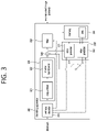
- FIG. 3 is a schematic diagram illustrating a configuration of a video/image decoding apparatus to which the embodiment(s) of the present disclosure may be applied.
- FIG. 4 shows an example of partitioning a block through a QT structure.
- FIG. 5 shows an example of partitioning a block through a BT structure.
- FIG. 6 shows an example of partitioning a block through a TT structure.
- FIG. 7 exemplarily shows a signaling mechanism of partitioning information.
- FIG. 8 exemplarily shows a partition type in an MTT structure.
- FIG. 9 exemplarily shows an embodiment in which partitioning into a 4 ⁇ 4 size luma block and a 2 ⁇ 2 size chroma block is prohibited when a size of an input image is FHD or larger.
- FIG. 10 exemplarily shows an embodiment in which a minimum block size is adjusted based on a size of an input image.
- FIG. 11 exemplarily shows an embodiment of adjusting a minimum block size.
- FIG. 12 exemplarily shows an embodiment of determining a minimum block size based on signaled minimum block size information.
- FIG. 13 schematically shows an image encoding method by an encoding apparatus according to the present disclosure.
- FIG. 14 schematically shows an encoding apparatus that performs an image encoding method according to the present disclosure.
- FIG. 15 schematically shows an image decoding method by a decoding apparatus according to the present disclosure.
- FIG. 16 schematically shows a decoding apparatus for performing an image decoding method according to the present disclosure.
- FIG. 17 exemplarily shows a structure diagram of a content streaming system to which embodiments of the present disclosure are applied.
- elements in the drawings described in the disclosure are independently drawn for the purpose of convenience for explanation of different specific functions, and do not mean that the elements are embodied by independent hardware or independent software.
- two or more elements of the elements may be combined to form a single element, or one element may be partitioned into plural elements.
- the embodiments in which the elements are combined and/or partitioned belong to the disclosure without departing from the concept of the disclosure.
- FIG. 1 briefly illustrates an example of a video/image coding device to which embodiments of the present disclosure are applicable.
- a video/image coding system may include a first device (source device) and a second device (receiving device).
- the source device may deliver encoded video/image information or data in the form of a file or streaming to the receiving device via a digital storage medium or network.
- the source device may include a video source, an encoding apparatus, and a transmitter.
- the receiving device may include a receiver, a decoding apparatus, and a renderer.
- the encoding apparatus may be called a video/image encoding apparatus, and the decoding apparatus may be called a video/image decoding apparatus.
- the transmitter may be included in the encoding apparatus.
- the receiver may be included in the decoding apparatus.
- the renderer may include a display, and the display may be configured as a separate device or an external component.
- the video source may acquire video/image through a process of capturing, synthesizing, or generating the video/image.
- the video source may include a video/image capture device and/or a video/image generating device.
- the video/image capture device may include, for example, one or more cameras, video/image archives including previously captured video/images, and the like.
- the video/image generating device may include, for example, computers, tablets and smartphones, and may (electronically) generate video/images.
- a virtual video/image may be generated through a computer or the like. In this case, the video/image capturing process may be replaced by a process of generating related data.
- the encoding apparatus may encode input image/image.
- the encoding apparatus may perform a series of procedures such as prediction, transform, and quantization for compression and coding efficiency.
- the encoded data (encoded video/image information) may be output in the form of a bitstream.
- the transmitter may transmit the encoded image/image information or data output in the form of a bitstream to the receiver of the receiving device through a digital storage medium or a network in the form of a file or streaming.
- the digital storage medium may include various storage mediums such as USB, SD, CD, DVD, Blu-ray, HDD, SSD, and the like.
- the transmitter may include an element for generating a media file through a predetermined file format and may include an element for transmission through a broadcast/communication network.
- the receiver may receive/extract the bitstream and transmit the received bitstream to the decoding apparatus.
- the decoding apparatus may decode the video/image by performing a series of procedures such as dequantization, inverse transform, and prediction corresponding to the operation of the encoding apparatus.
- the renderer may render the decoded video/image.
- the rendered video/image may be displayed through the display.
- Present disclosure relates to video/image coding.
- the methods/embodiments disclosed in the present disclosure may be applied to a method disclosed in the versatile video coding (VVC), the EVC (essential video coding) standard, the AOMedia Video 1 (AV1) standard, the 2nd generation of audio video coding standard (AVS2), or the next generation video/image coding standard (ex. H.267 or H.268, etc.).
- VVC versatile video coding
- EVC essential video coding
- AV1 AOMedia Video 1
- AVS2 2nd generation of audio video coding standard
- next generation video/image coding standard ex. H.267 or H.268, etc.
- Present disclosure presents various embodiments of video/image coding, and the embodiments may be performed in combination with each other unless otherwise mentioned.
- video may refer to a series of images over time.
- Picture generally refers to a unit representing one image in a specific time zone, and a slice/tile is a unit constituting part of a picture in coding.
- the slice/tile may include one or more coding tree units (CTUs).
- CTUs coding tree units
- One picture may consist of one or more slices/tiles.
- One picture may consist of one or more tile groups.
- One tile group may include one or more tiles.
- a brick may represent a rectangular region of CTU rows within a tile in a picture.
- a tile may be partitioned into multiple bricks, each of which consisting of one or more CTU rows within the tile.
- a tile that is not partitioned into multiple bricks may be also referred to as a brick.
- a brick scan is a specific sequential ordering of CTUs partitioning a picture in which the CTUs are ordered consecutively in CTU raster scan in a brick, bricks within a tile are ordered consecutively in a raster scan of the bricks of the tile, and tiles in a picture are ordered consecutively in a raster scan of the tiles of the picture.
- a tile is a rectangular region of CTUs within a particular tile column and a particular tile row in a picture.
- the tile column is a rectangular region of CTUs having a height equal to the height of the picture and a width specified by syntax elements in the picture parameter set.
- the tile row is a rectangular region of CTUs having a height specified by syntax elements in the picture parameter set and a width equal to the width of the picture.
- a tile scan is a specific sequential ordering of CTUs partitioning a picture in which the CTUs are ordered consecutively in CTU raster scan in a tile whereas tiles in a picture are ordered consecutively in a raster scan of the tiles of the picture.
- a slice includes an integer number of bricks of a picture that may be exclusively contained in a single NAL unit.
- a slice may consists of either a number of complete tiles or only a consecutive sequence of complete bricks of one tile.
- Tile groups and slices may be used interchangeably in the present disclosure. For example, in the present disclosure, a tile group/tile group header may be called a slice/slice header.
- a pixel or a pel may mean a smallest unit constituting one picture (or image). Also, ‘sample’ may be used as a term corresponding to a pixel.
- a sample may generally represent a pixel or a value of a pixel, and may represent only a pixel/pixel value of a luma component or only a pixel/pixel value of a chroma component.
- a unit may represent a basic unit of image processing.
- the unit may include at least one of a specific region of the picture and information related to the region.
- One unit may include one luma block and two chroma (ex. cb, cr) blocks.
- the unit may be used interchangeably with terms such as block or area in some cases.
- an M ⁇ N block may include samples (or sample arrays) or a set (or array) of transform coefficients of M columns and N rows.
- the term “/” and “,” should be interpreted to indicate “and/or.”
- the expression “A/B” may mean “A and/or B.”
- “A, B” may mean “A and/or B.”
- “A/B/C” may mean “at least one of A, B, and/or C.”
- “A/B/C” may mean “at least one of A, B, and/or C.”
- the term “or” should be interpreted to indicate “and/or.”
- the expression “A or B” may comprise 1) only A, 2) only B, and/or 3) both A and B.
- the term “or” in the present disclosure should be interpreted to indicate “additionally or alternatively.”
- FIG. 2 is a schematic diagram illustrating a configuration of a video/image encoding apparatus to which the embodiment(s) of the present disclosure may be applied.
- the video encoding apparatus may include an image encoding apparatus.
- the encoding apparatus 200 includes an image partitioner 210 , a predictor 220 , a residual processor 230 , and an entropy encoder 240 , an adder 250 , a filter 260 , and a memory 270 .
- the predictor 220 may include an inter predictor 221 and an intra predictor 222 .
- the residual processor 230 may include a transformer 232 , a quantizer 233 , a dequantizer 234 , and an inverse transformer 235 .
- the residual processor 230 may further include a subtractor 231 .
- the adder 250 may be called a reconstructor or a reconstructed block generator.
- the image partitioner 210 , the predictor 220 , the residual processor 230 , the entropy encoder 240 , the adder 250 , and the filter 260 may be configured by at least one hardware component (ex. An encoder chipset or processor) according to an embodiment.
- the memory 270 may include a decoded picture buffer (DPB) or may be configured by a digital storage medium.
- the hardware component may further include the memory 270 as an internal/external component.
- the image partitioner 210 may partition an input image (or a picture or a frame) input to the encoding apparatus 200 into one or more processors.
- the processor may be called a coding unit (CU).
- the coding unit may be recursively partitioned according to a quad-tree binary-tree ternary-tree (QTBTTT) structure from a coding tree unit (CTU) or a largest coding unit (LCU).
- QTBTTT quad-tree binary-tree ternary-tree
- CTU coding tree unit
- LCU largest coding unit
- one coding unit may be partitioned into a plurality of coding units of a deeper depth based on a quad tree structure, a binary tree structure, and/or a ternary structure.
- the quad tree structure may be applied first and the binary tree structure and/or ternary structure may be applied later.
- the binary tree structure may be applied first.
- the coding procedure according to the present disclosure may be performed based on the final coding unit that is no longer partitioned.
- the largest coding unit may be used as the final coding unit based on coding efficiency according to image characteristics, or if necessary, the coding unit may be recursively partitioned into coding units of deeper depth and a coding unit having an optimal size may be used as the final coding unit.
- the coding procedure may include a procedure of prediction, transform, and reconstruction, which will be described later.
- the processor may further include a prediction unit (PU) or a transform unit (TU).
- the prediction unit and the transform unit may be split or partitioned from the aforementioned final coding unit.
- the prediction unit may be a unit of sample prediction
- the transform unit may be a unit for deriving a transform coefficient and/or a unit for deriving a residual signal from the transform coefficient.
- an M ⁇ N block may represent a set of samples or transform coefficients composed of M columns and N rows.
- a sample may generally represent a pixel or a value of a pixel, may represent only a pixel/pixel value of a luma component or represent only a pixel/pixel value of a chroma component.
- a sample may be used as a term corresponding to one picture (or image) for a pixel or a pel.
- a prediction signal (predicted block, prediction sample array) output from the inter predictor 221 or the intra predictor 222 is subtracted from an input image signal (original block, original sample array) to generate a residual signal residual block, residual sample array), and the generated residual signal is transmitted to the transformer 232 .
- a unit for subtracting a prediction signal (predicted block, prediction sample array) from the input image signal (original block, original sample array) in the encoder 200 may be called a subtractor 231 .
- the predictor may perform prediction on a block to be processed (hereinafter, referred to as a current block) and generate a predicted block including prediction samples for the current block.
- the predictor may determine whether intra prediction or inter prediction is applied on a current block or CU basis. As described later in the description of each prediction mode, the predictor may generate various information related to prediction, such as prediction mode information, and transmit the generated information to the entropy encoder 240 .
- the information on the prediction may be encoded in the entropy encoder 240 and output in the form of a bitstream.
- the intra predictor 222 may predict the current block by referring to the samples in the current picture.
- the referred samples may be located in the neighborhood of the current block or may be located apart according to the prediction mode.
- prediction modes may include a plurality of non-directional modes and a plurality of directional modes.
- the non-directional mode may include, for example, a DC mode and a planar mode.
- the directional mode may include, for example, 33 directional prediction modes or 65 directional prediction modes according to the degree of detail of the prediction direction. However, this is merely an example, more or less directional prediction modes may be used depending on a setting.
- the intra predictor 222 may determine the prediction mode applied to the current block by using a prediction mode applied to a neighboring block.
- the inter predictor 221 may derive a predicted block for the current block based on a reference block (reference sample array) specified by a motion vector on a reference picture.
- the motion information may be predicted in units of blocks, sub-blocks, or samples based on correlation of motion information between the neighboring block and the current block.
- the motion information may include a motion vector and a reference picture index.
- the motion information may further include inter prediction direction (L0 prediction, L1 prediction, Bi prediction, etc.) information.
- the neighboring block may include a spatial neighboring block present in the current picture and a temporal neighboring block present in the reference picture.
- the reference picture including the reference block and the reference picture including the temporal neighboring block may be the same or different.
- the temporal neighboring block may be called a collocated reference block, a co-located CU (colCU), and the like, and the reference picture including the temporal neighboring block may be called a collocated picture (colPic).
- the inter predictor 221 may configure a motion information candidate list based on neighboring blocks and generate information indicating which candidate is used to derive a motion vector and/or a reference picture index of the current block. Inter prediction may be performed based on various prediction modes. For example, in the case of a skip mode and a merge mode, the inter predictor 221 may use motion information of the neighboring block as motion information of the current block.
- the residual signal may not be transmitted.
- the motion vector of the neighboring block may be used as a motion vector predictor and the motion vector of the current block may be indicated by signaling a motion vector difference.
- the predictor 220 may generate a prediction signal based on various prediction methods described below.
- the predictor may not only apply intra prediction or inter prediction to predict one block but also simultaneously apply both intra prediction and inter prediction. This may be called combined inter and intra prediction (CIIP).
- the predictor may be based on an intra block copy (IBC) prediction mode or a palette mode for prediction of a block.
- the IBC prediction mode or palette mode may be used for content image/video coding of a game or the like, for example, screen content coding (SCC).
- SCC screen content coding
- the IBC basically performs prediction in the current picture but may be performed similarly to inter prediction in that a reference block is derived in the current picture. That is, the IBC may use at least one of the inter prediction techniques described in the present disclosure.
- the palette mode may be considered as an example of intra coding or intra prediction. When the palette mode is applied, a sample value within a picture may be signaled based on information on the palette table and the palette index.
- the prediction signal generated by the predictor may be used to generate a reconstructed signal or to generate a residual signal.
- the transformer 232 may generate transform coefficients by applying a transform technique to the residual signal.
- the transform technique may include at least one of a discrete cosine transform (DCT), a discrete sine transform (DST), a karhunen-loève transform (KLT), a graph-based transform (GBT), or a conditionally non-linear transform (CNT).
- the GBT means transform obtained from a graph when relationship information between pixels is represented by the graph.
- the CNT refers to transform generated based on a prediction signal generated using all previously reconstructed pixels.
- the transform process may be applied to square pixel blocks having the same size or may be applied to blocks having a variable size rather than square.
- the quantizer 233 may quantize the transform coefficients and transmit them to the entropy encoder 240 and the entropy encoder 240 may encode the quantized signal (information on the quantized transform coefficients) and output a bitstream.
- the information on the quantized transform coefficients may be referred to as residual information.
- the quantizer 233 may rearrange block type quantized transform coefficients into a one-dimensional vector form based on a coefficient scanning order and generate information on the quantized transform coefficients based on the quantized transform coefficients in the one-dimensional vector form. Information on transform coefficients may be generated.
- the entropy encoder 240 may perform various encoding methods such as, for example, exponential Golomb, context-adaptive variable length coding (CAVLC), context-adaptive binary arithmetic coding (CABAC), and the like.
- the entropy encoder 240 may encode information necessary for video/image reconstruction other than quantized transform coefficients (ex. values of syntax elements, etc.) together or separately.
- Encoded information (ex. encoded video/image information) may be transmitted or stored in units of NALs (network abstraction layer) in the form of a bitstream.
- the video/image information may further include information on various parameter sets such as an adaptation parameter set (APS), a picture parameter set (PPS), a sequence parameter set (SPS), or a video parameter set (VPS).
- APS adaptation parameter set
- PPS picture parameter set
- SPS sequence parameter set
- VPS video parameter set
- the video/image information may further include general constraint information.
- information and/or syntax elements transmitted/signaled from the encoding apparatus to the decoding apparatus may be included in video/picture information.
- the video/image information may be encoded through the above-described encoding procedure and included in the bitstream.
- the bitstream may be transmitted over a network or may be stored in a digital storage medium.
- the network may include a broadcasting network and/or a communication network
- the digital storage medium may include various storage media such as USB, SD, CD, DVD, Blu-ray, HDD, SSD, and the like.
- a transmitter (not shown) transmitting a signal output from the entropy encoder 240 and/or a storage unit (not shown) storing the signal may be included as internal/external element of the encoding apparatus 200 , and alternatively, the transmitter may be included in the entropy encoder 240 .
- the quantized transform coefficients output from the quantizer 233 may be used to generate a prediction signal.
- the residual signal residual block or residual samples
- the adder 250 adds the reconstructed residual signal to the prediction signal output from the inter predictor 221 or the intra predictor 222 to generate a reconstructed signal (reconstructed picture, reconstructed block, reconstructed sample array). If there is no residual for the block to be processed, such as a case where the skip mode is applied, the predicted block may be used as the reconstructed block.
- the adder 250 may be called a reconstructor or a reconstructed block generator.
- the generated reconstructed signal may be used for intra prediction of a next block to be processed in the current picture and may be used for inter prediction of a next picture through filtering as described below.
- LMCS luma mapping with chroma scaling
- the filter 260 may improve subjective/objective image quality by applying filtering to the reconstructed signal.
- the filter 260 may generate a modified reconstructed picture by applying various filtering methods to the reconstructed picture and store the modified reconstructed picture in the memory 270 , specifically, a DPB of the memory 270 .
- the various filtering methods may include, for example, deblocking filtering, a sample adaptive offset, an adaptive loop filter, a bilateral filter, and the like.
- the filter 260 may generate various information related to the filtering and transmit the generated information to the entropy encoder 240 as described later in the description of each filtering method.
- the information related to the filtering may be encoded by the entropy encoder 240 and output in the form of a bitstream.
- the modified reconstructed picture transmitted to the memory 270 may be used as the reference picture in the inter predictor 221 .
- the inter prediction is applied through the encoding apparatus, prediction mismatch between the encoding apparatus 200 and the decoding apparatus may be avoided and encoding efficiency may be improved.
- the DPB of the memory 270 DPB may store the modified reconstructed picture for use as a reference picture in the inter predictor 221 .
- the memory 270 may store the motion information of the block from which the motion information in the current picture is derived (or encoded) and/or the motion information of the blocks in the picture that have already been reconstructed.
- the stored motion information may be transmitted to the inter predictor 221 and used as the motion information of the spatial neighboring block or the motion information of the temporal neighboring block.
- the memory 270 may store reconstructed samples of reconstructed blocks in the current picture and may transfer the reconstructed samples to the intra predictor 222 .
- FIG. 3 is a schematic diagram illustrating a configuration of a video/image decoding apparatus to which the embodiment(s) of the present disclosure may be applied.
- the decoding apparatus 300 may include an entropy decoder 310 , a residual processor 320 , a predictor 330 , an adder 340 , a filter 350 , a memory 360 .
- the predictor 330 may include an inter predictor 331 and an intra predictor 332 .
- the residual processor 320 may include a dequantizer 321 and an inverse transformer 321 .
- the entropy decoder 310 , the residual processor 320 , the predictor 330 , the adder 340 , and the filter 350 may be configured by a hardware component (ex. A decoder chipset or a processor) according to an embodiment.
- the memory 360 may include a decoded picture buffer (DPB) or may be configured by a digital storage medium.
- the hardware component may further include the memory 360 as an internal/external component.
- the decoding apparatus 300 may reconstruct an image corresponding to a process in which the video/image information is processed in the encoding apparatus of FIG. 2 .
- the decoding apparatus 300 may derive units/blocks based on block partition related information obtained from the bitstream. That is, the image partitioner of the decoding apparatus 300 may partition an input image (or picture, frame) into one or more processing units.
- the decoding apparatus 300 may perform decoding using a processor applied in the encoding apparatus.
- the processor of decoding may be a coding unit, for example, and the coding unit may be partitioned according to a quad tree structure, binary tree structure and/or ternary tree structure from the coding tree unit or the largest coding unit.
- One or more transform units may be derived from the coding unit.
- the reconstructed image signal decoded and output through the decoding apparatus 300 may be reproduced through a reproducing apparatus.
- the decoding apparatus 300 may receive a signal output from the encoding apparatus of FIG. 2 in the form of a bitstream, and the received signal may be decoded through the entropy decoder 310 .
- the entropy decoder 310 may parse the bitstream to derive information (ex. video/image information) necessary for image reconstruction (or picture reconstruction).
- the video/image information may further include information on various parameter sets such as an adaptation parameter set (APS), a picture parameter set (PPS), a sequence parameter set (SPS), or a video parameter set (VPS).
- the video/image information may further include general constraint information.
- the decoding apparatus may further decode picture based on the information on the parameter set and/or the general constraint information.
- Signaled/received information and/or syntax elements described later in the present disclosure may be decoded may decode the decoding procedure and obtained from the bitstream.
- the entropy decoder 310 decodes the information in the bitstream based on a coding method such as exponential Golomb coding, CAVLC, or CABAC, and output syntax elements required for image reconstruction and quantized values of transform coefficients for residual.
- the CABAC entropy decoding method may receive a bin corresponding to each syntax element in the bitstream, determine a context model using a decoding target syntax element information, decoding information of a decoding target block or information of a symbol/bin decoded in a previous stage, and perform an arithmetic decoding on the bin by predicting a probability of occurrence of a bin according to the determined context model, and generate a symbol corresponding to the value of each syntax element.
- the CABAC entropy decoding method may update the context model by using the information of the decoded symbol/bin for a context model of a next symbol/bin after determining the context model.
- the information related to the prediction among the information decoded by the entropy decoder 310 may be provided to the predictor (the inter predictor 332 and the intra predictor 331 ), and the residual value on which the entropy decoding was performed in the entropy decoder 310 , that is, the quantized transform coefficients and related parameter information, may be input to the residual processor 320 .
- the residual processor 320 may derive the residual signal (the residual block, the residual samples, the residual sample array).
- information on filtering among information decoded by the entropy decoder 310 may be provided to the filter 350 .
- a receiver for receiving a signal output from the encoding apparatus may be further configured as an internal/external element of the decoding apparatus 300 , or the receiver may be a component of the entropy decoder 310 .
- the decoding apparatus according to the present disclosure may be referred to as a video/image/picture decoding apparatus, and the decoding apparatus may be classified into an information decoder (video/image/picture information decoder) and a sample decoder (video/image/picture sample decoder).
- the information decoder may include the entropy decoder 310 , and the sample decoder may include at least one of the dequantizer 321 , the inverse transformer 322 , the adder 340 , the filter 350 , the memory 360 , the inter predictor 332 , and the intra predictor 331 .
- the dequantizer 321 may dequantize the quantized transform coefficients and output the transform coefficients.
- the dequantizer 321 may rearrange the quantized transform coefficients in the form of a two-dimensional block form. In this case, the rearrangement may be performed based on the coefficient scanning order performed in the encoding apparatus.
- the dequantizer 321 may perform dequantization on the quantized transform coefficients by using a quantization parameter (ex. quantization step size information) and obtain transform coefficients.
- the inverse transformer 322 inversely transforms the transform coefficients to obtain a residual signal (residual block, residual sample array).
- the predictor may perform prediction on the current block and generate a predicted block including prediction samples for the current block.
- the predictor may determine whether intra prediction or inter prediction is applied to the current block based on the information on the prediction output from the entropy decoder 310 and may determine a specific intra/inter prediction mode.
- the predictor 320 may generate a prediction signal based on various prediction methods described below. For example, the predictor may not only apply intra prediction or inter prediction to predict one block but also simultaneously apply intra prediction and inter prediction. This may be called combined inter and intra prediction (CIIP).
- the predictor may be based on an intra block copy (IBC) prediction mode or a palette mode for prediction of a block.
- the IBC prediction mode or palette mode may be used for content image/video coding of a game or the like, for example, screen content coding (SCC).
- SCC screen content coding
- the IBC basically performs prediction in the current picture but may be performed similarly to inter prediction in that a reference block is derived in the current picture. That is, the IBC may use at least one of the inter prediction techniques described in the present disclosure.
- the palette mode may be considered as an example of intra coding or intra prediction. When the palette mode is applied, a sample value within a picture may be signaled based on information on the palette table and the palette index.
- the intra predictor 331 may predict the current block by referring to the samples in the current picture.
- the referred samples may be located in the neighborhood of the current block or may be located apart according to the prediction mode.
- prediction modes may include a plurality of non-directional modes and a plurality of directional modes.
- the intra predictor 331 may determine the prediction mode applied to the current block by using a prediction mode applied to a neighboring block.
- the inter predictor 332 may derive a predicted block for the current block based on a reference block (reference sample array) specified by a motion vector on a reference picture.
- motion information may be predicted in units of blocks, sub-blocks, or samples based on correlation of motion information between the neighboring block and the current block.
- the motion information may include a motion vector and a reference picture index.
- the motion information may further include inter prediction direction (L0 prediction, L1 prediction, Bi prediction, etc.) information.
- the neighboring block may include a spatial neighboring block present in the current picture and a temporal neighboring block present in the reference picture.
- the inter predictor 332 may configure a motion information candidate list based on neighboring blocks and derive a motion vector of the current block and/or a reference picture index based on the received candidate selection information.
- Inter prediction may be performed based on various prediction modes, and the information on the prediction may include information indicating a mode of inter prediction for the current block.
- the adder 340 may generate a reconstructed signal (reconstructed picture, reconstructed block, reconstructed sample array) by adding the obtained residual signal to the prediction signal (predicted block, predicted sample array) output from the predictor (including the inter predictor 332 and/or the intra predictor 331 ). If there is no residual for the block to be processed, such as when the skip mode is applied, the predicted block may be used as the reconstructed block.
- the adder 340 may be called reconstructor or a reconstructed block generator.
- the generated reconstructed signal may be used for intra prediction of a next block to be processed in the current picture, may be output through filtering as described below, or may be used for inter prediction of a next picture.
- LMCS luma mapping with chroma scaling
- the filter 350 may improve subjective/objective image quality by applying filtering to the reconstructed signal.
- the filter 350 may generate a modified reconstructed picture by applying various filtering methods to the reconstructed picture and store the modified reconstructed picture in the memory 360 , specifically, a DPB of the memory 360 .
- the various filtering methods may include, for example, deblocking filtering, a sample adaptive offset, an adaptive loop filter, a bilateral filter, and the like.
- the (modified) reconstructed picture stored in the DPB of the memory 360 may be used as a reference picture in the inter predictor 332 .
- the memory 360 may store the motion information of the block from which the motion information in the current picture is derived (or decoded) and/or the motion information of the blocks in the picture that have already been reconstructed.
- the stored motion information may be transmitted to the inter predictor 260 so as to be utilized as the motion information of the spatial neighboring block or the motion information of the temporal neighboring block.
- the memory 360 may store reconstructed samples of reconstructed blocks in the current picture and transfer the reconstructed samples to the intra predictor 331 .
- the embodiments described in the filter 260 , the inter predictor 221 , and the intra predictor 222 of the encoding apparatus 200 may be the same as or respectively applied to correspond to the filter 350 , the inter predictor 332 , and the intra predictor 331 of the decoding apparatus 300 . The same may also apply to the unit 332 and the intra predictor 331 .
- encoding target images of the VVC standard are high-resolution images such as UHD and FHD, and hardware is increasingly complicated to process the images.
- VTM2.0.1 a 128 ⁇ 128-sized coding tree unit (CTU) is used, but a minimum CU block size is 4 ⁇ 4 size for luma blocks and 2 ⁇ 2 size for chroma blocks. Therefore, when an UHD image (3840 ⁇ 2160 resolution) is encoded by performing intra prediction through the VTM2.0.1 software, in a worst case scenario, the UHD image may be partitioned into 518,400 4 ⁇ 4 luma blocks and 1,036,800 2 ⁇ 2 chroma blocks.
- CTU 128 ⁇ 128-sized coding tree unit
- the worst case may represent a case in which all of the luma components of the UHD image are encoded into 4 ⁇ 4-sized luma blocks, and all of the chroma components are encoded into 2 ⁇ 2-sized chroma blocks.
- data throughput should cover the worst case, which may lead to an increase in hardware manufacturing cost and hardware delay.
- the present disclosure proposes embodiments for solving the above-described problem.
- a method of solving complexity of hardware implementation is proposed by adaptively adjusting the minimum block size according to a size of an image size (i.e., resolution). That is, in the present disclosure, an embodiment in which data throughput in the worst case is adjusted by adaptively adjusting the minimum block size according to a size of an image to control the amount of data throughput in the worst case is proposed.
- the block may represent a coding unit (CU), a prediction unit (PU), or a transform unit (TU).
- experimental results for an image in which a 4 ⁇ 4-sized luma block and a 2 ⁇ 2-sized chroma block are limited on the VTM2.0.1 software may be derived as shown in the following table. That is, the experiment may represent coding of an image in which the minimum size of the luma block is 4 ⁇ 8 size/8 ⁇ 4 size and the minimum size of the chroma block is 2 ⁇ 4 size/4 ⁇ 2 size. In addition, the following table may show experimental results for images of all resolutions.
- encoding loss of Y 0.46% in the all intra experiment, Y 0.36% in a random access experiment, and Y 0.29% in a low delay B experiment. may be derived.
- the worst case data throughput may be halved and the encoding and decoding processing rate may be reduced.
- the present embodiment proposes a method of adaptively adjusting a minimum block size as follows.
- the QT structure, the BT structure, and the TT structure may be described later.
- FIG. 4 shows an example of partitioning a block through the QT structure.
- the QT structure may represent a structure in which a block having a size of 2N ⁇ 2N is partitioned into four sub-blocks having a size of N ⁇ N.
- block A may be partitioned into four square sub-blocks (block A 0 , block A 1 , block A 2 , and block A 3 ) according to the QT structure.
- the partitioned block may be partitioned into blocks of a lower depth recursively by the QT structure.
- the sub-block A 1 may be partitioned into four sub-blocks (block B 0 , block B 1 , block B 2 , and block B 3 ) according to the QT structure.
- FIG. 5 shows an example of partitioning a block through the BT structure.
- the BT structure may represent a structure in which a W ⁇ H-sized block is partitioned into two (W/2) ⁇ H-sized sub-blocks or two W ⁇ (H/2)-sized sub-blocks.
- the structure in which the W ⁇ H-sized block is partitioned into two (W/2) ⁇ H-sized sub-blocks may be expressed as a vertical BT structure, and the structure in which the W ⁇ H-sized block is partitioned into two W ⁇ (H/2)-sized sub-blocks may be referred to as a horizontal BT structure.
- a block B 3 that is no longer partitioned by a QT structure may be partitioned into a sub-block C 0 and a sub-block C 1 by a vertical BT structure, or may be partitioned into a sub-block D 0 and a sub-block D 1 by a horizontal BT structure.
- each sub-block may be further partitioned into a horizontal BT structure (e.g., sub-block E 0 , sub-block E 1 ) or a vertical BT structure (e.g., sub-block F 0 , sub-block F 1 ) recursively.
- FIG. 6 shows an example of partitioning a block through the TT structure.
- the TT structure may represent a structure in which a W ⁇ H-sized block is partitioned into two (W/4) ⁇ H-sized sub-blocks and (W/2) ⁇ H-sized sub-blocks, or two W ⁇ (H/4)-sized sub-blocks and W ⁇ (H/2)-sized sub-blocks.
- a (W/2) ⁇ H-sized sub-block or W ⁇ (H/2)-sized sub-block may be a central sub-block.
- the structure in which the W ⁇ H-sized block is partitioned into two (W/4) ⁇ H-sized sub-blocks and (W/2) ⁇ H-sized sub-blocks may be represented as a vertical TT structure
- the structure in which the W ⁇ H-sized block is partitioned into two W ⁇ (H/4)-sized sub-blocks and W ⁇ (H/2)-sized sub-blocks may be represented as a horizontal TT structure.
- a block B 3 that is no longer partitioned by a QT structure may be partitioned into a sub-block C 0 , a sub-block C 1 , and a sub-block C 2 by a vertical TT structure, or partitioned into D 0 , sub-block D 1 , and sub-block D 2 by a horizontal TT structure.
- each sub-block may be further partitioned recursively through a horizontal TT structure (e.g., partitioned into sub-block E 0 , sub-block E 1 , sub-block E 2 ) or vertical TT structure (e.g., sub-block F 0 , sub-block F 1 , and sub-block F 2 ).
- horizontal TT structure e.g., partitioned into sub-block E 0 , sub-block E 1 , sub-block E 2
- vertical TT structure e.g., sub-block F 0 , sub-block F 1 , and sub-block F 2 .
- the current block may be recursively partitioned according to a quad-tree binary-tree ternary-tree (QTBTTT) structure.
- QTBTTT quad-tree binary-tree ternary-tree
- the current block may be partitioned into a plurality of coding units of a deeper depth based on a quad tree structure, a binary tree structure, and/or a ternary structure.
- the QTBTTT structure may also be referred to as a multi-type tree (MTT) structure.
- the current block may be partitioned according to the MTT structure based on signaled partitioning information.
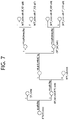
- FIG. 7 exemplarily shows a signaling mechanism of partitioning information.
- a CTU may be treated as a root of a QT, and thus, the CTU may be initially partitioned into the QT structure. Thereafter, each QT leaf node (CU which is no longer partitioned into the QT structure) may be further partitioned into an MTT structure afterwards.
- a first flag e.g., MTT split CU flag (mtt_split_cu_flag)
- mtt_split_cu_flag MTT split CU flag
- a second flag e.g., MTT split CU vertical flag (mtt_split_cu_vertical_flag)
- MTT split CU vertical flag mtt_split_cu_vertical_flag
- a third flag e.g., MTT split CU binary flag (mtt_split_cu_binary_flag)
- MttSplitMode multi-type tree partitioning mode of a corresponding CU derived based on the second flag and the third flag may be derived as shown in the following.
- SPLIT_TT_HOR, SPLIT_BT_HOR, SPLIT_TT_VER, and SPLIT_BT_VER may represent a partition type (or a multi-type tree partition mode).
- SPLIT_TT_HOR may represent a horizontal ternary type
- SPLIT_BT_HOR may represent a horizontal binary type
- SPLIT_TT_VER may represent a vertical ternary type
- SPLIT_TT_VER may represent a vertical binary type.
- the partition type of the corresponding CU when the value of the second flag is 0 and the value of the third flag is 0, the partition type of the corresponding CU may be derived as the horizontal ternary type, when the value of the second flag is 0 and the value of the third flag is 1, the partition type of the CU may be derived as the horizontal binary type, when the value of the second flag is 1 and the value of the third flag is 0, the partition type of the corresponding CU may be derived as the vertical ternary type, and when the value of the second flag is 1 and the value of the third flag is 1, the partition type of the corresponding CU may be derived as the vertical binary type.
- FIG. 8 exemplarily shows a partition type in an MTT structure.
- the horizontal ternary type may be a type in which a block is partitioned into two W ⁇ (H/4)-sized sub-blocks and W ⁇ (H/2)-sized sub-blocks, in which the W ⁇ (H/2)-sized sub-block of is a central sub-block.
- the vertical ternary may represent a type in which a block is partitioned into two (W/4) ⁇ H-sized sub-blocks and (W/2) ⁇ H-sized sub-blocks, in which the (W/2) ⁇ H-sized sub-block is a central sub-block. Also, referring to FIG.
- the horizontal binary type may represent a type in which a block is partitioned into two W ⁇ (H/2)-sized sub-blocks
- the vertical binary type may represent a type in which a block is partitioned into two (W/2) ⁇ H-sized sub-blocks.
- FIG. 9 exemplarily shows an embodiment in which partitioning into a 4 ⁇ 4-sized luma block and a 2 ⁇ 2-sized chroma block is prohibited when the size of an input image is greater than or equal to FHD.
- the encoding apparatus/decoding apparatus may determine whether the number of samples (or the number of pixels) of the current image is 1920 ⁇ 1080 or higher (S 900 ).
- the encoding apparatus/decoding apparatus may determine whether the number of samples of the block generated by partitioning the current block into a QT structure, a BT structure, or a TT structure is greater than a specific number (S 910 ).
- the encoding apparatus/decoding apparatus may determine whether the number of samples of the generated blocks by partitioning is greater than 16, and when the current block is a current chroma block, the encoding apparatus/decoding apparatus may determine whether the number of samples of the generated blocks by partitioning is greater than 4.
- the specific number may be represented as a threshold value.
- the encoding apparatus/decoding apparatus may check the existing QT/BT.TT partitioning condition for the current block and perform partitioning on the current block. (S 920 ).
- the encoding apparatus/decoding apparatus may not perform partitioning on the current block (S 930 ).
- the encoding apparatus/decoding apparatus may check the existing QT/BT.TT partitioning condition for the current block without the determination process of step S 910 , and then perform partitioning on the current block (S 920 ).
- a minimum block size is adaptively determined by partitioning an image size (i.e., resolution) may be proposed.
- the above embodiment is as follows.
- the following conditions may be applied when determining whether to QT/BT/TT partition a block.
- the current chroma block becomes a 2 ⁇ 2-sized, 2 ⁇ 4-sized, or 4 ⁇ 2-sized after QT, horizontal BT, vertical BT, horizontal TT or vertical TT partitioning, the corresponding partitioning is prohibited.
- FIG. 10 exemplarily shows an embodiment in which a minimum block size is adjusted based on a size of an input image.
- the encoding apparatus/decoding apparatus may determine whether the number of samples (or the number of pixels) of the current image is 1920 ⁇ 1080 or higher (S 1000 ).
- the encoding apparatus/decoding apparatus may determine whether the number of samples (or the number of pixels) of the current image is 3840 ⁇ 2160 or greater (S 1010 ).
- the encoding apparatus/decoding apparatus may set a threshold value for the current block (S 1020 ).
- the threshold value for the current luma block may be set to 32, and the threshold value for the current chroma block may be set to 8.
- the encoding apparatus/decoding apparatus may set a threshold value for the current block (S 1030 ). In this case, a threshold value for the current luma block may be set to 16 and a threshold value for the current chroma block may be set to 4.
- the encoding apparatus/decoding apparatus may determine whether the number of samples of the blocks generated by partitioning the current block into a QT structure, a BT structure, or a TT structure is greater than the set threshold value (S 1040 ).
- the encoding apparatus/decoding apparatus may check the existing QT/BT.TT partitioning condition for the current block and perform the partitioning on the current block (S 1050 ).
- the encoding apparatus/decoding apparatus may not partition partitioning on the current block (S 1060 ).
- the encoding apparatus/decoding apparatus may check the existing QT/BT.TT partitioning condition for the current block without the determination process of steps S 1010 to S 1040 , and perform partitioning on the current block (S 1050 ).
- the following conditions may be applied when determining whether a block is partitioned into QT/BT/TT.
- FIG. 11 exemplarily shows an embodiment of adjusting the minimum block size.
- the encoding apparatus/decoding apparatus may determine whether the number of samples of a block generated by partitioning a current block into a QT structure, a BT structure, or a TT structure is greater than a threshold value (S 1100 ).
- the encoding apparatus/decoding apparatus may determine whether the number of divided and generated samples of the block is greater than 16, and when the current block is a current chroma block, the encoding apparatus/decoding apparatus may determine whether the number of partitioned and generated samples of the block is greater than 4. That is, the threshold value for the current luma block may be set to 16, and the threshold value for the current chroma block may be set to 4.
- the encoding apparatus/decoding apparatus may determine whether the number of samples of the current block is 32 or less, and when the current block is a current chroma block, the encoding apparatus/decoding apparatus may determine whether the number of samples in the current block is 8 or less. That is, the threshold value for the current luma block may be set to 32, and the threshold value for the current chroma block may be set to 8.
- the current block when it is partitioned according to the BT structure, it is partitioned into sub-blocks including half the number of samples of the current block, and thus, a value of double of the threshold value of the number of the partitioned and generated samples of the block may be compared with the current block and determined.
- the current block when the current block is partitioned, when the current block is partitioned according to the QT structure or the TT structure, it is partitioned into sub-blocks including a sample number of 1 ⁇ 4 of the number of samples of the current block, and thus, a value that is four times the threshold of the number of partitioned and generated samples of the block may be compared with the current block and determined.
- the encoding apparatus/decoding apparatus may check the existing QT/BT.TT partitioning conditions for the current block and perform partitioning on the current block (S 1110 ).
- the encoding apparatus/decoding apparatus may not perform partitioning on the current block (S 1120 ).
- the following conditions may be applied.
- the encoding apparatus/decoding apparatus may determine whether the number of samples of a block generated by partitioning the current chroma block into a QT structure, a BT structure, or a TT structure is greater than a threshold value (e.g., 4).
- a threshold value e.g. 4
- the threshold value for the current chroma block may be set to 4.
- the encoding apparatus/decoding apparatus may check the existing QT/BT.TT partitioning condition for the current chroma block and perform partitioning on the current chroma block.
- the encoding apparatus/decoding apparatus may not partition partitioning on the current chroma block.
- Another embodiment may be proposed in which the problem of complexity and high cost in hardware implementation may be solved by adjusting the minimum block size. That is, another embodiment may be proposed in which the data throughput in the worst case is adjusted by adaptively adjusting the minimum block size.
- the present embodiment proposes a method of transmitting minimum block size information by a high level syntax (HLS) such as a sequence parameter set (SPS), a picture parameter set (PPS), or a slice header.
- HLS high level syntax
- SPS sequence parameter set
- PPS picture parameter set
- slice header a slice header
- the minimum block size information in the SPS may be represented as shown in the table below. That is, the minimum block size information signaled by the SPS may be as shown in the following table.
- the minimum block size information may include minimum luma block size information and/or minimum chroma block size information.
- the minimum luma block size information may represent a minimum luma block size
- the minimum chroma block size information may represent a minimum chroma block size.
- log 2_min_cu_pixel_num_luma_minus4 and log 2_min_cu_pixel_num_chroma_minus2 may be included in the SPS.
- the log 2_min_cu_pixel_num_luma_minus4 may indicate a syntax element of the minimum luma block size information
- the log 2_min_cu_pixel_num_chroma_minus2 may indicate a syntax element of the minimum chroma block size information.
- the decoding apparatus may limit the minimum block size based on the log 2_min_cu_pixel_num_luma_minus4 and the log 2_min_cu_pixel_num_chroma_minus2.
- a minimum number of samples of the luma block represented by log 2_min_cu_pixel_num_luma_minus4 is 16 (for example, log 2_num_num_2 ⁇ 4 size)
- the minimum number of samples of the indicated chroma block may be 4 (e.g., 2 ⁇ 2 size). Therefore, the minimum block size limitation may not be performed.
- the decoding apparatus may limit the size of a 4 ⁇ 4-sized luma block and a 2 ⁇ 2-sized chroma block. That is, the decoding apparatus may limit partitioning into a 4 ⁇ 4-sized luma block and a 2 ⁇ 2-sized chroma block.
- the decoding apparatus may not limit the minimum luma block size.
- the decoding apparatus may limit chroma block sizes of 2 ⁇ 2, 2 ⁇ 4, and 4 ⁇ 2 sizes. That is, the decoding apparatus may limit partitioning into 2 ⁇ 2, 2 ⁇ 4, and 4 ⁇ 2-sized chroma blocks.
- FIG. 12 exemplarily shows an embodiment of determining a minimum block size based on signaled minimum block size information.
- the encoding apparatus/decoding apparatus may determine whether the current block is a luma block (S 1200 ). That is, the encoding apparatus/decoding apparatus may determine whether the current block is a current luma block or a current chroma block.
- the encoding apparatus/decoding apparatus may set a threshold value for the current luma block based on log 2_min_cu_pixel_num_luma_minus4 (S 1210 ). For example, the threshold value for the current luma block may be set to 16 ⁇ log 2_min_cu_pixel_num_luma_minus4.
- the encoding apparatus/decoding apparatus may set a threshold value for the current chroma block based on the log 2_min_cu_pixel_num_chroma_minus2 (S 1220 ). For example, the threshold value for the current chroma block may be set to 4 ⁇ log 2_min_cu_pixel_num_chroma_minus2.
- the encoding apparatus/decoding apparatus may determine whether the number of samples of the block generated by partitioning the current block into a QT structure, a BT structure, or a TT structure is greater than the set threshold value (S 1230 ).
- the encoding apparatus/decoding apparatus may check the existing QT/BT.TT partitioning condition for the current block and perform partitioning on the current block (S 1240 ).
- the encoding apparatus/decoding apparatus may not perform partitioning on the current block (S 1250 ).
- the encoding apparatus may perform encoding by setting the values of log 2_min_cu_pixel_num_luma_minus4 and log 2_min_cu_pixel_num_chroma_minus2 and transmit the information through SPS.
- the encoding apparatus may perform encoding after performing the minimum block size limitation based on the set log 2_min_cu_pixel_num_luma_minus4 and log 2_min_cu_pixel_num_chroma_minus2.
- log 2_min_cu_pixel_num_luma_minus4 and log 2_min_cu_pixel_num_chroma_minus2 may be set according to the image size as in the previous embodiment, or the value may be directly set at the time of encoding and encoding may be performed.
- FIG. 13 schematically shows a video encoding method by an encoding apparatus according to the present disclosure.
- the method disclosed in FIG. 13 may be performed by the encoding apparatus disclosed in FIG. 2 .
- steps S 1300 to S 1320 of FIG. 13 may be performed by the image partitioner of the encoding apparatus, and S 1330 may be performed by the entropy encoder of the encoding apparatus.
- a process of deriving a residual sample for the current block (or a sub-block of the current block) based on the original sample and a predicted sample for the current block (or a sub-block of the current block) may be performed by the subtractor of the encoding apparatus, a process of deriving reconstructed samples for the current block (or sub-block of the current block) based on the residual samples for the current block (or sub-block of the current block) and prediction samples may be performed by the adder of the encoding apparatus, and a process of generating information on residual for the current block (or a sub-block of the current block) based on the residual sample may be performed by the transformer of the encoding apparatus, and a process of encoding the information on the residual may be performed by the entropy encoder of the encoding apparatus.
- the encoding apparatus determines a partition type for the current block (S 1300 ).
- the encoding apparatus may partition an input image (or picture, frame) into one or more processing units.
- the current block may be recursively partitioned according to a QTBTTT (quad-tree binary-tree ternary-tree) structure from a coding tree unit (CTU) or a largest coding unit (LCU).
- the current block may be partitioned into a plurality of sub-blocks based on a QT (Qaud-Tree) type, a horizontal binary type, a horizontal ternary type, a vertical binary type, and/or a vertical ternary type.
- the encoding apparatus may determine the partition type for the current block as one of the QT (Qaud-Tree) type, the horizontal binary type, the horizontal ternary type, the vertical binary type, and the vertical ternary type.
- the encoding apparatus determines whether to partition the current block based on a size of the current block (S 1310 ).
- the encoding apparatus may determine whether to partition the current block based on the size of the current block.
- the size of the current block may represent the number of samples of the current block.
- the size of the current block may represent a width or height of the current block.
- the partition type of the current block is a vertical binary type or a vertical ternary type
- the size of the current block may be a width of the current block
- the partition type of the current block is a horizontal binary type or a horizontal ternary type
- the size of the current block may be a height of the current block.
- the current block when the current block is a chroma block and a size of the current block is less than or equal to the minimum chroma block size, it may be determined that the current block is not partitioned. In addition, when the current block is a chroma block and a size of the current block is larger than the minimum chroma block size, it may be determined that the current block is partitioned.
- the current block is the chroma block and the size of a sub-block partitioned and derived from the current block is 2 ⁇ 2, it may be determined that the current block is not partitioned.
- the current block when the current block is a luma block and the size of the current block is less than or equal to the minimum luma block size, it may be determined that the current block is not partitioned. In addition, when the current block is a luma block and a size of the current block is larger than the minimum luma block size, it may be determined that the current block is partitioned.
- the current block is the luma block and a size of the sub-block partitioned and derived from the current block is 4 ⁇ 4, it may be determined that the current block is not partitioned.
- the minimum chroma block size may be derived as follows.
- the minimum chroma block size may be derived as a preset value.
- the minimum chroma block size may be 8, 16 or 32.
- the minimum chroma block size may be derived based on information indicating the minimum chroma block size.
- the encoding apparatus may determine the minimum chroma block size, and generate and encode information indicating the minimum chroma block size, and the minimum chroma block size may be derived based on information indicating the minimum chroma block size.
- the minimum chroma block size may be derived as 8, 16, or 32 based on information indicating the minimum chroma block size.
- the minimum luma block size may be derived as follows.
- the minimum luma block size may be derived as a preset value.
- the minimum luma block size may be 16, 32, or 64.
- the minimum luma block size may be derived based on information indicating the minimum luma block size.
- the encoding apparatus may determine the minimum luma block size, and generate and encode information indicating the minimum luma block size, and the minimum luma block size may be derived based on the information indicating the minimum chroma block size.
- the minimum luma block size may be derived as 16, 32, or 64 based on the information indicating the minimum luma block size.
- the encoding apparatus When it is determined that the current block is not partitioned, the encoding apparatus does not partition the current block, and when it is determined that the current block is partitioned, the encoding apparatus partitions the current block into sub-blocks based on the partition type (S 1320 ).
- the encoding apparatus may partition the current block into the sub-blocks according to the partition type.
- the partition type may be one of the QT (Qaud-Tree) type, the horizontal binary type, the horizontal ternary type, the vertical binary type, and the vertical ternary type.
- the QT type may indicate a type in which a block is partitioned into four (W/2) ⁇ (H/2)-sized sub-blocks.
- W may denote a width of the current block
- H may be a height of the current block.
- the horizontal ternary type may indicate a type in which a block is partitioned into two W ⁇ (H/4)-sized sub-blocks and W ⁇ (H/2)-sized sub-blocks in which the W ⁇ (H/2)-sized sub-block is a center sub-block.
- the vertical ternary type may indicate a type in which a block is partitioned into two (W/4) ⁇ H-sized sub-blocks and (W/2) ⁇ H-sized sub-blocks in which the (W/2) ⁇ H-sized sub-block is a central sub-block.
- Block-in type may be indicated.
- the horizontal binary type may indicate a type in which a block is partitioned into two W ⁇ (H/2)-sized sub-blocks
- the vertical binary type may indicate a type in which a block is partitioned into two (W/2) ⁇ H-sized sub-blocks.
- the encoding apparatus may encode the sub-blocks.
- the encoding apparatus may perform prediction on sub-blocks, generate predicted blocks including prediction samples for the sub-blocks, and generate and encode prediction related information for sub-blocks.
- the image information may include the prediction related information.
- the encoding apparatus may determine whether intra prediction or inter prediction is applied to each of the sub-blocks, and may determine a specific intra/inter prediction mode for each sub-block. Next, the encoding apparatus may generate prediction samples based on various prediction methods described above.
- the encoding apparatus may derive residual samples for the sub-blocks based on the original samples and prediction samples for the sub-blocks, generate Information on the residual for the sub-blocks based on the residual samples, and encode the information on the residual.
- the image information may include the information on the residual.
- the encoding apparatus may generate reconstructed samples for the sub-blocks based on the prediction samples and the residual samples for the sub-blocks.
- the encoding apparatus may decode the current block.
- the encoding apparatus may perform prediction on the current block and generate a predicted block including a prediction sample for the current block, and generate and encode prediction related information on the current block.
- the image information may include the prediction related information.
- the encoding apparatus may determine whether intra prediction or inter prediction is applied to the current block, and may determine a specific intra/inter prediction mode for the current block. Next, the encoding apparatus may generate a prediction sample based on various prediction methods described above.
- the encoding apparatus may derive a residual sample for the current block based on the original sample and the predicted sample for the current block, generate information on residual for the current block based on the residual sample, and encode the information on the residual. Also, the encoding apparatus may generate a reconstructed sample for the current block based on the prediction sample and the residual sample for the current block.
- the encoding apparatus encodes image information including partitioning information indicating a partition type for the current block (S 1330 ).
- the encoding apparatus may encode image information including partitioning information indicating a partition type for the current block and signal the information through a bitstream.
- the partitioning information may include a first flag indicating whether the current block is partitioned into a QT (Quad-Tree) type or not.
- the QT type may indicate a partition type in which the current block is partitioned into four (W/2) ⁇ (H/2)-sized sub-blocks. W may denote a width of the current block, and H may denote a height of the current block.
- the partitioning information may include a second flag and a third flag.
- the second flag may indicate a partitioning direction of the current block
- the third flag may indicate whether the partition type of the current block is a binary-tree (BT) type or a tertiary-tree (TT) type.
- a syntax element indicating the first flag may be split_qt_flag
- a syntax element indicating the second flag may be mtt_split_cu_vertical_flag
- a syntax element indicating the third flag may be mtt_split_cu_binary_flag.
- the image information may include information indicating a minimum luma block size.
- the information indicating the minimum luma block size may be signaled in units of a coding unit (CU), a slice header, a picture parameter set (PPS), or a sequence parameter set (SPS). That is, the information indicating the minimum luma block size may be signaled as a coding unit (CU), a slice header, a picture parameter set (PPS), or a sequence parameter set (SPS).
- the image information may include information indicating a minimum chroma block size.
- the information indicating the minimum chroma block size may be signaled in units of a coding unit (CU), a slice header, a picture parameter set (PPS), or a sequence parameter set (SPS).
- the information indicating the minimum luma block size may be signaled as a coding unit (CU), a slice header, a picture parameter set (PPS), or a sequence parameter set (SPS).
- a syntax element indicating information indicating the minimum luma block size may be log 2_min_cu_pixel_num_luma_minus4, and a syntax element indicating information indicating the minimum chroma block size may be log 2_min_cu_pixel_num_chroma_minus2.
- the image information may include prediction related information on the current block or the sub-blocks.
- the prediction related information may indicate information on inter prediction or intra prediction applied to the current block or the sub-blocks.
- the image information may include information on a residual for the current block or the sub-blocks.
- the bitstream may be transmitted to a decoding apparatus through a network or a (digital) storage medium.
- the network may include a broadcasting network and/or a communication network
- the digital storage medium may include various storage media such as USB, SD, CD, DVD, Blu-ray, HDD, and SSD.
- FIG. 14 schematically shows an encoding apparatus that performs an image encoding method according to the present disclosure.
- the method disclosed in FIG. 13 may be performed by the encoding apparatus disclosed in FIG. 14 .
- the image partitioner of the encoding apparatus of FIG. 14 may perform S 1300 to S 1320 of FIG. 13
- the entropy encoder of the encoding apparatus of FIG. 14 may perform S 1330 of FIG. 13 .
- the process of deriving a residual sample for the current block (or a sub-block of the current block) based on the original sample and the predicted sample for the current block (or a sub-block of the current block) may be performed by the subtractor of the encoding apparatus of FIG.
- the process of deriving a reconstructed sample for the current block (or a sub-block of the current block) based on a prediction sample and a residual sample for the current block (or a sub-block of the current block) may be performed by the adder of the encoding apparatus of FIG. 14 , and the process of generating information on the residual for the current block (or a sub-block of the current block) based on the residual sample may be performed by the transformer of the encoding apparatus of FIG. 14 , and the process of encoding the information on the residual may be performed by the entropy encoder of the encoding apparatus of FIG. 14 .
- FIG. 15 schematically shows a video decoding method by the decoding apparatus according to the present disclosure.
- the method disclosed in FIG. 15 may be performed by the decoding apparatus disclosed in FIG. 3 .
- S 1500 of FIG. 15 may be performed by the entropy decoder of the decoding apparatus, and steps S 1510 and S 1520 may be performed by the image partitioner, the predictor, and the adder of the decoding apparatus.
- the process of acquiring information on the residual of the current block through the bitstream may be performed by the entropy decoder of the decoding apparatus, and the process of deriving the residual sample for the current block based on the residual information may be performed by an inverse transformer of the decoding apparatus.
- the decoding apparatus obtains image information including partitioning information (S 1500 ).
- the decoding apparatus may obtain the image information including the partitioning information through a bitstream.
- the partitioning information may include a first flag indicating whether the current block is partitioned into a QT (Quad-Tree) type or not.
- the QT type may indicate a partition type in which the current block is partitioned into four (W/2) ⁇ (H/2)-sized sub-blocks. W may denote a width of the current block, and H may denote a height of the current block.
- the partitioning information may include a second flag and a third flag.
- the second flag may indicate a partitioning direction of the current block
- the third flag may indicate whether the partition type of the current block is a binary-tree (BT) type or a tertiary-tree (TT) type.
- a syntax element indicating the first flag may be split_qt_flag
- a syntax element indicating the second flag may be mtt_split_cu_vertical_flag
- a syntax element indicating the third flag may be mtt_split_cu_binary_flag.
- the image information may include information indicating a minimum luma block size.
- the information indicating the minimum luma block size may be signaled in units of a coding unit (CU), a slice header, a picture parameter set (PPS), or a sequence parameter set (SPS). That is, the information indicating the minimum luma block size may be signaled as a coding unit (CU), a slice header, a picture parameter set (PPS), or a sequence parameter set (SPS).
- the image information may include information indicating a minimum chroma block size.
- the information indicating the minimum chroma block size may be signaled in units of a coding unit (CU), a slice header, a picture parameter set (PPS), or a sequence parameter set (SPS).
- the information indicating the minimum luma block size may be signaled as a coding unit (CU), a slice header, a picture parameter set (PPS), or a sequence parameter set (SPS).
- a syntax element indicating information indicating the minimum luma block size may be log 2_min_cu_pixel_num_luma_minus4, and a syntax element indicating information indicating the minimum chroma block size may be log 2_min_cu_pixel_num_chroma_minus2.
- the image information may include prediction related information on the current block or the sub-blocks.
- the prediction related information may indicate information on inter prediction or intra prediction applied to the current block or the sub-blocks.
- the decoding apparatus determines whether to partition the current block based on a size of the current block (S 1510 ).
- the decoding apparatus may determine whether to partition the current block based on the size of the current block.
- the size of the current block may represent the number of samples of the current block. Alternatively, the size of the current block may represent a width or height of the current block. For example, when the partition type of the current block is a vertical binary type or a vertical ternary type, the size of the current block may be a width of the current block, and when the partition type of the current block is a horizontal binary type or a horizontal ternary type, the size of the current block may be a height of the current block.
- the current block when the current block is a chroma block and a size of the current block is less than or equal to the minimum chroma block size, it may be determined that the current block is not partitioned. In addition, when the current block is a chroma block and a size of the current block is larger than the minimum chroma block size, it may be determined that the current block is partitioned.
- the current block is the chroma block and the size of a sub-block partitioned and derived from the current block is 2 ⁇ 2, it may be determined that the current block is not partitioned.
- the current block when the current block is a luma block and the size of the current block is less than or equal to the minimum luma block size, it may be determined that the current block is not partitioned. In addition, when the current block is a luma block and a size of the current block is larger than the minimum luma block size, it may be determined that the current block is partitioned.
- the current block is the luma block and a size of the sub-block partitioned and derived from the current block is 4 ⁇ 4, it may be determined that the current block is not partitioned.
- the minimum chroma block size may be derived as follows.
- the minimum chroma block size may be derived as a preset value.
- the minimum chroma block size may be 8, 16 or 32.
- the minimum chroma block size may be derived based on the information indicating the minimum chroma block size.
- the minimum chroma block size may be derived as 8, 16 or 32 based on the information indicating the minimum chroma block size.
- the minimum luma block size may be derived as follows.
- the minimum luma block size may be derived as a preset value.
- the minimum luma block size may be 16, 32, or 64.
- the minimum luma block size may be derived based on the information indicating the minimum luma block size.
- the minimum luma block size may be derived as 16, 32, or 64 based on the information indicating the minimum luma block size.
- the decoding apparatus decodes the current block or sub-blocks of the current block based on whether to determine the current block as determined (S 1520 ).
- the decoding apparatus may partition the current block into sub-blocks based on the partitioning information, and decode the sub-blocks.
- the decoding apparatus may derive a partition type for the current block based on the partitioning information, and partition the current block into sub-blocks according to the partition type.
- the partitioning information may include a first flag.
- the decoding apparatus may partition the current block into the sub-blocks according to the QT type.
- the QT type may represent a type in which a block is partitioned into four (W/2) ⁇ (H/2)-sized sub-blocks.
- W may denote a width of the current block
- H may be a height of the current block.
- the decoding apparatus may partition the current block into sub-blocks through the partition type of the current block derived based on the second flag and the third flag.
- the partition type derived based on the first flag and the third flag may be one of a horizontal ternary type, a horizontal binary type, a vertical ternary type, and a vertical binary type.
- the partition type may be derived as the horizontal ternary type.
- the partition type may be derived as the horizontal binary type.
- the partition type When the value of the second flag is 1 and the value of the third flag is 0, the partition type may be derived as the vertical ternary type, and when the value of the second flag is 1 and the value of the third flag is 1, the partition type may be derived as the vertical binary type.
- the horizontal ternary type may be a type in which a block is partitioned into two W ⁇ (H/4)-sized sub-blocks and W ⁇ (H/2)-sized sub-blocks, in which the W ⁇ (H/2)-sized sub-block of is a central sub-block.
- the vertical ternary may represent a type in which a block is partitioned into two (W/4) ⁇ H-sized sub-blocks and (W/2) ⁇ H-sized sub-blocks, in which the (W/2) ⁇ H-sized sub-block is a central sub-block.
- the horizontal binary type may represent a type in which a block is partitioned into two W ⁇ (H/2)-sized sub-blocks
- the vertical binary type may represent a type in which a block is partitioned into two (W/2) ⁇ H-sized sub-blocks.
- the decoding apparatus may decode the sub-blocks.
- the decoding apparatus may perform prediction on the sub-blocks and generate predicted blocks including prediction samples for the sub-blocks.
- the decoding apparatus may determine whether intra prediction or inter prediction is applied to each of the sub-blocks based on the prediction related information, and may determine a specific intra/inter prediction mode for each sub-block.
- the decoding apparatus may generate prediction samples based on various prediction methods described above.
- the decoding apparatus may generate reconstructed samples based on the prediction samples.
- the decoding apparatus may receive information on residual for the sub-blocks from the bitstream.
- the information on the residual may include a transform coefficient on the residual sample.
- the decoding apparatus may derive the residual samples (or residual sample array) for the sub-blocks based on the information on the residual.
- the decoding apparatus may generate the reconstructed samples based on the prediction samples and the residual samples.
- the decoding apparatus may derive a reconstructed block or a reconstructed picture based on the reconstructed sample. Thereafter, as described above, the decoding apparatus may apply an in-loop filtering procedure such as deblocking filtering and/or SAO procedure to the reconstructed picture in order to improve subjective/objective image quality as needed.
- the decoding apparatus may decode the current block without partitioning the current block.
- the decoding apparatus may perform prediction on the current block and generate a predicted block including a prediction sample for the current block.
- the decoding apparatus may determine whether intra prediction or inter prediction is applied to the current block based on the prediction related information and may determine a specific intra/inter prediction mode for the current block.
- the decoding apparatus may generate a prediction sample based on various prediction methods described above.
- the decoding apparatus may generate a reconstructed sample based on the prediction sample.
- the decoding apparatus may receive information on the residual for the current block from the bitstream.
- the information on the residual may include a transform coefficient on the residual sample.
- the decoding apparatus may derive the residual sample (or residual sample array) for the current block based on the information on the residual.
- the decoding apparatus may generate the reconstructed sample based on the prediction sample and the residual sample.
- the decoding apparatus may derive a reconstructed block or a reconstructed picture based on the reconstructed sample.
- the decoding apparatus may apply an in-loop filtering procedure such as deblocking filtering and/or SAO procedure to the reconstructed picture in order to improve subjective/objective image quality as needed.
- FIG. 16 schematically shows a decoding apparatus for performing a video decoding method according to the present disclosure.
- the method disclosed in FIG. 15 may be performed by the decoding apparatus disclosed in FIG. 16 .
- the entropy decoder of the decoding apparatus of FIG. 16 may perform S 1500 of FIG. 15
- the image partitioner, the predictor, and the adder of the decoding apparatus of FIG. 16 may perform steps S 1510 and S 1520 of FIG. 15 .
- the process of acquiring image information including the information on the residual of the current block through the bitstream may be performed by the entropy decoder of the decoding apparatus of FIG. 16 .
- the process of deriving the residual samples for the current block based on the information on the residual may be performed by the inverse transformer of the decoding apparatus of FIG. 16 .
- image coding efficiency may be improved by effectively performing image partitioning.
- the methods are described based on the flowchart having a series of steps or blocks.
- the present disclosure is not limited to the order of the above steps or blocks. Some steps or blocks may occur simultaneously or in a different order from other steps or blocks as described above. Further, those skilled in the art will understand that the steps shown in the above flowchart are not exclusive, that further steps may be included, or that one or more steps in the flowchart may be deleted without affecting the scope of the present disclosure.
- the embodiments described in this specification may be performed by being implemented on a processor, a microprocessor, a controller or a chip.
- the functional units shown in each drawing may be performed by being implemented on a computer, a processor, a microprocessor, a controller or a chip.
- information for implementation (e.g., information on instructions) or algorithm may be stored in a digital storage medium.
- the decoding apparatus and the encoding apparatus to which the present disclosure is applied may be included in a multimedia broadcasting transmission/reception apparatus, a mobile communication terminal, a home cinema video apparatus, a digital cinema video apparatus, a surveillance camera, a video chatting apparatus, a real-time communication apparatus such as video communication, a mobile streaming apparatus, a storage medium, a camcorder, a VoD service providing apparatus, an Over the top (OTT) video apparatus, an Internet streaming service providing apparatus, a three-dimensional (3D) video apparatus, a teleconference video apparatus, a transportation user equipment (e.g., vehicle user equipment, an airplane user equipment, a ship user equipment, etc.) and a medical video apparatus and may be used to process video signals and data signals.
- the Over the top (OTT) video apparatus may include a game console, a blue-ray player, an internet access TV, a home theater system, a smart phone, a tablet PC, a Digital Video Recorder (DVR), and the like.
- the processing method to which the present disclosure is applied may be produced in the form of a program that is to be executed by a computer and may be stored in a computer-readable recording medium.
- Multimedia data having a data structure according to the present disclosure may also be stored in computer-readable recording media.
- the computer-readable recording media include all types of storage devices in which data readable by a computer system is stored.
- the computer-readable recording media may include a BD, a Universal Serial Bus (USB), ROM, PROM, EPROM, EEPROM, RAM, CD-ROM, a magnetic tape, a floppy disk, and an optical data storage device, for example.
- the computer-readable recording media includes media implemented in the form of carrier waves (e.g., transmission through the Internet).
- a bit stream generated by the encoding method may be stored in a computer-readable recording medium or may be transmitted over wired/wireless communication networks.
- embodiments of the present disclosure may be implemented with a computer program product according to program codes, and the program codes may be performed in a computer by the embodiments of the present disclosure.
- the program codes may be stored on a carrier which is readable by a computer.
- FIG. 17 illustrates a structural diagram of a contents streaming system to which the present disclosure is applied.
- the content streaming system to which the embodiment(s) of the present disclosure is applied may largely include an encoding server, a streaming server, a web server, a media storage, a user device, and a multimedia input device.
- the encoding server compresses content input from multimedia input devices such as a smartphone, a camera, a camcorder, etc. Into digital data to generate a bitstream and transmit the bitstream to the streaming server.
- multimedia input devices such as smartphones, cameras, camcorders, etc. directly generate a bitstream
- the encoding server may be omitted.
- the bitstream may be generated by an encoding method or a bitstream generating method to which the embodiment(s) of the present disclosure is applied, and the streaming server may temporarily store the bitstream in the process of transmitting or receiving the bitstream.
- the streaming server transmits the multimedia data to the user device based on a user's request through the web server, and the web server serves as a medium for informing the user of a service.
- the web server delivers it to a streaming server, and the streaming server transmits multimedia data to the user.
- the content streaming system may include a separate control server.
- the control server serves to control a command/response between devices in the content streaming system.
- the streaming server may receive content from a media storage and/or an encoding server. For example, when the content is received from the encoding server, the content may be received in real time. In this case, in order to provide a smooth streaming service, the streaming server may store the bitstream for a predetermined time.
- Examples of the user device may include a mobile phone, a smartphone, a laptop computer, a digital broadcasting terminal, a personal digital assistant (PDA), a portable multimedia player (PMP), navigation, a slate PC, tablet PCs, ultrabooks, wearable devices (ex. Smartwatches, smart glasses, head mounted displays), digital TVs, desktops computer, digital signage, and the like.
- PDA personal digital assistant
- PMP portable multimedia player
- navigation a slate PC, tablet PCs, ultrabooks
- wearable devices ex. Smartwatches, smart glasses, head mounted displays
- digital TVs desktops computer
- digital signage digital signage
- Each server in the content streaming system may be operated as a distributed server, in which case data received from each server may be distributed.
Landscapes
- Engineering & Computer Science (AREA)
- Multimedia (AREA)
- Signal Processing (AREA)
- Compression Or Coding Systems Of Tv Signals (AREA)
Priority Applications (1)
| Application Number | Priority Date | Filing Date | Title |
|---|---|---|---|
| US17/277,639 US11368687B2 (en) | 2018-09-21 | 2019-09-20 | Method for decoding image by using block partitioning in image coding system, and device therefor |
Applications Claiming Priority (3)
| Application Number | Priority Date | Filing Date | Title |
|---|---|---|---|
| US201862734292P | 2018-09-21 | 2018-09-21 | |
| US17/277,639 US11368687B2 (en) | 2018-09-21 | 2019-09-20 | Method for decoding image by using block partitioning in image coding system, and device therefor |
| PCT/KR2019/012196 WO2020060259A1 (ko) | 2018-09-21 | 2019-09-20 | 영상 코딩 시스템에서 블록 파티셔닝을 사용하는 영상 디코딩 방법 및 그 장치 |
Related Parent Applications (1)
| Application Number | Title | Priority Date | Filing Date |
|---|---|---|---|
| PCT/KR2019/012196 A-371-Of-International WO2020060259A1 (ko) | 2018-09-21 | 2019-09-20 | 영상 코딩 시스템에서 블록 파티셔닝을 사용하는 영상 디코딩 방법 및 그 장치 |
Related Child Applications (1)
| Application Number | Title | Priority Date | Filing Date |
|---|---|---|---|
| US17/740,037 Continuation US11882280B2 (en) | 2018-09-21 | 2022-05-09 | Method for decoding image by using block partitioning in image coding system, and device therefor |
Publications (2)
| Publication Number | Publication Date |
|---|---|
| US20210352285A1 US20210352285A1 (en) | 2021-11-11 |
| US11368687B2 true US11368687B2 (en) | 2022-06-21 |
Family
ID=69888581
Family Applications (3)
| Application Number | Title | Priority Date | Filing Date |
|---|---|---|---|
| US17/277,639 Active US11368687B2 (en) | 2018-09-21 | 2019-09-20 | Method for decoding image by using block partitioning in image coding system, and device therefor |
| US17/740,037 Active US11882280B2 (en) | 2018-09-21 | 2022-05-09 | Method for decoding image by using block partitioning in image coding system, and device therefor |
| US18/383,216 Pending US20240146920A1 (en) | 2018-09-21 | 2023-10-24 | Method for decoding image by using block partitioning in image coding system, and device therefor |
Family Applications After (2)
| Application Number | Title | Priority Date | Filing Date |
|---|---|---|---|
| US17/740,037 Active US11882280B2 (en) | 2018-09-21 | 2022-05-09 | Method for decoding image by using block partitioning in image coding system, and device therefor |
| US18/383,216 Pending US20240146920A1 (en) | 2018-09-21 | 2023-10-24 | Method for decoding image by using block partitioning in image coding system, and device therefor |
Country Status (3)
| Country | Link |
|---|---|
| US (3) | US11368687B2 (zh) |
| CN (6) | CN112840649A (zh) |
| WO (1) | WO2020060259A1 (zh) |
Families Citing this family (1)
| Publication number | Priority date | Publication date | Assignee | Title |
|---|---|---|---|---|
| CN117426088A (zh) * | 2021-09-17 | 2024-01-19 | Oppo广东移动通信有限公司 | 视频编解码方法、设备、系统、及存储介质 |
Citations (7)
| Publication number | Priority date | Publication date | Assignee | Title |
|---|---|---|---|---|
| US20150341637A1 (en) * | 2009-10-01 | 2015-11-26 | Sk Telecom Co., Ltd. | Method and apparatus for encoding/decoding video using split layer |
| WO2016074147A1 (en) | 2014-11-11 | 2016-05-19 | Mediatek Singapore Pte. Ltd. | Separated coding tree for luma and chroma |
| JP2016106482A (ja) | 2009-08-12 | 2016-06-16 | トムソン ライセンシングThomson Licensing | 改善されたイントラ・クロマ符号化および復号のための方法および装置 |
| US20170347128A1 (en) | 2016-05-25 | 2017-11-30 | Arris Enterprises Llc | Binary ternary quad tree partitioning for jvet |
| KR20180000336A (ko) | 2010-04-16 | 2018-01-02 | 에스케이텔레콤 주식회사 | 영상 부호화/복호화 장치 및 방법 |
| WO2018169267A1 (ko) | 2017-03-13 | 2018-09-20 | 에스케이텔레콤 주식회사 | 영상 부호화 또는 복호화하기 위한 장치 및 방법 |
| US20210274175A1 (en) * | 2018-06-27 | 2021-09-02 | Electronics And Telecommunications Research Institute | Image encoding/decoding method and device, and recording medium in which bitstream is stored |
Family Cites Families (6)
| Publication number | Priority date | Publication date | Assignee | Title |
|---|---|---|---|---|
| KR20130058524A (ko) * | 2011-11-25 | 2013-06-04 | 오수미 | 색차 인트라 예측 블록 생성 방법 |
| US10645399B2 (en) * | 2013-07-23 | 2020-05-05 | Intellectual Discovery Co., Ltd. | Method and apparatus for encoding/decoding image |
| US20160292842A1 (en) | 2013-11-18 | 2016-10-06 | Nokia Technologies Oy | Method and Apparatus for Enhanced Digital Imaging |
| WO2017088093A1 (en) * | 2015-11-23 | 2017-06-01 | Mediatek Singapore Pte. Ltd. | On the smallest allowed block size in video coding |
| CN109644271B (zh) * | 2016-09-06 | 2021-04-13 | 联发科技股份有限公司 | 用于二叉树分割块的确定候选集的方法及装置 |
| US20190260992A1 (en) * | 2016-10-10 | 2019-08-22 | Samsung Electronics Co., Ltd. | Method and device for encoding or decoding luma block and chroma block |
-
2019
- 2019-09-20 CN CN201980066015.9A patent/CN112840649A/zh active Pending
- 2019-09-20 CN CN202311110124.0A patent/CN116962692A/zh active Pending
- 2019-09-20 WO PCT/KR2019/012196 patent/WO2020060259A1/ko active Application Filing
- 2019-09-20 US US17/277,639 patent/US11368687B2/en active Active
- 2019-09-20 CN CN202311109742.3A patent/CN116962691A/zh active Pending
- 2019-09-20 CN CN202311110102.4A patent/CN116996672A/zh active Pending
- 2019-09-20 CN CN202311109417.7A patent/CN116962690A/zh active Pending
- 2019-09-20 CN CN202311126831.9A patent/CN117041575A/zh active Pending
-
2022
- 2022-05-09 US US17/740,037 patent/US11882280B2/en active Active
-
2023
- 2023-10-24 US US18/383,216 patent/US20240146920A1/en active Pending
Patent Citations (7)
| Publication number | Priority date | Publication date | Assignee | Title |
|---|---|---|---|---|
| JP2016106482A (ja) | 2009-08-12 | 2016-06-16 | トムソン ライセンシングThomson Licensing | 改善されたイントラ・クロマ符号化および復号のための方法および装置 |
| US20150341637A1 (en) * | 2009-10-01 | 2015-11-26 | Sk Telecom Co., Ltd. | Method and apparatus for encoding/decoding video using split layer |
| KR20180000336A (ko) | 2010-04-16 | 2018-01-02 | 에스케이텔레콤 주식회사 | 영상 부호화/복호화 장치 및 방법 |
| WO2016074147A1 (en) | 2014-11-11 | 2016-05-19 | Mediatek Singapore Pte. Ltd. | Separated coding tree for luma and chroma |
| US20170347128A1 (en) | 2016-05-25 | 2017-11-30 | Arris Enterprises Llc | Binary ternary quad tree partitioning for jvet |
| WO2018169267A1 (ko) | 2017-03-13 | 2018-09-20 | 에스케이텔레콤 주식회사 | 영상 부호화 또는 복호화하기 위한 장치 및 방법 |
| US20210274175A1 (en) * | 2018-06-27 | 2021-09-02 | Electronics And Telecommunications Research Institute | Image encoding/decoding method and device, and recording medium in which bitstream is stored |
Also Published As
| Publication number | Publication date |
|---|---|
| US20210352285A1 (en) | 2021-11-11 |
| WO2020060259A1 (ko) | 2020-03-26 |
| CN116962691A (zh) | 2023-10-27 |
| CN116962692A (zh) | 2023-10-27 |
| CN112840649A (zh) | 2021-05-25 |
| CN117041575A (zh) | 2023-11-10 |
| US11882280B2 (en) | 2024-01-23 |
| US20220329796A1 (en) | 2022-10-13 |
| CN116996672A (zh) | 2023-11-03 |
| US20240146920A1 (en) | 2024-05-02 |
| CN116962690A (zh) | 2023-10-27 |
Similar Documents
| Publication | Publication Date | Title |
|---|---|---|
| US11012699B2 (en) | Method for decoding image on basis of CCLM prediction in image coding system, and device therefor | |
| US11575891B2 (en) | Intra prediction method and device based on intra sub-partitions in image coding system | |
| US11290713B1 (en) | Method and device for image decoding on basis of CCLM prediction in image coding system | |
| US11849151B2 (en) | Syntax design method and apparatus for performing coding by using syntax | |
| US20220408088A1 (en) | Image decoding method and device for coding chroma quantization parameter offset-related information | |
| US20220132109A1 (en) | Image decoding method and apparatus using intra prediction in image coding system | |
| US11973989B2 (en) | Method and apparatus for decoding imaging related to sign data hiding | |
| US11902587B2 (en) | Image decoding method for residual data coding in image coding system, and apparatus therefor | |
| US20230262220A1 (en) | Image decoding method and device using residual information in image coding system | |
| US11902572B2 (en) | Intra prediction-based image coding method and apparatus using unified MPM list | |
| US20240146920A1 (en) | Method for decoding image by using block partitioning in image coding system, and device therefor | |
| US11973940B2 (en) | Image decoding method and device and image encoding method and device in image coding system | |
| US20220124309A1 (en) | Unified mpm list-based intra prediction | |
| US20230042089A1 (en) | Image decoding method for residual coding, and device therefor | |
| US11683480B2 (en) | Method and device for decoding images using CCLM prediction in image coding system | |
| US20230164334A1 (en) | Image decoding method and device for same | |
| US20230086768A1 (en) | Image decoding method related to signaling of flag indicating whether tsrc is available, and device therefor | |
| US20220408115A1 (en) | Image decoding method and device | |
| US20230016307A1 (en) | Method for decoding image on basis of image information including ols dpb parameter index, and apparatus therefor | |
| US20220210476A1 (en) | Method for decoding video using simplified residual data coding in video coding system and device therefor | |
| US11812019B2 (en) | Image decoding method for residual coding in image coding system, and apparatus therefor | |
| US12003720B2 (en) | Method and apparatus for signaling picture partitioning information | |
| US20220417526A1 (en) | Image decoding method for coding dpb parameter, and device therefor | |
| US20230164343A1 (en) | Image decoding method for residual coding in image coding system, and apparatus therefor | |
| US20230209075A1 (en) | Image decoding method and device therefor |
Legal Events
| Date | Code | Title | Description |
|---|---|---|---|
| AS | Assignment |
Owner name: LG ELECTRONICS INC., KOREA, REPUBLIC OF Free format text: ASSIGNMENT OF ASSIGNORS INTEREST;ASSIGNORS:CHOI, JANGWON;KIM, SEUNGHWAN;HEO, JIN;SIGNING DATES FROM 20210218 TO 20210219;REEL/FRAME:055641/0949 |
|
| FEPP | Fee payment procedure |
Free format text: ENTITY STATUS SET TO UNDISCOUNTED (ORIGINAL EVENT CODE: BIG.); ENTITY STATUS OF PATENT OWNER: LARGE ENTITY |
|
| STPP | Information on status: patent application and granting procedure in general |
Free format text: NON FINAL ACTION MAILED |
|
| STPP | Information on status: patent application and granting procedure in general |
Free format text: RESPONSE TO NON-FINAL OFFICE ACTION ENTERED AND FORWARDED TO EXAMINER |
|
| STPP | Information on status: patent application and granting procedure in general |
Free format text: AWAITING TC RESP., ISSUE FEE NOT PAID |
|
| STPP | Information on status: patent application and granting procedure in general |
Free format text: NOTICE OF ALLOWANCE MAILED -- APPLICATION RECEIVED IN OFFICE OF PUBLICATIONS |
|
| STPP | Information on status: patent application and granting procedure in general |
Free format text: PUBLICATIONS -- ISSUE FEE PAYMENT RECEIVED |
|
| STPP | Information on status: patent application and granting procedure in general |
Free format text: PUBLICATIONS -- ISSUE FEE PAYMENT VERIFIED |
|
| STCF | Information on status: patent grant |
Free format text: PATENTED CASE |