US11368398B2 - Systems and methods for identifying candidate flows in data packet networks - Google Patents
Systems and methods for identifying candidate flows in data packet networks Download PDFInfo
- Publication number
- US11368398B2 US11368398B2 US16/258,467 US201916258467A US11368398B2 US 11368398 B2 US11368398 B2 US 11368398B2 US 201916258467 A US201916258467 A US 201916258467A US 11368398 B2 US11368398 B2 US 11368398B2
- Authority
- US
- United States
- Prior art keywords
- candidate
- flows
- detection threshold
- data
- data flows
- Prior art date
- Legal status (The legal status is an assumption and is not a legal conclusion. Google has not performed a legal analysis and makes no representation as to the accuracy of the status listed.)
- Active, expires
Links
Images


Classifications
-
- H—ELECTRICITY
- H04—ELECTRIC COMMUNICATION TECHNIQUE
- H04L—TRANSMISSION OF DIGITAL INFORMATION, e.g. TELEGRAPHIC COMMUNICATION
- H04L43/00—Arrangements for monitoring or testing data switching networks
- H04L43/02—Capturing of monitoring data
- H04L43/026—Capturing of monitoring data using flow identification
-
- H—ELECTRICITY
- H04—ELECTRIC COMMUNICATION TECHNIQUE
- H04L—TRANSMISSION OF DIGITAL INFORMATION, e.g. TELEGRAPHIC COMMUNICATION
- H04L47/00—Traffic control in data switching networks
- H04L47/10—Flow control; Congestion control
- H04L47/11—Identifying congestion
-
- H—ELECTRICITY
- H04—ELECTRIC COMMUNICATION TECHNIQUE
- H04L—TRANSMISSION OF DIGITAL INFORMATION, e.g. TELEGRAPHIC COMMUNICATION
- H04L41/00—Arrangements for maintenance, administration or management of data switching networks, e.g. of packet switching networks
- H04L41/50—Network service management, e.g. ensuring proper service fulfilment according to agreements
- H04L41/5003—Managing SLA; Interaction between SLA and QoS
- H04L41/5019—Ensuring fulfilment of SLA
- H04L41/5025—Ensuring fulfilment of SLA by proactively reacting to service quality change, e.g. by reconfiguration after service quality degradation or upgrade
-
- H—ELECTRICITY
- H04—ELECTRIC COMMUNICATION TECHNIQUE
- H04L—TRANSMISSION OF DIGITAL INFORMATION, e.g. TELEGRAPHIC COMMUNICATION
- H04L43/00—Arrangements for monitoring or testing data switching networks
- H04L43/08—Monitoring or testing based on specific metrics, e.g. QoS, energy consumption or environmental parameters
- H04L43/0876—Network utilisation, e.g. volume of load or congestion level
-
- H—ELECTRICITY
- H04—ELECTRIC COMMUNICATION TECHNIQUE
- H04L—TRANSMISSION OF DIGITAL INFORMATION, e.g. TELEGRAPHIC COMMUNICATION
- H04L43/00—Arrangements for monitoring or testing data switching networks
- H04L43/16—Threshold monitoring
-
- H—ELECTRICITY
- H04—ELECTRIC COMMUNICATION TECHNIQUE
- H04L—TRANSMISSION OF DIGITAL INFORMATION, e.g. TELEGRAPHIC COMMUNICATION
- H04L47/00—Traffic control in data switching networks
- H04L47/10—Flow control; Congestion control
- H04L47/24—Traffic characterised by specific attributes, e.g. priority or QoS
- H04L47/2441—Traffic characterised by specific attributes, e.g. priority or QoS relying on flow classification, e.g. using integrated services [IntServ]
-
- H—ELECTRICITY
- H04—ELECTRIC COMMUNICATION TECHNIQUE
- H04L—TRANSMISSION OF DIGITAL INFORMATION, e.g. TELEGRAPHIC COMMUNICATION
- H04L47/00—Traffic control in data switching networks
- H04L47/10—Flow control; Congestion control
- H04L47/25—Flow control; Congestion control with rate being modified by the source upon detecting a change of network conditions
-
- H—ELECTRICITY
- H04—ELECTRIC COMMUNICATION TECHNIQUE
- H04L—TRANSMISSION OF DIGITAL INFORMATION, e.g. TELEGRAPHIC COMMUNICATION
- H04L47/00—Traffic control in data switching networks
- H04L47/10—Flow control; Congestion control
- H04L47/28—Flow control; Congestion control in relation to timing considerations
-
- H—ELECTRICITY
- H04—ELECTRIC COMMUNICATION TECHNIQUE
- H04L—TRANSMISSION OF DIGITAL INFORMATION, e.g. TELEGRAPHIC COMMUNICATION
- H04L47/00—Traffic control in data switching networks
- H04L47/10—Flow control; Congestion control
- H04L47/29—Flow control; Congestion control using a combination of thresholds
-
- H—ELECTRICITY
- H04—ELECTRIC COMMUNICATION TECHNIQUE
- H04L—TRANSMISSION OF DIGITAL INFORMATION, e.g. TELEGRAPHIC COMMUNICATION
- H04L43/00—Arrangements for monitoring or testing data switching networks
- H04L43/08—Monitoring or testing based on specific metrics, e.g. QoS, energy consumption or environmental parameters
- H04L43/0876—Network utilisation, e.g. volume of load or congestion level
- H04L43/0888—Throughput
-
- H—ELECTRICITY
- H04—ELECTRIC COMMUNICATION TECHNIQUE
- H04L—TRANSMISSION OF DIGITAL INFORMATION, e.g. TELEGRAPHIC COMMUNICATION
- H04L47/00—Traffic control in data switching networks
- H04L47/10—Flow control; Congestion control
- H04L47/24—Traffic characterised by specific attributes, e.g. priority or QoS
- H04L47/2483—Traffic characterised by specific attributes, e.g. priority or QoS involving identification of individual flows
-
- H—ELECTRICITY
- H04—ELECTRIC COMMUNICATION TECHNIQUE
- H04L—TRANSMISSION OF DIGITAL INFORMATION, e.g. TELEGRAPHIC COMMUNICATION
- H04L47/00—Traffic control in data switching networks
- H04L47/10—Flow control; Congestion control
- H04L47/41—Flow control; Congestion control by acting on aggregated flows or links
-
- Y—GENERAL TAGGING OF NEW TECHNOLOGICAL DEVELOPMENTS; GENERAL TAGGING OF CROSS-SECTIONAL TECHNOLOGIES SPANNING OVER SEVERAL SECTIONS OF THE IPC; TECHNICAL SUBJECTS COVERED BY FORMER USPC CROSS-REFERENCE ART COLLECTIONS [XRACs] AND DIGESTS
- Y02—TECHNOLOGIES OR APPLICATIONS FOR MITIGATION OR ADAPTATION AGAINST CLIMATE CHANGE
- Y02D—CLIMATE CHANGE MITIGATION TECHNOLOGIES IN INFORMATION AND COMMUNICATION TECHNOLOGIES [ICT], I.E. INFORMATION AND COMMUNICATION TECHNOLOGIES AIMING AT THE REDUCTION OF THEIR OWN ENERGY USE
- Y02D30/00—Reducing energy consumption in communication networks
- Y02D30/50—Reducing energy consumption in communication networks in wire-line communication networks, e.g. low power modes or reduced link rate
Definitions
- Consumer access networks are typically designed for delivery of short bursts of data and short periods of network resource use by client devices.
- elephant flows may be a principal challenge to network traffic engineers trying to satisfy the peak use demands of many users using finite network resources.
- the existence of a large number of unmanaged elephant flows in a network may produce network congestion that results in slow network response for all users and their applications.
- candidate flows such as elephant flows
- that may be managed such as through per-flow bandwidth allocation
- candidate flows such as elephant flows
- the candidate flows may be determined using candidate flow detection thresholds which may be dynamically adjusted.
- a candidate flow detection threshold values may vary based on the network environment and many other factors.
- An embodiment may adjust candidate flow detection threshold values by identifying flows which are video streams, and identifying or inferring the video encoding rate being delivered to the device by directly observing the encoding rate or by observing the throughput of the flow. Then the embodiment may calculate either the amount of buffer already delivered and/or the rate at which the buffer is growing and use one or more these values to adjust one or more candidate flow detection threshold values for that flow up or down.
- Another embodiment may identify the target percentage of expected candidate flows for either the entire data transport network or a subset of the network (e.g. a single eNodeB, destination, source, subscriber type, etc.) and adjust candidate flow detection threshold value(s) dynamically until the target percentage of candidate flows is met.
- a subset of the network e.g. a single eNodeB, destination, source, subscriber type, etc.
- Another embodiment utilizes the percentile of the data transport sessions on either the entire data transport network or a subset of the data transport network (i.e. a node within the data network, or content destination, or content source, type of content, etc.) to determine a candidate flow detection threshold value. For example, within a network node, an embodiment may find a value for the 90th percentile of all data transport session sizes and determine a candidate flow detection threshold value for that network node according to that value. Other embodiments may operate similarly using other data transfer session indicators including but not limited to data transfer session throughput or duration of a data transfer session as inputs to determine the appropriate candidate flow detection threshold value.
- Another embodiment may measure a frequency of candidate flow identification based on the source or destination of the data transfer session. This information may be used to either increase or decrease the candidate flow detection threshold values for that source or destination.
- an embodiment may receive information from another network node and utilize that information to adjust a candidate flow detection threshold up or down based on the current data transport network conditions as reported by that network node. For example, if a network node resource usage increases or decreases then the embodiment might increase or decrease the number of candidate flows it detects for that network node.
- a candidate flow detection threshold could be adjusted based on a time of the day so that the threshold could adapt to when the traffic increases during a certain time of the day and then decreases during a different time.
- Embodiments may allow multiple time periods to be identified for which different respective candidate flow detection thresholds are defined.
- FIG. 1A illustrates an example network environment.
- FIG. 1B illustrates another example network environment.
- FIG. 2A is a block diagram of a transport manager system according to an embodiment.
- FIG. 2B is a block diagram of a transport manager system according to another embodiment.
- FIG. 2C is a block diagram of a transport manager system according to another embodiment.
- FIG. 2D is a block diagram of a transport manager system according to another embodiment.
- FIG. 3 is a block diagram of a user equipment according to an embodiment.
- FIG. 4 illustrates decision-making logic in which a candidate flow detector according to an embodiment identifies flows that may be videos and adjusts a candidate flow detection threshold based on an amount of already delivered to a device.
- FIG. 5 illustrates decision-making logic in which a candidate flow detector according to an embodiment identifies data transfer sessions that may be videos or is notified by another network node that a data transfer session is a video and adjusts a candidate flow detection threshold based on a rate of growth of a video playback buffer.
- FIG. 6 illustrates decision-making logic in which a flow detector according to an embodiment adjusts a candidate flow detection threshold value to achieve a target percentage of candidate flows across a group of flows.
- FIG. 7 illustrates decision-making logic in which a flow detector according to an embodiment adjusts a candidate flow detection threshold value to achieve a target percentile value across a group of flows.
- FIG. 8 illustrates decision-making logic in which a candidate flow detector according to an embodiment uses information either gathered by the candidate flow detector or reported from a separate network node, and uses this to adjust the candidate flow detection threshold for those flows.
- FIG. 9 illustrates decision-making logic in which a candidate flow detector according to an embodiment adjusts a candidate flows threshold value based on information received from another network node.
- FIG. 10 illustrates decision-making logic in which a candidate flow detector according to an embodiment adjusts a candidate flow detection threshold value based on a time of day.
- FIG. 11 illustrates a computer system according to an embodiment.
- candidate flows such as elephant flows
- the candidate flows may be determined using candidate flow detection thresholds.
- Candidate flow detection can be performed at any point within a packet data network to identify burdensome flows that may be managed to improve network performance.
- Candidate flow detection could be done directly on the data traffic or on a copy of the traffic.
- QoS Quality of Service
- a flow may be defined as a stream of datagram packets from one or more source devices to one or more destination devices, regardless of the transport protocol.
- a flow may include one or more data transfer sessions. For example, if an end user device such as a smartphone launches a video, it may create one data transfer session for the video stream and another for the audio stream, both going to the same destination server. According to various embodiments, from the perspective of a candidate flow detection system, this may be viewed as a single flow.
- candidate flows include, for example, packet data flows associated with media content (e.g., video and/or audio files) that use large fractions of network bandwidth.
- a candidate flow may be defined as a data flow that consumes a portion of the total network bandwidth that is greater than some threshold level.
- a candidate flow may be defined as a data flow having a data rate that exceeds some threshold amount.
- a candidate flow may be defined as a data flow that persists for longer than a threshold duration.
- the values of the threshold level and threshold amount may be a design choice based on a number of factors including, for example, types of data networks involved, number of end users, total network bandwidth, and so forth.
- the thresholds levels and thresholds levels may be dynamically adjusted.
- Identification of candidate flows in a network can be done based on one or more criteria.
- a flow exceeding a size threshold e.g. transfer at least 3 MB
- a flow transferring packets for a minimum amount of time is classified as a candidate flow (e.g., a flow actively transferring packets for 45 seconds or greater).
- a candidate flow can be defined as a flow that has a data rate that exceeds some threshold value, e.g., 2 Megabits/second.
- U.S. patent application Ser. No. 15/060,486, filed on Mar. 3, 2106, and published as U.S. Patent Application Publication No. 2016/0261510 specifies example conditions and threshold values for identifying candidate flows such as elephant flows, and is incorporated by reference herein in its entirety.
- FIG. 1A illustrates an example network environment 100 according to an embodiment.
- the network environment 100 includes a transport manager system 102 a , a user equipment 104 , a content server 106 , a data network 108 , and a data network 110 .
- a transport manager system 102 a the transport manager system 102 a
- a user equipment 104 the user equipment 104
- a content server 106 the content server 106
- data network 108 includes a data network 108
- a data network 110 includes a data network 108 and a data network 110 .
- one or more additional user equipment 104 and one or more additional content servers 106 may interface with the data network 108 and/or the data network 110 .
- the user equipment 104 may be a desktop computer, a workstation, a set-top box, a work station, a mobile computing device such as a smartphone or a tablet computer, a wearable computing device such as a smartwatch or augmented reality glasses, or the like.
- the content server 106 may be, for example, a server that provides media content such as video and/or audio files and/or data files to other network nodes including, for example, the user equipment 104 .
- the two data networks 108 and 110 may be used as paths for exchanging data, in the form of data packets, between the user equipment 104 , the transport manager system 102 a , and the content server 106 .
- a media content file such as a video or audio file
- the media content file may be routed from the content server 106 to the user equipment 104 through the transport manager system 102 a and via the data networks 108 and 110 .
- the content server 106 may transmit a media content file to the user equipment 104 via the data networks 108 and 110 by transmitting data packets with headers that includes the network address (e.g., internet protocol IP address) of the user equipment 104 as the destination.
- the two data networks 108 and 110 may be two distinct networks, or may be part of a single large functional network.
- the data network 108 may be an access network (AN) that communicatively links the transport manager system 102 a to the user equipment 104 .
- the data network 108 may be one of a mobile cellular access network, such as, a second generation (2G) network, a third generation (3G) network, a long term evolution (LTE) network, a fifth generation (5G) network, and the like.
- the data network 108 may include a core collection of sub-nodes that are linked to a radio access network (RAN).
- RAN radio access network
- portions of the data networks 108 , 110 , 114 may be a local area network or data center, for example, a Serving Gateway Interface-Local Area Network (SGi-LAN) or Gateway Interface-Local Area Network (Gi-LAN) located at the border of a mobile network.
- SGi-LAN Serving Gateway Interface-Local Area Network
- Gi-LAN Gateway Interface-Local Area Network
- the data network 110 that links the content server 106 to the transport manager system 102 a may be a wide-area network (WAN), which for illustrative purposes, may be considered to be the Internet.
- WAN wide-area network
- the physical location for the transport manager system 102 a may be at the border traffic aggregation point(s) connecting the data network 108 (e.g., an access network such as a cellular or Wi-Fi network) with the data network 110 (e.g., WAN).
- the transport manager system 102 a may be located elsewhere.
- the transport manager system 102 a may be part of a Content Delivery Network (CDN) serving one or more ANs.
- CDN Content Delivery Network
- the transport manager system 102 a includes a flow detector to monitor a plurality of data flows, and to select one or more of the data flows for further processing and/or management.
- FIG. 1B illustrates another example network environment 150 according to an embodiment.
- the network environment 150 includes a transport manager system 102 b that is designed to manage data flows between two network equipment (e.g., user equipment 104 and content server 106 ) similar to the transport manager system 102 a of FIG. 1A .
- the transport manager system 102 b of FIG. 1B includes components similar to those included in the transport manager system 102 a of FIG. 1A .
- the transport manager system 102 b of FIG. 1B does not include a flow detector. Instead, the flow detector is part of a flow detector system 112 .
- the flow detector system 112 includes a network interface 160 , one or more processors 162 (e.g., central processing unit (CPU), graphical processing unit (GPU), and so forth), storage 164 (e.g., volatile and/or non-volatile memory), and a flow detector 166 .
- the flow detector 112 may be designed to, among other functions, monitor and/or sample data traffic between the content server 106 and the user equipment 104 via data networks 108 , 110 , and 114 , as described below with reference to FIGS. 2A-2D .
- a data network 114 may be linked through a data network 114 , which in some embodiments, may be a Local Area Network or Software Defined Network such as a network or networks composed of directly interconnected hardware collections of routers, switches, gateways and the like.
- the three data networks 108 , 110 , and 114 may be a single functional network.
- selective packet data flows may be identified for further processing by the flow detector system 112 based on configured policies or templates characterizing the data flows traversing the data networks 108 , 110 , and 114 in order to identify candidate flows.
- the flow detector system 112 may employ the flow detector 166 to measure the average throughput, delivered data volume, duration, and other characteristics of the data flow in order to classify the flow as a candidate flow, which is a relatively burdensome type of data flow due to its relatively large, disproportionate use of network resources including shared throughput capacity, and determine that the elephant flow is a candidate flow for management.
- the specific flow types (e.g., elephant flows) of packets flowing through the data networks 108 , 110 , and 114 may be determined based on, for example, the component packet network and transport layer headers of the packets, which may include, for example, combinations of IP source and destination addresses, transport control protocol (TCP) or User Datagram Protocol (UDP) source and destination ports, protocols (e.g., IPv4), flow labels (e.g., IPv6), flags, extension header fields, and so forth. That is, different packets may be identified as belonging to the same data flow (or virtual flow) by, for example, processing the headers of the packets to determine that the packets have, for example, the same source and destination port, protocol, flow labels, extension header fields, and so forth.
- a data flow i.e., packet data flow
- the characteristics such as an amount of data being carried, a duration, and so on
- the identified data flow may be ascertained in order to determine whether the data flow is a candidate flow.
- a data flow is identified as a candidate flow by sampling packets of an aggregate combination of one or more flows and selecting a flow that exceeds a threshold data rate measured within a defined sampling duration.
- a data flow is identified as a candidate flow by sampling and selecting a flow that exceeds a continuous activity duration threshold which may be defined by measuring a number of consecutive data rates, or a sequence of data rates, each of which exceeds a threshold data rate.
- a data flow is identified as a candidate flow by randomly sampling only some of the packets of an aggregate combination of one or more flows and selecting a flow that exceeds a relative detection probability that indicates relatively disproportionate use of the aggregate traffic bandwidth. In still other embodiments, these methods may be used in combination or with other similar methods.
- the payload headers may be processed/examined in order to identify packets that belong to the same packet data flow.
- the information in the network or transport packet payloads may be processed/examined to further help identify packets associated with a particular data flow or type of data flow (e.g. streaming video).
- the flow detector system 112 may trigger reconfiguration of the packet forwarding logic in the data network 114 so that packets in the identified data flow are directed to pass through the transport manager system 102 b in the end to end path between the source (e.g., a content server 106 ) and the destination (e.g., 104 ).
- the flow detector system 112 may communicate the characteristics of the candidate flow to one or more routers and switches including the data network 114 .
- dynamically configured forwarding or switching rules may be used to direct subsequent packets in the candidate flow to pass through the transport manager system 102 b in the end-to-end path of the packets, for example, using the principles of Software Defined Networking.
- the transport manager system 102 b may be included in the end-to-end path, according to default rules, and the flow detector system 112 may merely inform the transport manager system 102 b of detected flows that match one or more classification templates so that the detected flows are processed (e.g., by pacing the flow rate to reduce the delivery rate of the detected flows) while other traffic flows may be forwarded without processing.
- a flow may be unidirectional (e.g., either an uplink or downlink flow) or may be bidirectional by being paired with a flow in the opposite direction (e.g., packets with interchanged destination and source network addresses, interchanged port addresses, common flow label, etc.) belonging to a communicating pair of connection endpoints.
- both directions of a bidirectional flow pair may be directed to the transport manager system 102 b.
- the flow detector system 112 and the transport manager system 102 b may be distinct functional elements as shown in FIG. 1B , or combined into a single functional unit as illustrated in FIG. 1A .
- FIG. 2A illustrate a transport manager system 200 a that may be used to implement the transport manager system 102 a of FIG. 1A .
- the transport manager system 200 a includes a network interface 202 (e.g., a network interface card or “NIC”), one or more processors 204 , a queue 206 (e.g., a buffer), a flow detector 166 , and storage 208 (i.e. non-transitory computer-readable media, e.g., volatile and/or non-volatile memory including, for example, random access memory (RAM), read only memory (ROM), flash memory, disc memory, and so forth) that are linked together via a bus 210 .
- the storage 208 may store one or more applications 214 (e.g., computer readable instructions) and one or more policies 216 for selecting and/or determining which packet data flows should be managed.
- applications 214 e.g., computer readable instructions
- policies 216 for selecting and/or determining which packet data flows should be managed.
- the flow detector 166 may be designed to, among other features, detect and monitor a plurality of data flows, and to operate as a candidate flow detector by selecting one or more of the data flows as candidate flows for further processing/management. The selection of candidate flows may be based on the one or more of the policies 216 stored in the storage 208 or from other sources.
- the flow detector may be implemented using customized circuitry (e.g., application specific integrated circuit or ASIC), or by employing a combination of customized circuitry and software executed by programmable circuitry such as one or more processors.
- the transport manager system 200 a further includes a flow manager 212 a , which may be designed to, among other functions, measure a delivery performance (e.g., delivery throughput or some of other delivery parameter) of a data flow (i.e., packet data flow).
- the flow manager 212 a may detect whether the network is congested based, at least in part, on the measured delivery performance of the data flow, and may pace the data flow, in response to detecting network congestion, by adjusting the delivery of the data flow to the destination (e.g., user equipment 104 ) in order to reduce the delivery rate of the data flow.
- a delivery performance e.g., delivery throughput or some of other delivery parameter
- the flow manager 212 a may detect whether the network is congested based, at least in part, on the measured delivery performance of the data flow, and may pace the data flow, in response to detecting network congestion, by adjusting the delivery of the data flow to the destination (e.g., user equipment 104 ) in order to reduce the delivery
- the flow manager 212 a is implemented by the one or more processors 204 (or other programmable circuitry) executing one or more computer readable programming instructions (e.g., application 214 ).
- the flow manager 212 a , the flow manager 212 b of FIG. 2B , and the flow detector 166 of FIG. 2B are logic units that are each designed to perform the various functionalities to be described herein.
- FIG. 2B illustrate another transport manager system 200 b that may be used to implement the transport manager system 102 a of FIG. 1A .
- the transport manager system 200 b includes some of the same components as the transport manager system 200 a of FIG. 2 A.
- the flow manager 212 b illustrated in FIG. 2B may be implemented using customized circuitry rather than being implemented using one or more processors 204 executing software (e.g., machine readable programming instructions).
- the flow manager 212 a of FIG. 2A or the flow manager 212 b of FIG. 2B may be implemented using a combination of customized circuitry and software executed by programmable circuitry (e.g., by processor 204 ).
- FIG. 2C illustrates a transport manager system 200 c that may be used to implement the transport manager system 102 b of FIG. 1B .
- the transport manager system 200 c includes many of the same components as the transport manager system 200 a of FIG. 2A , but does not include the flow detector 166 of the transport manager system 200 a.
- FIG. 2D illustrates another transport manager system 200 d that may be used to implement the transport manager system 102 b of FIG. 1B .
- the transport manager system 200 d includes many of the same components as the transport manager system 200 b of FIG. 2B , but does not include the flow detector 166 of the transport manager system 200 b.
- a flow manager such as of the flow manager 212 a or the flow manager 212 b may function in conjunction with the flow detector 166 to operate as a candidate flow detector to identify candidate flows that should be managed.
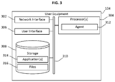
- FIG. 3 is a block diagram of the user equipment 104 according to an embodiment.
- the user equipment 104 which in some cases, may be a mobile computing device or a desktop computer, may include a network interface 302 (e.g., a NIC), one or more processor 304 , user interface 306 (e.g., including a display, speakers, keyboard, mouse, and so forth), and storage 308 (e.g., a volatile and/or non-volatile memory), that are coupled together via bus 310 .
- the storage 308 may store one or more applications 314 and one or more files 316 (e.g., media content files such as audio and/or video files).
- the one or more processors 304 may execute one or more computer readable instructions (e.g., an application 314 ) to implement an agent 312 that may be designed to facilitate the various functionalities performed by the transport manager system 102 a of FIG. 1A and/or transport manager system 102 b of FIG. 1B .
- one or more computer readable instructions e.g., an application 314
- an agent 312 may be designed to facilitate the various functionalities performed by the transport manager system 102 a of FIG. 1A and/or transport manager system 102 b of FIG. 1B .
- Embodiments relate to determining candidate flows for congestion management using a candidate flow detection threshold that is adapted to one or more of one or more characteristics of a data flow, one or more characteristics of a plurality of data flows, a time of day, a type of device, an identity of a device, an identity of an endpoint of a data flow, and the like.
- the plurality of data flows may be data flows throughout all or a portion a data communication network, data flows to or from an individual device, data flows to or from a particular type or model of device, data flows transiting through a node or group of nodes in a network, and so on.
- FIG. 4 illustrates decision-making logic of a process 400 for a video buffer size-based candidate flow detection threshold calculation logic according to an embodiment.
- a candidate flow detector identifies flows that may be videos and adjusts a candidate flow detection threshold based on an amount of buffer (time) that may already have been delivered to a video playback device.
- the process 400 may be performed by a flow manager such as the flow manager 212 a of FIGS. 2A and 2C .
- the process 400 may be performed by a flow manager such as the flow manager 212 b of FIGS. 2B and 2C .
- the process 400 detects, by monitoring data transfer sessions, data flows passing through the data transport network.
- the process 400 determines for each flow whether it may be a video flow.
- the process 400 may detect that a flow may be a video flow through various methods including but not limited to, content destination identification (such as by recognizing an endpoint of a flow as a source of video flows), traffic pattern recognition, DNS sniffing and deep packet inspection.
- the identification of the data transfer session as a video may also be performed by another network node and that information conveyed to process 400 .
- some methods of identifying video flows may incorrectly identify non-video data flows as video data flows, but the incorrectly identified data flows may still be identified as candidate flows and managed accordingly.
- a throughput of the video flow is determined.
- the process 400 determines a video encoding rate (that is, a video bitrate; more generally, a consumption rate for the media being transferred by the flow) that is being delivered.
- the video encoding rate can be determined by observing properties of the data transfer session or inferred from the transfer rate of the data transfer session.
- the process 400 adjusts the candidate flow detection threshold so that the data transfer session will be identified as a candidate flow after a specific amount of video playback has been delivered to a buffer of the device receiving the data of the data transfer session.
- the process 400 may seek to categorize a video flow as a candidate flow when 30 seconds of the video being transmitted using the flow is delivered at the destination of the flow.
- a video flow A may have a throughput of 1.5 Mbps, from which the process 400 may infer that video flow A is delivering 480p video.
- 480p video may be estimated to have an encoding rate of 1.3 Mbps.
- a video flow B may have a throughput of 7 Mbps, from which the process 400 may infer that video flow A is delivering 1080p video.
- 1080p video may be estimated to have an encoding rate of 5 Mbps.
- Managing the candidate flow may include pacing the candidate flow to reduce its throughput.
- pacing a candidate flow may be performed by inserting latencies between, delaying, or buffering packets of the candidate flow, as described in U.S. Patent Application Publication No. 2016/0261510, referenced above.
- pacing a candidate flow may include other using other congestion control mechanisms, such as dropping packets, sending a signal to a transmitting node to cause a size of a TCP congestion window to be adjusted, and the like.
- the candidate detection threshold is time, but it could have also been bytes delivered or a combination of other values that are adjusted based on the estimated buffer capacity according to various embodiments.
- the process 400 evaluates the data transfer session using the candidate flow detection threshold calculated at S 410 , and determines whether the data transfer session is a candidate flow accordingly. If the data transfer session is determined to be a candidate flow, it may be managed as described above to reduce the potential for network congestion.
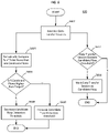
- FIG. 5 illustrates decision-making logic for a process 500 for a video buffer fill rate-based candidate flow detection threshold calculation logic according to an embodiment.
- a candidate flow detector identifies data transfer sessions that are videos or is notified by another network node that a data transfer session is a video and adjusts a candidate flow detection threshold based on a rate of growth of a video playback buffer on the video playback device.
- steps S 502 to S 508 of FIG. 5 correspond to steps S 402 to S 408 of FIG. 4 , and descriptions thereof are therefore omitted in the interest of brevity.
- the process 500 adjusts the candidate flow detection threshold so that the data transfer session will be identified as a candidate flow after a buffer growth rate exceeds a target value.
- a video flow A may have a throughput of 1.5 Mbps, from which the process 400 may infer that video flow A is delivering 480p video.
- 480p video may be estimated to have an encoding rate of 1.3 Mbps.
- a video flow B may have a throughput of 7 Mbps, from which the process 400 may infer that video flow A is delivering 1080p video.
- 1080p video may be estimated to have an encoding rate of 5 Mbps.
- the process 500 compares the estimated buffer growth rate for each video flow to the candidate flow detection threshold to determine whether each video flow is a candidate flow.
- the candidate flow detection threshold is 0.25 Mbps
- video flow A with an estimated buffer growth rate of 0.2 Mbps would not be identified as a candidate flow
- video flow B with an estimated buffer growth rate of 2 Mbps would be identified as a candidate flow.
- a buffer growth rate target value is added to the respective encoding rate to determine the candidate flow detection threshold for each video flow, and the throughput of each video flow is compared to the respective candidate flow detection threshold to determine whether the video flow is a candidate flow.
- the throughput of a video flow exceeds its candidate flow detection threshold, the video flow is determined to be a candidate flow and may subsequently be managed to reduce network congestion.
- FIG. 6 illustrates decision-making logic of a process 600 where a flow detector adjusts the candidate flow detection threshold to achieve a target percentage of candidate flows according to an embodiment.
- a flow detector adjusts a candidate flow detection threshold value to achieve a target percentage of candidate flows across a group of flows.
- the two arrows originating in S 602 indicate potential parallelism: S 604 , S 606 , S 608 , and S 610 comprise a first subprocess of the process 600 , S 612 and S 614 comprise a second subprocess of the process 600 , and the first and second subprocess may be performed in parallel or in sequence, depending on the embodiment.
- the process 600 detects, by monitoring data transfer sessions, data flows passing through one or more nodes of the data transport network.
- the process 600 determines a percentage of active data flows that have been classified as candidate flows. For example, if 1000 data flows are currently being performed on the network, and 31 of those data flows have been determined to be candidate flows, at S 602 the process 600 would determine that 3.1% of the total flows were candidate flows.
- the process 600 compares the percentage of active data flows that are candidate flows to a target percentage. When the percentage of active data flows that are candidate flows is less than the target percentage, the process 600 proceeds to S 608 . When the percentage of active data flows that are candidate flows is greater than the target percentage, the process 600 proceeds to S 610 .
- the process 600 decreases a candidate flow detection threshold in order to increase the number of data flows that are determined to be candidate flows.
- the process 600 increases a candidate flow detection threshold in order to decrease the number of data flows that are determined to be candidate flows.
- the process 600 determines at S 604 that 3.1% of the total data flows are being classified as candidate flows, at S 606 the process 600 proceeds to S 610 , where the process 600 alters the candidate flow detection threshold (for example, by increasing its value) so that a lower percentage of data flows will be determined to be candidate flows.
- the candidate flow detection threshold for example, by increasing its value
- the process 600 proceeds to S 608 , where the process 600 alters the candidate flow detection threshold (for example, by decreasing its value) so that a higher percentage of data flows will be determined to be candidate flows.
- the adjustment of the candidate flow detection threshold may be proportional to a difference between the determined and target percentages. For example, when the target percentage is 3%, the candidate flow detection threshold is 3 MB, and the measured percentage of current flows that are determined to be candidate flows is 2.8%, the candidate flow detection threshold may be adjusted down to 2.8 MB.
- the candidate flow detector could have a target percentage of candidate flows for the entire data transfer network, for a single network node, a destination node, another identifying factor, or a combination thereof.
- a network node may have an elephant flow detection threshold configured according to a target percentage of 3% of all data sessions transported by that network node.
- the process 600 determines for a data transfer session whether the property of the corresponding data flow being used to identify candidate flows exceeds the candidate flow detection threshold. When the candidate flow detection threshold is exceeded, at S 612 the process 600 proceeds to S 614 ; otherwise the process 600 may end.
- the process 600 marks the data transfer session as a candidate flow.
- FIG. 7 illustrates decision-making logic of a process 700 wherein a flow detector adjusts a candidate flow detection threshold value to achieve a target percentile value across a group of flows according to an embodiment.
- the two arrows originating in S 702 indicate potential parallelism:
- S 704 comprises a first subprocess of the process 700
- S 712 and S 714 comprise a second subprocess of the process 700
- the first and second subprocesses may be performed in parallel or in sequence, depend on the embodiment.
- S 702 , S 712 , and S 714 of FIG. 7 respectively correspond to S 602 , S 612 , and S 614 of FIG. 6 , and descriptions of S 702 , S 712 , and S 714 are therefore omitted for brevity.
- the process 700 periodically updates a candidate flow detection threshold according to a distribution of one or more characteristics of data transfer sessions being monitored at S 702 .
- the process 700 sets the candidate flow detection threshold so that flows in a target percentile of the characteristic(s) will be considered candidate flows.
- the property being used to determine candidate flows may be an amount of data transferred.
- the process 700 would determine the distribution of the amount of data transferred. The process 700 would then identify an amount of data transferred that corresponded to a target percentile. For example, if the target percentile was 90%, the process 700 would determine a 90 th percentile amount of data transferred for which 90% of the monitored data transfer sessions had less than that amount of data transferred, and for which 10% of the monitored data transfer sessions had at least that amount of data transferred. The process 700 would then set the candidate detection threshold to the determined 90th percentile amount of data transferred.
- the percentile value could be based on one, several, or a combination of data transfer session characteristics such as amount of data transferred, duration of data transfer, etc. Additionally, the process 700 could be performed across the entire data transport network, for a single network node, for a destination node, for another network node, or for a user device.
- FIG. 8 illustrates decision-making logic of a process 800 according to an embodiment.
- a candidate flow detector uses information either gathered by the candidate flow detector or reported from a separate network node, and uses this to adjust the candidate flow detection threshold for those flows.
- the two arrows originating in S 802 indicate potential parallelism: S 804 and S 806 comprises a first subprocess of the process 800 , S 812 and S 814 comprise a second subprocess of the process 800 , and the first and second subprocesses may be performed in parallel or in sequence, depend on the embodiment.
- S 802 , S 812 , and S 814 of FIG. 8 respectively correspond to S 602 , S 612 , and S 614 of FIG. 6 , and descriptions of S 802 , S 812 , and S 814 are therefore omitted for brevity.
- the process 800 receives information on data flows from another network node, determines information on data flows monitored at S 802 , or both.
- the process 800 adjusts or calculates a candidate flow detection threshold using the information received, calculated, or both at S 804 .
- the candidate flow detection threshold may be adjusted for either all data transfer sessions or for a subset of data transfer sessions.
- the candidate flow detector would be observing data transfer sessions transiting a data transfer network and internally calculating or receiving information from another network node information on the frequency in which a content distribution node or user equipment device is generating or requesting data transport sessions, and on how often those data transfer sessions are being classified as candidate flows.
- the candidate flow detector may track the percentage of data transfer sessions generated by a user device that are identified as candidate flows and trigger a change to the candidate flow detection threshold for subsequent data transfer sessions generated by that user device if the percentage of candidate flow data transfer sessions exceeded a set value.
- the candidate flow detector could determine internally or be notified by another network node of the rate at which candidate flows were being detected for a particular user equipment type (such as a make and/or model of user equipment type) and adjust the candidate flow detection threshold for data transfer sessions for that user equipment type accordingly.
- FIG. 9 illustrates decision-making logic of a process 900 according to an embodiment
- a candidate flow detector adjusts a candidate flows threshold value based on information received from another network node.
- the two arrows originating in S 902 indicate potential parallelism:
- S 904 and S 906 comprises a first subprocess of the process 900
- S 912 and S 914 comprise a second subprocess of the process 900
- the first and second subprocesses may be performed in parallel or in sequence, depend on the embodiment.
- S 902 , S 912 , and S 914 of FIG. 9 respectively correspond to S 602 , S 612 , and S 614 of FIG. 6 , and descriptions of S 902 , S 912 , and S 914 are therefore omitted for brevity.
- the process 900 receives messages from a network node, and may adjust a candidate flow detection threshold for either all data transfer sessions or a subset of data transfer sessions in response to information in the received messages.
- the information in the received messages may be combined with information derived from the monitoring performed at S 902 to adjust the candidate flow detection threshold.
- a data transport network could have a network node that collects data transfer session performance metrics from user equipment or other network nodes and sends that information to the candidate flow detector in order to adjust the candidate flow detection threshold.
- the candidate flow detector could increase the candidate flow detection threshold for those types of data transfer sessions.
- the data transfer quality reporting network node could be any type of equipment or process and collect and send any kind of metrics to the candidate flow detector.
- a continuous duration of a data transfer session (that is, how long a flow has been operating without interruption) may be used to determine whether a flow is a candidate flow.
- FIG. 10 illustrates decision-making logic of a process 1000 wherein a candidate flow detector adjusts a candidate flow detection threshold value based on a time of day according to an embodiment.
- the two arrows originating in S 1002 indicate potential parallelism:
- S 1004 and S 1006 comprises a first subprocess of the process 1000
- S 1012 and S 1014 comprise a second subprocess of the process 1000
- the first and second subprocess may be performed in parallel or in sequence, depend on the embodiment.
- S 1002 , S 1012 , and S 1014 of FIG. 10 respectively correspond to S 602 , S 612 , and S 614 of FIG. 6 , and descriptions of S 1002 , S 1012 , and S 1014 are therefore omitted for brevity.
- the process 1000 may adjust the candidate flow detection threshold value based on the time of the day. For example, on a typical network node, there is little to no traffic at the 1 AM hour and a peak in traffic around 9 PM.
- the candidate flow detector could be configured to adjust the candidate flow detection threshold to a higher value during the middle of the night hours and then lower the candidate flow detection threshold values during peak hours to deal with the different traffic conditions that exist on that network node at different times.
- the time of day may include not only an hour of the day, but also a day of the month or year, a day of the week, whether a day is a holiday, and so on.
- a candidate flow detection threshold may be adjusted according to whether the current time corresponds to a weekend, or whether a current time corresponds to a duration of a scheduled event that is associated with an increase in network traffic (such as a major sporting event).
- FIG. 11 illustrates a computer system 1120 including a processor 1121 , a bus 1122 , a memory 1123 , and a user interface input device 1126 , a user interface output device 1127 , a storage 1128 , and a network interface 1129 that is coupled to a network 1130 .
- the processor 1121 may be a central processing unit (CPU) or a semiconductor device that executes processing instructions stored in the memory 1123 and/or the storage 1128 .
- the memory 1123 and the storage 1128 may include various forms of volatile or non-volatile storage media.
- the memory X23 may include a ROM 1124 and a RAM 125 .
- an embodiment of the present disclosure may be implemented as a computer implemented method or as a non-transitory computer readable medium with computer executable instructions stored thereon.
- the computer readable instructions when executed by the processor, may perform a method according to at least one aspect of the present disclosure.
Landscapes
- Engineering & Computer Science (AREA)
- Computer Networks & Wireless Communication (AREA)
- Signal Processing (AREA)
- Quality & Reliability (AREA)
- Environmental & Geological Engineering (AREA)
- Data Exchanges In Wide-Area Networks (AREA)
- Two-Way Televisions, Distribution Of Moving Picture Or The Like (AREA)
Abstract
Description
Claims (13)
Priority Applications (2)
| Application Number | Priority Date | Filing Date | Title |
|---|---|---|---|
| US16/258,467 US11368398B2 (en) | 2018-01-26 | 2019-01-25 | Systems and methods for identifying candidate flows in data packet networks |
| US17/349,591 US11677665B2 (en) | 2018-01-26 | 2021-06-16 | Systems and methods for identifying candidate flows in data packet networks |
Applications Claiming Priority (2)
| Application Number | Priority Date | Filing Date | Title |
|---|---|---|---|
| US201862622746P | 2018-01-26 | 2018-01-26 | |
| US16/258,467 US11368398B2 (en) | 2018-01-26 | 2019-01-25 | Systems and methods for identifying candidate flows in data packet networks |
Related Child Applications (1)
| Application Number | Title | Priority Date | Filing Date |
|---|---|---|---|
| US17/349,591 Continuation US11677665B2 (en) | 2018-01-26 | 2021-06-16 | Systems and methods for identifying candidate flows in data packet networks |
Publications (2)
| Publication Number | Publication Date |
|---|---|
| US20190238461A1 US20190238461A1 (en) | 2019-08-01 |
| US11368398B2 true US11368398B2 (en) | 2022-06-21 |
Family
ID=67392476
Family Applications (2)
| Application Number | Title | Priority Date | Filing Date |
|---|---|---|---|
| US16/258,467 Active 2039-03-09 US11368398B2 (en) | 2018-01-26 | 2019-01-25 | Systems and methods for identifying candidate flows in data packet networks |
| US17/349,591 Active US11677665B2 (en) | 2018-01-26 | 2021-06-16 | Systems and methods for identifying candidate flows in data packet networks |
Family Applications After (1)
| Application Number | Title | Priority Date | Filing Date |
|---|---|---|---|
| US17/349,591 Active US11677665B2 (en) | 2018-01-26 | 2021-06-16 | Systems and methods for identifying candidate flows in data packet networks |
Country Status (6)
| Country | Link |
|---|---|
| US (2) | US11368398B2 (en) |
| EP (1) | EP3744056A4 (en) |
| JP (1) | JP2021512567A (en) |
| KR (1) | KR20200105539A (en) |
| CN (1) | CN111656740A (en) |
| WO (1) | WO2019148041A1 (en) |
Families Citing this family (13)
| Publication number | Priority date | Publication date | Assignee | Title |
|---|---|---|---|---|
| US9756112B2 (en) | 2015-02-11 | 2017-09-05 | At&T Intellectual Property I, L.P. | Method and system for managing service quality according to network status predictions |
| US11805034B1 (en) | 2016-12-07 | 2023-10-31 | Reservoir Labs, Inc. | Systems and methods for detecting large network flows |
| US10924418B1 (en) * | 2018-02-07 | 2021-02-16 | Reservoir Labs, Inc. | Systems and methods for fast detection of elephant flows in network traffic |
| US10623788B2 (en) | 2018-03-23 | 2020-04-14 | At&T Intellectual Property I, L.P. | Methods to estimate video playback buffer |
| US10693575B2 (en) | 2018-08-31 | 2020-06-23 | At&T Intellectual Property I, L.P. | System and method for throughput prediction for cellular networks |
| US11490149B2 (en) * | 2019-03-15 | 2022-11-01 | At&T Intellectual Property I, L.P. | Cap-based client-network interaction for improved streaming experience |
| CN112367217B (en) * | 2020-10-20 | 2021-12-17 | 武汉大学 | A collaborative mass flow detection method and system for software-defined networks |
| TWI763261B (en) * | 2021-01-19 | 2022-05-01 | 瑞昱半導體股份有限公司 | Data flow classification device |
| CN114827042B (en) * | 2021-01-22 | 2024-06-18 | 瑞昱半导体股份有限公司 | Data flow classification device |
| CN113132180B (en) * | 2021-03-11 | 2022-07-29 | 武汉大学 | Cooperative type large flow detection method facing programmable network |
| US11838209B2 (en) * | 2021-06-01 | 2023-12-05 | Mellanox Technologies, Ltd. | Cardinality-based traffic control |
| CN116192766B (en) * | 2023-02-17 | 2025-02-14 | 支付宝(杭州)信息技术有限公司 | Method and device for adjusting data transmission rate and training congestion control model |
| US12592889B2 (en) * | 2024-05-28 | 2026-03-31 | Mellanox Technologies, Ltd. | Denial of service protection |
Citations (45)
| Publication number | Priority date | Publication date | Assignee | Title |
|---|---|---|---|---|
| US5812069A (en) * | 1995-07-07 | 1998-09-22 | Mannesmann Aktiengesellschaft | Method and system for forecasting traffic flows |
| US20020161914A1 (en) * | 1999-10-29 | 2002-10-31 | Chalmers Technology Licensing Ab | Method and arrangement for congestion control in packet networks |
| US20050052994A1 (en) * | 2003-09-04 | 2005-03-10 | Hewlett-Packard Development Company, L.P. | Method to regulate traffic congestion in a network |
| US20050249497A1 (en) * | 2002-09-13 | 2005-11-10 | Onn Haran | Methods for dynamic bandwidth allocation and queue management in ethernet passive optical networks |
| US20050286416A1 (en) * | 2004-06-25 | 2005-12-29 | Nec Corporation | Communication system |
| US20060233118A1 (en) * | 2005-04-14 | 2006-10-19 | International Business Machines Corporation | Apparatus and method for dynamic packet training |
| US20060256822A1 (en) * | 2005-05-12 | 2006-11-16 | Kwong Sze Ming P | Apparatus for synchronization of digital multimedia data communicated over wired media |
| US20080168220A1 (en) * | 2007-01-08 | 2008-07-10 | International Business Machines Corporation | Using different algorithms to destage different types of data from cache |
| US20080181159A1 (en) * | 2007-01-25 | 2008-07-31 | Metzler Benjamin T | Method and apparatus for reliable multicast communication over wireless network |
| US7543052B1 (en) * | 2003-12-22 | 2009-06-02 | Packeteer, Inc. | Automatic network traffic discovery and classification mechanism including dynamic discovery thresholds |
| US7545748B1 (en) | 2004-09-10 | 2009-06-09 | Packeteer, Inc. | Classification and management of network traffic based on attributes orthogonal to explicit packet attributes |
| US20090182874A1 (en) * | 2004-03-29 | 2009-07-16 | Packeteer, Inc. | Adaptive, Application-Aware Selection of Differentiated Network Services |
| US20090180430A1 (en) * | 2008-01-10 | 2009-07-16 | Fadell Anthony M | Apparatus and methods for network resource allocation |
| US7742406B1 (en) | 2004-12-20 | 2010-06-22 | Packeteer, Inc. | Coordinated environment for classification and control of network traffic |
| US7830813B1 (en) * | 2004-09-30 | 2010-11-09 | Avaya Inc. | Traffic based availability analysis |
| US20110085444A1 (en) * | 2009-10-13 | 2011-04-14 | Brocade Communications Systems, Inc. | Flow autodetermination |
| US20110149737A1 (en) * | 2009-12-23 | 2011-06-23 | Manikam Muthiah | Systems and methods for managing spillover limits in a multi-core system |
| US20120224484A1 (en) * | 2011-03-02 | 2012-09-06 | 3Inova Networks Inc. | Traffic management in distributed wireless networks |
| US20120237129A1 (en) * | 2007-06-18 | 2012-09-20 | Zeitera, Llc | Methods and Apparatus for Providing a Scalable Identification of Digital Video Sequences |
| US20130155865A1 (en) * | 2011-12-14 | 2013-06-20 | Verizon Patent And Licensing Inc. | Label switching or equivalent network multipath traffic control |
| US20130163424A1 (en) * | 2011-12-21 | 2013-06-27 | Cisco Technology, Inc. | System and method for load based optimization in communication networks |
| US20140130906A1 (en) * | 2012-11-14 | 2014-05-15 | Mindray Ds Usa, Inc. | Systems and methods for electronically controlling the flow rates of fluids |
| US20140130905A1 (en) * | 2012-11-14 | 2014-05-15 | Mindray Ds Usa, Inc. | Dual mode electronic flow control system |
| US20140195843A1 (en) * | 2011-12-09 | 2014-07-10 | Beijing Netqin Technology Co., Ltd. | Method and system for battery power saving |
| US20140233421A1 (en) * | 2013-02-19 | 2014-08-21 | Broadcom Corporation | Application Aware Elephant Flow Identification |
| US20140237118A1 (en) | 2013-02-19 | 2014-08-21 | Broadcom Corporation | Application Aware Elephant Flow Management |
| US20140325649A1 (en) * | 2013-04-29 | 2014-10-30 | Telefonaktiebolaget L M Ericsson (Publ) | Method and system to dynamically detect traffic anomalies in a network |
| US20150120856A1 (en) * | 2013-10-29 | 2015-04-30 | Solana Networks Inc. | Method and system for processing network traffic flow data |
| US20150295808A1 (en) * | 2012-10-31 | 2015-10-15 | Matt O'Malley | System and method for dynamically monitoring, analyzing, managing, and alerting packet data traffic and applications |
| US20150339704A1 (en) * | 2012-11-29 | 2015-11-26 | Google Inc. | Valuing online content served to an online publisher |
| US20150372940A1 (en) * | 2014-06-18 | 2015-12-24 | Adobe Systems Incorporated | Data Flow Node Provisioning |
| US20160050150A1 (en) | 2014-08-12 | 2016-02-18 | Arista Networks, Inc. | Method and system for tracking and managing network flows |
| US20160127242A1 (en) * | 2014-10-30 | 2016-05-05 | Henrik Fernand BERNHEIM | System and methods for assigning slots and resolving slot conflicts in an electrical distribution grid |
| EP3028417A1 (en) | 2013-07-31 | 2016-06-08 | International Business Machines Corporation | Data packet processing |
| US20160261510A1 (en) | 2015-03-03 | 2016-09-08 | Opanga Networks, Inc. | Systems and methods for pacing data flows |
| US20160267908A1 (en) * | 2015-03-12 | 2016-09-15 | Sony Corporation | Low-power voice command detector |
| US20170279698A1 (en) * | 2016-03-24 | 2017-09-28 | Cisco Technology, Inc. | Detection and analysis of seasonal network patterns for anomaly detection |
| US20180006948A1 (en) * | 2016-06-30 | 2018-01-04 | Juniper Networks, Inc. | Bandwidth management for resource reservation protocol lsps and non-resource reservation protocol lsps |
| US10003537B2 (en) * | 2015-10-01 | 2018-06-19 | Keysight Technologies Singapore (Holding) Pte Ltd | Egress port overload protection for network packet forwarding systems |
| US20180241677A1 (en) * | 2016-06-28 | 2018-08-23 | Mellanox Technologies Tlv Ltd. | Adaptive flow prioritization |
| US20180310159A1 (en) * | 2017-04-24 | 2018-10-25 | Rapidsos, Inc. | Modular emergency communication flow management system |
| US20190028382A1 (en) * | 2017-07-20 | 2019-01-24 | Vmware Inc. | Methods and apparatus to optimize packet flow among virtualized servers |
| US20190068443A1 (en) * | 2017-08-23 | 2019-02-28 | Futurewei Technologies, Inc. | Automatically optimize parameters via machine learning |
| US20190138934A1 (en) * | 2018-09-07 | 2019-05-09 | Saurav Prakash | Technologies for distributing gradient descent computation in a heterogeneous multi-access edge computing (mec) networks |
| US20190199644A1 (en) * | 2016-06-10 | 2019-06-27 | Telefonaktiebolaget Lm Ericsson (Publ) | Scheduling of Data Flow Transmission in a Data Center |
Family Cites Families (22)
| Publication number | Priority date | Publication date | Assignee | Title |
|---|---|---|---|---|
| US7453801B2 (en) * | 2001-11-08 | 2008-11-18 | Qualcomm Incorporated | Admission control and resource allocation in a communication system supporting application flows having quality of service requirements |
| US20040158626A1 (en) * | 2003-02-11 | 2004-08-12 | Douglas Christopher Paul | Method and apparatus for monitoring data flow to a router |
| JP2007336430A (en) * | 2006-06-19 | 2007-12-27 | Alaxala Networks Corp | Relay device for packets transmitted by connectionless communication and flow control information setting method in this relay device |
| US7881725B2 (en) * | 2006-06-30 | 2011-02-01 | Nokia Corporation | Method and apparatus for providing adaptive thresholding for adjustment to loading conditions |
| BRPI0813927B1 (en) * | 2007-07-09 | 2020-10-20 | Telefonaktiebolaget Lm Ericsson (Publ) | method for controlling a session bit rate, receiver for receiving packet-switched encrypted media, sender for transmitting packet-switched encrypted media and packet-switched communications system |
| JP5064434B2 (en) * | 2009-03-27 | 2012-10-31 | 西日本電信電話株式会社 | Communication control device and communication control method |
| US9124515B2 (en) * | 2010-11-22 | 2015-09-01 | Hewlett-Packard Development Company, L.P. | Elephant flow detection in a computing device |
| US20120330615A1 (en) * | 2011-06-24 | 2012-12-27 | Itron Inc. | Forensic analysis of resource consumption data |
| US8630177B2 (en) * | 2012-02-27 | 2014-01-14 | Cisco Technology, Inc. | Dynamic directed acyclic graph (DAG) root bypass for computer networks |
| CN102724108B (en) * | 2012-05-22 | 2015-02-04 | 库柏资讯软体股份有限公司 | Network packet and database packet audit system and its correlation audit device |
| EP2704378B1 (en) * | 2012-08-27 | 2016-07-20 | Itron, Inc. | Bandwidth Management in an Advanced Metering Infrastructure |
| US9571403B2 (en) * | 2013-02-07 | 2017-02-14 | Broadcom Corporation | Packet marking for flow management, including deadline aware flow management |
| JP2014232923A (en) * | 2013-05-28 | 2014-12-11 | 日本電気株式会社 | Communication equipment, cyber attack detection method and program |
| US9967199B2 (en) * | 2013-12-09 | 2018-05-08 | Nicira, Inc. | Inspecting operations of a machine to detect elephant flows |
| WO2015138993A1 (en) * | 2014-03-14 | 2015-09-17 | Huawei Technologies Co., Ltd. | System and method for dynamic effective rate estimation for real-time video traffic |
| US9451095B2 (en) * | 2014-06-17 | 2016-09-20 | Alcatel Lucent | Charging in a software defined network |
| US10355957B2 (en) * | 2014-07-22 | 2019-07-16 | Redknee Inc. | Method, system and apparatus for monitoring error correction data in media sessions |
| JP2016152453A (en) * | 2015-02-16 | 2016-08-22 | 株式会社日立製作所 | Communication control system, communication method, and gateway device |
| US10573170B2 (en) * | 2016-01-25 | 2020-02-25 | Mandar Anant Joshi | Consumption based media playback |
| JP6425273B2 (en) * | 2016-03-31 | 2018-11-21 | Necプラットフォームズ株式会社 | Communication relay device, communication control program and communication control method |
| CN107342906B (en) * | 2016-04-29 | 2020-04-21 | 华为技术有限公司 | A kind of elephant flow detection method, equipment and system |
| US20180351868A1 (en) * | 2017-05-31 | 2018-12-06 | Cisco Technology, Inc. | Multicast abr flow prioritization using error detection thresholds in the receiver |
-
2019
- 2019-01-25 JP JP2020561614A patent/JP2021512567A/en active Pending
- 2019-01-25 KR KR1020207024696A patent/KR20200105539A/en not_active Ceased
- 2019-01-25 CN CN201980010404.XA patent/CN111656740A/en active Pending
- 2019-01-25 EP EP19743274.3A patent/EP3744056A4/en active Pending
- 2019-01-25 WO PCT/US2019/015294 patent/WO2019148041A1/en not_active Ceased
- 2019-01-25 US US16/258,467 patent/US11368398B2/en active Active
-
2021
- 2021-06-16 US US17/349,591 patent/US11677665B2/en active Active
Patent Citations (45)
| Publication number | Priority date | Publication date | Assignee | Title |
|---|---|---|---|---|
| US5812069A (en) * | 1995-07-07 | 1998-09-22 | Mannesmann Aktiengesellschaft | Method and system for forecasting traffic flows |
| US20020161914A1 (en) * | 1999-10-29 | 2002-10-31 | Chalmers Technology Licensing Ab | Method and arrangement for congestion control in packet networks |
| US20050249497A1 (en) * | 2002-09-13 | 2005-11-10 | Onn Haran | Methods for dynamic bandwidth allocation and queue management in ethernet passive optical networks |
| US20050052994A1 (en) * | 2003-09-04 | 2005-03-10 | Hewlett-Packard Development Company, L.P. | Method to regulate traffic congestion in a network |
| US7543052B1 (en) * | 2003-12-22 | 2009-06-02 | Packeteer, Inc. | Automatic network traffic discovery and classification mechanism including dynamic discovery thresholds |
| US20090182874A1 (en) * | 2004-03-29 | 2009-07-16 | Packeteer, Inc. | Adaptive, Application-Aware Selection of Differentiated Network Services |
| US20050286416A1 (en) * | 2004-06-25 | 2005-12-29 | Nec Corporation | Communication system |
| US7545748B1 (en) | 2004-09-10 | 2009-06-09 | Packeteer, Inc. | Classification and management of network traffic based on attributes orthogonal to explicit packet attributes |
| US7830813B1 (en) * | 2004-09-30 | 2010-11-09 | Avaya Inc. | Traffic based availability analysis |
| US7742406B1 (en) | 2004-12-20 | 2010-06-22 | Packeteer, Inc. | Coordinated environment for classification and control of network traffic |
| US20060233118A1 (en) * | 2005-04-14 | 2006-10-19 | International Business Machines Corporation | Apparatus and method for dynamic packet training |
| US20060256822A1 (en) * | 2005-05-12 | 2006-11-16 | Kwong Sze Ming P | Apparatus for synchronization of digital multimedia data communicated over wired media |
| US20080168220A1 (en) * | 2007-01-08 | 2008-07-10 | International Business Machines Corporation | Using different algorithms to destage different types of data from cache |
| US20080181159A1 (en) * | 2007-01-25 | 2008-07-31 | Metzler Benjamin T | Method and apparatus for reliable multicast communication over wireless network |
| US20120237129A1 (en) * | 2007-06-18 | 2012-09-20 | Zeitera, Llc | Methods and Apparatus for Providing a Scalable Identification of Digital Video Sequences |
| US20090180430A1 (en) * | 2008-01-10 | 2009-07-16 | Fadell Anthony M | Apparatus and methods for network resource allocation |
| US20110085444A1 (en) * | 2009-10-13 | 2011-04-14 | Brocade Communications Systems, Inc. | Flow autodetermination |
| US20110149737A1 (en) * | 2009-12-23 | 2011-06-23 | Manikam Muthiah | Systems and methods for managing spillover limits in a multi-core system |
| US20120224484A1 (en) * | 2011-03-02 | 2012-09-06 | 3Inova Networks Inc. | Traffic management in distributed wireless networks |
| US20140195843A1 (en) * | 2011-12-09 | 2014-07-10 | Beijing Netqin Technology Co., Ltd. | Method and system for battery power saving |
| US20130155865A1 (en) * | 2011-12-14 | 2013-06-20 | Verizon Patent And Licensing Inc. | Label switching or equivalent network multipath traffic control |
| US20130163424A1 (en) * | 2011-12-21 | 2013-06-27 | Cisco Technology, Inc. | System and method for load based optimization in communication networks |
| US20150295808A1 (en) * | 2012-10-31 | 2015-10-15 | Matt O'Malley | System and method for dynamically monitoring, analyzing, managing, and alerting packet data traffic and applications |
| US20140130905A1 (en) * | 2012-11-14 | 2014-05-15 | Mindray Ds Usa, Inc. | Dual mode electronic flow control system |
| US20140130906A1 (en) * | 2012-11-14 | 2014-05-15 | Mindray Ds Usa, Inc. | Systems and methods for electronically controlling the flow rates of fluids |
| US20150339704A1 (en) * | 2012-11-29 | 2015-11-26 | Google Inc. | Valuing online content served to an online publisher |
| US20140233421A1 (en) * | 2013-02-19 | 2014-08-21 | Broadcom Corporation | Application Aware Elephant Flow Identification |
| US20140237118A1 (en) | 2013-02-19 | 2014-08-21 | Broadcom Corporation | Application Aware Elephant Flow Management |
| US20140325649A1 (en) * | 2013-04-29 | 2014-10-30 | Telefonaktiebolaget L M Ericsson (Publ) | Method and system to dynamically detect traffic anomalies in a network |
| EP3028417A1 (en) | 2013-07-31 | 2016-06-08 | International Business Machines Corporation | Data packet processing |
| US20150120856A1 (en) * | 2013-10-29 | 2015-04-30 | Solana Networks Inc. | Method and system for processing network traffic flow data |
| US20150372940A1 (en) * | 2014-06-18 | 2015-12-24 | Adobe Systems Incorporated | Data Flow Node Provisioning |
| US20160050150A1 (en) | 2014-08-12 | 2016-02-18 | Arista Networks, Inc. | Method and system for tracking and managing network flows |
| US20160127242A1 (en) * | 2014-10-30 | 2016-05-05 | Henrik Fernand BERNHEIM | System and methods for assigning slots and resolving slot conflicts in an electrical distribution grid |
| US20160261510A1 (en) | 2015-03-03 | 2016-09-08 | Opanga Networks, Inc. | Systems and methods for pacing data flows |
| US20160267908A1 (en) * | 2015-03-12 | 2016-09-15 | Sony Corporation | Low-power voice command detector |
| US10003537B2 (en) * | 2015-10-01 | 2018-06-19 | Keysight Technologies Singapore (Holding) Pte Ltd | Egress port overload protection for network packet forwarding systems |
| US20170279698A1 (en) * | 2016-03-24 | 2017-09-28 | Cisco Technology, Inc. | Detection and analysis of seasonal network patterns for anomaly detection |
| US20190199644A1 (en) * | 2016-06-10 | 2019-06-27 | Telefonaktiebolaget Lm Ericsson (Publ) | Scheduling of Data Flow Transmission in a Data Center |
| US20180241677A1 (en) * | 2016-06-28 | 2018-08-23 | Mellanox Technologies Tlv Ltd. | Adaptive flow prioritization |
| US20180006948A1 (en) * | 2016-06-30 | 2018-01-04 | Juniper Networks, Inc. | Bandwidth management for resource reservation protocol lsps and non-resource reservation protocol lsps |
| US20180310159A1 (en) * | 2017-04-24 | 2018-10-25 | Rapidsos, Inc. | Modular emergency communication flow management system |
| US20190028382A1 (en) * | 2017-07-20 | 2019-01-24 | Vmware Inc. | Methods and apparatus to optimize packet flow among virtualized servers |
| US20190068443A1 (en) * | 2017-08-23 | 2019-02-28 | Futurewei Technologies, Inc. | Automatically optimize parameters via machine learning |
| US20190138934A1 (en) * | 2018-09-07 | 2019-05-09 | Saurav Prakash | Technologies for distributing gradient descent computation in a heterogeneous multi-access edge computing (mec) networks |
Non-Patent Citations (2)
| Title |
|---|
| Extended European Search Report for EP Application No. 19743274.3, dated Sep. 20, 2021. |
| International Search Report dated May 1, 2019 for PCT Application PCT/US2019/015294. |
Also Published As
| Publication number | Publication date |
|---|---|
| US20210314261A1 (en) | 2021-10-07 |
| EP3744056A4 (en) | 2021-10-20 |
| WO2019148041A1 (en) | 2019-08-01 |
| JP2021512567A (en) | 2021-05-13 |
| US11677665B2 (en) | 2023-06-13 |
| EP3744056A1 (en) | 2020-12-02 |
| US20190238461A1 (en) | 2019-08-01 |
| KR20200105539A (en) | 2020-09-07 |
| CN111656740A (en) | 2020-09-11 |
Similar Documents
| Publication | Publication Date | Title |
|---|---|---|
| US11677665B2 (en) | Systems and methods for identifying candidate flows in data packet networks | |
| US12081446B2 (en) | Systems and methods for pacing data flows | |
| US9866492B2 (en) | Localized congestion exposure | |
| US9948561B2 (en) | Setting delay precedence on queues before a bottleneck link based on flow characteristics | |
| US9113356B2 (en) | Control of data flows over transport networks | |
| CN114079638B (en) | Data transmission method, device and storage medium for multi-protocol hybrid network | |
| US20190149475A1 (en) | Unified streamlining for data traffic | |
| US20180212845A1 (en) | Network resource handling | |
| US10523571B2 (en) | Processing data items in a communications network | |
| US8989008B2 (en) | Wirespeed TCP packet window field modification for networks having radio segments | |
| Nossenson et al. | Active queue management in blind access networks | |
| Raza et al. | CHOKe-FS: CHOKe with fair bandwidth share | |
| Sharma et al. | IPv4 Vs IPv6 QoS: A challenge in MANET | |
| EP3185493A1 (en) | Data packet transport layer with utility based fairness |
Legal Events
| Date | Code | Title | Description |
|---|---|---|---|
| FEPP | Fee payment procedure |
Free format text: ENTITY STATUS SET TO UNDISCOUNTED (ORIGINAL EVENT CODE: BIG.); ENTITY STATUS OF PATENT OWNER: SMALL ENTITY |
|
| FEPP | Fee payment procedure |
Free format text: ENTITY STATUS SET TO SMALL (ORIGINAL EVENT CODE: SMAL); ENTITY STATUS OF PATENT OWNER: SMALL ENTITY |
|
| AS | Assignment |
Owner name: OPANGA NETWORKS, INC., WASHINGTON Free format text: ASSIGNMENT OF ASSIGNORS INTEREST;ASSIGNORS:MILLER, MICHELLE;BURNETTE, JOHN M.;HADORN, BEN;AND OTHERS;REEL/FRAME:049581/0684 Effective date: 20190614 |
|
| STPP | Information on status: patent application and granting procedure in general |
Free format text: NON FINAL ACTION COUNTED, NOT YET MAILED |
|
| STPP | Information on status: patent application and granting procedure in general |
Free format text: FINAL REJECTION MAILED |
|
| STPP | Information on status: patent application and granting procedure in general |
Free format text: ADVISORY ACTION MAILED |
|
| STPP | Information on status: patent application and granting procedure in general |
Free format text: NON FINAL ACTION MAILED |
|
| STPP | Information on status: patent application and granting procedure in general |
Free format text: NON FINAL ACTION MAILED |
|
| STPP | Information on status: patent application and granting procedure in general |
Free format text: RESPONSE TO NON-FINAL OFFICE ACTION ENTERED AND FORWARDED TO EXAMINER |
|
| STPP | Information on status: patent application and granting procedure in general |
Free format text: FINAL REJECTION MAILED |
|
| STCV | Information on status: appeal procedure |
Free format text: NOTICE OF APPEAL FILED |
|
| STPP | Information on status: patent application and granting procedure in general |
Free format text: NOTICE OF ALLOWANCE MAILED -- APPLICATION RECEIVED IN OFFICE OF PUBLICATIONS |
|
| STPP | Information on status: patent application and granting procedure in general |
Free format text: PUBLICATIONS -- ISSUE FEE PAYMENT RECEIVED |
|
| STPP | Information on status: patent application and granting procedure in general |
Free format text: PUBLICATIONS -- ISSUE FEE PAYMENT VERIFIED |
|
| STCF | Information on status: patent grant |
Free format text: PATENTED CASE |
|
| MAFP | Maintenance fee payment |
Free format text: PAYMENT OF MAINTENANCE FEE, 4TH YR, SMALL ENTITY (ORIGINAL EVENT CODE: M2551); ENTITY STATUS OF PATENT OWNER: SMALL ENTITY Year of fee payment: 4 |