US11368348B2 - Signal transmission method and apparatus - Google Patents
Signal transmission method and apparatus Download PDFInfo
- Publication number
- US11368348B2 US11368348B2 US17/324,873 US202117324873A US11368348B2 US 11368348 B2 US11368348 B2 US 11368348B2 US 202117324873 A US202117324873 A US 202117324873A US 11368348 B2 US11368348 B2 US 11368348B2
- Authority
- US
- United States
- Prior art keywords
- data
- filter
- pieces
- frequency domain
- time domain
- Prior art date
- Legal status (The legal status is an assumption and is not a legal conclusion. Google has not performed a legal analysis and makes no representation as to the accuracy of the status listed.)
- Active
Links
Images


Classifications
-
- H—ELECTRICITY
- H04—ELECTRIC COMMUNICATION TECHNIQUE
- H04L—TRANSMISSION OF DIGITAL INFORMATION, e.g. TELEGRAPHIC COMMUNICATION
- H04L27/00—Modulated-carrier systems
- H04L27/26—Systems using multi-frequency codes
- H04L27/2601—Multicarrier modulation systems
- H04L27/2614—Peak power aspects
- H04L27/2621—Reduction thereof using phase offsets between subcarriers
-
- H—ELECTRICITY
- H04—ELECTRIC COMMUNICATION TECHNIQUE
- H04L—TRANSMISSION OF DIGITAL INFORMATION, e.g. TELEGRAPHIC COMMUNICATION
- H04L27/00—Modulated-carrier systems
- H04L27/26—Systems using multi-frequency codes
- H04L27/2601—Multicarrier modulation systems
- H04L27/2626—Arrangements specific to the transmitter only
- H04L27/2627—Modulators
-
- H—ELECTRICITY
- H04—ELECTRIC COMMUNICATION TECHNIQUE
- H04L—TRANSMISSION OF DIGITAL INFORMATION, e.g. TELEGRAPHIC COMMUNICATION
- H04L27/00—Modulated-carrier systems
- H04L27/18—Phase-modulated carrier systems, i.e. using phase-shift keying
- H04L27/20—Modulator circuits; Transmitter circuits
-
- H—ELECTRICITY
- H04—ELECTRIC COMMUNICATION TECHNIQUE
- H04L—TRANSMISSION OF DIGITAL INFORMATION, e.g. TELEGRAPHIC COMMUNICATION
- H04L27/00—Modulated-carrier systems
- H04L27/26—Systems using multi-frequency codes
- H04L27/2601—Multicarrier modulation systems
- H04L27/2626—Arrangements specific to the transmitter only
- H04L27/2627—Modulators
- H04L27/2628—Inverse Fourier transform modulators, e.g. inverse fast Fourier transform [IFFT] or inverse discrete Fourier transform [IDFT] modulators
-
- H—ELECTRICITY
- H04—ELECTRIC COMMUNICATION TECHNIQUE
- H04L—TRANSMISSION OF DIGITAL INFORMATION, e.g. TELEGRAPHIC COMMUNICATION
- H04L27/00—Modulated-carrier systems
- H04L27/26—Systems using multi-frequency codes
- H04L27/2601—Multicarrier modulation systems
- H04L27/2626—Arrangements specific to the transmitter only
- H04L27/2627—Modulators
- H04L27/2634—Inverse fast Fourier transform [IFFT] or inverse discrete Fourier transform [IDFT] modulators in combination with other circuits for modulation
- H04L27/2636—Inverse fast Fourier transform [IFFT] or inverse discrete Fourier transform [IDFT] modulators in combination with other circuits for modulation with FFT or DFT modulators, e.g. standard single-carrier frequency-division multiple access [SC-FDMA] transmitter or DFT spread orthogonal frequency division multiplexing [DFT-SOFDM]
Definitions
- This application relates to the field of communications technologies, and in particular, to a signal transmission method and apparatus.
- a transmit end performs power amplification on a signal by using a power amplifier (PA) before sending the signal.
- a function of amplifying a signal by the PA includes a linear region and a non-linear region. As shown in FIG. 1 , when a power of an input signal is comparatively low, the input signal corresponds to the linear region of the PA; or when a power of an input signal is comparatively high, the input signal corresponds to the non-linear region of the PA.
- an amplification gain of the PA is a constant, that is, a power ratio of the pre-amplification input signal to an amplified output signal is a constant, and phases of the input signal and the output signal are the same.
- an amplification gain of the PA decreases with an increase in the power of the input signal, and the PA may even have no amplification effect.
- a sampling point with a comparatively small amplitude corresponds to the linear region of the PA, and a sampling point with a comparatively large amplitude corresponds to the non-linear region of the PA.
- amplification gains in the linear region and the non-linear region of the PA are different, amplification gains for sampling points of the input signal that have different amplitudes are different after the input signal passes through the PA, thereby causing a waveform distortion of the output signal.
- a waveform distortion degree of the output signal is directly proportional to a peak to average power ratio (PAPR) of the input signal. To be specific, a higher PAPR of the input signal indicates a more serious waveform distortion after the input signal passes through the PA.
- PAPR peak to average power ratio
- This application provides a signal transmission method and apparatus, to resolve a problem that because a PAPR of a signal is comparatively high, a waveform distortion of the signal is comparatively serious after power amplification is performed on the signal by using a PA.
- this application provides a signal transmission method.
- the method may be applied to a transmit end, a chip, a chipset, a functional module that is in a chip and that performs the method, another module that can be used to implement the method, or the like.
- the method includes: separately performing phase rotation on M pieces of modulated data to obtain M pieces of phase-rotated data, where a phase factor used for performing phase rotation on the M pieces of modulated data is determined based on M.
- the method further includes: determining time domain data based on the M pieces of phase-rotated data, and sending the time domain data to a receive end.
- a phase of the modulated data is adjusted based on the phase factor corresponding to a length of the modulated data, so that a PAPR of time domain data corresponding to the modulated data can be lower, thereby reducing a waveform distortion degree of the time domain data after the time domain data passes through a PA, increasing a power of an output signal obtained after the time domain data passes through the PA, and improving demodulation performance of a receive end.
- phase rotation when phase rotation is separately performed on the M pieces of modulated data, phase rotation may be performed on modulated data with an index m in the M pieces of modulated data based on a phase factor corresponding to the modulated data with the index m, where m traverses 0 to M ⁇ 1, and m is an integer.
- a phase factor is determined based on a length M of modulated data, so that modulated data with different lengths can have corresponding phase factors, and a PAPR of time domain data corresponding to the modulated data can be lower, thereby reducing a waveform distortion degree of the time domain data after the time domain data passes through a PA, increasing a power of an output signal obtained after the time domain data passes through the PA, and improving demodulation performance of a receive end.
- a PAPR of modulated data with any length can be reduced.
- A may be equal to 1, ⁇ 1, 3, or ⁇ 3, and h may be equal to 4.
- Fourier transform and inverse Fourier transform may be sequentially performed on the M pieces of phase-rotated data to obtain the time domain data.
- Fourier transform, frequency domain filtering, and inverse Fourier transform may be sequentially performed on the M pieces of phase-rotated data to obtain the time domain data.
- a frequency domain filter for the frequency domain filtering may be determined based on an initial filter including KxM filter coefficients, and the frequency domain filter includes M filter coefficients.
- an extraction operation is performed on the initial filter to obtain the frequency domain filter.
- the generated frequency domain filter is orthogonal.
- the M filter coefficients may be extracted from the KxM filter coefficients in the initial filter at a step of K to obtain the frequency domain filter.
- the frequency domain filter obtained in the foregoing embodiment comparatively small interference may be caused when frequency domain filtering is performed. Therefore, during ideal channel estimation with a known noise, a network device can correctly demodulate the modulated data.
- S filter (m) indicates the filter coefficient with the index m in the frequency domain filter coefficients
- S base ((A ⁇ K ⁇ M/h)mod K+m ⁇ K) indicates a filter coefficient with an index (A ⁇ K ⁇ M/h)mod K+m ⁇ K in the initial filter
- a and h are integers.
- K may be determined based on M.
- K is determined based on the length M of the modulated data, so that the frequency domain filter obtained through extraction by using K has comparatively good orthogonality, thereby reducing interference caused when the frequency domain filter performs frequency domain filtering.
- a frequency domain filter coefficient for the frequency domain filtering may be alternatively determined based on signaling from a network device.
- Fourier transform, inverse Fourier transform, and time domain filtering may be sequentially performed on the M pieces of phase-rotated data to obtain the time domain data.
- a time domain filter coefficient for the time domain filtering may be determined based on signaling from a network device.
- a time domain filter for the time domain filtering may be obtained by performing inverse Fourier transform on the frequency domain filter.
- an extraction operation is performed on the initial filter to obtain the frequency domain filter.
- inverse Fourier transform is performed on the frequency domain filter to obtain the time domain filter.
- the time domain filter can reduce interference caused during time domain filtering. Therefore, during ideal channel estimation with a known noise, a network device can correctly demodulate the modulated data.
- the M pieces of modulated data are BPSK modulated data.
- this application provides a signal transmission method.
- the method may be applied to a transmit end, a chip, a chipset, a functional module that is in a chip and that performs the method, another module that can be used to implement the method, or the like.
- the method includes: performing Fourier transform on M pieces of modulated data to obtain M pieces of frequency domain data, and performing a cyclic shift on the M pieces of frequency domain data to obtain M pieces of shifted frequency domain data, where a shift length used for performing the cyclic shift on the frequency domain data is determined based on M.
- the method further includes: determining time domain data based on the M pieces of shifted frequency domain data, and sending the time domain data to a receive end.
- the cyclic shift is performed on the frequency domain data based on the shift length corresponding to a length of the frequency domain data, so that an effect of adjusting a phase of the modulated data based on a phase factor corresponding to a length of the modulated data can be implemented, and a PAPR of time domain data corresponding to the modulated data can be lower, thereby reducing a waveform distortion degree of the time domain data after the time domain data passes through a PA, increasing a power of an output signal obtained after the time domain data passes through the PA, and improving demodulation performance of a receive end.
- d shift (k) is the shifted frequency domain data with the index k in the M pieces of shifted frequency domain data
- d fre ((k ⁇ Q shift )mod M) is frequency domain data with an index (k ⁇ Q shift ) mod M in the M pieces of frequency domain data
- Q shift is the shift length.
- Q shift ⁇ M ⁇ A/h ⁇ , where A and h are integers.
- a cyclic shift is performed on frequency domain data d fre with a length of M to obtain shifted frequency domain data d shift with a length of M.
- a shift length of the cyclic shift is determined by the length M.
- modulated data with different lengths has corresponding shift lengths, so that a PAPR of time domain data corresponding to the modulated data can be lower, thereby reducing a waveform distortion degree of the time domain data after the time domain data passes through a PA, increasing a power of an output signal obtained after the time domain data passes through the PA, and improving demodulation performance of a receive end.
- a PAPR of modulated data with any length can be reduced.
- A may be equal to 1, ⁇ 1, 3, or ⁇ 3, and h may be equal to 4.
- inverse Fourier transform may be performed on the M pieces of shifted frequency domain data to obtain the time domain data.
- frequency domain filtering and inverse Fourier transform may be sequentially performed on the M pieces of shifted frequency domain data to obtain the time domain data.
- a frequency domain filter for the frequency domain filtering is determined based on an initial filter including KxM filter coefficients, and the frequency domain filter includes M filter coefficients.
- an extraction operation is performed on the initial filter to obtain the frequency domain filter.
- the generated frequency domain filter is orthogonal.
- the M filter coefficients may be extracted from the KxM filter coefficients in the initial filter at a step of K to obtain the frequency domain filter.
- the frequency domain filter obtained in the foregoing embodiment comparatively small interference may be caused when frequency domain filtering is performed. Therefore, during ideal channel estimation with a known noise, a network device can correctly demodulate the modulated data.
- S filter (m) indicates the filter coefficient with the index m in the frequency domain filter coefficients
- S base ((A ⁇ K ⁇ M/h)mod K+m ⁇ K) indicates a filter coefficient with an index (A ⁇ K ⁇ M/h)mod K+m ⁇ K in the initial filter
- a and h are integers.
- K may be determined based on M.
- K is determined based on the length M of the modulated data, so that the frequency domain filter obtained through extraction by using K has comparatively good orthogonality, thereby reducing interference caused when the frequency domain filter performs frequency domain filtering.
- a frequency domain filter coefficient for the frequency domain filtering may be alternatively determined based on signaling from a network device.
- inverse Fourier transform and time domain filtering may be sequentially performed on the M pieces of shifted frequency domain data to obtain the time domain data.
- a time domain filter coefficient for the time domain filtering may be determined based on signaling from a network device.
- a time domain filter for the time domain filtering may be obtained by performing inverse Fourier transform on the frequency domain filter.
- an extraction operation is performed on the initial filter to obtain the frequency domain filter.
- inverse Fourier transform is performed on the frequency domain filter to obtain the time domain filter.
- the time domain filter can reduce interference caused during time domain filtering. Therefore, during ideal channel estimation with a known noise, a network device can correctly demodulate the modulated data.
- the M pieces of modulated data are BPSK modulated data.
- an embodiment of this application provides an apparatus.
- the apparatus may be a transmit end, or may be an apparatus in a transmit end, or may be another apparatus that can implement corresponding functions performed by the transmit end in any design example of the first aspect.
- the apparatus may include a phase rotation module, a determining module, and a sending module. These modules may perform corresponding functions performed by the transmit end in any design example of the first aspect. Details are as follows.
- the phase rotation module is configured to separately perform phase rotation on M pieces of modulated data to obtain M pieces of phase-rotated data, where a phase factor used for performing phase rotation on the M pieces of modulated data is determined based on M.
- the determining module is configured to determine time domain data based on the M pieces of phase-rotated data.
- the sending module is configured to send the time domain data to a receive end.
- the phase rotation module may be specifically configured to perform phase rotation on modulated data with an index m in the M pieces of modulated data based on a phase factor corresponding to the modulated data with the index m, where m traverses 0 to M ⁇ 1, and m is an integer.
- e j ⁇ m is the phase factor corresponding to the modulated data with the index m, and A and h are integers.
- the determining module may be specifically configured to sequentially perform Fourier transform, frequency domain filtering, and inverse Fourier transform on the M pieces of phase-rotated data to obtain the time domain data.
- a frequency domain filter for the frequency domain filtering is determined based on an initial filter including K ⁇ M filter coefficients, and the frequency domain filter includes M filter coefficients.
- the determining module may be further configured to determine the frequency domain filter based on the initial filter including the KxM filter coefficients.
- the determining module when determining the frequency domain filter for the frequency domain filtering based on the initial filter including the K ⁇ M filter coefficients, the determining module may be specifically configured to extract the M filter coefficients from the KxM filter coefficients in the initial filter at a step of K to obtain the frequency domain filter.
- S filter (m) indicates the filter coefficient with the index m in the frequency domain filter coefficients
- S base ((A ⁇ K ⁇ M/h)mod K+m ⁇ K) indicates a filter coefficient with an index (A ⁇ K ⁇ M/h)mod K+m ⁇ K in the initial filter
- a and h are integers.
- K may be determined based on M.
- the determining module when determining the time domain data based on the M pieces of phase-rotated data, may be further specifically configured to sequentially perform Fourier transform, inverse Fourier transform, and time domain filtering on the M pieces of phase-rotated data to obtain the time domain data.
- a time domain filter coefficient for the time domain filtering is determined based on signaling from a network device.
- the M pieces of modulated data may be BPSK modulated data.
- an embodiment of this application provides an apparatus.
- the apparatus may be a transmit end, or may be an apparatus in a transmit end, or may be another apparatus that can implement corresponding functions performed by the transmit end in any design example of the second aspect.
- the apparatus may include a Fourier transform module, a cyclic shift module, a determining module, and a sending module. These modules may perform corresponding functions performed by the transmit end in any design example of the second aspect. Details are as follows.
- the Fourier transform module is configured to perform Fourier transform on M pieces of modulated data to obtain M pieces of frequency domain data.
- the cyclic shift module is configured to perform a cyclic shift on the M pieces of frequency domain data to obtain M pieces of shifted frequency domain data, where a shift length for performing the cyclic shift on the frequency domain data is determined based on M.
- the determining module is configured to determine time domain data based on the M pieces of shifted frequency domain data.
- the sending module is configured to send the time domain data to a receive end.
- d shift (k) is the shifted frequency domain data with the index k in the M pieces of shifted frequency domain data
- d fre ((k ⁇ Q shift )mod M) is frequency domain data with an index (k ⁇ Q shift )mod M in the M pieces of frequency domain data
- Q shift is the shift length
- a and h are integers.
- the determining module may be specifically configured to sequentially perform frequency domain filtering and inverse Fourier transform on the M pieces of shifted frequency domain data to obtain the time domain data.
- a frequency domain filter for the frequency domain filtering is determined based on an initial filter including KxM filter coefficients, and the frequency domain filter includes M filter coefficients.
- the determining module may be further configured to determine the frequency domain filter based on the initial filter including the K ⁇ M filter coefficients.
- the determining module when determining the frequency domain filter for the frequency domain filtering based on the initial filter including the K ⁇ M filter coefficients, the determining module may be specifically configured to extract the M filter coefficients from the K ⁇ M filter coefficients in the initial filter at a step of K to obtain the frequency domain filter.
- S filter (m) indicates the filter coefficient with the index m in the frequency domain filter coefficients
- S base ((A ⁇ K ⁇ M/h)mod K+m ⁇ K) indicates a filter coefficient with an index (A ⁇ K ⁇ M/h)mod K+m ⁇ K in the initial filter
- a and h are integers.
- K may be determined based on M.
- the determining module when determining the time domain data based on the M pieces of shifted frequency domain data, may be further specifically configured to sequentially perform inverse Fourier transform and time domain filtering on the M pieces of shifted frequency domain data to obtain the time domain data.
- a time domain filter coefficient for the time domain filtering is determined based on signaling from a network device.
- the M pieces of modulated data may be BPSK modulated data.
- an embodiment of this application further provides an apparatus.
- the apparatus includes a processor, configured to implement functions of the transmit end in the method described in the first aspect or the second aspect.
- the apparatus may further include a memory, configured to store program instructions and data.
- the memory is coupled to the processor, and the processor may invoke and execute the program instructions stored in the memory, to implement the functions of the transmit end in the method described in the first aspect or the second aspect.
- the apparatus may further include a communications interface, and the communications interface is used for the apparatus to communicate with another device.
- the another device is a network device.
- the communications interface may be a transceiver, a circuit, a bus, a bus interface, or another apparatus that can implement a communication function. This is not limited in this application.
- the apparatus includes: a memory, configured to store program instructions; a processor, configured to separately perform phase rotation on M pieces of modulated data to obtain M pieces of phase-rotated data, where a phase factor for performing phase rotation on the M pieces of modulated data is determined based on M, and determine time domain data based on the M pieces of phase-rotated data; and a communications interface, configured to send the time domain data to a receive end.
- a specific process of separately performing phase rotation on the M pieces of modulated data by the processor and a specific process of determining the time domain data by the processor based on the M pieces of phase-rotated data refer to the specific descriptions of separately performing phase rotation on the M pieces of modulated data and determining the time domain data based on the M pieces of phase-rotated data in the first aspect. This is not specifically limited herein again.
- the apparatus includes: a memory, configured to store program instructions; a processor, configured to perform Fourier transform on M pieces of modulated data to obtain M pieces of frequency domain data, perform a cyclic shift on the M pieces of frequency domain data to obtain M pieces of shifted frequency domain data, where a shift length used for performing the cyclic shift on the frequency domain data is determined based on M, and determine time domain data based on the M pieces of shifted frequency domain data; and a communications interface, configured to send the time domain data to a receive end.
- a specific process of performing Fourier transform on the M pieces of modulated data by the processor a specific process of performing the cyclic shift on the M pieces of frequency domain data by the processor, and a specific process of determining the time domain data by the processor based on the M pieces of shifted frequency domain data, refer to the specific descriptions of performing Fourier transform on the M pieces of modulated data, performing the cyclic shift on the M pieces of frequency domain data, and determining the time domain data based on the M pieces of shifted frequency domain data in the second aspect. This is not specifically limited herein again.
- an embodiment of this application further provides a computer-readable storage medium including instructions.
- the instructions When the instructions are run on a computer, the computer is enabled to perform the method in any design of the first aspect, or the computer is enabled to perform the method in any design of the second aspect.
- an embodiment of this application provides a chip system.
- the chip system includes a processor and may further include a memory, and is configured to implement functions of the transmit end in the foregoing methods.
- the chip system may include a chip, or may include a chip and another discrete device.
- an embodiment of this application provides a system.
- the system includes the transmit end and/or the receive end in the first aspect or the second aspect.
- this application further provides a computer program product including instructions.
- the computer program product is run on a computer, the computer is enabled to perform the methods in the foregoing aspects.
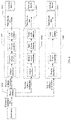
- FIG. 1 is a schematic diagram of an amplification function of a PA according to this application.
- FIG. 2 is a schematic architectural diagram of a communications system according to this application.
- FIG. 3 is a schematic diagram of a signal transmission method according to this application.
- FIG. 4 is a flowchart of a signal transmission method according to this application.
- FIG. 5 is a flowchart of a signal transmission method according to this application.
- FIG. 6A is a flowchart of determining time domain data according to this application.
- FIG. 6B is another flowchart of determining time domain data according to this application.
- FIG. 6C is another flowchart of determining time domain data according to this application.
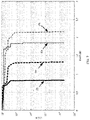
- FIG. 7 is a schematic simulation diagram according to this application.
- FIG. 8 is a flowchart of another signal transmission method according to this application.
- FIG. 9A is a schematic structural diagram of an apparatus according to this application.
- FIG. 9B is a schematic structural diagram of another apparatus according to this application.
- FIG. 10 is a schematic structural diagram of an apparatus according to this application.
- a signal transmission method provided in the embodiments of this application may be applied to a communications system.
- the communications system in the embodiments of this application may be various communications systems, for example, long term evolution (LTE), LTE-Advanced, a new radio (NR) system, narrowband IoT (narrowband internet of things, NB-IoT), or an enhanced machine type communication (eMTC) system; or may be a hybrid architecture of a plurality of communications systems, for example, a hybrid architecture of LTE and 5G.
- NR may also be referred to as a fifth-generation mobile communications system.
- An architecture of the communications system in the embodiments of this application may include communications devices, as shown in FIG. 2 .
- the communications devices may include a network device and a terminal device.
- the network device may also be referred to as a network-side device.
- the communications devices may perform wireless communication by using an air interface resource.
- the air interface resource may include at least one of a time domain resource, a frequency domain resource, a code resource, and a space resource.
- “at least one” may also be described as “one or more”, and “plurality” may be two, three, four, or more. This is not limited in this application.
- the technical solutions provided in the embodiments of this application may be applied to wireless communication between communications devices.
- the wireless communication between the communications devices may include wireless communication between a network device and a terminal device, wireless communication between network devices, and wireless communication between terminal devices.
- wireless communication may also be referred to as “communication” for short, and the term “communication” may also be described as “data transmission”, “signal transmission”, “information transmission”, “transmission”, or the like.
- transmission may include sending or receiving.
- the transmission may be uplink transmission, for example, a terminal device may send a signal to a network device; or the transmission may be downlink transmission, for example, a network device may send a signal to a terminal device.
- the terminal device in the embodiments of this application may also be referred to as a terminal, and may be a device with a wireless sending/receiving function.
- the terminal may be deployed on land, including an indoor or outdoor scenario and a handheld or vehicle-mounted scenario, or may be deployed on water (for example, on a steamship), or may be deployed in the air (for example, on an airplane, a balloon, or a satellite).
- the terminal device may be user equipment (UE).
- the UE includes a handheld device, a vehicle-mounted device, a wearable device, or a computing device that has a wireless communication function.
- the UE may be a mobile phone, a tablet computer, or a computer with a wireless sending/receiving function.
- the terminal device may be a virtual reality (VR) terminal device, an augmented reality (AR) terminal device, a wireless terminal in industrial control, a wireless terminal in self-driving, a wireless terminal in remote medical, a wireless terminal in a smart grid, a wireless terminal in a smart city, a wireless terminal in a smart home, or the like.
- an apparatus configured to implement a function of a terminal may be the terminal, or may be an apparatus that can support the terminal in implementing the function, for example, a chip system.
- the chip system may include a chip, or may include a chip and another discrete device.
- the network device in the embodiments of this application includes a base station (BS).
- the base station may be a device that is deployed in a radio access network and that can wirelessly communicate with a terminal.
- the base station may be in a plurality of forms, for example, a macro base station, a micro base station, a relay station, and an access point.
- the base station in the embodiments of this application may be a base station in 5G or a base station in LTE.
- the base station in 5G may also be referred to as a transmission reception point (TRP) or a gNB (gNodeB).
- TRP transmission reception point
- gNodeB gNodeB
- an apparatus configured to implement a function of a network device may be the network device; or may be an apparatus that can support the network device in implementing the function, for example, a chip system.
- the technical solutions provided in the embodiments of this application are described by using an example in which an apparatus configured to implement a function of a network device is the network device, and the network device is a base station.
- the technical solutions may be applied to various access technologies.
- the technical solutions may be applied to an orthogonal multiple access (OMA) technology or a non-orthogonal multiple access (NOMA) technology.
- OMA orthogonal multiple access
- NOMA non-orthogonal multiple access
- the technical solutions may be applied to orthogonal frequency division multiple access (OFDMA), single carrier frequency division multiple access (SC-FDMA), or other technologies. This is not limited in the embodiments of this application.
- the technical solutions may be applied to sparse code multiple access (SCMA), multi-user shared access (MUSA), pattern division multiple access (PDMA), interleave-grid multiple access (IGMA), resource spreading multiple access (RSMA), non-orthogonal coded multiple access (NCMA), non-orthogonal coded access (NOCA), or other technologies. This is not limited in the embodiments of this application.
- SCMA sparse code multiple access
- MUSA multi-user shared access
- PDMA pattern division multiple access
- IGMA interleave-grid multiple access
- RSMA resource spreading multiple access
- NCMA non-orthogonal coded multiple access
- NOCA non-orthogonal coded access
- the technical solutions may be applied to various types of scheduling.
- the technical solutions may be applied to grant-based scheduling or grant-free scheduling.
- grant-based scheduling a network device may send scheduling information to a terminal device by using dynamic signaling.
- the scheduling information carries a transmission parameter.
- the network device and the terminal device perform data transmission based on the transmission parameter.
- grant-free scheduling scheduling information may be preconfigured, or a network device may send scheduling information to a terminal device by using semi-static signaling.
- the scheduling information carries a transmission parameter.
- the network device and the terminal device perform data transmission based on the transmission parameter.
- the grant-free scheduling may also be referred to as non-dynamic scheduling, a non-dynamic grant, or another name. This is not limited in the embodiments of this application.
- a function of amplifying a signal by the PA includes a linear region and a non-linear region. As shown in FIG. 1 , when a power of an input signal is comparatively low, the input signal corresponds to the linear region of the PA; or when a power of an input signal is comparatively high, the input signal corresponds to the non-linear region of the PA.
- an amplification gain of the PA is a constant, that is, a power ratio of the pre-amplification input signal to an amplified output signal is a constant, and phases of the input signal and the output signal are the same.
- an amplification gain of the PA decreases with an increase in the power of the input signal, and the PA even has no amplification effect.
- a waveform distortion degree of the time domain data is directly proportional to a PAPR of the time domain data. To be specific, a higher PAPR of the time domain data indicates a more serious distortion exerted on the time domain data after the time domain data undergoes non-linear PA.
- a transmit end sends a signal by using a single carrier frequency domain multiple access (SC-FDMA) waveform obtained through Pi/2-binary phase shift keying (BPSK) modulation.
- SC-FDMA single carrier frequency domain multiple access
- BPSK Pi/2-binary phase shift keying
- FIG. 3 modulated data obtained through Pi/2-BPSK modulation is used as to-be-sent data, Fourier transform is performed on the to-be-sent data to obtain frequency domain data, and then frequency domain filtering, resource mapping, and inverse Fourier transform are performed on the frequency domain data to obtain time domain data, that is, the to-be-sent data generates the SC-FDMA waveform and is filtered by using a filter, where the filtering may be alternatively time domain filtering.
- SC-FDMA single carrier frequency domain multiple access
- BPSK Pi/2-binary phase shift keying
- a PAPR of the signal can be reduced to approximately 2 dB by sending the signal by using the SC-FDMA waveform obtained through Pi/2-BPSK modulation.
- reducing a PAPR of a signal to approximately 2 dB does not satisfy a system requirement.
- phase rotation is performed on modulated data, and when phase rotation is performed on the modulated data, a phase factor for performing phase rotation is determined by a length of the modulated data, so that a PAPR of time domain data corresponding to the modulated data can be lower, thereby reducing a waveform distortion degree of the time domain data after the time domain data passes through a PA, increasing a power of an output signal obtained after the time domain data passes through the PA, and improving demodulation performance of a receive end.
- a PAPR of output data obtained through frequency domain filtering may be less than 2 dB after the output data is converted to time domain.
- the method and the apparatus are based on a same invention concept. Because problem-resolving principles of the method and the apparatus are similar, mutual reference may be made to implementations of the apparatus and the method, and repeated content is not described in detail.
- “plurality” means at least two.
- the term “and/or” describes an association relationship between associated objects and represents that three relationships may exist.
- a and/or B may represent the following three cases: Only A exists, both A and B exist, and only B exists.
- the character “/” generally indicates an “or” relationship between associated objects.
- technical features in the type of technical feature are distinguished by using “first”, “second”, “third”, “A”, “B”, “C”, “D”, and the like. There is no chronological order or order of size between the technical features described by using the “first”, “second”, “third”, “A”, “B”, “C”, and “D”.
- Signaling in the embodiments of this application may be semi-static signaling, or may be dynamic signaling.
- the semi-static signaling may be radio resource control (RRC) signaling, a broadcast message, a system message, a medium access control (MAC) control element (CE), or the like.
- the broadcast message may include remaining minimum system information (RMSI).
- the dynamic signaling may be physical layer signaling.
- the physical layer signaling may be signaling carried on a physical control channel or signaling carried on a physical data channel.
- the physical data channel may be a downlink channel, for example, a physical downlink shared channel (PDSCH).
- PDSCH physical downlink shared channel
- the physical control channel may be a physical downlink control channel (PDCCH), an enhanced physical downlink control channel (EPDCCH), a narrowband physical downlink control channel (NPDCCH), or a machine type communication physical downlink control channel (MTC PDCCH, MPDCCH).
- the signaling carried on the PDCCH or the EPDCCH may also be referred to as downlink control information (DCI).
- DCI downlink control information
- the physical control channel may also be a physical sidelink control channel, and signaling carried on the physical sidelink control channel may also be referred to as sidelink control information (SCI).
- a symbol generally includes a cyclic prefix (CP) and time domain data of a time period.
- a symbol may be expressed as s(t), and duration is (N cp +N) ⁇ T s .
- time domain data that is in s(t) and that has a time range of 0 ⁇ t ⁇ N cp ⁇ T s may be considered as a CP
- time domain data that is in s(t) and that has a time range of N cp ⁇ T s ⁇ t ⁇ (N cp +N) ⁇ T s is time domain data of a time period N ⁇ T s , where T s is a time unit factor.
- T s may be a time interval between two pieces of adjacent discrete data in discrete data obtained by performing discrete sampling on consecutive time domain output data s(t).
- N 2048
- N cp 160 or 144
- T s is 1/(15000 ⁇ 2048) seconds
- a symbol includes a cyclic prefix and time domain data with a duration of approximately 66.7 microseconds.
- Resource element A resource element is a minimum physical resource, and is generally a minimum resource for carrying data.
- One resource element corresponds to one subcarrier in frequency domain, and corresponds to one symbol in time domain, that is, is located in one symbol. Therefore, a location of a resource element may be determined by using a symbol index and a subcarrier index.
- one RE may carry one piece of complex data. For example, for an orthogonal frequency division multiplexing (OFDM) waveform, one RE carries one piece of modulated data; and for an SC-FDMA waveform, one RE carries one piece of data in output data obtained by performing Fourier transform on modulated data.
- OFDM orthogonal frequency division multiplexing
- SC-FDMA SC-FDMA
- Resource block A resource block is a set of a plurality of resource elements.
- a resource block generally includes a plurality of consecutive subcarriers in frequency domain.
- One resource block may also include a plurality of consecutive symbols in time domain. For example, in an LTE system, one resource block includes 7 or 6 consecutive symbols in time domain, and includes 12 consecutive subcarriers in frequency domain. In other words, one resource block in the LTE system includes 84 or 72 resource elements.
- the signal transmission method provided in the embodiments of this application may be applied to a transmit end to send data to a receive end on a channel.
- the receive end may receive, on the channel, the data sent by the transmit end.
- Various possible physical channels or signals may be transmitted on the channel, for example, a broadcast channel (physical broadcast channel, PBCH), a primary synchronization signal (PSS), a secondary synchronization signal (SSS), a physical downlink shared channel (PDSCH), a physical downlink control channel (PDCCH), a physical uplink shared channel (PUSCH), a physical uplink control channel (PUCCH), various types of uplink reference signals (RS), various types of downlink RSs, or other possible physical channels.
- PBCH primary broadcast channel
- PSS primary synchronization signal
- SSS secondary synchronization signal
- PDSCH physical downlink shared channel
- PDCCH physical downlink control channel
- PUSCH physical uplink shared channel
- PUCCH physical uplink control channel
- RS uplink reference signals
- FIG. 4 is a flowchart of a signal transmission method according to an embodiment of this application.
- the signal transmission method provided in this embodiment of this application may be applied to a transmit end, a chip, a chipset, a functional module that is in a chip and that performs the method, or the like.
- the transmit end may be a terminal device, or may be a network device.
- the following describes the signal transmission method provided in this embodiment of this application by using an example in which a transmit end is a terminal device and a receive end is a network device. The method includes the following steps.
- a terminal device separately performs phase rotation on M pieces of modulated data to obtain M pieces of phase-rotated data, where a phase factor used for performing phase rotation on the M pieces of modulated data is determined based on a quantity M of pieces of the modulated data.
- the M pieces of modulated data mean that a length of the modulated data is M. Therefore, the phase factor for performing phase rotation on the M pieces of modulated data may be determined based on the length of the modulated data.
- the M pieces of modulated data may be obtained by the terminal device by modulating to-be-sent bit data.
- the to-be-sent bit data may be obtained in the following processing manner, but not limited thereto:
- the to-be-sent bit data may be obtained by performing processing such as encoding, interleaving, and scrambling on an original bit stream.
- the original bit stream may be obtained based on a service to be sent by the terminal device. This is not limited in this embodiment of this application.
- a value of M may be equal to a quantity of pieces of modulated data allocated by the terminal device to one symbol, or may be equal to a quantity of subcarriers included in allocated bandwidth.
- the terminal device uses an OFDM waveform as an example, the terminal device sends data on 10 symbols, and bandwidth allocated to each symbol is 1 RB, that is, 12 subcarriers. Therefore, the 10 symbols correspond to 120 REs.
- the terminal device may map one piece of modulated data to each RE, and send the modulated data to a network device on the RE.
- a quantity of pieces of modulated data transmitted on one symbol is 12, that is, M may be equal to 12.
- the to-be-sent bit data includes 120 pieces of bit data, and a modulation scheme is BPSK modulation.
- the terminal device performs BPSK modulation on the 120 pieces of bit data to obtain 120 pieces of modulated data.
- the 120 pieces of modulated data may be divided into 10 groups, and each group includes 12 pieces of modulated data.
- the 10 groups of modulated data are in a one-to-one correspondence with modulated data of the 10 symbols.
- modulated data of a group with an index 0 is modulated data of a symbol with an index 0
- modulated data of a group with an index 1 is modulated data of a symbol with an index 1, and so on.
- modulated data of each symbol may be separately processed.
- the symbol may be any one of one or more symbols used by the terminal device to transmit data, or the symbol may be any one of symbols included in a plurality of slots or a plurality of subframes of the terminal device.
- a reference signal in addition to data, a reference signal (RS) may also be sent in a complete data transmission process, and the reference signal may also be referred to as a pilot signal.
- the reference signal is a signal known to both the terminal device and the network device, and is mainly used to assist a receive end in demodulating data. Therefore, the reference signal may also be referred to as a demodulation reference signal (DMRS).
- DMRS demodulation reference signal
- SC-FDMA single carrier frequency division multiple access
- ZC sequence Zadoff-Chu sequence
- the reference signal and the data are located in different symbols, and occupy same bandwidth in frequency domain.
- the network device After the terminal device sends the data and the reference signal, and the network device receives the corresponding data and reference signal, the network device performs operations such as channel estimation and interpolation by using the known reference signal to estimate a channel response of a symbol in which the data is located, and then performs operations such as equalization and demodulation by using the received data and the estimated channel response to obtain the sent data through demodulation.
- the to-be-sent bit data may be unknown data that needs to be demodulated by the network device.
- the to-be-sent bit data may be a reference signal (for example, a DMRS), and the reference signal is data known to the network device, and is used to assist the network device in demodulating unknown data.
- the reference signal may be obtained by using a pseudo-random sequence, for example, a Gold sequence or a pseudo-noise (PN) sequence, but not limited thereto.
- An initial value of the pseudo-random sequence may be preconfigured by the terminal device, or an initial value of the pseudo-random sequence may be obtained by the terminal device according to a predefined rule, or an initial value of the pseudo-random sequence may be determined by the terminal device based on an identifier of the terminal device, or an initial value of the pseudo-random sequence may be notified by the network device to the terminal device by using signaling.
- the M pieces of modulated data in this embodiment of this application may be preconfigured, or may be notified by the network device to the terminal device by using signaling.
- the M pieces of modulated data may serve as DMRSs to assist the network device in demodulating unknown data.
- a modulation scheme for modulating the M pieces of to-be-sent bit data by the terminal device may be binary phase shift keying (BPSK). Therefore, the obtained M pieces of modulated data are BPSK modulated data.
- a data feature of the BPSK modulated data is that two pieces of adjacent BPSK modulated data have a same amplitude and a phase difference of 0 or ⁇ . Therefore, if modulated data with an index 0 is 1, modulated data with an index 1 may be 1 or ⁇ 1, modulated data with an index 2 may be 1 or ⁇ 1, and so on. That the phase difference between two pieces of adjacent modulated data is 0 or g satisfies BPSK modulation.
- output BPSK modulated data obtained according to Table 1 (a) is [1, 1, 1, ⁇ 1, ⁇ 1, ⁇ 1, 1, 1, ⁇ 1, 1, ⁇ 1].
- e j ⁇ m is the phase factor corresponding to the modulated data with the index m
- a and h are integers
- ⁇ ⁇ J indicates a round-down operation
- values of A and h may be preconfigured on the terminal device, or values of A and h may be obtained by the terminal device according to a predefined rule, or values of A and h may be notified by the network device to the terminal device by using signaling, for example, a value of A may be 1, ⁇ 1, 3, or ⁇ 3.
- M is equal to 3.
- phase factors [e j ⁇ 0 , e j ⁇ 1 , e j ⁇ 2 ] corresponding to three pieces of modulated data may be expressed as [1, 1, 1].
- the phase factor corresponding to the modulated data with the index m may be alternatively indicated by the network device to the terminal device by using signaling.
- the phase factor corresponding to the modulated data d(m) with the index m may be alternatively determined based on the length M of the modulated data and a symbol index of a symbol corresponding to the M pieces of modulated data.
- the symbol index of the symbol in which the M pieces of modulated data are located is l.
- phase rotation is performed on the modulated data to obtain the phase-rotated data
- the phase factor for performing phase rotation on the modulated data is determined by the length M of the modulated data.
- modulated data with different lengths has corresponding phase factors, so that a PAPR of time domain data corresponding to the modulated data can be lower, thereby reducing a waveform distortion degree of the time domain data after the time domain data passes through a PA, increasing a power of an output signal obtained after the time domain data passes through the PA, and improving demodulation performance of a receive end.
- the signal transmission method provided in this embodiment of this application is applicable to BPSK modulated data with all lengths.
- the terminal device determines time domain data based on the M pieces of phase-rotated data.
- the terminal device may determine the time domain data in any one of the following three manners.
- a process of a manner 1 is as follows.
- the terminal device performs M-point Fourier transform on the M pieces of phase-rotated data to obtain M pieces of frequency domain data, where a length of the Fourier transform may be the same as the length of the modulated data, and both are M.
- the Fourier transform may be discrete Fourier transform (DFT) or fast Fourier transform (FFT), or may be another form of Fourier transform. This is not specifically limited in this embodiment of this application. For example, this may be implemented by using the following formula:
- M scale fft is a coefficient used to adjust a power of output data obtained through Fourier transform
- M scale fft is a real number, for example, M scale fft may be equal to M
- d fre (k) is frequency domain data with an index k.
- the terminal device performs frequency domain filtering on the M pieces of frequency domain data to obtain M pieces of filtered frequency domain data.
- the frequency domain filtering may be implemented in the following manner: The terminal device multiplies the frequency domain data with the index k by a filter coefficient with an index k in a frequency domain filter, to obtain filtered frequency domain data with an index k.
- d filter (k) is the filtered frequency domain data with the index k
- d fre (k) is the frequency domain data with the index k
- S filter (k) is the filter coefficient with the index k in the frequency domain filter.
- the terminal device may determine the frequency domain filter in an initial filter including KXM filter coefficients, where the frequency domain filter includes M filter coefficients.
- K may be determined based on the length of the modulated data, that is, a length of the frequency domain data, namely, M.
- B may be set to 1. In this case, for a specific value of M, a determined value of K is the smallest.
- K may be alternatively determined in another manner. Examples are not listed one by one herein.
- the terminal device may extract the M filter coefficients from the KXM filter coefficients in the initial filter at a step of K, to obtain the frequency domain filter.
- S filter (m) indicates the filter coefficient with the index m in frequency domain filter coefficients
- S base ((A ⁇ K ⁇ M/h)mod K+m ⁇ K) indicates a filter coefficient with an index (A ⁇ K ⁇ M/h)mod K+m ⁇ K in the initial filter.
- an extraction operation is performed on the initial filter to obtain the frequency domain filter.
- the generated frequency domain filter is orthogonal.
- frequency domain filtering is performed on the M pieces of frequency domain data, interference caused by the frequency domain filtering operation can be reduced. Therefore, during ideal channel estimation with a known noise, the network device can correctly demodulate the modulated data.
- a coefficient of the frequency domain filter may be alternatively notified by the network device to the terminal device by using signaling.
- the terminal device may quantize a filter coefficient.
- the network device may indicate, by using signaling, quantized values corresponding to the coefficients.
- log 2 ( ⁇ N weight ⁇ ) bits of signaling may be used to indicate a value of the coefficient. Therefore, signaling including M ⁇ log 2 ( ⁇ N weight ⁇ ) bits is required for the M frequency domain filter coefficients.
- each integer place and each decimal place of the coefficient are separately indicated by using signaling.
- the frequency domain filter coefficients are normalized, and each coefficient is indicated by using one integer place and two decimal places. If a value of the integer place is 0 or 1, signaling including one bit is required for one integer place. A value of each of the two decimal places is 0 to 9, and signaling including four bits is required for indicating the value of each decimal place.
- the terminal device performs inverse Fourier transform on the M pieces of filtered frequency domain data to obtain the time domain data. Further, a cyclic prefix addition operation may be further performed after the inverse Fourier transform is performed.
- the inverse Fourier transform may be inverse discrete Fourier transform (IDFT) or inverse fast Fourier transform (IFFT), or may be another form of inverse Fourier transform. This is not specifically limited in this embodiment of this application.
- the inverse Fourier transform and the cyclic prefix addition may be implemented by using the following formula:
- s(t) is data at a moment with an index t in the time domain data
- t start ⁇ t ⁇ t end , t start , t, and t end are real numbers
- t end ⁇ t start (N+N cp ) ⁇ T s .
- t start 0.
- t end (N+N cp ) ⁇ T s .
- N is a positive integer.
- N may be equal to 2048.
- T s is a time unit factor.
- T s may be a time interval between two pieces of adjacent discrete data in discrete data obtained by performing discrete sampling on the time domain data s(t).
- T s may be preconfigured by the terminal device, or T s may be notified by the network device to the terminal device by using signaling.
- N cp ⁇ T s is duration of time domain output data
- N cp ⁇ T s is duration of a cyclic prefix.
- ⁇ f is a subcarrier spacing.
- t off may be ⁇ N cp ⁇ T s .
- a value of t offset may be preconfigured by the terminal device; or a value of t offset may be notified by the network device to the terminal device by using signaling.
- N scale ifft may be a coefficient for adjusting a power of output data in inverse Fourier transform.
- N scale ifft is a real number.
- N scale ifft 1.
- k re,offset is a frequency domain offset factor.
- k re,offset 1/2.
- a value of k re,offset may be preconfigured by the terminal device, or a value of k re,offset may be notified by the network device to the terminal device by using signaling.
- k sc start is an index of a starting location of a frequency domain resource to which the M pieces of filtered frequency domain data are mapped
- k sc end is an index of an ending location of the frequency domain resource to which the M pieces of filtered data are mapped
- k sc end ⁇ k sc start M ⁇ 1.
- k sc start ⁇ M/2 ⁇
- k sc end ⁇ M/2 ⁇ 1.
- the index of the starting location of the frequency domain resource and the index of the ending location of the frequency domain resource may be respectively a starting location and an ending location of a subcarrier corresponding to allocated bandwidth.
- indexes of the 48 subcarriers indicated by k sc start and k sc end may be expressed as k sc start mod N,(k sc start +1)mod N,(k sc start +2)mod N, . . . , (k sc start +47)mod N.
- duration of the time domain data is (N+N cp ) ⁇ T s .
- Starting data with a duration of N cp ⁇ T s may be considered as a cyclic prefix of the time domain data.
- Remaining data, with a length of N ⁇ T s , that is obtained by removing the starting data with the duration of N cp ⁇ T s may be considered as time domain output data without the cyclic prefix.
- the time domain data s ⁇ T s ) in the foregoing discrete representation form includes N+N cp pieces of data, where starting N cp pieces of data may be considered as a cyclic prefix.
- a process of a manner 2 is as follows.
- the terminal device performs M-point Fourier transform on the M pieces of phase-rotated data to obtain M pieces of frequency domain data.
- M-point Fourier transform on the M pieces of phase-rotated data.
- the terminal device performs inverse Fourier transform on the M pieces of frequency domain data to obtain time domain output data.
- the performing inverse Fourier transform on the M pieces of frequency domain data may be implemented by using the following formula:
- d time (t) is data at a moment with an index t in the time domain output data
- t start ⁇ t ⁇ t end , t start , t, and t end are real numbers
- t end ⁇ t start N ⁇ T s .
- t start ⁇ 0.
- t end N ⁇ T s
- ⁇ t offset is a delay offset, and a value of t offset may be 0.
- parameters such as ⁇ f, T s , N scale ifft , k re,offset , k sc start and k sc end refer to the descriptions of parameters such as ⁇ f, T s , N scale ifft , k re,offset , k sc start and k sc end in the manner 1. Details are not described herein again.
- duration of the time domain output data is N ⁇ T s , and the time domain output data does not have a cyclic prefix.
- the terminal device performs time domain filtering on the time domain output data with the duration of N ⁇ T s to obtain filtered time domain data with a duration of N ⁇ T s .
- the terminal device may perform circular convolution on the time domain output data and a time domain filter to obtain the filtered time domain data.
- the frequency domain filter in the manner 1 may be obtained by performing Fourier transform on the time domain filter.
- s′ filter (t) is data at a moment with an index t in a time domain filter s′ filter
- duration of the time domain filter s′ filter is N filter ⁇ T s .
- Fourier transform may be performed to obtain the frequency domain filter S filter in the manner 1.
- the time domain filter in the manner 2 may also be obtained by performing inverse Fourier transform on the frequency domain filter in the manner 1.
- the time domain filter for the time domain filtering may be obtained by the terminal device by performing inverse Fourier transform on the frequency domain filter.
- a manner of determining the frequency domain filter refer to the manner of determining the frequency domain filter in the manner 1. Details are not described herein again.
- the time domain filter for the time domain filtering may be alternatively determined based on signaling from the network device.
- the terminal device may quantize a filter coefficient.
- the network device may indicate, by using signaling, quantized values corresponding to the coefficients.
- log 2 ( ⁇ N weight ⁇ ) bits of signaling may be used to indicate a value of the coefficient. Therefore, signaling including N filter ⁇ log 2 ( ⁇ N weight ⁇ ) bits is required for the N filter time domain filter coefficients.
- each integer place and each decimal place of the coefficient are separately indicated by using signaling.
- the time domain filter coefficients are normalized, and each coefficient is indicated by using one integer place and two decimal places.
- a value of the integer place is 0 or 1
- signaling including one bit is required for the integer place.
- a value of each of the two decimal places is 0 to 9, and signaling including four bits is required for indicating the value of each decimal place.
- a time domain filter coefficient may be less than 0. Therefore, for any one of the N filter time domain filter coefficients, additional 1-bit signaling of signaling may be used to indicate whether the coefficient is greater than 0 or less than 0.
- integer place, the decimal place, and the quantization precision in the foregoing signaling indication manner are merely examples for description, and other possible values are not excluded.
- the terminal device adds a cyclic shift to the filtered time domain data with the duration of N ⁇ T s to obtain the time domain data.
- ending data with a duration of N cp ⁇ T s in the filtered time domain data is copied to a starting location of the filtered time domain data as a cyclic prefix, to obtain time domain transmit data with a duration of (N N cp ) ⁇ T s .
- a process of a manner 3 is as follows.
- the terminal device performs M-point Fourier transform on the M pieces of phase-rotated data to obtain M pieces of frequency domain data.
- M-point Fourier transform on the M pieces of phase-rotated data.
- the terminal device performs inverse Fourier transform on the M pieces of frequency domain data to obtain the time domain data.
- inverse Fourier transform on the M pieces of frequency domain data.
- the terminal device sends the time domain data to the network device.
- the terminal device may further amplify the time domain data by using a PA.
- the phase factor for performing phase rotation is determined by the length of the modulated data.
- modulated data with different lengths has corresponding phase factors, so that a PAPR of time domain data corresponding to the modulated data can be lower, thereby reducing a waveform distortion degree of the time domain data after the time domain data passes through a PA, increasing a power of an output signal obtained after the time domain data passes through the PA, and improving demodulation performance of a receive end.
- a horizontal axis indicates a PAPR value
- a vertical axis indicates a complementary cumulative distribution function (CCDF).
- a curve 1 shows a PAPR of an SC-FDMA waveform of three pieces of BP SK modulated data.
- a curve 2 shows a PAPR of a time domain data waveform, obtained by using the method provided in this embodiment of this application, of three pieces of BPSK modulated data.
- a curve 3 shows a PAPR of time domain data obtained by performing frequency domain filtering on an SC-FDMA waveform of six pieces of Pi/2-BPSK modulated data by using a frequency domain filter.
- a curve 4 shows a PAPR of a time domain data waveform, obtained by using the method provided in this embodiment of this application, of six pieces of BPSK modulated data.
- a phase of modulated data is adjusted based on a phase factor corresponding to a length of the modulated data, so that a PAPR of time domain data corresponding to the modulated data can be lower, thereby reducing a waveform distortion degree of the time domain data after the time domain data passes through a PA, increasing a power of an output signal obtained after the time domain data passes through the PA, and improving demodulation performance of a receive end.
- frequency domain filtering an extraction operation is performed on the initial filter to obtain the frequency domain filter, so that the generated frequency domain filter is orthogonal.
- frequency domain filtering is performed on the M pieces of frequency domain data, interference caused by the frequency domain filtering operation can be further reduced. Therefore, during ideal channel estimation with a known noise, the network device can correctly demodulate the modulated data.
- FIG. 8 is a flowchart of another signal transmission method according to an embodiment of this application.
- the signal transmission method provided in this embodiment of this application may be applied to a transmit end, a chip, a chipset, a functional module that is in a chip and that performs the method, or the like.
- the transmit end may be a terminal device, or may be a network device.
- the following describes the signal transmission method provided in this embodiment of this application by using an example in which a transmit end is a terminal device and a receive end is a network device. The method includes the following steps.
- a terminal device performs Fourier transform on M pieces of modulated data to obtain M pieces of frequency domain data.
- M For a value of M, refer to the descriptions of M in step S 301 . Details are not described herein again.
- the terminal device performs a cyclic shift on the M pieces of frequency domain data to obtain M pieces of shifted frequency domain data, where a shift length for performing the cyclic shift on the frequency domain data is determined based on M.
- the M pieces of frequency domain data mean that a length of the frequency domain data is M. Therefore, the shift length for performing the cyclic shift on the M pieces of frequency domain data is determined based on the length of the frequency domain data.
- the terminal device may cyclically shift the M pieces of frequency domain data rightwards to obtain the M pieces of shifted frequency domain data.
- shifted frequency domain data d shift is obtained by cyclically shifting frequency domain data d fre rightwards by Q shift pieces of data; or when Q shift is a negative integer, shifted frequency domain data d shift is obtained by cyclically shifting frequency domain data d fre leftwards by Q shift pieces of data.
- a and h are integers, ⁇ ⁇ indicates a round-down operation, and values of A and h may be preconfigured on the terminal device, or values of A and h may be obtained by the terminal device according to a predefined rule, or values of A and h may be notified by the network device to the terminal device by using signaling, for example, a value of A may be 1, ⁇ 1, 3, or ⁇ 3.
- a value of h is 4, and a value of Q shift may be ⁇ M/4 ⁇ , ⁇ M/4 ⁇ , ⁇ 3M/4 ⁇ , or ⁇ 3M/4 ⁇ .
- the terminal may not perform a cyclic shift on the M pieces of frequency domain data.
- the cyclic shift is performed on the frequency domain data d fre with the length of M to obtain the shifted frequency domain data d shift with the length of M.
- the shift length of the cyclic shift is determined by the length M.
- modulated data with different lengths has corresponding shift lengths, so that a PAPR of time domain data corresponding to the modulated data can be lower, thereby reducing a waveform distortion degree of the time domain data after the time domain data passes through a PA, increasing a power of an output signal obtained after the time domain data passes through the PA, and improving demodulation performance of a receive end.
- the signal transmission method provided in this embodiment of this application is applicable to BPSK modulated data with all lengths.
- the terminal device determines time domain data based on the M pieces of shifted frequency domain data.
- the terminal device may sequentially perform frequency domain filtering and inverse Fourier transform on the M pieces of shifted frequency domain data to obtain the time domain data. Further, a cyclic prefix addition operation may be further performed after the inverse Fourier transform is performed.
- processes of the frequency domain filtering, the inverse Fourier transform, and the cyclic prefix addition refer to the processes of the frequency domain filtering, the inverse Fourier transform, and the cyclic prefix addition in the manner 1 of step S 303 . Details are not described herein again.
- the terminal device may sequentially perform inverse Fourier transform and time domain filtering on the M pieces of shifted frequency domain data to obtain the time domain data. Further, a cyclic prefix addition operation may be further performed after the time domain filtering is performed.
- processes of the inverse Fourier transform, the time domain filtering, and the cyclic prefix addition operation refer to the processes of the inverse Fourier transform, the time domain filtering, and the cyclic prefix addition operation in the manner 2 of step S 303 . Details are not described herein again.
- the terminal device may perform inverse Fourier transform on the M pieces of shifted frequency domain data to obtain the time domain data. Further, a cyclic prefix addition operation may be further performed after the time domain filtering is performed. For processes of the inverse Fourier transform and the cyclic prefix addition operation, refer to the processes of the inverse Fourier transform and the cyclic prefix addition operation in the manner 3 of step S 303 . Details are not described herein again.
- the terminal device sends the time domain data to the network device.
- the terminal device may further amplify the time domain data by using a PA.
- the cyclic shift is performed on the frequency domain data to implement an effect of performing phase rotation on the modulated data
- the shift length for performing the cyclic shift on the frequency domain data is determined based on the length of the frequency domain data, that is, the length of the modulated data. In this way, frequency domain data with different lengths has corresponding shift lengths.
- the cyclic shift is performed on the frequency domain data based on the shift length corresponding to the length of the frequency domain data, so that an effect of adjusting a phase of the modulated data based on a phase factor corresponding to the length of the modulated data can be implemented, and a PAPR of time domain data corresponding to the modulated data can be lower, thereby reducing a waveform distortion degree of the time domain data after the time domain data passes through a PA, increasing a power of an output signal obtained after the time domain data passes through the PA, and improving demodulation performance of a receive end.
- frequency domain filtering an extraction operation is performed on the initial filter to obtain the frequency domain filter, so that the generated frequency domain filter is orthogonal.
- frequency domain filtering is performed on the M pieces of frequency domain data, interference caused by the frequency domain filtering operation can be further reduced. Therefore, during ideal channel estimation with a known noise, the network device can correctly demodulate the modulated data.
- the transmit end may include a hardware structure and/or a software module, to implement the functions in a form of a hardware structure, a software module, or a combination of a hardware structure and a software module. Whether one of the foregoing functions is performed by using a hardware structure, a software module, or a combination of a hardware structure and a software module depends on particular applications and design constraints of the technical solutions.
- an embodiment of this application provides a signal transmission apparatus.
- the apparatus may be a transmit end, or may be a chip or a chipset in a transmit end, or a part, of a chip in a transmit end, that is configured to perform a related method and function, or may be another apparatus for implementing a function of the transmit end.
- a structure of the signal transmission apparatus may be shown in FIG. 9A , and the apparatus includes a phase rotation module 901 , a determining module 902 , and a sending module 903 .
- the phase rotation module 901 is configured to perform step S 301 in the method shown in FIG. 3 .
- the determining module 902 is configured to perform step S 302 in the method shown in FIG. 3 .
- the sending module 903 is configured to perform step S 303 in the method shown in FIG. 3 .
- a structure of the signal transmission apparatus may be shown in FIG. 9B , and the apparatus includes a Fourier transform module 1001 , a cyclic shift module 1002 , a determining module 1003 , and a sending module 1004 .
- the Fourier transform module 1001 is configured to perform step S 601 in the method shown in FIG. 8 .
- the cyclic shift module 1002 is configured to perform step S 602 in the method shown in FIG. 8 .
- the determining module 1003 is configured to perform step S 603 in the method shown in FIG. 8 .
- the sending module 1004 is configured to perform step S 604 in the method shown in FIG. 8 .
- the Fourier transform module 1001 is configured to perform step S 601 in the method shown in FIG. 8 .
- the cyclic shift module 1002 is configured to perform step S 602 in the method shown in FIG. 8 .
- the determining module 1003 is configured to perform step S 603 in the method shown in FIG. 8 .
- the module division in the embodiments of this application is an example, and is merely logical function division, and there may be other division manners in actual implementation.
- functional modules in the embodiments of this application may be integrated in one processor, or each of the modules may exist alone physically, or at least two modules may be integrated in one module.
- the integrated module may be implemented in a form of hardware, or may be implemented in a form of a software functional module.
- FIG. 10 shows an apparatus 100 according to an embodiment of this application.
- the apparatus 100 is configured to implement functions of the transmit end in the foregoing methods.
- the apparatus may be a transmit end, or may be an apparatus in a transmit end.
- the apparatus may be a chip system.
- the chip system may include a chip, or may include a chip and another discrete device.
- the apparatus 100 includes at least one processor 120 , configured to implement functions of the transmit end in the methods provided in the embodiments of this application.
- the processor 120 may separately perform phase rotation on M pieces of modulated data, and determine time domain data based on M pieces of phase-rotated data.
- the processor 120 may separately perform phase rotation on M pieces of modulated data, and determine time domain data based on M pieces of phase-rotated data.
- the processor 120 may perform Fourier transform on M pieces of modulated data, perform a cyclic shift on M pieces of frequency domain data, and determine time domain data based on M pieces of shifted frequency domain data.
- Fourier transform on M pieces of modulated data, perform a cyclic shift on M pieces of frequency domain data, and determine time domain data based on M pieces of shifted frequency domain data.
- the apparatus 100 may further include at least one memory 130 , configured to store program instructions and/or data.
- the memory 130 is coupled to the processor 120 .
- the coupling is indirect coupling or a communication connection between apparatuses, units, or modules, may be in an electrical, mechanical, or another form, and is used for information exchange between the apparatuses, the units, or the modules.
- the processor 120 and the memory 130 may perform an operation cooperatively.
- the processor 120 may execute the program instructions stored in the memory 130 . At least one of the at least one memory may be included in the processor.
- the apparatus 100 may further include a communications interface 110 , configured to communicate with another device by using a transmission medium, so that an apparatus used in the apparatus 100 may communicate with another device.
- the device may be a network device.
- the processor 120 sends and receives data by using the communications interface 110 , for example, sends time domain data to a receive end.
- the communications interface may be a transceiver, a bus, a bus interface, a circuit, or another apparatus that can implement a communication function. This is not limited in this application.
- FIG. 10 shows an example in which the communications interface 110 is a transceiver 110 .
- a specific connection medium between the transceiver 110 , the processor 120 , and the memory 130 is not limited.
- the memory 130 , the processor 120 , and the transceiver 110 are connected by using a bus 140 .
- the bus is represented by a bold line in FIG. 10 .
- a connection manner between other components is described merely as an example and does not constitute a limitation.
- the bus may be classified into an address bus, a data bus, a control bus, and the like. For ease of representation, only one thick line is used to represent the bus in FIG. 10 , but this does not mean that there is only one bus or only one type of bus.
- the processor may be a general-purpose processor, a digital signal processor, an application-specific integrated circuit, a field programmable gate array or another programmable logic device, a discrete gate or transistor logic device, or a discrete hardware component, and may implement or execute the methods, steps, and logical block diagrams disclosed in the embodiments of this application.
- the general purpose processor may be a microprocessor or any conventional processor or the like. The steps of the method disclosed with reference to the embodiments of this application may be directly performed by a hardware processor, or may be performed by using a combination of hardware in the processor and a software module.
- the memory may be a non-volatile memory, for example, a hard disk drive (HDD) or a solid-state drive (SSD); or may be a volatile memory, for example, a random access memory (RAM).
- the memory is any other medium that can be used to carry or store expected program code in a form of an instruction or a data structure and that can be accessed by a computer. However, this is not limited thereto.
- the memory in this embodiment of this application may be alternatively a circuit or any other apparatus that can implement a storage function, and is configured to store program instructions and/or data.
- the embodiments may be implemented completely or partially in a form of a computer program product.
- the computer program product includes one or more computer instructions.
- the computer may be a general-purpose computer, a dedicated computer, a computer network, a network device, user equipment, or other programmable apparatuses.
- the computer instructions may be stored in a computer-readable storage medium or may be transmitted from a computer-readable storage medium to another computer-readable storage medium.
- the computer instructions may be transmitted from a website, computer, server, or data center to another website, computer, server, or data center in a wired (for example, a coaxial cable, an optical fiber, or a digital subscriber line (DSL)) or wireless (for example, infrared, radio, or microwave) manner.
- the computer-readable storage medium may be any usable medium accessible by a computer, or a data storage device, such as a server or a data center, integrating one or more usable media.
- the usable medium may be a magnetic medium (for example, a floppy disk, a hard disk, or a magnetic tape), an optical medium (for example, a digital video disc (DVD)), a semiconductor medium (for example, an SSD), or the like.
Landscapes
- Engineering & Computer Science (AREA)
- Computer Networks & Wireless Communication (AREA)
- Signal Processing (AREA)
- Physics & Mathematics (AREA)
- Discrete Mathematics (AREA)
- General Physics & Mathematics (AREA)
- Mathematical Physics (AREA)
- Digital Transmission Methods That Use Modulated Carrier Waves (AREA)
Abstract
Description
e j×φ
ej×φ
S filter(m)=S base((A×K×M/h)mod K+m×K), where
d shift(k)=d fre((k−Q shift)mod M), where
S filter(m)=S base((A×K×M/h)mod K+m×K), where
e j×φ
S filter(m)=S base((A×K×M/h)mod K+m×K), where
d shift(k)=d fre((k˜Q shift)mod M), where
Q shift =└M×A/h┘, where
S filter(m)=S base((A×K×M/h)mod K+m×K), where
| TABLE 1 (a) | |||
| Input bit of a bit stream | Output modulated |
||
| 0 | 1 | ||
| 1 | −1 | ||
| TABLE 2 (b) | |||
| Input bit of a bit stream | Output modulated |
||
| 0 | −1 | ||
| 1 | 1 | ||
e j×φ
In this case, phase-rotated data obtained by performing phase rotation on the three pieces of modulated data is different from the modulated data. Therefore, if A=3, phase rotation needs to be performed on the three pieces of modulated data.
e j×φ
where
d filter(k)=d fre(k)×S filter(k), where
S filter(m)=S base((A×K×M/h)mod K+m×K), where
where
where
d shift(k)=d fre((k−Q shift)mod M), where
dshift(k) is the shifted frequency domain data with the index k in the M pieces of shifted frequency domain data, dfre((k−Qshift) mod M) is frequency domain data with an index (k−Qshift)mod M in the M pieces of frequency domain data, Qshift is the shift length, Qshift is an integer, and a value of Qshift may be preconfigured by the terminal device, or a value of Qshift may be notified by a network device to the terminal device by using signaling, or a value of Qshift may be obtained by the terminal device according to a predefined rule. It can be learned that, when Qshift is a positive integer, shifted frequency domain data dshift is obtained by cyclically shifting frequency domain data dfre rightwards by Qshift pieces of data; or when Qshift is a negative integer, shifted frequency domain data dshift is obtained by cyclically shifting frequency domain data dfre leftwards by Qshift pieces of data.
Q shift =└M×A/h┘, where
Claims (20)
e j×φ
S filter(m)=S base((A×K×M/h)mod K+m×K), wherein
e j×φ
S filter(m)=S base((A×K×M/h)mod K+m×K), wherein
e j×φ
S filter(m)=S base((A×K×M/h)mod K+m×K), wherein
Applications Claiming Priority (3)
| Application Number | Priority Date | Filing Date | Title |
|---|---|---|---|
| CN201811377847.6 | 2018-11-19 | ||
| CN201811377847.6A CN111200571B (en) | 2018-11-19 | 2018-11-19 | A kind of signal transmission method and device |
| PCT/CN2019/115803 WO2020103687A1 (en) | 2018-11-19 | 2019-11-05 | Signal transmission method and apparatus |
Related Parent Applications (1)
| Application Number | Title | Priority Date | Filing Date |
|---|---|---|---|
| PCT/CN2019/115803 Continuation WO2020103687A1 (en) | 2018-11-19 | 2019-11-05 | Signal transmission method and apparatus |
Publications (2)
| Publication Number | Publication Date |
|---|---|
| US20210288860A1 US20210288860A1 (en) | 2021-09-16 |
| US11368348B2 true US11368348B2 (en) | 2022-06-21 |
Family
ID=70746108
Family Applications (1)
| Application Number | Title | Priority Date | Filing Date |
|---|---|---|---|
| US17/324,873 Active US11368348B2 (en) | 2018-11-19 | 2021-05-19 | Signal transmission method and apparatus |
Country Status (4)
| Country | Link |
|---|---|
| US (1) | US11368348B2 (en) |
| EP (1) | EP3876489B1 (en) |
| CN (1) | CN111200571B (en) |
| WO (1) | WO2020103687A1 (en) |
Cited By (2)
| Publication number | Priority date | Publication date | Assignee | Title |
|---|---|---|---|---|
| US20220052896A1 (en) * | 2019-04-30 | 2022-02-17 | Huawei Technologies Co., Ltd. | Side Information Transmission Method Based on Partial Transmit Sequence Technology, and Apparatus |
| US20230308332A1 (en) * | 2022-03-23 | 2023-09-28 | Realtek Semiconductor Corp. | Communication Device and Method of Handling PAPR |
Families Citing this family (3)
| Publication number | Priority date | Publication date | Assignee | Title |
|---|---|---|---|---|
| CN111200571B (en) * | 2018-11-19 | 2021-10-01 | 华为技术有限公司 | A kind of signal transmission method and device |
| WO2020217941A1 (en) * | 2019-04-25 | 2020-10-29 | 日本電気株式会社 | Modulation device and demodulation device |
| CN114844752A (en) * | 2021-01-30 | 2022-08-02 | 华为技术有限公司 | Data sending method, data receiving method and related device |
Citations (79)
| Publication number | Priority date | Publication date | Assignee | Title |
|---|---|---|---|---|
| US6434188B1 (en) * | 1999-04-07 | 2002-08-13 | Legerity, Inc. | Differential encoding arrangement for a discrete multi-tone transmission system |
| US20030202460A1 (en) * | 2002-04-26 | 2003-10-30 | Samsung Electronics Co., Ltd. | Apparatus and method for transmitting and receiving side information of a partial transmit sequence in an OFDM communication system |
| US6928084B2 (en) * | 2000-03-28 | 2005-08-09 | At & T Corp. | OFDM communication system and method having a reduced peak-to-average power ratio |
| US20060072682A1 (en) * | 2004-10-06 | 2006-04-06 | Mark Kent | Method and system for pre-equalization in a single weight (SW) single channel (SC) multiple-input multiple-output (MIMO) system |
| US20060215784A1 (en) * | 2005-02-02 | 2006-09-28 | Samsung Electronics Co., Ltd. | Transmission apparatus and method for MIMO system |
| US20060269022A1 (en) * | 2005-05-31 | 2006-11-30 | Intel Corporation | Open loop MIMO receiver and method using hard decision feedback |
| US20070211816A1 (en) * | 2006-02-28 | 2007-09-13 | Samsung Electronics Co., Ltd. | Apparatus and method for transmitting and receiving signals in a multi-antenna system |
| US20080031375A1 (en) * | 2005-03-16 | 2008-02-07 | Liang Zhou | Wireless communication device and channel estimation and separation method in multi input system |
| US20090004984A1 (en) * | 2007-06-29 | 2009-01-01 | Qualcomm Incorporated | Enhanced frequency domain spreading |
| CN101374125A (en) | 2007-08-24 | 2009-02-25 | 大唐移动通信设备有限公司 | Method and apparatus for reducing PAR |
| US20090052577A1 (en) * | 2007-08-14 | 2009-02-26 | Lg Electronics Inc. | Peak to average power ratio reduction |
| US20090080454A1 (en) * | 2005-07-08 | 2009-03-26 | Nec Corporation | Signal Generating Apparatus and Signal Generation Method |
| US7529305B1 (en) * | 2000-10-27 | 2009-05-05 | Nortel Networks Limited | Combination of space-time coding and spatial multiplexing, and the use of orthogonal transformation in space-time coding |
| US20090196163A1 (en) * | 2006-07-05 | 2009-08-06 | Koninklijke Philips Electronics N.V. | Bandwidth asymmetric communication system based on ofdm and tdma |
| US20090245399A1 (en) * | 2006-04-20 | 2009-10-01 | Jung Hoon Lee | Method and apparatus for inserting guard interval in a mobile communication system |
| US7680210B2 (en) * | 2002-08-28 | 2010-03-16 | St-Ericsson Sa | Method for generating I/Q signal in a TDMA transmitter and corresponding modulator |
| US7720175B2 (en) * | 2005-08-10 | 2010-05-18 | Samsung Electronics Co., Ltd | Apparatus and method for reducing peak-to-average power ratio in an OFDM communication system |
| CN101753511A (en) | 2008-12-03 | 2010-06-23 | 株式会社Ntt都科摩 | Signal generation device and method |
| US20100239046A1 (en) * | 2007-09-03 | 2010-09-23 | Jin Young Chun | Method of Transmitting Data Using Repetition Coding |
| US20100260234A1 (en) * | 2009-04-09 | 2010-10-14 | Motorola, Inc. | Closed-loop transmission feedback in wireless communication systems |
| US20110116566A1 (en) * | 2008-08-08 | 2011-05-19 | Hiroki Takahashi | Wireless communication system, transmitter and receiver |
| US7969205B2 (en) * | 2007-04-13 | 2011-06-28 | Fujitsu Limited | Peak power reduction method |
| US20110228878A1 (en) * | 2008-11-27 | 2011-09-22 | Stefano Sorrentino | Methods and Arrangements for Peak to Average Power Ratio Reduction |
| US8204150B2 (en) * | 2007-10-01 | 2012-06-19 | Samsung Electronics Co., Ltd. | Apparatus and method for reducing peak-to-average power ratio in a wireless communication system |
| US8514695B2 (en) * | 2007-12-29 | 2013-08-20 | China Mobile Communications Corporation | Method and apparatus for wideband wireless transmission and transmission system |
| CN103326985A (en) | 2013-07-15 | 2013-09-25 | 浙江师范大学 | Method for reducing peak-to-mean ratio in OFDM (Orthogonal Frequency Division Multiplexing) |
| CN103458485A (en) | 2013-09-18 | 2013-12-18 | 济南大学 | Peak power optimization method in orthogonal frequency division multiplexing system and transmitting system thereof |
| CN103973629A (en) | 2014-05-27 | 2014-08-06 | 电子科技大学 | SLM (selective mapping) method for reducing PAPR (peak to average power ratio) of MIMO-OFDM (multiple input multiple output-orthogonal frequency division multiplexing) system |
| CN104022994A (en) | 2014-06-16 | 2014-09-03 | 电子科技大学 | PTS method for lowering PAPR of MIMO-OFDM system |
| US8831136B2 (en) * | 2012-03-30 | 2014-09-09 | Fujitsu Limited | Wireless apparatus and distortion compensating method |
| US8891674B2 (en) * | 2007-02-26 | 2014-11-18 | Samsung Electronics Co., Ltd. | Digital transmission system for transmitting additional data and method thereof |
| US8909686B2 (en) * | 2011-08-09 | 2014-12-09 | Fujitsu Limited | Discrete fourier calculation device, radio communication device, and discrete fourier calculation method |
| US8971170B2 (en) * | 2009-12-11 | 2015-03-03 | Fujitsu Limited | Wireless communication apparatus and wireless communication method |
| US8976878B2 (en) * | 2013-01-15 | 2015-03-10 | Raytheon Company | Polynomial phases for multi-carrier modulation schemes with time domain windowing |
| CN104639281A (en) | 2013-11-12 | 2015-05-20 | 华为技术有限公司 | Method, device and system for data transmission control |
| CN104780135A (en) | 2015-05-05 | 2015-07-15 | 临沂大学 | DFT-GCS-based visible light DCO-OFDM system peak-to-average ratio restraining method |
| US9160433B2 (en) * | 2012-07-31 | 2015-10-13 | Huawei Technologies Co., Ltd. | Beam codebook generation method, beam search method and related apparatuses |
| US20160094318A1 (en) * | 2001-04-26 | 2016-03-31 | Genghiscomm Holdings, LLC | Single-Carrier OFDMA |
| WO2016070330A1 (en) | 2014-11-04 | 2016-05-12 | 华为技术有限公司 | Ltf generation method and apparatus |
| CN105681241A (en) | 2016-01-06 | 2016-06-15 | 北京邮电大学 | Method and device for reducing peak-to-average power ratio of FBMC-OQAM signal |
| US20160182270A1 (en) * | 2013-08-30 | 2016-06-23 | Fraunhofer-Gesellschaft Zur Foerderung Der Angewandten Forschung E.V. | Method and apparatus for transmitting a signal |
| US9413499B2 (en) * | 2009-03-03 | 2016-08-09 | Ntt Docomo, Inc. | Code multiplexing transmission method, transmission apparatus and reception apparatus |
| CN106357585A (en) | 2016-09-07 | 2017-01-25 | 北京邮电大学 | Signal sending method and device |
| US9571140B2 (en) * | 2015-02-05 | 2017-02-14 | Nokia Solutions And Networks Oy | Space-time coding for zero-tail spread OFDM system in a wireless network |
| US9641374B2 (en) * | 2014-02-04 | 2017-05-02 | Huawei Technologies Co., Ltd. | Direct-detected orthogonal frequency-division multiplexing with dispersion pre-compensation digital signal processing |
| CN107040487A (en) | 2016-02-04 | 2017-08-11 | 中兴通讯股份有限公司 | Signal processing method and device |
| US9848342B1 (en) * | 2016-07-20 | 2017-12-19 | Ccip, Llc | Excursion compensation in multipath communication systems having performance requirements parameters |
| CN107800662A (en) | 2017-12-05 | 2018-03-13 | 上海无线电设备研究所 | A kind of method for reducing spread spectrum OFDM signal papr |
| US20180191410A1 (en) * | 2015-08-24 | 2018-07-05 | Huawei Technologies Co., Ltd. | Subset of w2 method and apparatus for sending precoding information and feeding back precoding information |
| US20180198668A1 (en) * | 2017-01-06 | 2018-07-12 | Samsung Electronics Co., Ltd. | Apparatus and method for reducing peak-to-average power ratio in wireless communication system |
| US10069666B2 (en) * | 2015-07-20 | 2018-09-04 | Telefonaktiebolaget Lm Ericsson (Publ) | Transceiver architecture that maintains legacy timing by inserting and removing cyclic prefix at legacy sampling rate |
| US20180324005A1 (en) * | 2017-05-04 | 2018-11-08 | Samsung Electronics Co., Ltd. | Method and apparatus for transmitting and receiving signal for low peak-to-average power ratio in wireless communication system |
| US20190013912A1 (en) * | 2015-12-25 | 2019-01-10 | Sharp Kabushiki Kaisha | Base station apparatus, terminal apparatus, and communication method |
| US20190081840A1 (en) * | 2017-09-11 | 2019-03-14 | Qualcomm Incorporated | Reference signal design for pi/2 binary phase shift keying modulation with frequency domain spectral shaping |
| US10263736B2 (en) * | 2015-04-07 | 2019-04-16 | China Academy Of Telecommunications Technology | Method and device for detecting data transmission and received signals |
| US20190116004A1 (en) * | 2016-04-19 | 2019-04-18 | Sharp Kabushiki Kaisha | Transmission device, reception device, and communication method |
| US20190132866A1 (en) * | 2016-04-07 | 2019-05-02 | Sharp Kabushiki Kaisha | Transmission device and reception device |
| US10312990B2 (en) * | 2015-09-02 | 2019-06-04 | Huawei Technologies Co., Ltd. | Signal sending or receiving method and device |
| US20190222456A1 (en) * | 2016-09-30 | 2019-07-18 | Huawei Technologies Co., Ltd. | Data processing method, apparatus, and system |
| US10404341B2 (en) * | 2011-04-19 | 2019-09-03 | Sun Patent Trust | Signal generating method and signal generating device |
| US20190273643A1 (en) * | 2016-09-30 | 2019-09-05 | Huawei Technologies Co., Ltd. | Data transmission method and communications device |
| US20190313398A1 (en) * | 2016-11-02 | 2019-10-10 | Ntt Docomo, Inc. | Transmitting apparatus and radio communication method |
| US10498423B2 (en) * | 2016-05-12 | 2019-12-03 | Huawei Technologies Co., Ltd. | Channel state information feedback method, precoding method, terminal device, and base station |
| US20200021414A1 (en) * | 2017-06-30 | 2020-01-16 | Huawei Technologies Co., Ltd. | Wireless Communication Method, Wireless Communications Apparatus, And Wireless Communications System |
| US10567062B2 (en) * | 2015-12-21 | 2020-02-18 | Huawei Technologies Co., Ltd | Downlink channel reconstruction method and apparatus |
| US20200059335A1 (en) * | 2017-06-30 | 2020-02-20 | Huawei Technologies Co., Ltd. | Sending method and apparatus |
| US20200067621A1 (en) * | 2017-06-16 | 2020-02-27 | Huawei Technologies Co., Ltd. | Wireless communication method and wireless communications apparatus |
| US10680870B2 (en) * | 2016-11-09 | 2020-06-09 | Huawei Technologies Co., Ltd. | Synthesis of near-constant modulus waveform for high frequency transmission |
| US20200204421A1 (en) * | 2017-08-29 | 2020-06-25 | Huawei Technologies Co., Ltd. | Efficient design and implementation of synthesis of near-constant modulus (storm) waveform |
| US10736073B2 (en) * | 2016-11-04 | 2020-08-04 | Huawei Technologies Co., Ltd. | SFN indication method, terminal device, and positioning server and system |
| US10778490B2 (en) * | 2016-09-30 | 2020-09-15 | Huawei Technologies Co., Ltd. | Reference signal transmission method and apparatus |
| US10790926B2 (en) * | 2016-06-14 | 2020-09-29 | Huawei Technologies Co., Ltd. | Data processing method, network device, and terminal |
| US20200328926A1 (en) * | 2017-12-30 | 2020-10-15 | Huawei Technologies Co., Ltd. | Data sending method and apparatus |
| US10904868B2 (en) * | 2018-04-06 | 2021-01-26 | Qualcomm Incorporated | Multi-layer resource spread multiple access with permuted power scaling and phase rotation |
| US11108605B2 (en) * | 2017-06-16 | 2021-08-31 | Huawei Technologies Co., Ltd. | Phase tracking reference signal processing method and apparatus |
| US20210281460A1 (en) * | 2018-11-19 | 2021-09-09 | Huawei Technologies Co., Ltd. | Data Transmission Method And Apparatus |
| US20210288855A1 (en) * | 2018-11-30 | 2021-09-16 | Huawei Technologies Co., Ltd. | Data stream multiplexing method and terminal |
| US20210288860A1 (en) * | 2018-11-19 | 2021-09-16 | Huawei Technologies Co., Ltd. | Signal transmission method and apparatus |
| US20220021570A1 (en) * | 2019-03-30 | 2022-01-20 | Huawei Technologies Co.,Ltd. | Data compression method and apparatus |
-
2018
- 2018-11-19 CN CN201811377847.6A patent/CN111200571B/en active Active
-
2019
- 2019-11-05 EP EP19887739.1A patent/EP3876489B1/en active Active
- 2019-11-05 WO PCT/CN2019/115803 patent/WO2020103687A1/en not_active Ceased
-
2021
- 2021-05-19 US US17/324,873 patent/US11368348B2/en active Active
Patent Citations (85)
| Publication number | Priority date | Publication date | Assignee | Title |
|---|---|---|---|---|
| US6434188B1 (en) * | 1999-04-07 | 2002-08-13 | Legerity, Inc. | Differential encoding arrangement for a discrete multi-tone transmission system |
| US6928084B2 (en) * | 2000-03-28 | 2005-08-09 | At & T Corp. | OFDM communication system and method having a reduced peak-to-average power ratio |
| US7529305B1 (en) * | 2000-10-27 | 2009-05-05 | Nortel Networks Limited | Combination of space-time coding and spatial multiplexing, and the use of orthogonal transformation in space-time coding |
| US20160094318A1 (en) * | 2001-04-26 | 2016-03-31 | Genghiscomm Holdings, LLC | Single-Carrier OFDMA |
| US20030202460A1 (en) * | 2002-04-26 | 2003-10-30 | Samsung Electronics Co., Ltd. | Apparatus and method for transmitting and receiving side information of a partial transmit sequence in an OFDM communication system |
| US7680210B2 (en) * | 2002-08-28 | 2010-03-16 | St-Ericsson Sa | Method for generating I/Q signal in a TDMA transmitter and corresponding modulator |
| US20060072682A1 (en) * | 2004-10-06 | 2006-04-06 | Mark Kent | Method and system for pre-equalization in a single weight (SW) single channel (SC) multiple-input multiple-output (MIMO) system |
| US20060215784A1 (en) * | 2005-02-02 | 2006-09-28 | Samsung Electronics Co., Ltd. | Transmission apparatus and method for MIMO system |
| US20080031375A1 (en) * | 2005-03-16 | 2008-02-07 | Liang Zhou | Wireless communication device and channel estimation and separation method in multi input system |
| US20060269022A1 (en) * | 2005-05-31 | 2006-11-30 | Intel Corporation | Open loop MIMO receiver and method using hard decision feedback |
| US20090080454A1 (en) * | 2005-07-08 | 2009-03-26 | Nec Corporation | Signal Generating Apparatus and Signal Generation Method |
| US7720175B2 (en) * | 2005-08-10 | 2010-05-18 | Samsung Electronics Co., Ltd | Apparatus and method for reducing peak-to-average power ratio in an OFDM communication system |
| US20070211816A1 (en) * | 2006-02-28 | 2007-09-13 | Samsung Electronics Co., Ltd. | Apparatus and method for transmitting and receiving signals in a multi-antenna system |
| US7924958B2 (en) * | 2006-02-28 | 2011-04-12 | Samsung Electronics Co., Ltd. | Apparatus and method for transmitting and receiving signals in a multi-antenna system |
| US20090245399A1 (en) * | 2006-04-20 | 2009-10-01 | Jung Hoon Lee | Method and apparatus for inserting guard interval in a mobile communication system |
| US20090196163A1 (en) * | 2006-07-05 | 2009-08-06 | Koninklijke Philips Electronics N.V. | Bandwidth asymmetric communication system based on ofdm and tdma |
| US8891674B2 (en) * | 2007-02-26 | 2014-11-18 | Samsung Electronics Co., Ltd. | Digital transmission system for transmitting additional data and method thereof |
| US7969205B2 (en) * | 2007-04-13 | 2011-06-28 | Fujitsu Limited | Peak power reduction method |
| US20090004984A1 (en) * | 2007-06-29 | 2009-01-01 | Qualcomm Incorporated | Enhanced frequency domain spreading |
| US20090052577A1 (en) * | 2007-08-14 | 2009-02-26 | Lg Electronics Inc. | Peak to average power ratio reduction |
| CN101374125A (en) | 2007-08-24 | 2009-02-25 | 大唐移动通信设备有限公司 | Method and apparatus for reducing PAR |
| US20100239046A1 (en) * | 2007-09-03 | 2010-09-23 | Jin Young Chun | Method of Transmitting Data Using Repetition Coding |
| US8204150B2 (en) * | 2007-10-01 | 2012-06-19 | Samsung Electronics Co., Ltd. | Apparatus and method for reducing peak-to-average power ratio in a wireless communication system |
| US8514695B2 (en) * | 2007-12-29 | 2013-08-20 | China Mobile Communications Corporation | Method and apparatus for wideband wireless transmission and transmission system |
| US20110116566A1 (en) * | 2008-08-08 | 2011-05-19 | Hiroki Takahashi | Wireless communication system, transmitter and receiver |
| US20110228878A1 (en) * | 2008-11-27 | 2011-09-22 | Stefano Sorrentino | Methods and Arrangements for Peak to Average Power Ratio Reduction |
| CN101753511A (en) | 2008-12-03 | 2010-06-23 | 株式会社Ntt都科摩 | Signal generation device and method |
| US9413499B2 (en) * | 2009-03-03 | 2016-08-09 | Ntt Docomo, Inc. | Code multiplexing transmission method, transmission apparatus and reception apparatus |
| US20100260234A1 (en) * | 2009-04-09 | 2010-10-14 | Motorola, Inc. | Closed-loop transmission feedback in wireless communication systems |
| US8971170B2 (en) * | 2009-12-11 | 2015-03-03 | Fujitsu Limited | Wireless communication apparatus and wireless communication method |
| US10404341B2 (en) * | 2011-04-19 | 2019-09-03 | Sun Patent Trust | Signal generating method and signal generating device |
| US8909686B2 (en) * | 2011-08-09 | 2014-12-09 | Fujitsu Limited | Discrete fourier calculation device, radio communication device, and discrete fourier calculation method |
| US8831136B2 (en) * | 2012-03-30 | 2014-09-09 | Fujitsu Limited | Wireless apparatus and distortion compensating method |
| US9160433B2 (en) * | 2012-07-31 | 2015-10-13 | Huawei Technologies Co., Ltd. | Beam codebook generation method, beam search method and related apparatuses |
| US8976878B2 (en) * | 2013-01-15 | 2015-03-10 | Raytheon Company | Polynomial phases for multi-carrier modulation schemes with time domain windowing |
| CN103326985A (en) | 2013-07-15 | 2013-09-25 | 浙江师范大学 | Method for reducing peak-to-mean ratio in OFDM (Orthogonal Frequency Division Multiplexing) |
| US20160182270A1 (en) * | 2013-08-30 | 2016-06-23 | Fraunhofer-Gesellschaft Zur Foerderung Der Angewandten Forschung E.V. | Method and apparatus for transmitting a signal |
| CN103458485A (en) | 2013-09-18 | 2013-12-18 | 济南大学 | Peak power optimization method in orthogonal frequency division multiplexing system and transmitting system thereof |
| CN104639281A (en) | 2013-11-12 | 2015-05-20 | 华为技术有限公司 | Method, device and system for data transmission control |
| US9641374B2 (en) * | 2014-02-04 | 2017-05-02 | Huawei Technologies Co., Ltd. | Direct-detected orthogonal frequency-division multiplexing with dispersion pre-compensation digital signal processing |
| CN103973629A (en) | 2014-05-27 | 2014-08-06 | 电子科技大学 | SLM (selective mapping) method for reducing PAPR (peak to average power ratio) of MIMO-OFDM (multiple input multiple output-orthogonal frequency division multiplexing) system |
| CN104022994A (en) | 2014-06-16 | 2014-09-03 | 电子科技大学 | PTS method for lowering PAPR of MIMO-OFDM system |
| WO2016070330A1 (en) | 2014-11-04 | 2016-05-12 | 华为技术有限公司 | Ltf generation method and apparatus |
| US9571140B2 (en) * | 2015-02-05 | 2017-02-14 | Nokia Solutions And Networks Oy | Space-time coding for zero-tail spread OFDM system in a wireless network |
| US10263736B2 (en) * | 2015-04-07 | 2019-04-16 | China Academy Of Telecommunications Technology | Method and device for detecting data transmission and received signals |
| CN104780135A (en) | 2015-05-05 | 2015-07-15 | 临沂大学 | DFT-GCS-based visible light DCO-OFDM system peak-to-average ratio restraining method |
| US10069666B2 (en) * | 2015-07-20 | 2018-09-04 | Telefonaktiebolaget Lm Ericsson (Publ) | Transceiver architecture that maintains legacy timing by inserting and removing cyclic prefix at legacy sampling rate |
| US20180191410A1 (en) * | 2015-08-24 | 2018-07-05 | Huawei Technologies Co., Ltd. | Subset of w2 method and apparatus for sending precoding information and feeding back precoding information |
| US10312990B2 (en) * | 2015-09-02 | 2019-06-04 | Huawei Technologies Co., Ltd. | Signal sending or receiving method and device |
| US10567062B2 (en) * | 2015-12-21 | 2020-02-18 | Huawei Technologies Co., Ltd | Downlink channel reconstruction method and apparatus |
| US20190013912A1 (en) * | 2015-12-25 | 2019-01-10 | Sharp Kabushiki Kaisha | Base station apparatus, terminal apparatus, and communication method |
| CN105681241A (en) | 2016-01-06 | 2016-06-15 | 北京邮电大学 | Method and device for reducing peak-to-average power ratio of FBMC-OQAM signal |
| CN107040487A (en) | 2016-02-04 | 2017-08-11 | 中兴通讯股份有限公司 | Signal processing method and device |
| US20190132866A1 (en) * | 2016-04-07 | 2019-05-02 | Sharp Kabushiki Kaisha | Transmission device and reception device |
| US20190116004A1 (en) * | 2016-04-19 | 2019-04-18 | Sharp Kabushiki Kaisha | Transmission device, reception device, and communication method |
| US10498423B2 (en) * | 2016-05-12 | 2019-12-03 | Huawei Technologies Co., Ltd. | Channel state information feedback method, precoding method, terminal device, and base station |
| US10790926B2 (en) * | 2016-06-14 | 2020-09-29 | Huawei Technologies Co., Ltd. | Data processing method, network device, and terminal |
| US9848342B1 (en) * | 2016-07-20 | 2017-12-19 | Ccip, Llc | Excursion compensation in multipath communication systems having performance requirements parameters |
| CN106357585A (en) | 2016-09-07 | 2017-01-25 | 北京邮电大学 | Signal sending method and device |
| US20190273643A1 (en) * | 2016-09-30 | 2019-09-05 | Huawei Technologies Co., Ltd. | Data transmission method and communications device |
| US20190222456A1 (en) * | 2016-09-30 | 2019-07-18 | Huawei Technologies Co., Ltd. | Data processing method, apparatus, and system |
| US10778490B2 (en) * | 2016-09-30 | 2020-09-15 | Huawei Technologies Co., Ltd. | Reference signal transmission method and apparatus |
| US10924315B2 (en) * | 2016-09-30 | 2021-02-16 | Huawei Technologies Co., Ltd. | Data transmission method and communications device |
| US20190313398A1 (en) * | 2016-11-02 | 2019-10-10 | Ntt Docomo, Inc. | Transmitting apparatus and radio communication method |
| US10736073B2 (en) * | 2016-11-04 | 2020-08-04 | Huawei Technologies Co., Ltd. | SFN indication method, terminal device, and positioning server and system |
| US10680870B2 (en) * | 2016-11-09 | 2020-06-09 | Huawei Technologies Co., Ltd. | Synthesis of near-constant modulus waveform for high frequency transmission |
| US20180198668A1 (en) * | 2017-01-06 | 2018-07-12 | Samsung Electronics Co., Ltd. | Apparatus and method for reducing peak-to-average power ratio in wireless communication system |
| US20180324005A1 (en) * | 2017-05-04 | 2018-11-08 | Samsung Electronics Co., Ltd. | Method and apparatus for transmitting and receiving signal for low peak-to-average power ratio in wireless communication system |
| US11108605B2 (en) * | 2017-06-16 | 2021-08-31 | Huawei Technologies Co., Ltd. | Phase tracking reference signal processing method and apparatus |
| US20200067621A1 (en) * | 2017-06-16 | 2020-02-27 | Huawei Technologies Co., Ltd. | Wireless communication method and wireless communications apparatus |
| US11139906B2 (en) * | 2017-06-16 | 2021-10-05 | Huawei Technologies Co., Ltd. | Wireless communication method and wireless communications apparatus |
| US20200059335A1 (en) * | 2017-06-30 | 2020-02-20 | Huawei Technologies Co., Ltd. | Sending method and apparatus |
| US20200021414A1 (en) * | 2017-06-30 | 2020-01-16 | Huawei Technologies Co., Ltd. | Wireless Communication Method, Wireless Communications Apparatus, And Wireless Communications System |
| US11025393B2 (en) * | 2017-06-30 | 2021-06-01 | Huawei Technologies Co., Ltd. | Wireless communication method, wireless communications apparatus, and wireless communications system |
| US11108609B2 (en) * | 2017-08-29 | 2021-08-31 | Huawei Technologies Co., Ltd. | Efficient design and implementation of synthesis of near-constant modulus (STORM) waveform |
| US20200204421A1 (en) * | 2017-08-29 | 2020-06-25 | Huawei Technologies Co., Ltd. | Efficient design and implementation of synthesis of near-constant modulus (storm) waveform |
| US20190081840A1 (en) * | 2017-09-11 | 2019-03-14 | Qualcomm Incorporated | Reference signal design for pi/2 binary phase shift keying modulation with frequency domain spectral shaping |
| CN107800662A (en) | 2017-12-05 | 2018-03-13 | 上海无线电设备研究所 | A kind of method for reducing spread spectrum OFDM signal papr |
| US11025467B2 (en) * | 2017-12-30 | 2021-06-01 | Huawei Technologies Co., Ltd. | Data sending method and apparatus |
| US20200328926A1 (en) * | 2017-12-30 | 2020-10-15 | Huawei Technologies Co., Ltd. | Data sending method and apparatus |
| US10904868B2 (en) * | 2018-04-06 | 2021-01-26 | Qualcomm Incorporated | Multi-layer resource spread multiple access with permuted power scaling and phase rotation |
| US20210281460A1 (en) * | 2018-11-19 | 2021-09-09 | Huawei Technologies Co., Ltd. | Data Transmission Method And Apparatus |
| US20210288860A1 (en) * | 2018-11-19 | 2021-09-16 | Huawei Technologies Co., Ltd. | Signal transmission method and apparatus |
| US20210288855A1 (en) * | 2018-11-30 | 2021-09-16 | Huawei Technologies Co., Ltd. | Data stream multiplexing method and terminal |
| US20220021570A1 (en) * | 2019-03-30 | 2022-01-20 | Huawei Technologies Co.,Ltd. | Data compression method and apparatus |
Non-Patent Citations (4)
| Title |
|---|
| "3rd Generation Partnership Project; Technical Specification Group Radio Access Network; Evolved Universal Terrestrial Radio Access (E-UTRA); Physical channels and modulation (Release 15)," 3GPP TS 36.211 V15.3.0, pp. 1-237, 3rd Generation Partnership Project, Valbonne, France (Sep. 2018). |
| "3rd Generation Partnership Project; Technical Specification Group Radio Access Network; NR; Physical channels and modulation (Release 15)," 3GPP TS 38.211 V15.3.0, pp. 1-96, 3rd Generation Partnership Project, Valbonne, France (Sep. 2018). |
| "Feasibility study on subband constellation rotation for uplink PAPR reduction for CP-OFDM waveform," 3GPP TSG RAN WG1 AH_NR Meeting, R1-1710405, Qingdao, P.R. China, pp. 1-5, 3rd Generation Partnership Project, Valbonne, France (Jun. 27-30, 2017). |
| "Short duration PUCCH for smaller payload sizes," 3GPP TSG RAN WG1 Meeting #88, R1-1701645, Athens, Greece, Total 8 pages, 3rd Generation Partnership Project, Valbonne, France (Feb. 13-17, 2017). |
Cited By (4)
| Publication number | Priority date | Publication date | Assignee | Title |
|---|---|---|---|---|
| US20220052896A1 (en) * | 2019-04-30 | 2022-02-17 | Huawei Technologies Co., Ltd. | Side Information Transmission Method Based on Partial Transmit Sequence Technology, and Apparatus |
| US11695609B2 (en) * | 2019-04-30 | 2023-07-04 | Huawei Technologies Co., Ltd. | Side information transmission method based on partial transmit sequence technology, and apparatus |
| US20230308332A1 (en) * | 2022-03-23 | 2023-09-28 | Realtek Semiconductor Corp. | Communication Device and Method of Handling PAPR |
| US12057984B2 (en) * | 2022-03-23 | 2024-08-06 | Realtek Semiconductor Corp. | Communication device and method of handling PAPR |
Also Published As
| Publication number | Publication date |
|---|---|
| US20210288860A1 (en) | 2021-09-16 |
| WO2020103687A9 (en) | 2020-07-30 |
| EP3876489A1 (en) | 2021-09-08 |
| WO2020103687A1 (en) | 2020-05-28 |
| CN111200571B (en) | 2021-10-01 |
| CN111200571A (en) | 2020-05-26 |
| EP3876489B1 (en) | 2024-01-17 |
Similar Documents
| Publication | Publication Date | Title |
|---|---|---|
| US11368348B2 (en) | Signal transmission method and apparatus | |
| US11469936B2 (en) | Data transmission method and apparatus | |
| US11018830B2 (en) | Reference signal transmission method and apparatus | |
| WO2020238573A1 (en) | Signal processing method and apparatus | |
| US11546193B2 (en) | Data compression method and apparatus | |
| WO2023284752A1 (en) | Data transmission method and apparatus, data modulation method and apparatus, electronic device, and storage medium | |
| JP7145273B2 (en) | Wireless transmission device and transmission method | |
| US11245562B2 (en) | Data processing method, apparatus, and system | |
| US20210226835A1 (en) | Transmission apparatus, reception apparatus, and communication method | |
| EP3249824B1 (en) | Data transmission method and apparatus | |
| WO2022042343A1 (en) | Signal generation method and device | |
| JP2012531127A (en) | Method and apparatus for processing component carriers aggregated for transmission | |
| CN115918041B (en) | Multi-user interleaved frequency division multiplexing for block transmission | |
| CN111835669B (en) | Reference signal sending method and device | |
| WO2018068552A1 (en) | Symbol configuration method and device, and data demodulation method and device | |
| WO2026061187A1 (en) | Signal transmission method, communication apparatus, storage medium and program product | |
| WO2026061227A1 (en) | Signal transmission methods, communication apparatus, storage medium, and program product | |
| WO2025185639A9 (en) | Communication method and communication apparatus |
Legal Events
| Date | Code | Title | Description |
|---|---|---|---|
| FEPP | Fee payment procedure |
Free format text: ENTITY STATUS SET TO UNDISCOUNTED (ORIGINAL EVENT CODE: BIG.); ENTITY STATUS OF PATENT OWNER: LARGE ENTITY |
|
| STPP | Information on status: patent application and granting procedure in general |
Free format text: DOCKETED NEW CASE - READY FOR EXAMINATION |
|
| STPP | Information on status: patent application and granting procedure in general |
Free format text: NON FINAL ACTION MAILED |
|
| STPP | Information on status: patent application and granting procedure in general |
Free format text: NOTICE OF ALLOWANCE MAILED -- APPLICATION RECEIVED IN OFFICE OF PUBLICATIONS |
|
| AS | Assignment |
Owner name: HUAWEI TECHNOLOGIES CO., LTD., CHINA Free format text: ASSIGNMENT OF ASSIGNORS INTEREST;ASSIGNORS:HU, YUANZHOU;WANG, FAN;SIGNING DATES FROM 20220222 TO 20220302;REEL/FRAME:059380/0968 |
|
| STPP | Information on status: patent application and granting procedure in general |
Free format text: PUBLICATIONS -- ISSUE FEE PAYMENT RECEIVED |
|
| STPP | Information on status: patent application and granting procedure in general |
Free format text: PUBLICATIONS -- ISSUE FEE PAYMENT VERIFIED |
|
| STPP | Information on status: patent application and granting procedure in general |
Free format text: AWAITING TC RESP, ISSUE FEE PAYMENT VERIFIED |
|
| STPP | Information on status: patent application and granting procedure in general |
Free format text: PUBLICATIONS -- ISSUE FEE PAYMENT VERIFIED |
|
| STCF | Information on status: patent grant |
Free format text: PATENTED CASE |
|
| MAFP | Maintenance fee payment |
Free format text: PAYMENT OF MAINTENANCE FEE, 4TH YEAR, LARGE ENTITY (ORIGINAL EVENT CODE: M1551); ENTITY STATUS OF PATENT OWNER: LARGE ENTITY Year of fee payment: 4 |