US11368347B2 - Channel probing signal for a broadband communication system - Google Patents
Channel probing signal for a broadband communication system Download PDFInfo
- Publication number
- US11368347B2 US11368347B2 US17/092,786 US202017092786A US11368347B2 US 11368347 B2 US11368347 B2 US 11368347B2 US 202017092786 A US202017092786 A US 202017092786A US 11368347 B2 US11368347 B2 US 11368347B2
- Authority
- US
- United States
- Prior art keywords
- random access
- signal
- access signal
- time
- base station
- Prior art date
- Legal status (The legal status is an assumption and is not a legal conclusion. Google has not performed a legal analysis and makes no representation as to the accuracy of the status listed.)
- Expired - Lifetime
Links
Images


Classifications
-
- H—ELECTRICITY
- H04—ELECTRIC COMMUNICATION TECHNIQUE
- H04J—MULTIPLEX COMMUNICATION
- H04J13/00—Code division multiplex systems
- H04J13/16—Code allocation
- H04J13/18—Allocation of orthogonal codes
-
- H—ELECTRICITY
- H04—ELECTRIC COMMUNICATION TECHNIQUE
- H04B—TRANSMISSION
- H04B1/00—Details of transmission systems, not covered by a single one of groups H04B3/00 - H04B13/00; Details of transmission systems not characterised by the medium used for transmission
- H04B1/69—Spread spectrum techniques
- H04B1/707—Spread spectrum techniques using direct sequence modulation
- H04B1/7097—Interference-related aspects
- H04B1/711—Interference-related aspects the interference being multi-path interference
-
- H—ELECTRICITY
- H04—ELECTRIC COMMUNICATION TECHNIQUE
- H04L—TRANSMISSION OF DIGITAL INFORMATION, e.g. TELEGRAPHIC COMMUNICATION
- H04L25/00—Baseband systems
- H04L25/02—Details ; arrangements for supplying electrical power along data transmission lines
- H04L25/03—Shaping networks in transmitter or receiver, e.g. adaptive shaping networks
- H04L25/03828—Arrangements for spectral shaping; Arrangements for providing signals with specified spectral properties
- H04L25/03834—Arrangements for spectral shaping; Arrangements for providing signals with specified spectral properties using pulse shaping
-
- H—ELECTRICITY
- H04—ELECTRIC COMMUNICATION TECHNIQUE
- H04L—TRANSMISSION OF DIGITAL INFORMATION, e.g. TELEGRAPHIC COMMUNICATION
- H04L27/00—Modulated-carrier systems
- H04L27/0008—Modulated-carrier systems arrangements for allowing a transmitter or receiver to use more than one type of modulation
-
- H—ELECTRICITY
- H04—ELECTRIC COMMUNICATION TECHNIQUE
- H04L—TRANSMISSION OF DIGITAL INFORMATION, e.g. TELEGRAPHIC COMMUNICATION
- H04L27/00—Modulated-carrier systems
- H04L27/0012—Modulated-carrier systems arrangements for identifying the type of modulation
-
- H—ELECTRICITY
- H04—ELECTRIC COMMUNICATION TECHNIQUE
- H04L—TRANSMISSION OF DIGITAL INFORMATION, e.g. TELEGRAPHIC COMMUNICATION
- H04L27/00—Modulated-carrier systems
- H04L27/26—Systems using multi-frequency codes
- H04L27/2601—Multicarrier modulation systems
- H04L27/2602—Signal structure
-
- H—ELECTRICITY
- H04—ELECTRIC COMMUNICATION TECHNIQUE
- H04L—TRANSMISSION OF DIGITAL INFORMATION, e.g. TELEGRAPHIC COMMUNICATION
- H04L27/00—Modulated-carrier systems
- H04L27/26—Systems using multi-frequency codes
- H04L27/2601—Multicarrier modulation systems
- H04L27/2626—Arrangements specific to the transmitter only
-
- H—ELECTRICITY
- H04—ELECTRIC COMMUNICATION TECHNIQUE
- H04L—TRANSMISSION OF DIGITAL INFORMATION, e.g. TELEGRAPHIC COMMUNICATION
- H04L27/00—Modulated-carrier systems
- H04L27/26—Systems using multi-frequency codes
- H04L27/2601—Multicarrier modulation systems
- H04L27/2647—Arrangements specific to the receiver only
-
- H—ELECTRICITY
- H04—ELECTRIC COMMUNICATION TECHNIQUE
- H04L—TRANSMISSION OF DIGITAL INFORMATION, e.g. TELEGRAPHIC COMMUNICATION
- H04L5/00—Arrangements affording multiple use of the transmission path
- H04L5/0001—Arrangements for dividing the transmission path
- H04L5/0003—Two-dimensional division
- H04L5/0005—Time-frequency
- H04L5/0007—Time-frequency the frequencies being orthogonal, e.g. OFDM(A) or DMT
-
- H—ELECTRICITY
- H04—ELECTRIC COMMUNICATION TECHNIQUE
- H04L—TRANSMISSION OF DIGITAL INFORMATION, e.g. TELEGRAPHIC COMMUNICATION
- H04L5/00—Arrangements affording multiple use of the transmission path
- H04L5/0001—Arrangements for dividing the transmission path
- H04L5/0028—Variable division
-
- H—ELECTRICITY
- H04—ELECTRIC COMMUNICATION TECHNIQUE
- H04W—WIRELESS COMMUNICATION NETWORKS
- H04W52/00—Power management, e.g. Transmission Power Control [TPC] or power classes
- H04W52/04—Transmission power control [TPC]
-
- H—ELECTRICITY
- H04—ELECTRIC COMMUNICATION TECHNIQUE
- H04L—TRANSMISSION OF DIGITAL INFORMATION, e.g. TELEGRAPHIC COMMUNICATION
- H04L25/00—Baseband systems
- H04L25/02—Details ; arrangements for supplying electrical power along data transmission lines
- H04L25/0202—Channel estimation
- H04L25/0224—Channel estimation using sounding signals
- H04L25/0228—Channel estimation using sounding signals with direct estimation from sounding signals
-
- H—ELECTRICITY
- H04—ELECTRIC COMMUNICATION TECHNIQUE
- H04L—TRANSMISSION OF DIGITAL INFORMATION, e.g. TELEGRAPHIC COMMUNICATION
- H04L27/00—Modulated-carrier systems
- H04L27/26—Systems using multi-frequency codes
- H04L27/2601—Multicarrier modulation systems
- H04L27/2602—Signal structure
- H04L27/2605—Symbol extensions, e.g. Zero Tail, Unique Word [UW]
- H04L27/2607—Cyclic extensions
-
- H—ELECTRICITY
- H04—ELECTRIC COMMUNICATION TECHNIQUE
- H04L—TRANSMISSION OF DIGITAL INFORMATION, e.g. TELEGRAPHIC COMMUNICATION
- H04L27/00—Modulated-carrier systems
- H04L27/26—Systems using multi-frequency codes
- H04L27/2601—Multicarrier modulation systems
- H04L27/2647—Arrangements specific to the receiver only
- H04L27/2655—Synchronisation arrangements
-
- H—ELECTRICITY
- H04—ELECTRIC COMMUNICATION TECHNIQUE
- H04L—TRANSMISSION OF DIGITAL INFORMATION, e.g. TELEGRAPHIC COMMUNICATION
- H04L5/00—Arrangements affording multiple use of the transmission path
- H04L5/0001—Arrangements for dividing the transmission path
- H04L5/0014—Three-dimensional division
- H04L5/0016—Time-frequency-code
Definitions
- a direct Sequence Spread Spectrum (DSSS) system is inherently capable of supporting multi-cell and multi-user access applications through the use of orthogonal spreading codes.
- the initial access of the physical channel and frequency planning are relatively easier because of interference averaging in a DSSS system. It has been widely used in some existing wireless networks.
- a DSSS system using orthogonal spreading codes may suffer severely from the loss of orthogonally in a broadband environment due to multi-path propagation effects, which results in low spectral efficiency.
- An MC system such as an Orthogonal Frequency Division Multiplexing (OFDM) system is capable of supporting broadband applications with higher spectral efficiency.
- An MC system mitigates the adverse effects of multi-path propagation in wireless environments by using cyclic prefixes to extend the signal period as the data is multiplexed on orthogonal sub-carriers. In effect, it converts a frequency selective channel into a number of parallel flat fading channels which can be easily equalized with simple one-tap equalizers.
- the modulator and the demodulator can be executed efficiently via the fast Fourier transform (FFT) with much lower cost.
- FFT fast Fourier transform
- FIG. 1 illustrates a basic structure of a multi-carrier signal in the frequency domain, made up of subcarriers.
- FIG. 2 illustrates a radio resource being divided into small units in both frequency and time domains.
- FIG. 3 illustrates a frame structure of an exemplary OFDM system.
- FIG. 4 illustrates three examples of a subframe structure in the exemplary OFDM system.
- FIG. 5 illustrates slot structure of the OFDM system and the overlay system.
- FIG. 6 is an illustration of MC signals overlaid with DSSS signals in the frequency domain where the power level of the DSSS signal is much lower than that of the MC signal.
- FIG. 7 is same as FIG. 6 wherein not all MC subchannels are occupied.
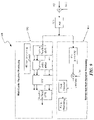
- FIG. 8 illustrates a transmitter structure of MC and DSSS overlay system.
- FIG. 9 illustrates a receiver structure of MC and DSSS overlay system.
- FIG. 10 illustrates examples of communications between a base station and multiple mobile stations transmitting DSSS and MC signals.
- FIG. 11 illustrates a mobile station sending DSSS signals to its current serving base station, or other base stations.
- FIG. 12 illustrates using interference cancellation technique to cancel interfering DSSS signal in a composite signal to obtain a clearer MC signal.
- FIG. 13 illustrates a DSSS signal and a MC signal fully overlaid or partially overlaid at MC symbol or slot boundary in time domain.
- FIG. 14 illustrates a DSSS signal with a high Peak to Average Ratio in frequency domain causing strong interference to certain MC subcarriers.
- FIG. 15 illustrates using spectrum nulls in DSSS signal to protect an MC control subchannel.
- FIG. 16 illustrates spectrum control for DSSS signal using simple sub-sampling method.
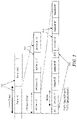
- FIG. 17 illustrates examples of communications between a base station and multiple mobile stations transmitting both DSSS and MC signals.
- FIG. 18 illustrates a typical channel response in the time and frequency domains. By estimating the peaks of a channel response in the time domain, the channel profile in the frequency domain can be obtained.
- a broadband wireless communication system where both the Multi-Carrier (MC) and direct Sequence Spread Spectrum (DSSS) signals are intentionally overlaid together in both time and frequency domains is described.
- the system takes advantage of both MC and DSSS techniques to mitigate their weaknesses.
- the MC signal is used to carry broadband data signal for its high spectral efficiency, while the DSSS signal is used for special purpose processing, such as initial random access, channel probing, and short messaging, in which signal properties such as simplicity, self synchronization, and performance under severe interference are of concern.
- both the MC and the DSSS signals are distinguishable in normal operations and the interference between the overlaid signals is insufficient to degrade the expected performance of either signal.
- the embodiments of this invention overlay the MC signal, which is transmitted without or with very low spreading, and the DSSS signal, which is transmitted at a power level lower than that of the MC signal.
- the MC signal is modulated on subcarriers in the frequency domain while the DSSS signal is modulated by the information bits or symbols in the time domain.
- the information bits modulating the DSSS sequence are always one.
- This invention further provides apparatus and means to implement the mentioned processes and methods in a broadband wireless multi-access and/or multi-cell network, using advanced techniques such as transmit power control, spreading signal design, and iterative cancellation.
- the mentioned MC system can be of any special format such as OFDM or Multi-Carrier Code Division Multiple Access (MC-CDMA).
- MC-CDMA Multi-Carrier Code Division Multiple Access
- the presented methods and apparatus can be applied to downlink, uplink, or both, where the duplexing technique can be either Time Division Duplexing (TDD) or Frequency Division Duplexing (FDD).
- TDD Time Division Duplexing
- FDD Frequency Division Duplexing
- the physical media resource (e.g., radio or cable) in a multi-carrier communication system can be divided in both the frequency and time domains. This canonical division provides a high flexibility and fine granularity for resource sharing.
- the basic structure of a multi-carrier signal in the frequency domain is made up of subcarriers. Within a particular spectral band or channel, there are a fixed number of subcarriers. There are three types of subcarriers:
- Data subcarriers which contain information data
- Pilot subcarriers whose phases and amplitudes are predetermined and made known to all receivers and which are employed for assisting system functions such as estimation of system parameters;
- Silent subcarriers which have no energy and are used for guard bands and DC carrier.
- FIG. 1 illustrates a basic structure of a multi-carrier signal in the frequency domain, made up of subcarriers.
- the data subcarriers can be arranged into groups called subchannels to support scalability and multiple-access.
- the carriers forming one subchannel are not necessarily adjacent to each other. As depicted in FIG. 1 , each user may use part or all of the subchannels.
- FIG. 2 illustrates a radio resource being divided into small units in both frequency (subchannels) and time domains (time slots).
- the basic structure of an MC signal in the time domain is made up of time slots to support multiple-access.
- FIG. 3 illustrates a frame structure of a suitable OFDM system.
- a 20 ms frame 310 is divided into four 5 ms subframes 312 .
- One subframe 312 consists of six time slots 314 and two special periods 316 , which serve transition time from downlink to uplink and vise versa.
- the six time slots in one subframe can be configured as either uplink or downlink slots symmetrically or asymmetrically.
- FIG. 4 illustrates three examples of a subframe structure in an OFDM system: one symmetric configuration 412 and two asymmetric configurations 414 , each with differing number of uplink (UL) and downlink (DL) slots.
- FIG. 5 illustrates a slot structure of an OFDM system and an overlay system.
- One 800 ⁇ s time slot 510 is comprised of 8 OFDM symbols 512 , which are overlaid by DSSS signals 514 in the time domain.
- Two guard periods GP 1 and GP 2 are allocated for the DSSS signal 514 .
- Uplink system parameters Data Rate 2, 4, 8, 16, 24 Mbps Modulation QPSK, 16-QAM Coding rate 1/8, 1/4, 1/2, 3/4 IFFT/FFT size 1024 OFDM symbol duration 100 us Guard interval 11.11 us Subcarrier spacing 9.765625 kHz System sampling rate (fs) 11.52 MHz Channel spacing 10 MHz
- FIG. 5 illustrates the overlay of the MC and DSSS signals, where the DSSS signal overlaps with the MC signal in the time domain.
- the overlaid signal can be aligned at the boundary of MC slot or MC symbol when they are synchronized (for example, DSSS signal #k in FIG. 5 ). It can also be not aligned when they are not synchronized (for example, DSSS signal #j in FIG. 5 ).
- the DSSS signal is placed at the period of cyclic prefix of the OFDM symbol.
- FIG. 6 is an illustration of MC signals overlaid with DSSS signals in the frequency domain where the power level of the DSSS signal is much lower than that of the MC signal.
- the subcarriers in a subchannel are not necessarily adjacent to each other in the frequency domain.
- FIG. 7 is similar to FIG. 6 wherein not all MC subchannels are occupied. It illustrates a scenario where some MC subchannels are not energized.
- the MC signal is modulated on subcarriers in the frequency domain while the DSSS signal is modulated in either the time domain or the frequency domain.
- the modulation symbol on the DSSS sequence is one and the sequence is unmodulated.
- FIG. 8 illustrates a transmitter structure 800 of an MC and DSSS overlay system, wherein the MC signal and DSSS signal are added together prior to Digital to Analog (D/A) conversion 830 .
- the top branch 810 is an OFDM transmitter and the bottom branch 820 is the spread spectrum transmitter.
- the S/P buffer converts the sequential inputs into parallel outputs, which are in turn inputted to the inverse discrete Fourier transform (IDFT).
- IDFT inverse discrete Fourier transform
- the outputs from the IDFT are the time domain signals, which are converted from parallel to sequential signals after a cyclic prefix is added. Adding the prefix can also be performed after the P/S conversion.
- the DSSS sequence is modulated by the information bits or symbols and the modulated signals will undergo pulse-shaping filtering so that the signal spectrum meets specified criteria.
- a digital attenuator (G 1 ) is used for the DSSS signal to adjust its transmitted signal level relative to the MC signal.
- the two signals are overlaid in the digital domain before converting to a composite analog signal.
- a second analog variable gain (G 2 ) is used subsequent to the D/A converter 830 to further control the power level of the transmitted signal.
- G 2 can be realized in multiple circuit stages.
- FIG. 9 illustrates a receiver structure 900 of an MC and DSSS overlay system.
- a composite signal is processed by a MC receiver 910 and DSSS receiver 920 .
- A/D Analog-to-Digital
- the MC receiver basically performs a reverse process of the MC transmitter.
- the MC synchronization circuit carries out the synchronization in both time and frequency for the receiver to function properly.
- the outputs of the P/S are information bits or symbols.
- the signal is despread with a matched filter or a correlator, using the access sequence, to check if the correlation peak exceeds a predefined threshold.
- the information from the DSSS receiver 920 will then be used to decode the mobile station's signature in the case of initial random access; to derive the channel information in the case of channel probing; or to decode the information bit in the case of short messaging.
- a rake receiver is used in the DSSS receiver 920 to improve its performance in a multi-path environment.
- the MC signal is processed as if no DSSS signal is present.
- advanced interference cancellation techniques can be applied to the composite signal to cancel the DSSS signal from the composite signal thus maintaining almost the same MC performance.
- the received signal can be represented by:
- M the total number of mobile station actively communicating with the current base station
- N the Gaussian noise
- I the total interference from all the mobile stations in current and other base stations.
- the system is designed such that the SINR′ MC meets the SINR requirement for the MC signal and its performance is not compromised in spite of interference from the overlaid DSSS signal.
- the DSSS signal is power controlled such that P SS is well below the noise level, N.
- SINR SS P SS /( N+I+P MC ) (5)
- SINR′ SS P SS *K SF /( N+I+P MC ) (6)
- SINR′ SS must be high enough to meet the performance requirement when detecting or decoding the information conveyed in the DSSS signal.
- K SF is chosen to be 1000, so that the DSSS signal is boosted with 30 dB spreading gain after despreading.
- FIG. 11 illustrates a mobile station 1110 sending DSSS signals to its current serving base station or other base stations. The latter case is especially helpful in hand-off processes.
- a mobile station MS k is communicating with a BS i using an MC signal while transmitting a DSSS signal to BS k .
- C 1 (in dB) is set to a proper value so that the SINR of the MC as specified in equation (4) meets its requirement.
- C 2 (in dB) is an adjustment to compensate for the power control inaccuracy.
- Open loop power control inaccuracy is mainly caused by a discrepancy between an estimated path loss by the mobile station and the actual path loss.
- C 1 is set to 9 dB for MC using QPSK modulation with 1 ⁇ 2 error control coding or 15 dB for MC using 16QAM modulation with 1 ⁇ 2 error control coding.
- C 2 is set to 10 dB or 2 dB depending on whether the mobile station is under open loop power control or closed loop power control. Power control for the DSSS signal also eases the spectrum mask requirement for the DSSS signal because the DSSS signal level is much lower than that of the MC signal.
- the spreading factor of the DSSS signal needs to be set high enough (e.g., 512 (27 dB) or higher) so that the DSSS signal can be detected in normal conditions. This requires a sufficient number of bits of the A/D converter at the base station, for example, 12 bits.
- the D/A converter at the mobile station uses 12 bits, among which 8 bits are targeted for the MC signal (assuming 3 bits are reserved for MC peak to average consideration). Thus, there are enough bits left for the DSSS signal even with significant attenuation relative to the MC signal.
- the base station employs interference cancellation techniques to cancel the DSSS interference to the MC signal.
- FIG. 12 illustrates a system for using an interference cancellation technique to cancel an interfering DSSS signal in a composite signal to obtain a clearer MC signal.
- a DSSS signal is detected by the DSSS receiver 1220 ; then it is subtracted (decision directed) from the total received signal to obtain a cleaner MC data signal in the MC receiver 1210 , as illustrated in FIG. 12 .
- multiple step iterative cancellation can be applied to further improve the effectiveness of the interference cancellation.
- the MC receiver basically performs a reverse process of the MC transmitter mentioned above.
- the MC synchronization circuit carries out the synchronization in both time and frequency for the receiver to function properly.
- the outputs of the P/S are information bits or symbols.
- DSSS sequences are chosen to have good autocorrelation and cross-correlation properties (i.e., with high peak to sidelobe ratio).
- pulse-shaping is applied to restrict the spectrum mask of DSSS signals and to reduce impacts on the MC signals in the frequency domain.
- the transmitter pulse-shaping filter applied to the DSSS signal can be a root-raised cosine (RRC) with roll-off factor ⁇ in the frequency domain.
- RRC root-raised cosine
- R ⁇ C 0 ⁇ ( t ) sin ⁇ ( ⁇ ⁇ t T C ⁇ ( 1 - ⁇ ) ) + 4 ⁇ ⁇ ⁇ t T C ⁇ cos ⁇ ( ⁇ ⁇ t T C ⁇ ( 1 + ⁇ ) ) ⁇ ⁇ t T C ⁇ ( 1 - ( 4 ⁇ ⁇ ⁇ t T C ) 2 ) ( 8 ) where T c is the chip duration.
- FIG. 13 illustrates a DSSS signal and a MC signal fully overlaid or partially overlaid with an MC symbol or slot boundary in the time domain.
- the DSSS and the MC signals may be aligned at the symbol (or slot) boundary when they are synchronized, or partially overlapped in the time domain when they are not synchronized, as shown in FIG. 13 , where a DSSS signal #m 1302 fully overlaps with a MC symbol (or slot) 1304 in time domain, while a DSSS signal #n 1306 overlaps with the MC symbol (or slot) only partially.
- FIG. 14 illustrates a DSSS signal with a high Peak to Average Ratio in the frequency domain causing strong interference to certain MC subcarriers.
- the sequence used to spread the DSSS signal has to be designed to avoid cases where the DSSS signal may have a high Peak to Average ratio (PAR) in the frequency domain and its spikes may cause severe interference with some MC subcarriers, as illustrated in FIG. 14 .
- the DSSS sequence is designed so that, in partial or in full, it has low PAR in the frequency domain using signal processing techniques, such as a PAR reduction algorithm. Either binary or non binary sequences can be used.
- Golay complementary sequences, Reed-Muller codes, or the codes designed with similar construction methods may be used to control the PAR of DSSS sequences in the frequency domain, thereby limiting the interference of DSSS signals to MC signals, which are demodulated in the frequency domain.
- guard periods are added to the DSSS signal which overlaps with one MC symbol, as shown by DSSS signal #p 1308 in FIG. 13 . The guard periods ensure that a well-designed DSSS sequence (with low PAR in frequency domain) causes little interference with the MC subcarriers even when there is time misalignment in a DSSS signal relative to the OFDM symbol period.
- control subcarriers are more important than the data subcarriers and may need to have a better protection in the overlay system.
- FIG. 15 illustrates using spectrum nulls in the DSSS signal 1502 to protect an MC control subchannel.
- the DSSS sequence is designed to have spectrum nulls at MC control subchannels to avoid excess interference with the uplink MC control signals 1504 , as illustrated in FIG. 15 .
- One such scheme is to use sub-sampling such that the chip rate of the DSSS signal is 1 ⁇ 2 or 2 ⁇ 3 of the system sampling rate, which means the DSSS spectrum will only occupy the center portion with a width of 5.76 MHz or 7.68 MHz out of the 10 MHz available spectrum 1506 , as shown in FIG. 16 . Its interference with the MC sub-carriers over the rest of the spectrum will be much lower where the MC subchannels, carrying control information or using higher modulation subcarriers (such as 16QAM), are placed.
- FIG. 10 illustrates a DSSS signal used as initial random access by the mobile station MS j 1004 , in an overlay system.
- MS 1 and MS k are transmitting MC signals to the base station BS i 1002 .
- the DSSS signal is used for initial random access and the MC signal is used by multiple mobile stations to transmit high rate data and related control information, as illustrated in FIG. 10 .
- the mobile station MS j is transmitting its initial access DSSS signal simultaneously with the MC signals from other mobile stations (in this case, MS 1 and MS K ) to the base station BS i .
- a mobile station In the initial random access of a multi-carrier multiple access system, a mobile station cannot transmit directly onto the control subchannel because its transmission time and power have not been aligned with other mobile stations.
- this mobile station When this mobile station powers up or wakes up from a sleep mode, it first listens to a base station broadcasting channel and finds an available random access DSSS channel. It then sends an initial random access signal over the DSSS channel with a certain signature code or sequence that is designated to the corresponding base station and is broadcasted to all the mobile stations by each base station.
- the initial access DSSS signal arrives at the base station together with MC signals from other mobile stations, each carrying data and control information.
- the initial power level of the DSSS signal is based on the open power loop control settings.
- a sufficient guard period is reserved in the DSSS signal to account for initial time alignment uncertainty, as shown in FIG. 5 .
- the base station If the base station successfully detects the DSSS signal, it sends the acknowledgement (ACK) carrying information such as a signature or other unique mobile station identifier and power and time adjustments of the mobile on the downlink control channel in the next available timeslot.
- ACK acknowledgement
- the mobile station whose transmission signature matches that of the acknowledgement then moves to the designated uplink MC control channel using the assigned time and power values and further completes the message transmission.
- the mobile station If no feedback is received at the mobile station after a pre-defined number of slots, it assumes that the access slot was not detected by the base station, and will ramp up the transmission power of the DSSS signal by one step and re-transmit it, until it reaches the maximum allowable transmit signal power or the maximum retry times.
- the power ramping step of the mobile station is set to be 1 dB or 2 dB which is configured by the base station on the downlink broadcasting channel.
- the maximum allowable transmit signal power and the retry times are also controlled by the base station depending on the uplink modulation/coding scheme and available access channels.
- the DSSS signal can also be used for channel probing and short messaging.
- the DSSS signal is used to assist estimation of channel characteristics.
- the mobile station is already synchronized in time and frequency with the base station, and its transmission of the MC signal is under closed-loop power control with the base station.
- FIG. 17 illustrates examples of communications between a base station 1702 and multiple mobile stations 1704 transmitting both DSSS and MC signals.
- DSSS signal is used for channel probing or to carry short messages.
- MS j 1704 is transmitting both an MC signal and a DSSS signal to the base station BS i 1702 . It is also under closed loop power control with the base station BS i 1702 .
- the mobile station MS j 1704 is transmitting its DSSS signal simultaneously with its own MC signal.
- Other mobile stations in this case, MS 1 1704 and MS K 1704 ) are transmitting either MC or DSSS signals to the base station BS i 1702 .
- FIG. 18 illustrates a typical channel response in the time domain 1802 and the frequency domain 1804 .
- the channel profile in the frequency domain 1804 can be obtained.
- a typical channel response in the time domain and frequency domain for a broadband wireless system is shown in FIG. 18 .
- the peaks of a channel response in time can be detected.
- the initial power settings will be much more accurate than by using open loop power control alone.
- the margin reserved for power control inaccuracy can be reduced to a much smaller value.
- a bigger spreading factor can be used since no data information needs to be conveyed in the DSSS signal. This leaves a dynamic range large enough for detecting multi-path peaks from the output of the match filter or correlator, thereby generating a better channel profile.
- the base station dictates the mobile station to transmit the channel probing DSSS when it needs an update of the mobile station's channel characteristics.
- the base station polls the mobile station during its silent period and gets an update of the mobile station's information such as transmission timing and power from the probing DSSS signal.
- the channel profile information is used by the base station to determine the proper modulation/coding and pilot pattern.
- the channel profile information is used for advanced antenna techniques such as beamforming.
- channel probing with the DSSS signaling is performed without close loop power control or time synchronization.
- the DSSS signal is used to carry short messages.
- the mobile station is already synchronized in time and frequency with the base station, and its transmission of a MC signal is also under closed-loop power control with the base station.
- the mobile station MS j is transmitting its DSSS signal carrying a short message simultaneously with its own MC signal.
- Other mobile stations in this case, MS 1 and MS K ) are transmitting either the MC signal or DSSS signal to the base station BS i .
- the short message carried by the DSSS signal has a much lower data rate compared with that of the MC signal.
- short messaging using the DSSS signaling is performed without close loop power control or time synchronization.
Landscapes
- Engineering & Computer Science (AREA)
- Signal Processing (AREA)
- Computer Networks & Wireless Communication (AREA)
- Physics & Mathematics (AREA)
- Spectroscopy & Molecular Physics (AREA)
- Power Engineering (AREA)
- Mobile Radio Communication Systems (AREA)
Abstract
Description
| TABLE 1 |
| Uplink system |
| Data Rate |
| 2, 4, 8, 16, 24 Mbps | ||
| Modulation | QPSK, 16- | |
| Coding rate | ||
| 1/8, 1/4, 1/2, 3/4 | ||
| IFFT/FFT size | 1024 |
| OFDM symbol duration | 100 | us | ||
| Guard interval | 11.11 | us | ||
| Subcarrier spacing | 9.765625 | kHz | ||
| System sampling rate (fs) | 11.52 | MHz | ||
| Channel spacing | 10 | MHz | ||
s i(t)=G i,2*[G i,1 *s i,SS(t)+b i *s i,MC(t)] (1)
where bi is 0 when there is no MC signal and is 1 when an MC signal is present. Similarly, Gi,1 is 0 when there is no DSSS signal and varies depending on the power setting of the DSSS signal relative to the MC signal when a DSSS signal is present. Gi,2 is used to control the total transmission power for user i. The received signal can be represented by:
where M is the total number of mobile station actively communicating with the current base station, N is the Gaussian noise, and I is the total interference from all the mobile stations in current and other base stations.
SINRMC =P MC/(N+I) (3)
when the DSSS signal is not present; and is
SINR′MC =P MC/(N+I+P SS) (4)
when the DSSS signal is present. The system is designed such that the SINR′MC meets the SINR requirement for the MC signal and its performance is not compromised in spite of interference from the overlaid DSSS signal.
SINRSS =P SS/(N+I+P MC) (5)
SINR′SS =P SS *K SF/(N+I+P MC) (6)
T MS_tx =P BS_rx_des +L path −C 1 −C 2 (7)
where Tc is the chip duration.
Claims (100)
Priority Applications (3)
| Application Number | Priority Date | Filing Date | Title |
|---|---|---|---|
| US17/092,786 US11368347B2 (en) | 2004-01-29 | 2020-11-09 | Channel probing signal for a broadband communication system |
| US17/845,702 US11804870B2 (en) | 2004-01-29 | 2022-06-21 | Channel probing signal for a broadband communication system |
| US18/229,787 US20230378997A1 (en) | 2004-01-29 | 2023-08-03 | Channel probing signal for a broadband communication system |
Applications Claiming Priority (12)
| Application Number | Priority Date | Filing Date | Title |
|---|---|---|---|
| US54003204P | 2004-01-29 | 2004-01-29 | |
| US54058604P | 2004-01-30 | 2004-01-30 | |
| PCT/US2005/003518 WO2005074166A1 (en) | 2004-01-29 | 2005-01-27 | Methods and apparatus for overlaying multi-carrier and direct sequence spread spectrum signals in a broadband wireless communication system |
| US10/583,229 US7864725B2 (en) | 2004-01-29 | 2005-01-27 | Methods and apparatus for overlaying multi-carrier and direct sequence spread spectrum signals in a broadband wireless communication system |
| US12/975,226 US8094611B2 (en) | 2004-01-29 | 2010-12-21 | Methods and apparatus for signal transmission and reception in a broadband communication system |
| US13/347,644 US8428009B2 (en) | 2004-01-29 | 2012-01-10 | Methods and apparatus for signal transmission and reception in a broadband communication system |
| US13/861,942 US8767522B2 (en) | 2004-01-29 | 2013-04-12 | Methods and apparatus for signal transmission and reception in a broadband communication system |
| US14/321,615 US9948488B2 (en) | 2004-01-29 | 2014-07-01 | Channel probing signal for a broadband communication system |
| US15/953,950 US10771302B2 (en) | 2004-01-29 | 2018-04-16 | Channel probing signal for a broadband communication system |
| US16/902,740 US10833908B2 (en) | 2004-01-29 | 2020-06-16 | Channel probing signal for a broadband communication system |
| US16/908,067 US10826740B2 (en) | 2004-01-29 | 2020-06-22 | Channel probing signal for a broadband communication system |
| US17/092,786 US11368347B2 (en) | 2004-01-29 | 2020-11-09 | Channel probing signal for a broadband communication system |
Related Parent Applications (2)
| Application Number | Title | Priority Date | Filing Date |
|---|---|---|---|
| US16/902,740 Continuation US10833908B2 (en) | 2004-01-29 | 2020-06-16 | Channel probing signal for a broadband communication system |
| US16/908,067 Continuation US10826740B2 (en) | 2004-01-29 | 2020-06-22 | Channel probing signal for a broadband communication system |
Related Child Applications (1)
| Application Number | Title | Priority Date | Filing Date |
|---|---|---|---|
| US17/845,702 Continuation US11804870B2 (en) | 2004-01-29 | 2022-06-21 | Channel probing signal for a broadband communication system |
Publications (2)
| Publication Number | Publication Date |
|---|---|
| US20210058281A1 US20210058281A1 (en) | 2021-02-25 |
| US11368347B2 true US11368347B2 (en) | 2022-06-21 |
Family
ID=34830499
Family Applications (11)
| Application Number | Title | Priority Date | Filing Date |
|---|---|---|---|
| US10/583,229 Active 2026-07-03 US7864725B2 (en) | 2004-01-29 | 2005-01-27 | Methods and apparatus for overlaying multi-carrier and direct sequence spread spectrum signals in a broadband wireless communication system |
| US12/975,226 Expired - Lifetime US8094611B2 (en) | 2004-01-29 | 2010-12-21 | Methods and apparatus for signal transmission and reception in a broadband communication system |
| US13/347,644 Expired - Lifetime US8428009B2 (en) | 2004-01-29 | 2012-01-10 | Methods and apparatus for signal transmission and reception in a broadband communication system |
| US13/861,942 Expired - Lifetime US8767522B2 (en) | 2004-01-29 | 2013-04-12 | Methods and apparatus for signal transmission and reception in a broadband communication system |
| US14/321,615 Expired - Lifetime US9948488B2 (en) | 2004-01-29 | 2014-07-01 | Channel probing signal for a broadband communication system |
| US15/953,950 Expired - Lifetime US10771302B2 (en) | 2004-01-29 | 2018-04-16 | Channel probing signal for a broadband communication system |
| US16/902,740 Expired - Lifetime US10833908B2 (en) | 2004-01-29 | 2020-06-16 | Channel probing signal for a broadband communication system |
| US16/908,067 Expired - Lifetime US10826740B2 (en) | 2004-01-29 | 2020-06-22 | Channel probing signal for a broadband communication system |
| US17/092,786 Expired - Lifetime US11368347B2 (en) | 2004-01-29 | 2020-11-09 | Channel probing signal for a broadband communication system |
| US17/845,702 Expired - Lifetime US11804870B2 (en) | 2004-01-29 | 2022-06-21 | Channel probing signal for a broadband communication system |
| US18/229,787 Abandoned US20230378997A1 (en) | 2004-01-29 | 2023-08-03 | Channel probing signal for a broadband communication system |
Family Applications Before (8)
| Application Number | Title | Priority Date | Filing Date |
|---|---|---|---|
| US10/583,229 Active 2026-07-03 US7864725B2 (en) | 2004-01-29 | 2005-01-27 | Methods and apparatus for overlaying multi-carrier and direct sequence spread spectrum signals in a broadband wireless communication system |
| US12/975,226 Expired - Lifetime US8094611B2 (en) | 2004-01-29 | 2010-12-21 | Methods and apparatus for signal transmission and reception in a broadband communication system |
| US13/347,644 Expired - Lifetime US8428009B2 (en) | 2004-01-29 | 2012-01-10 | Methods and apparatus for signal transmission and reception in a broadband communication system |
| US13/861,942 Expired - Lifetime US8767522B2 (en) | 2004-01-29 | 2013-04-12 | Methods and apparatus for signal transmission and reception in a broadband communication system |
| US14/321,615 Expired - Lifetime US9948488B2 (en) | 2004-01-29 | 2014-07-01 | Channel probing signal for a broadband communication system |
| US15/953,950 Expired - Lifetime US10771302B2 (en) | 2004-01-29 | 2018-04-16 | Channel probing signal for a broadband communication system |
| US16/902,740 Expired - Lifetime US10833908B2 (en) | 2004-01-29 | 2020-06-16 | Channel probing signal for a broadband communication system |
| US16/908,067 Expired - Lifetime US10826740B2 (en) | 2004-01-29 | 2020-06-22 | Channel probing signal for a broadband communication system |
Family Applications After (2)
| Application Number | Title | Priority Date | Filing Date |
|---|---|---|---|
| US17/845,702 Expired - Lifetime US11804870B2 (en) | 2004-01-29 | 2022-06-21 | Channel probing signal for a broadband communication system |
| US18/229,787 Abandoned US20230378997A1 (en) | 2004-01-29 | 2023-08-03 | Channel probing signal for a broadband communication system |
Country Status (6)
| Country | Link |
|---|---|
| US (11) | US7864725B2 (en) |
| EP (1) | EP1712019B1 (en) |
| KR (1) | KR100818774B1 (en) |
| CN (1) | CN102064848B (en) |
| ES (1) | ES2885101T3 (en) |
| WO (1) | WO2005074166A1 (en) |
Cited By (1)
| Publication number | Priority date | Publication date | Assignee | Title |
|---|---|---|---|---|
| US20240389158A1 (en) * | 2021-09-30 | 2024-11-21 | Amit Kalhan | Group random access |
Families Citing this family (54)
| Publication number | Priority date | Publication date | Assignee | Title |
|---|---|---|---|---|
| WO2005074166A1 (en) | 2004-01-29 | 2005-08-11 | Neocific, Inc. | Methods and apparatus for overlaying multi-carrier and direct sequence spread spectrum signals in a broadband wireless communication system |
| CN1879426B (en) | 2004-01-29 | 2010-06-23 | 桥扬科技有限公司 | Method and apparatus for multi-carrier, multi-cell wireless communication networks |
| WO2005081439A1 (en) | 2004-02-13 | 2005-09-01 | Neocific, Inc. | Methods and apparatus for multi-carrier communication systems with adaptive transmission and feedback |
| KR100635011B1 (en) * | 2004-11-16 | 2006-10-16 | 한국전자통신연구원 | Transmitter of orthogonal frequency division multiple access system capable of adjusting gain according to the number of subchannels and data transmission method |
| US7715460B2 (en) | 2005-04-22 | 2010-05-11 | Interdigital Technology Corporation | Hybrid orthogonal frequency division multiple access system and method |
| US8145262B2 (en) | 2005-05-17 | 2012-03-27 | Pine Valley Investments, Inc. | Multimode land mobile radio |
| US8279868B2 (en) | 2005-05-17 | 2012-10-02 | Pine Valley Investments, Inc. | System providing land mobile radio content using a cellular data network |
| KR100810280B1 (en) * | 2005-05-27 | 2008-03-06 | 삼성전자주식회사 | Method and system for transmitting and receiving data in frequency overlay communication system |
| US7894818B2 (en) * | 2005-06-15 | 2011-02-22 | Samsung Electronics Co., Ltd. | Apparatus and method for multiplexing broadcast and unicast traffic in a multi-carrier wireless network |
| WO2007031568A1 (en) * | 2005-09-14 | 2007-03-22 | Universite De Rennes 1 | Method for transmitting a multicarrier spectrum-spread signal, reception method, corresponding transmitting, receiving device and signal |
| US8693430B2 (en) | 2005-09-28 | 2014-04-08 | Neocific, Inc. | Method and system for multi-carrier packet communication with reduced overhead |
| WO2007038750A1 (en) * | 2005-09-28 | 2007-04-05 | Neocific, Inc. | Method and system for multi-carrier packet communication with reduced overhead |
| US8194682B2 (en) * | 2006-08-07 | 2012-06-05 | Pine Valley Investments, Inc. | Multiple protocol land mobile radio system |
| KR100810351B1 (en) * | 2006-11-15 | 2008-03-04 | 재단법인서울대학교산학협력재단 | Channel Probing System and Method in Communication System |
| KR101390110B1 (en) * | 2007-02-22 | 2014-04-28 | 삼성전자주식회사 | Apparatus and method for transmitting and receiving a signal in a communication system |
| US8942150B2 (en) * | 2007-03-19 | 2015-01-27 | Qualcomm Incorporated | Uplink timing control |
| WO2009069177A1 (en) * | 2007-11-28 | 2009-06-04 | Fujitsu Limited | Radio transmitting apparatus, radio receiving apparatus, radio transmitting/receiving system, and methods therefor |
| KR100904533B1 (en) * | 2008-01-11 | 2009-06-25 | 엘지전자 주식회사 | Transmission timing adjustment method, continuous packet transmission method and mobile communication terminal |
| EP2248314A1 (en) * | 2008-02-25 | 2010-11-10 | Nxp B.V. | Arrangement and approach for time slot index synchronization for wireless communications |
| US8406168B2 (en) | 2009-03-13 | 2013-03-26 | Harris Corporation | Asymmetric broadband data radio network |
| US8693305B2 (en) * | 2009-08-24 | 2014-04-08 | Qualcomm Incorporated | Method and apparatus for detecting OFDM signals in the presence of frequency orthogonal OFDM interferers |
| US8665063B2 (en) * | 2009-09-25 | 2014-03-04 | Northwestern University | Neighbor discovery techniques |
| US9832769B2 (en) | 2009-09-25 | 2017-11-28 | Northwestern University | Virtual full duplex network communications |
| US8718101B2 (en) * | 2009-12-29 | 2014-05-06 | Acer Incorporated | Pilot selection method, wireless communication system and base station thereof |
| US20120008555A1 (en) * | 2010-06-23 | 2012-01-12 | Qualcomm Incorporated | Transmit and receive processing in the presence of interference in a wireless network |
| WO2012108616A1 (en) * | 2011-02-13 | 2012-08-16 | Lg Electronics Inc. | Method for transmitting uplink control information and user equipment, and method for receiving uplink control information and base station |
| GB2489922A (en) * | 2011-04-06 | 2012-10-17 | Univ Bangor | Synchronising optical OFDM signal with pattern of DC offset levels superimposed upon OFDM symbols |
| EP2547165B1 (en) * | 2011-07-13 | 2017-02-01 | HTC Corporation | Method of handling random access procedure with deactivation timer |
| CN102307174B (en) * | 2011-09-09 | 2013-04-24 | 北京交通大学 | Low density trap wave point setting method |
| US8995560B2 (en) * | 2011-10-26 | 2015-03-31 | Google Technology Holdings LLC | Power detection of individual carriers of a multiple-carrier wideband signal |
| US8731027B2 (en) * | 2011-12-05 | 2014-05-20 | Battelle Energy Alliance, Llc | Methods and apparatuses using filter banks for multi-carrier spread-spectrum signals |
| US8565181B2 (en) * | 2012-02-06 | 2013-10-22 | Neocific, Inc. | Methods and apparatus for multi-carrier communications with efficient control signaling |
| US9112634B2 (en) * | 2012-02-10 | 2015-08-18 | Qualcomm Incorporated | Reducing network acquisition time |
| EP2814288B1 (en) * | 2012-02-10 | 2017-09-27 | Lg Electronics Inc. | Method and apparatus for accessing channel in wlan system |
| US9832286B2 (en) | 2013-03-14 | 2017-11-28 | Angelo Marino TUZI | Asynchronous ubiquitous protocol |
| WO2014172849A1 (en) * | 2013-04-24 | 2014-10-30 | 华为技术有限公司 | Transmitter and signal transmission method |
| KR101473592B1 (en) * | 2013-12-05 | 2014-12-16 | 한국항공우주연구원 | Apparatus and method for distortion signal detection |
| US10693602B2 (en) * | 2015-05-29 | 2020-06-23 | Futurewei Technologies, Inc. | System and method for a long-term evolution (LTE)-compatible subframe structure for wideband LTE |
| US10656244B2 (en) * | 2016-04-08 | 2020-05-19 | General Radar Corp. | Reconfigurable correlator (pulse compression receiver) and beam former based on multi-gigabit serial transceivers (SERDES) |
| US10887143B2 (en) * | 2016-05-06 | 2021-01-05 | Samsung Electronics Co., Ltd. | Method and apparatus for initial access in wireless communication systems |
| WO2018028838A1 (en) | 2016-08-12 | 2018-02-15 | Telefonaktiebolaget Lm Ericsson (Publ) | Technique for determining a channel width of a channel used in a wireless communication network |
| DE102017219685B3 (en) * | 2017-11-06 | 2019-05-09 | Laird Dabendorf Gmbh | Method and apparatus for amplifying radio signals between a terminal and an antenna in a first frequency band and in a second frequency band |
| US10924164B2 (en) | 2018-05-29 | 2021-02-16 | Skyworks Solutions, Inc. | Beamforming communication systems with power control based on antenna pattern configuration |
| US10581481B1 (en) | 2018-09-18 | 2020-03-03 | Battelle Energy Alliance, Llc | Communication device, spread-spectrum receiver, and related method using normalized matched filter for improving signal-to-noise ratio in harsh environments |
| CN112673678B (en) * | 2018-09-28 | 2024-01-23 | 株式会社Ntt都科摩 | Method and equipment for uplink power control |
| CN109361497A (en) * | 2018-10-11 | 2019-02-19 | 天津大学 | A pilot design method for OFDM cognitive radio system |
| CN111757448B (en) * | 2019-03-29 | 2021-09-07 | 华为技术有限公司 | A power control method and device |
| US12003350B1 (en) | 2020-02-29 | 2024-06-04 | Space Exploration Technologies Corp. | Configurable orthogonal frequency division multiplexing (OFDM) signal and transmitter and receiver for user terminal to satellite uplink communications |
| US12126374B2 (en) | 2020-03-06 | 2024-10-22 | Battelle Energy Alliance, Llc | Spread spectrum communication, and associated devices, systems, and methods |
| US11122525B1 (en) * | 2020-06-24 | 2021-09-14 | Charter Communications Operating, Llc | Wireless channel access and power adjust access requests |
| KR20220076108A (en) | 2020-11-30 | 2022-06-08 | 삼성전자주식회사 | Low complexity widely linear reception processing in multi-antenna wireless communication system and method thereof |
| CN112688755B (en) * | 2020-12-22 | 2022-06-03 | 重庆邮电大学 | Method and device for generating length 3N four-phase aperiodic complementary sequence pair signal |
| KR20220102347A (en) | 2021-01-13 | 2022-07-20 | 삼성전자주식회사 | Electronic device for controlling spread spectrum clock generator and operating method thereof |
| US12308947B2 (en) | 2022-09-13 | 2025-05-20 | Qualcomm Incorporated | Concurrent code division and frequency division signaling via an uplink channel |
Citations (88)
| Publication number | Priority date | Publication date | Assignee | Title |
|---|---|---|---|---|
| JPH09233047A (en) | 1996-02-22 | 1997-09-05 | Sharp Corp | Orthogonal frequency division multiplex signal transmission system |
| JPH10210002A (en) | 1997-01-17 | 1998-08-07 | Victor Co Of Japan Ltd | Mobile communication system |
| US5825807A (en) | 1995-11-06 | 1998-10-20 | Kumar; Derek D. | System and method for multiplexing a spread spectrum communication system |
| US5828650A (en) | 1995-07-03 | 1998-10-27 | Nokia Mobile Phones Ltd. | Combined modulation--and multiple access method for radio signals |
| US5867478A (en) | 1997-06-20 | 1999-02-02 | Motorola, Inc. | Synchronous coherent orthogonal frequency division multiplexing system, method, software and device |
| US5898338A (en) | 1996-09-20 | 1999-04-27 | Spectrian | Adaptive digital predistortion linearization and feed-forward correction of RF power amplifier |
| US5909436A (en) | 1995-08-28 | 1999-06-01 | Telia Ab | Random access orthogonal frequency division multiplex system and method |
| US5929704A (en) | 1998-02-20 | 1999-07-27 | Spectrian | Control of RF error extraction using auto-calibrating RF correlator |
| WO2000035121A1 (en) | 1998-12-08 | 2000-06-15 | Nokia Networks Oy | A method for call setup in a radio telecommunication network using macro diversity |
| US6078216A (en) | 1998-03-31 | 2000-06-20 | Spectrian Corporation | Aliased wide band performance monitor for adjusting predistortion and vector modulator control parameters of RF amplifier |
| US6101179A (en) | 1997-09-19 | 2000-08-08 | Qualcomm Incorporated | Accurate open loop power control in a code division multiple access communication system |
| US6141546A (en) | 1996-10-18 | 2000-10-31 | Motorola, Inc. | Mobile telephone systems |
| US6175550B1 (en) | 1997-04-01 | 2001-01-16 | Lucent Technologies, Inc. | Orthogonal frequency division multiplexing system with dynamically scalable operating parameters and method thereof |
| US6188717B1 (en) * | 1996-11-19 | 2001-02-13 | Deutsche Forschungsanstalt Fur Luft-Und Raumfahrt E.V. | Method of simultaneous radio transmission of digital data between a plurality of subscriber stations and a base station |
| WO2001061880A1 (en) | 2000-02-19 | 2001-08-23 | Nec Corporation | Method for frequency offset estimation in a direct sequence spread spectrum communications receiver |
| KR20010083789A (en) | 2001-06-26 | 2001-09-03 | 유흥균 | Design Method of Sinc-Function Chip Waveform for Capacity Increase and Signal Quality Improvement in CDMA System |
| US20010021182A1 (en) | 2000-02-29 | 2001-09-13 | Kabushiki Kaisha Toshiba | Transmitter apparatus and receiver apparatus and base station making use of orthogonal frequency division multiplexing and spectrum spreading |
| US6434364B1 (en) | 1998-12-24 | 2002-08-13 | Telefonaktiebolaget Lm Ericsson (Publ) | Wireless communication system that supports mobile test software agents |
| US20020141483A1 (en) | 1999-07-28 | 2002-10-03 | Markus Doetsch | Method for estimating channel impulse responses of a mobile radio channel |
| US20020159422A1 (en) | 2001-03-09 | 2002-10-31 | Xiaodong Li | Communication system using OFDM for one direction and DSSS for another direction |
| US6480558B1 (en) | 1999-03-17 | 2002-11-12 | Ericsson Inc. | Synchronization and cell search methods and apparatus for wireless communications |
| US6515960B1 (en) | 1997-08-27 | 2003-02-04 | Sony Corporation | Radio communication system |
| CN1407745A (en) | 2001-08-29 | 2003-04-02 | 西安电子科技大学 | Orthogonal frequency division multiplex transmission system for digital surface broadcasting |
| US20030072255A1 (en) | 2001-10-17 | 2003-04-17 | Jianglei Ma | System access and synchronization methods for MIMO OFDM communications systems and physical layer packet and preamble design |
| US20030081538A1 (en) | 2001-10-18 | 2003-05-01 | Walton Jay R. | Multiple-access hybrid OFDM-CDMA system |
| US6567383B1 (en) | 1998-02-18 | 2003-05-20 | Sony International (Europe) Gmbh | Header structure for TDD systems |
| KR20030060892A (en) | 2000-09-14 | 2003-07-16 | 프랑스 텔레콤 | Method for optimal estimation of a propagation channel relying solely on pilot symbols and corresponding estimator |
| WO2003058881A2 (en) | 2002-01-09 | 2003-07-17 | Koninklijke Philips Electronics N.V. | Coexistence of modulation schemes in a wlan |
| US6600772B1 (en) | 2000-03-21 | 2003-07-29 | Interdigital Communications Corporation | Combined closed loop/open loop power control in a time division duplex communication system |
| US20030179776A1 (en) | 2001-06-29 | 2003-09-25 | Atsushi Sumasu | Multicarrier transmitter, multicarrier receiver, and multicarrier wireless communication method |
| CN1445949A (en) | 2002-03-18 | 2003-10-01 | 电子科技大学 | New communication method of combined spread spectrum |
| CN1452326A (en) | 2002-04-15 | 2003-10-29 | 华为技术有限公司 | Method for switching-on and synchronization of mobile terminal of radio local network system |
| US6643281B1 (en) | 1998-03-05 | 2003-11-04 | At&T Wireless Services, Inc. | Synchronization preamble method for OFDM waveforms in a communications system |
| US20040001429A1 (en) | 2002-06-27 | 2004-01-01 | Jianglei Ma | Dual-mode shared OFDM methods/transmitters, receivers and systems |
| US20040082356A1 (en) | 2002-10-25 | 2004-04-29 | Walton J. Rodney | MIMO WLAN system |
| US6731673B1 (en) | 1999-02-19 | 2004-05-04 | Nortel Networks Limited | Synchronization channel with cyclic hierarchical sequences and method for cell site search with low detector complexity |
| US20040085946A1 (en) | 2001-12-07 | 2004-05-06 | Minori Morita | Multi-carrier transmission/reception apparatus |
| US6741578B1 (en) | 1999-04-29 | 2004-05-25 | Samsung Electronics Co., Ltd. | Apparatus and method for synchronizing channels in a W-CDMA communication system |
| US20040109432A1 (en) | 2002-08-26 | 2004-06-10 | Rajiv Laroia | Beacon signaling in a wireless system |
| US20040114504A1 (en) | 2002-10-23 | 2004-06-17 | Samsung Electronics Co., Ltd. | Apparatus and method for generating a preamble sequence in an OFDM communication system |
| US6771706B2 (en) | 2001-03-23 | 2004-08-03 | Qualcomm Incorporated | Method and apparatus for utilizing channel state information in a wireless communication system |
| US20040160921A1 (en) | 2001-04-26 | 2004-08-19 | Yrjo Kaipainen | Data transmission method and equipment |
| US20040171357A1 (en) | 2001-07-02 | 2004-09-02 | Andreas Lobinger | Method for operating a mobile radio communications system and stations thereof |
| US20040190598A1 (en) | 2001-08-30 | 2004-09-30 | Hiroyuki Seki | Multicarrier CDMA transmission system and transmission method |
| US20040228267A1 (en) | 2003-05-12 | 2004-11-18 | Avneesh Agrawal | Fast frequency hopping with a code division multiplexed pilot in an OFDMA system |
| US20040264600A1 (en) | 2003-06-30 | 2004-12-30 | Ping-Chieh Kao | Radio Receiver Supporting Multiple Modulation Formats with a Single Pair of ADCs |
| US6839876B1 (en) | 1999-07-06 | 2005-01-04 | Nortel Networks Limited | Preamble using Golay sequence for access channel in cellular communications systems |
| US6847678B2 (en) | 2002-04-25 | 2005-01-25 | Raytheon Company | Adaptive air interface waveform |
| US6882619B1 (en) * | 2001-02-21 | 2005-04-19 | At&T Corp. | Interference suppressing OFDM method for wireless communications |
| US20050111397A1 (en) | 2002-12-06 | 2005-05-26 | Attar Rashid A. | Hybrid TDM/OFDM/CDM reverse link transmission |
| US6922388B1 (en) | 2000-02-11 | 2005-07-26 | Lucent Technologies Inc. | Signal construction, detection and estimation for uplink timing synchronization and access control in a multi-access wireless communication system |
| US7035663B1 (en) | 2001-10-30 | 2006-04-25 | Sprint Communications Company, L.P. | Wireless telecommunications overlay system |
| EP1650891A1 (en) | 2003-07-29 | 2006-04-26 | Fujitsu Limited | Pilot multiplexing method and transmission/reception device in ofdm system |
| US7039001B2 (en) | 2002-10-29 | 2006-05-02 | Qualcomm, Incorporated | Channel estimation for OFDM communication systems |
| US7062002B1 (en) | 1999-04-29 | 2006-06-13 | Siemens Aktiengesellschaft | Method for synchronizing a base station with a mobile station, a base station and a mobile station |
| US7123934B1 (en) | 2002-02-15 | 2006-10-17 | Sprint Communications Company L.P. | Telecommunications overlay system |
| US20060245409A1 (en) | 1999-07-09 | 2006-11-02 | Sari Korpela | Method for transmitting a sequence of symbols |
| US7133352B1 (en) * | 1999-09-20 | 2006-11-07 | Zion Hadad | Bi-directional communication channel |
| US7149239B2 (en) | 2001-04-03 | 2006-12-12 | Nortel Networks Limited | Communication system and methods of estimating channel impulse responses therein |
| US7161987B2 (en) | 2001-09-26 | 2007-01-09 | Conexant, Inc. | Single-carrier to multi-carrier wireless architecture |
| US7161985B2 (en) | 2000-12-20 | 2007-01-09 | Siemens Aktiengesellschaft | Method and device for transmitting data on at least one electrical power supply line |
| US7218666B2 (en) | 2000-12-29 | 2007-05-15 | Motorola, Inc. | Method and system for transmission and frequency domain equalization for wideband CDMA system |
| US7260054B2 (en) | 2002-05-30 | 2007-08-21 | Denso Corporation | SINR measurement method for OFDM communications systems |
| US7263058B2 (en) | 2001-08-27 | 2007-08-28 | Samsung Electronics Co., Ltd. | Apparatus and method for generating preamble sequence in a BWA communication system using OFDM |
| US7274652B1 (en) | 2000-06-02 | 2007-09-25 | Conexant, Inc. | Dual packet configuration for wireless communications |
| US7317931B2 (en) | 2000-05-19 | 2008-01-08 | Fujitsu Limited | Transmission rate changes in communications networks |
| US7324434B2 (en) * | 2001-08-30 | 2008-01-29 | Ntt Docomo, Inc. | Radio transmission system and method, and transmitter apparatus and receiver apparatus used in the radio transmission system |
| US7342974B2 (en) | 2003-03-20 | 2008-03-11 | Silicon Integrated Systems Corp. | Channel estimation in OFDM systems |
| US7411897B2 (en) | 2002-11-20 | 2008-08-12 | Samsung Electronics Co., Ltd | Method and apparatus for generating an edge sidelobe canceling signal and uplink communication method and apparatus using the same in an OFDMA system |
| US7418042B2 (en) | 2003-09-17 | 2008-08-26 | Atheros Communications, Inc. | Repetition coding for a wireless system |
| US7420915B2 (en) * | 2001-08-27 | 2008-09-02 | Matsushita Electric Industrial Co. ,Ltd. | Radio communications apparatus and radio communications method |
| US7443829B2 (en) | 2004-09-09 | 2008-10-28 | Toshiba Corporation | Uplink interference cancellation |
| US20080304551A1 (en) | 2004-01-29 | 2008-12-11 | Neocific, Inc. | Methods and Apparatus for Overlaying Multi-Carrier and Direct Sequence Spread Spectrum Signals in a Broadband Wireless Communication System |
| US7555268B2 (en) | 2003-12-19 | 2009-06-30 | Broadcom Corporation | RF transmitter having multiple constant transmit power levels |
| US7567624B1 (en) | 1999-07-30 | 2009-07-28 | Texas Instruments Incorporated | System and method of communicating using combined signal parameter diversity |
| US7639660B2 (en) * | 2003-12-17 | 2009-12-29 | Electronics And Telecommunications Research Institute | Apparatus for OFDMA transmission and reception for coherent detection in uplink of wireless communication system and method thereof |
| US7646747B2 (en) | 2000-01-24 | 2010-01-12 | Ntt Docomo, Inc. | Channel constructing method and base station using the method |
| US7650152B2 (en) | 2000-12-15 | 2010-01-19 | Adaptix, Inc. | Multi-carrier communications with adaptive cluster configuration and switching |
| US7693032B2 (en) | 2004-02-13 | 2010-04-06 | Neocific, Inc. | Methods and apparatus for multi-carrier communication systems with adaptive transmission and feedback |
| US7738437B2 (en) | 2003-01-21 | 2010-06-15 | Nortel Networks Limited | Physical layer structures and initial access schemes in an unsynchronized communication network |
| US7873009B2 (en) | 2003-12-22 | 2011-01-18 | Telefonaktiebolaget L M Ericsson (Publ) | Method and system of radio communications of traffic with different characteristics |
| US7876716B2 (en) * | 2001-04-19 | 2011-01-25 | Panasonic Corporation | Base station apparatus and radio communication method |
| US7907592B2 (en) | 2007-07-06 | 2011-03-15 | Lg Electronics Inc. | Method of performing cell search in wireless communication system |
| US8009660B2 (en) | 2004-01-29 | 2011-08-30 | Neocific, Inc. | Methods and apparatus using cell-specific and common pilot subcarriers in multi-carrier, multi-cell wireless communication networks |
| US8089887B2 (en) | 2002-11-19 | 2012-01-03 | Massachusetts Institute Of Technology | Method for automatic signal routing in ad hoc networks |
| US8199632B2 (en) | 1995-02-06 | 2012-06-12 | Htc Corporation | Systems and method for orthogonal frequency divisional multiplexing |
| US8467366B2 (en) | 2004-03-09 | 2013-06-18 | Neocific, Inc. | Methods and apparatus for random access in multi-carrier communication systems |
| US10638468B2 (en) | 2001-02-23 | 2020-04-28 | Ipr Licensing, Inc. | Qualifying available reverse link coding rates from access channel power setting |
Family Cites Families (140)
| Publication number | Priority date | Publication date | Assignee | Title |
|---|---|---|---|---|
| US3488445A (en) | 1966-11-14 | 1970-01-06 | Bell Telephone Labor Inc | Orthogonal frequency multiplex data transmission system |
| US5519730A (en) | 1990-06-12 | 1996-05-21 | Jasper; Steven C. | Communication signal having a time domain pilot component |
| EP0565507A3 (en) | 1992-04-10 | 1994-11-30 | Ericsson Ge Mobile Communicat | Power control for random access call set-up in a mobile telephone system |
| US5471647A (en) | 1993-04-14 | 1995-11-28 | The Leland Stanford Junior University | Method for minimizing cross-talk in adaptive transmission antennas |
| EP0639035B1 (en) | 1993-08-12 | 2002-10-23 | Nortel Networks Limited | Base station antenna arrangement |
| JP3289610B2 (en) | 1996-07-31 | 2002-06-10 | 日本ビクター株式会社 | OFDM demodulator and method |
| US6192068B1 (en) | 1996-10-03 | 2001-02-20 | Wi-Lan Inc. | Multicode spread spectrum communications system |
| US5933421A (en) | 1997-02-06 | 1999-08-03 | At&T Wireless Services Inc. | Method for frequency division duplex communications |
| WO1998037638A2 (en) | 1997-02-24 | 1998-08-27 | At & T Wireless Services, Inc. | Highly bandwidth-efficient communications |
| JP3535344B2 (en) | 1997-05-30 | 2004-06-07 | 松下電器産業株式会社 | Multicarrier transmission method, data transmission device, mobile station device, and base station device |
| US6680928B1 (en) * | 1997-07-22 | 2004-01-20 | Ericsson Inc. | Communications system and method for multi-carrier orthogonal coding |
| US7787514B2 (en) | 1998-02-12 | 2010-08-31 | Lot 41 Acquisition Foundation, Llc | Carrier interferometry coding with applications to cellular and local area networks |
| US7430257B1 (en) * | 1998-02-12 | 2008-09-30 | Lot 41 Acquisition Foundation, Llc | Multicarrier sub-layer for direct sequence channel and multiple-access coding |
| US6643275B1 (en) | 1998-05-15 | 2003-11-04 | Telefonaktiebolaget Lm Ericsson (Publ) | Random access in a mobile telecommunications system |
| EP1005243A1 (en) | 1998-11-24 | 2000-05-31 | TELEFONAKTIEBOLAGET LM ERICSSON (publ) | Access method for mobile telecommunication system |
| JP2000244441A (en) | 1998-12-22 | 2000-09-08 | Matsushita Electric Ind Co Ltd | OFDM transceiver |
| US6501788B1 (en) | 1999-01-22 | 2002-12-31 | Ericsson Inc. | Apparatus and methods for intereference cancellation in spread spectrum communications systems |
| US6141393A (en) | 1999-03-03 | 2000-10-31 | Motorola, Inc. | Method and device for channel estimation, equalization, and interference suppression |
| US6088347A (en) | 1999-03-10 | 2000-07-11 | Massachusetts Institute Of Technology | Variable chip rate code-division multiple access |
| US6711120B1 (en) | 1999-03-11 | 2004-03-23 | Flarion Technologies, Inc. | Orthogonal frequency division multiplexing based spread spectrum multiple access |
| US6574267B1 (en) | 1999-03-22 | 2003-06-03 | Golden Bridge Technology, Inc. | Rach ramp-up acknowledgement |
| US6611507B1 (en) | 1999-07-30 | 2003-08-26 | Nokia Corporation | System and method for effecting information transmission and soft handoff between frequency division duplex and time division duplex communications systems |
| US6483814B1 (en) | 1999-08-25 | 2002-11-19 | Hrl Laboratories, Llc | Channel-adaptive radio modem |
| JP2001086086A (en) | 1999-09-17 | 2001-03-30 | Matsushita Electric Ind Co Ltd | Wireless transmitting / receiving apparatus and wireless communication method |
| JP3522619B2 (en) | 2000-01-05 | 2004-04-26 | 株式会社エヌ・ティ・ティ・ドコモ | Transmitter in multi-carrier CDMA transmission system |
| KR100319927B1 (en) | 2000-01-11 | 2002-01-09 | 윤종용 | Apparatus for cell search and method for acquiring the code perculiar to each cell in asynchronous wideband CDMA receiver |
| US7512409B1 (en) | 2000-01-13 | 2009-03-31 | Zion Hadad Communications Ltd. | Cellular network system |
| EP1128592A3 (en) | 2000-02-23 | 2003-09-17 | NTT DoCoMo, Inc. | Multi-carrier CDMA and channel estimation |
| DE10008653A1 (en) | 2000-02-24 | 2001-09-06 | Siemens Ag | Improvements in a radio communication system |
| US20020154705A1 (en) | 2000-03-22 | 2002-10-24 | Walton Jay R. | High efficiency high performance communications system employing multi-carrier modulation |
| JP2001285927A (en) | 2000-03-29 | 2001-10-12 | Matsushita Electric Ind Co Ltd | Communication terminal device and wireless communication method |
| US6961364B1 (en) | 2000-04-18 | 2005-11-01 | Flarion Technologies, Inc. | Base station identification in orthogonal frequency division multiplexing based spread spectrum multiple access systems |
| JP2001326586A (en) | 2000-05-17 | 2001-11-22 | Nec Corp | Cdma communication system and channel estimate method used for it |
| CN1172463C (en) | 2000-06-12 | 2004-10-20 | 三星电子株式会社 | Method for allocating uplink random access channel in code division multiple access mobile communication system |
| EP1720277B1 (en) | 2000-07-05 | 2017-09-27 | Sony Deutschland Gmbh | Pilot pattern design for multiple antennas in an OFDM system |
| US7418043B2 (en) | 2000-07-19 | 2008-08-26 | Lot 41 Acquisition Foundation, Llc | Software adaptable high performance multicarrier transmission protocol |
| EP1178640B1 (en) | 2000-08-01 | 2006-05-24 | Sony Deutschland GmbH | Device and method for channel estimating an OFDM system |
| US6850481B2 (en) | 2000-09-01 | 2005-02-01 | Nortel Networks Limited | Channels estimation for multiple input—multiple output, orthogonal frequency division multiplexing (OFDM) system |
| US7072315B1 (en) | 2000-10-10 | 2006-07-04 | Adaptix, Inc. | Medium access control for orthogonal frequency-division multiple-access (OFDMA) cellular networks |
| AU2002249851A1 (en) | 2000-10-27 | 2002-08-12 | L-3 Communications Corporation | Adaptive, multi-rate waveform and frame structure for a synchronous ds-cdma system |
| SG151071A1 (en) | 2000-11-06 | 2009-04-30 | Ntt Docomo Inc | Mobile communication system in multi-carrier cdma scheme using short code and long code |
| EP1206061B1 (en) | 2000-11-13 | 2009-06-17 | Lucent Technologies Inc. | Channel estimation for space diversity communication systems |
| WO2002049385A2 (en) | 2000-12-15 | 2002-06-20 | Broadstorm Telecommunications, Inc. | Multi-carrier communications with adaptive cluster configuration and switching |
| US6996418B2 (en) | 2000-12-29 | 2006-02-07 | Nortel Networks Limited | Apparatus and method for OFDM data communications |
| US7164669B2 (en) | 2001-01-19 | 2007-01-16 | Adaptix, Inc. | Multi-carrier communication with time division multiplexing and carrier-selective loading |
| US20020118783A1 (en) | 2001-02-26 | 2002-08-29 | Peter Cripps | Smart antenna based spectrum multiplexing using a pilot signal |
| KR100510434B1 (en) | 2001-04-09 | 2005-08-26 | 니폰덴신뎅와 가부시키가이샤 | OFDM signal transmission system, OFDM signal transmission apparatus and OFDM signal receiver |
| US7088782B2 (en) | 2001-04-24 | 2006-08-08 | Georgia Tech Research Corporation | Time and frequency synchronization in multi-input, multi-output (MIMO) systems |
| US7145959B2 (en) | 2001-04-25 | 2006-12-05 | Magnolia Broadband Inc. | Smart antenna based spectrum multiplexing using existing pilot signals for orthogonal frequency division multiplexing (OFDM) modulations |
| US7177369B2 (en) | 2001-04-27 | 2007-02-13 | Vivato, Inc. | Multipath communication methods and apparatuses |
| ES2278661T3 (en) | 2001-07-10 | 2007-08-16 | Sony Deutschland Gmbh | REFERENCE SYMBOLS FOR THE ESTIMATION OF CHANNELS WITH MULTIPORT CARRIAGE. |
| KR100401106B1 (en) | 2001-07-11 | 2003-10-10 | 삼성전기주식회사 | Apparatus for projection display by using reflective LCD |
| US6996375B2 (en) | 2001-07-26 | 2006-02-07 | Ericsson Inc. | Transmit diversity and separating multiple loopback signals |
| EP1422852A4 (en) | 2001-08-28 | 2009-11-11 | Ntt Docomo Inc | MULTI-CARRIER CDMA, TRANSMITTER AND RECEIVER TRANSMISSION SYSTEM IMPLEMENTED IN THIS SYSTEM AND METHOD OF CDMA TRANSMISSION ON MULTIPLE CARRIERS |
| US7248559B2 (en) | 2001-10-17 | 2007-07-24 | Nortel Networks Limited | Scattered pilot pattern and channel estimation method for MIMO-OFDM systems |
| US7773699B2 (en) | 2001-10-17 | 2010-08-10 | Nortel Networks Limited | Method and apparatus for channel quality measurements |
| US7349667B2 (en) | 2001-10-19 | 2008-03-25 | Texas Instruments Incorporated | Simplified noise estimation and/or beamforming for wireless communications |
| JP3727283B2 (en) | 2001-11-26 | 2005-12-14 | 松下電器産業株式会社 | Wireless transmission device, wireless reception device, and wireless transmission method |
| US7304939B2 (en) | 2001-12-03 | 2007-12-04 | Nortel Networks Limited | Communication using simultaneous orthogonal signals |
| CA2364860A1 (en) | 2001-12-13 | 2003-06-13 | Soma Networks, Inc. | Communication channel structure and method |
| US7126996B2 (en) | 2001-12-28 | 2006-10-24 | Motorola, Inc. | Adaptive transmission method |
| FI20021554A7 (en) | 2001-12-28 | 2003-06-29 | Nokia Corp | Method for channel estimation and radio system |
| KR100871267B1 (en) | 2001-12-31 | 2008-11-28 | 삼성전자주식회사 | Range Interval and Range Subchannel Allocation Method for Initial Ranging in Orthogonal Frequency Division Multiple Access System |
| US20040066283A1 (en) * | 2002-01-08 | 2004-04-08 | Manis Constantine N. | Power line communications system combining high bitrate and low bitrate transmissions |
| EP1468580A1 (en) | 2002-01-21 | 2004-10-20 | Siemens Mobile Communications S.p.A. | Method and mobile station to perform the initial cell search in time slotted systems |
| GB2384651B (en) | 2002-01-28 | 2004-03-24 | Toshiba Res Europ Ltd | Signal selection systems |
| JP3693025B2 (en) | 2002-02-21 | 2005-09-07 | ソニー株式会社 | Wireless communication method, wireless communication system, wireless base station, wireless communication terminal, program, and medium |
| JP2003259414A (en) | 2002-03-05 | 2003-09-12 | Sony Corp | Mobile station and mobile communication system |
| GB2386476B (en) | 2002-03-14 | 2004-05-12 | Toshiba Res Europ Ltd | Antenna signal processing systems |
| KR100790114B1 (en) | 2002-03-16 | 2007-12-31 | 삼성전자주식회사 | Adaptive Pilot Carrier Allocation Method and Apparatus in Orthogonal Frequency Division Multiple Access System |
| US7042858B1 (en) | 2002-03-22 | 2006-05-09 | Jianglei Ma | Soft handoff for OFDM |
| US7020226B1 (en) | 2002-04-04 | 2006-03-28 | Nortel Networks Limited | I/Q distortion compensation for the reception of OFDM signals |
| US20030193889A1 (en) | 2002-04-11 | 2003-10-16 | Intel Corporation | Wireless device and method for interference and channel adaptation in an OFDM communication system |
| KR100726964B1 (en) | 2002-04-15 | 2007-06-14 | 삼성탈레스 주식회사 | Orthogonal Frequency Division Multiplexer Symbol Frame Synchronization Apparatus and Method |
| DE60332893D1 (en) | 2002-04-25 | 2010-07-22 | Imec | CDMA Reception Transmission Techniques for Radio Systems with Multiple Inputs and Multiple Outputs (MIMO) |
| FI20021000A0 (en) | 2002-05-28 | 2002-05-28 | Nokia Corp | A pilot in a radio system |
| US20030227888A1 (en) | 2002-06-05 | 2003-12-11 | Farrokh Abrishamkar | Method and apparatus for pilot estimation using suboptimum expectation maximization |
| FI20021094A0 (en) | 2002-06-07 | 2002-06-07 | Nokia Corp | Ensuring connection in the radio system |
| US8213994B2 (en) | 2002-08-07 | 2012-07-03 | Interdigital Technology Corporation | Mobile communications system and method for providing common channel coverage using beamforming antennas |
| CN100579309C (en) | 2002-08-23 | 2010-01-06 | 松下电器产业株式会社 | OFDM-CDMA transmitting apparatus and OFDM-CDMA transmitting method |
| US6993333B2 (en) | 2003-10-16 | 2006-01-31 | Flarion Technologies, Inc. | Methods and apparatus of improving inter-sector and/or inter-cell handoffs in a multi-carrier wireless communications system |
| US6985498B2 (en) | 2002-08-26 | 2006-01-10 | Flarion Technologies, Inc. | Beacon signaling in a wireless system |
| WO2004021616A1 (en) | 2002-08-28 | 2004-03-11 | Fujitsu Limited | Transmission/reception apparatus and transmission/reception method |
| GB2393618B (en) | 2002-09-26 | 2004-12-15 | Toshiba Res Europ Ltd | Transmission signals methods and apparatus |
| US7412212B2 (en) | 2002-10-07 | 2008-08-12 | Nokia Corporation | Communication system |
| US8218609B2 (en) | 2002-10-25 | 2012-07-10 | Qualcomm Incorporated | Closed-loop rate control for a multi-channel communication system |
| US7986742B2 (en) | 2002-10-25 | 2011-07-26 | Qualcomm Incorporated | Pilots for MIMO communication system |
| US8169944B2 (en) | 2002-10-25 | 2012-05-01 | Qualcomm Incorporated | Random access for wireless multiple-access communication systems |
| US20040081131A1 (en) | 2002-10-25 | 2004-04-29 | Walton Jay Rod | OFDM communication system with multiple OFDM symbol sizes |
| US6928062B2 (en) | 2002-10-29 | 2005-08-09 | Qualcomm, Incorporated | Uplink pilot and signaling transmission in wireless communication systems |
| JP2004158901A (en) | 2002-11-01 | 2004-06-03 | Kddi Corp | Transmission apparatus, system and method using OFDM and MC-CDMA |
| US20040152418A1 (en) * | 2002-11-06 | 2004-08-05 | Engim, Inc. | Unified digital front end for IEEE 802.11g WLAN system |
| KR100479864B1 (en) | 2002-11-26 | 2005-03-31 | 학교법인 중앙대학교 | Method and apparatus embodying and synchronizing downlink signal in mobile communication system and method for searching cell using the same |
| US7254196B2 (en) | 2002-11-26 | 2007-08-07 | Agere Systems Inc. | Symbol timing for MIMO OFDM and other wireless communication systems |
| KR100461537B1 (en) | 2002-11-27 | 2004-12-17 | 한국전자통신연구원 | Apparatus for Packet Transmission in Forward Link in Multibeam Satellite Communication System and Method Thereof |
| JP2006503514A (en) | 2002-11-30 | 2006-01-26 | サムスン エレクトロニクス カンパニー リミテッド | Apparatus and method for generating preamble sequence in orthogonal frequency division multiplexing communication system |
| KR100507519B1 (en) | 2002-12-13 | 2005-08-17 | 한국전자통신연구원 | Method and Apparatus for Signal Constitution for Downlink of OFDMA Based Cellular Systems |
| US7508798B2 (en) | 2002-12-16 | 2009-03-24 | Nortel Networks Limited | Virtual mimo communication system |
| US6904550B2 (en) | 2002-12-30 | 2005-06-07 | Motorola, Inc. | Velocity enhancement for OFDM systems |
| US20040125869A1 (en) | 2002-12-31 | 2004-07-01 | May Michael R. | Method and apparatus for non-intrusive transceiver property adjustment |
| US7280467B2 (en) | 2003-01-07 | 2007-10-09 | Qualcomm Incorporated | Pilot transmission schemes for wireless multi-carrier communication systems |
| AU2003212244A1 (en) | 2003-02-14 | 2004-09-06 | Docomo Communications Laboratories Europe Gmbh | Two-dimensional channel estimation for multicarrier multiple input outpout communication systems |
| US7411895B2 (en) | 2003-02-19 | 2008-08-12 | Qualcomm Incorporated | Controlled superposition coding in multi-user communication systems |
| US7218948B2 (en) | 2003-02-24 | 2007-05-15 | Qualcomm Incorporated | Method of transmitting pilot tones in a multi-sector cell, including null pilot tones, for generating channel quality indicators |
| WO2004077777A1 (en) | 2003-02-28 | 2004-09-10 | Nortel Networks Limited | Sub-carrier allocation for ofdm |
| US6992621B2 (en) | 2003-03-07 | 2006-01-31 | Vivato, Inc. | Wireless communication and beam forming with passive beamformers |
| KR100689566B1 (en) | 2003-03-08 | 2007-03-02 | 삼성전자주식회사 | Handoff System and Method using Initial Ranging in Broadband Wireless Access Communication System |
| US7826471B2 (en) | 2003-03-11 | 2010-11-02 | Nortel Networks Limited | Multi-beam cellular communication system |
| US7640373B2 (en) | 2003-04-25 | 2009-12-29 | Motorola, Inc. | Method and apparatus for channel quality feedback within a communication system |
| US7286603B2 (en) | 2003-05-01 | 2007-10-23 | Nokia Corporation | Method and apparatus for increasing data rates in a wideband MC-CDMA telecommunication system |
| US20040228270A1 (en) | 2003-05-13 | 2004-11-18 | Hou-Shin Chen | Method of processing an OFDM signal and OFDM receiver using the same |
| US7835262B2 (en) | 2003-05-14 | 2010-11-16 | Texas Instruments Incorporated | Multi-band OFDM communications system |
| JP2004363721A (en) | 2003-06-02 | 2004-12-24 | Matsushita Electric Ind Co Ltd | Wireless communication system and wireless communication method |
| EP1635494B1 (en) | 2003-06-19 | 2010-04-21 | Sony Corporation | Radio communication system, reception device and reception method for multi-carrier transmission |
| US7602696B2 (en) | 2003-06-27 | 2009-10-13 | Intel Corporation | Adaptive guard intervals in OFDM systems |
| US6999467B2 (en) | 2003-07-28 | 2006-02-14 | Motorola, Inc. | Method and apparatus for transmission and reception within an OFDM communication system |
| US7969857B2 (en) | 2003-08-07 | 2011-06-28 | Nortel Networks Limited | OFDM system and method employing OFDM symbols with known or information-containing prefixes |
| KR100505968B1 (en) | 2003-08-27 | 2005-08-03 | 삼성전자주식회사 | METHOD OF CONSTRUCTING WIRELESS NETWORK OF Orthogonal Frequency Division Multiple Access, AND TERMINAL OF ACCEPTING OFDMA |
| US8477809B2 (en) | 2003-09-02 | 2013-07-02 | Qualcomm Incorporated | Systems and methods for generalized slot-to-interlace mapping |
| US20050063298A1 (en) | 2003-09-02 | 2005-03-24 | Qualcomm Incorporated | Synchronization in a broadcast OFDM system using time division multiplexed pilots |
| US20050070285A1 (en) | 2003-09-29 | 2005-03-31 | Telefonaktiebolaget Lm Ericsson (Publ) | Handover for use with adaptive antennas |
| US8842657B2 (en) | 2003-10-15 | 2014-09-23 | Qualcomm Incorporated | High speed media access control with legacy system interoperability |
| US8462817B2 (en) | 2003-10-15 | 2013-06-11 | Qualcomm Incorporated | Method, apparatus, and system for multiplexing protocol data units |
| US7242722B2 (en) | 2003-10-17 | 2007-07-10 | Motorola, Inc. | Method and apparatus for transmission and reception within an OFDM communication system |
| US7120395B2 (en) | 2003-10-20 | 2006-10-10 | Nortel Networks Limited | MIMO communications |
| US7660275B2 (en) | 2003-10-24 | 2010-02-09 | Qualcomm Incorporated | Local and wide-area transmissions in a wireless broadcast network |
| KR100594597B1 (en) | 2003-10-24 | 2006-06-30 | 한국전자통신연구원 | Method and apparatus for configuring downlink signal in mobile communication system, method and apparatus for synchronization and cell search using same |
| US7054664B2 (en) | 2003-10-30 | 2006-05-30 | Lucent Technologies Inc. | Method and apparatus for providing user specific downlink beamforming in a fixed beam network |
| US7480234B1 (en) | 2003-10-31 | 2009-01-20 | Cisco Technology, Inc. | Initial timing estimation in a wireless network receiver |
| US7664533B2 (en) | 2003-11-10 | 2010-02-16 | Telefonaktiebolaget Lm Ericsson (Publ) | Method and apparatus for a multi-beam antenna system |
| US9473269B2 (en) | 2003-12-01 | 2016-10-18 | Qualcomm Incorporated | Method and apparatus for providing an efficient control channel structure in a wireless communication system |
| US7145940B2 (en) | 2003-12-05 | 2006-12-05 | Qualcomm Incorporated | Pilot transmission schemes for a multi-antenna system |
| US7242955B2 (en) | 2003-12-18 | 2007-07-10 | Motorola, Inc. | Method and apparatus for optimal multiple beam transmit weightings for beam to beam handoff in a switched beam system |
| AU2003291596A1 (en) | 2003-12-19 | 2005-07-05 | Telefonaktiebolaget Lm Ericsson (Publ) | Method and apparatus in a cellular telecommunications system |
| US7336600B2 (en) | 2003-12-29 | 2008-02-26 | Industrial Technology Research Institute | Cell search method for orthogonal frequency division multiplexing based cellular communication system |
| US7339999B2 (en) | 2004-01-21 | 2008-03-04 | Qualcomm Incorporated | Pilot transmission and channel estimation for an OFDM system with excess delay spread |
| US8433005B2 (en) | 2004-01-28 | 2013-04-30 | Qualcomm Incorporated | Frame synchronization and initial symbol timing acquisition system and method |
| RU2335853C2 (en) | 2004-01-28 | 2008-10-10 | Квэлкомм Инкорпорейтед | Timing assessment in ofdm receiver |
| US8553822B2 (en) | 2004-01-28 | 2013-10-08 | Qualcomm Incorporated | Time filtering for excess delay mitigation in OFDM systems |
| US7852746B2 (en) | 2004-08-25 | 2010-12-14 | Qualcomm Incorporated | Transmission of signaling in an OFDM-based system |
-
2005
- 2005-01-27 WO PCT/US2005/003518 patent/WO2005074166A1/en not_active Ceased
- 2005-01-27 KR KR1020067015960A patent/KR100818774B1/en not_active Expired - Lifetime
- 2005-01-27 EP EP05712825.8A patent/EP1712019B1/en not_active Expired - Lifetime
- 2005-01-27 CN CN2010105760205A patent/CN102064848B/en not_active Expired - Lifetime
- 2005-01-27 ES ES18196596T patent/ES2885101T3/en not_active Expired - Lifetime
- 2005-01-27 US US10/583,229 patent/US7864725B2/en active Active
-
2010
- 2010-12-21 US US12/975,226 patent/US8094611B2/en not_active Expired - Lifetime
-
2012
- 2012-01-10 US US13/347,644 patent/US8428009B2/en not_active Expired - Lifetime
-
2013
- 2013-04-12 US US13/861,942 patent/US8767522B2/en not_active Expired - Lifetime
-
2014
- 2014-07-01 US US14/321,615 patent/US9948488B2/en not_active Expired - Lifetime
-
2018
- 2018-04-16 US US15/953,950 patent/US10771302B2/en not_active Expired - Lifetime
-
2020
- 2020-06-16 US US16/902,740 patent/US10833908B2/en not_active Expired - Lifetime
- 2020-06-22 US US16/908,067 patent/US10826740B2/en not_active Expired - Lifetime
- 2020-11-09 US US17/092,786 patent/US11368347B2/en not_active Expired - Lifetime
-
2022
- 2022-06-21 US US17/845,702 patent/US11804870B2/en not_active Expired - Lifetime
-
2023
- 2023-08-03 US US18/229,787 patent/US20230378997A1/en not_active Abandoned
Patent Citations (110)
| Publication number | Priority date | Publication date | Assignee | Title |
|---|---|---|---|---|
| US8199632B2 (en) | 1995-02-06 | 2012-06-12 | Htc Corporation | Systems and method for orthogonal frequency divisional multiplexing |
| US5828650A (en) | 1995-07-03 | 1998-10-27 | Nokia Mobile Phones Ltd. | Combined modulation--and multiple access method for radio signals |
| US5909436A (en) | 1995-08-28 | 1999-06-01 | Telia Ab | Random access orthogonal frequency division multiplex system and method |
| US5825807A (en) | 1995-11-06 | 1998-10-20 | Kumar; Derek D. | System and method for multiplexing a spread spectrum communication system |
| JPH09233047A (en) | 1996-02-22 | 1997-09-05 | Sharp Corp | Orthogonal frequency division multiplex signal transmission system |
| US5898338A (en) | 1996-09-20 | 1999-04-27 | Spectrian | Adaptive digital predistortion linearization and feed-forward correction of RF power amplifier |
| US6141546A (en) | 1996-10-18 | 2000-10-31 | Motorola, Inc. | Mobile telephone systems |
| US6188717B1 (en) * | 1996-11-19 | 2001-02-13 | Deutsche Forschungsanstalt Fur Luft-Und Raumfahrt E.V. | Method of simultaneous radio transmission of digital data between a plurality of subscriber stations and a base station |
| JPH10210002A (en) | 1997-01-17 | 1998-08-07 | Victor Co Of Japan Ltd | Mobile communication system |
| US6175550B1 (en) | 1997-04-01 | 2001-01-16 | Lucent Technologies, Inc. | Orthogonal frequency division multiplexing system with dynamically scalable operating parameters and method thereof |
| US5867478A (en) | 1997-06-20 | 1999-02-02 | Motorola, Inc. | Synchronous coherent orthogonal frequency division multiplexing system, method, software and device |
| US6515960B1 (en) | 1997-08-27 | 2003-02-04 | Sony Corporation | Radio communication system |
| US6101179A (en) | 1997-09-19 | 2000-08-08 | Qualcomm Incorporated | Accurate open loop power control in a code division multiple access communication system |
| US6567383B1 (en) | 1998-02-18 | 2003-05-20 | Sony International (Europe) Gmbh | Header structure for TDD systems |
| US5929704A (en) | 1998-02-20 | 1999-07-27 | Spectrian | Control of RF error extraction using auto-calibrating RF correlator |
| US6643281B1 (en) | 1998-03-05 | 2003-11-04 | At&T Wireless Services, Inc. | Synchronization preamble method for OFDM waveforms in a communications system |
| US6078216A (en) | 1998-03-31 | 2000-06-20 | Spectrian Corporation | Aliased wide band performance monitor for adjusting predistortion and vector modulator control parameters of RF amplifier |
| WO2000035121A1 (en) | 1998-12-08 | 2000-06-15 | Nokia Networks Oy | A method for call setup in a radio telecommunication network using macro diversity |
| US6434364B1 (en) | 1998-12-24 | 2002-08-13 | Telefonaktiebolaget Lm Ericsson (Publ) | Wireless communication system that supports mobile test software agents |
| US6731673B1 (en) | 1999-02-19 | 2004-05-04 | Nortel Networks Limited | Synchronization channel with cyclic hierarchical sequences and method for cell site search with low detector complexity |
| US6480558B1 (en) | 1999-03-17 | 2002-11-12 | Ericsson Inc. | Synchronization and cell search methods and apparatus for wireless communications |
| US7062002B1 (en) | 1999-04-29 | 2006-06-13 | Siemens Aktiengesellschaft | Method for synchronizing a base station with a mobile station, a base station and a mobile station |
| US6741578B1 (en) | 1999-04-29 | 2004-05-25 | Samsung Electronics Co., Ltd. | Apparatus and method for synchronizing channels in a W-CDMA communication system |
| US6839876B1 (en) | 1999-07-06 | 2005-01-04 | Nortel Networks Limited | Preamble using Golay sequence for access channel in cellular communications systems |
| US20060245409A1 (en) | 1999-07-09 | 2006-11-02 | Sari Korpela | Method for transmitting a sequence of symbols |
| US7724720B2 (en) | 1999-07-09 | 2010-05-25 | Nokia Corporation | Method for transmitting a sequence of symbols |
| US20020141483A1 (en) | 1999-07-28 | 2002-10-03 | Markus Doetsch | Method for estimating channel impulse responses of a mobile radio channel |
| US7567624B1 (en) | 1999-07-30 | 2009-07-28 | Texas Instruments Incorporated | System and method of communicating using combined signal parameter diversity |
| US7133352B1 (en) * | 1999-09-20 | 2006-11-07 | Zion Hadad | Bi-directional communication channel |
| US7646747B2 (en) | 2000-01-24 | 2010-01-12 | Ntt Docomo, Inc. | Channel constructing method and base station using the method |
| US6922388B1 (en) | 2000-02-11 | 2005-07-26 | Lucent Technologies Inc. | Signal construction, detection and estimation for uplink timing synchronization and access control in a multi-access wireless communication system |
| WO2001061880A1 (en) | 2000-02-19 | 2001-08-23 | Nec Corporation | Method for frequency offset estimation in a direct sequence spread spectrum communications receiver |
| US20010021182A1 (en) | 2000-02-29 | 2001-09-13 | Kabushiki Kaisha Toshiba | Transmitter apparatus and receiver apparatus and base station making use of orthogonal frequency division multiplexing and spectrum spreading |
| US6600772B1 (en) | 2000-03-21 | 2003-07-29 | Interdigital Communications Corporation | Combined closed loop/open loop power control in a time division duplex communication system |
| US7317931B2 (en) | 2000-05-19 | 2008-01-08 | Fujitsu Limited | Transmission rate changes in communications networks |
| US7274652B1 (en) | 2000-06-02 | 2007-09-25 | Conexant, Inc. | Dual packet configuration for wireless communications |
| KR20030060892A (en) | 2000-09-14 | 2003-07-16 | 프랑스 텔레콤 | Method for optimal estimation of a propagation channel relying solely on pilot symbols and corresponding estimator |
| US7650152B2 (en) | 2000-12-15 | 2010-01-19 | Adaptix, Inc. | Multi-carrier communications with adaptive cluster configuration and switching |
| US7161985B2 (en) | 2000-12-20 | 2007-01-09 | Siemens Aktiengesellschaft | Method and device for transmitting data on at least one electrical power supply line |
| US7218666B2 (en) | 2000-12-29 | 2007-05-15 | Motorola, Inc. | Method and system for transmission and frequency domain equalization for wideband CDMA system |
| US6882619B1 (en) * | 2001-02-21 | 2005-04-19 | At&T Corp. | Interference suppressing OFDM method for wireless communications |
| US10638468B2 (en) | 2001-02-23 | 2020-04-28 | Ipr Licensing, Inc. | Qualifying available reverse link coding rates from access channel power setting |
| US6940827B2 (en) | 2001-03-09 | 2005-09-06 | Adaptix, Inc. | Communication system using OFDM for one direction and DSSS for another direction |
| US20020159422A1 (en) | 2001-03-09 | 2002-10-31 | Xiaodong Li | Communication system using OFDM for one direction and DSSS for another direction |
| US6771706B2 (en) | 2001-03-23 | 2004-08-03 | Qualcomm Incorporated | Method and apparatus for utilizing channel state information in a wireless communication system |
| KR20090040929A (en) | 2001-03-23 | 2009-04-27 | 콸콤 인코포레이티드 | Method and apparatus for using channel state information in wireless communication system |
| US7149239B2 (en) | 2001-04-03 | 2006-12-12 | Nortel Networks Limited | Communication system and methods of estimating channel impulse responses therein |
| US7876716B2 (en) * | 2001-04-19 | 2011-01-25 | Panasonic Corporation | Base station apparatus and radio communication method |
| US20040160921A1 (en) | 2001-04-26 | 2004-08-19 | Yrjo Kaipainen | Data transmission method and equipment |
| US7433339B2 (en) * | 2001-04-26 | 2008-10-07 | Nokia Corporation | Data transmission method and equipment |
| KR20010083789A (en) | 2001-06-26 | 2001-09-03 | 유흥균 | Design Method of Sinc-Function Chip Waveform for Capacity Increase and Signal Quality Improvement in CDMA System |
| US20030179776A1 (en) | 2001-06-29 | 2003-09-25 | Atsushi Sumasu | Multicarrier transmitter, multicarrier receiver, and multicarrier wireless communication method |
| US20040171357A1 (en) | 2001-07-02 | 2004-09-02 | Andreas Lobinger | Method for operating a mobile radio communications system and stations thereof |
| US7420915B2 (en) * | 2001-08-27 | 2008-09-02 | Matsushita Electric Industrial Co. ,Ltd. | Radio communications apparatus and radio communications method |
| US7263058B2 (en) | 2001-08-27 | 2007-08-28 | Samsung Electronics Co., Ltd. | Apparatus and method for generating preamble sequence in a BWA communication system using OFDM |
| CN1407745A (en) | 2001-08-29 | 2003-04-02 | 西安电子科技大学 | Orthogonal frequency division multiplex transmission system for digital surface broadcasting |
| US7324434B2 (en) * | 2001-08-30 | 2008-01-29 | Ntt Docomo, Inc. | Radio transmission system and method, and transmitter apparatus and receiver apparatus used in the radio transmission system |
| US20040190598A1 (en) | 2001-08-30 | 2004-09-30 | Hiroyuki Seki | Multicarrier CDMA transmission system and transmission method |
| US7161987B2 (en) | 2001-09-26 | 2007-01-09 | Conexant, Inc. | Single-carrier to multi-carrier wireless architecture |
| US7548506B2 (en) | 2001-10-17 | 2009-06-16 | Nortel Networks Limited | System access and synchronization methods for MIMO OFDM communications systems and physical layer packet and preamble design |
| US20030072255A1 (en) | 2001-10-17 | 2003-04-17 | Jianglei Ma | System access and synchronization methods for MIMO OFDM communications systems and physical layer packet and preamble design |
| US20030081538A1 (en) | 2001-10-18 | 2003-05-01 | Walton Jay R. | Multiple-access hybrid OFDM-CDMA system |
| US7035663B1 (en) | 2001-10-30 | 2006-04-25 | Sprint Communications Company, L.P. | Wireless telecommunications overlay system |
| US20040085946A1 (en) | 2001-12-07 | 2004-05-06 | Minori Morita | Multi-carrier transmission/reception apparatus |
| US7386055B2 (en) | 2001-12-07 | 2008-06-10 | Matsushita Electric Industrial Co., Ltd. | Multi-carrier transmission/reception apparatus |
| US7471667B2 (en) | 2002-01-09 | 2008-12-30 | Nxp B.V. | Coexistence of modulation schemes in a WLAN |
| WO2003058881A2 (en) | 2002-01-09 | 2003-07-17 | Koninklijke Philips Electronics N.V. | Coexistence of modulation schemes in a wlan |
| US7123934B1 (en) | 2002-02-15 | 2006-10-17 | Sprint Communications Company L.P. | Telecommunications overlay system |
| CN1445949A (en) | 2002-03-18 | 2003-10-01 | 电子科技大学 | New communication method of combined spread spectrum |
| CN1452326A (en) | 2002-04-15 | 2003-10-29 | 华为技术有限公司 | Method for switching-on and synchronization of mobile terminal of radio local network system |
| US6847678B2 (en) | 2002-04-25 | 2005-01-25 | Raytheon Company | Adaptive air interface waveform |
| US7260054B2 (en) | 2002-05-30 | 2007-08-21 | Denso Corporation | SINR measurement method for OFDM communications systems |
| US20040001429A1 (en) | 2002-06-27 | 2004-01-01 | Jianglei Ma | Dual-mode shared OFDM methods/transmitters, receivers and systems |
| US7366200B2 (en) * | 2002-08-26 | 2008-04-29 | Qualcomm Incorporated | Beacon signaling in a wireless system |
| US20040109432A1 (en) | 2002-08-26 | 2004-06-10 | Rajiv Laroia | Beacon signaling in a wireless system |
| US20040114504A1 (en) | 2002-10-23 | 2004-06-17 | Samsung Electronics Co., Ltd. | Apparatus and method for generating a preamble sequence in an OFDM communication system |
| US20040082356A1 (en) | 2002-10-25 | 2004-04-29 | Walton J. Rodney | MIMO WLAN system |
| US8320301B2 (en) * | 2002-10-25 | 2012-11-27 | Qualcomm Incorporated | MIMO WLAN system |
| US7039001B2 (en) | 2002-10-29 | 2006-05-02 | Qualcomm, Incorporated | Channel estimation for OFDM communication systems |
| US8089887B2 (en) | 2002-11-19 | 2012-01-03 | Massachusetts Institute Of Technology | Method for automatic signal routing in ad hoc networks |
| US7411897B2 (en) | 2002-11-20 | 2008-08-12 | Samsung Electronics Co., Ltd | Method and apparatus for generating an edge sidelobe canceling signal and uplink communication method and apparatus using the same in an OFDMA system |
| US20050111397A1 (en) | 2002-12-06 | 2005-05-26 | Attar Rashid A. | Hybrid TDM/OFDM/CDM reverse link transmission |
| US7738437B2 (en) | 2003-01-21 | 2010-06-15 | Nortel Networks Limited | Physical layer structures and initial access schemes in an unsynchronized communication network |
| US7342974B2 (en) | 2003-03-20 | 2008-03-11 | Silicon Integrated Systems Corp. | Channel estimation in OFDM systems |
| US8102832B2 (en) | 2003-05-12 | 2012-01-24 | Qualcomm Incorporated | Fast frequency hopping with a code division multiplexed pilot in an OFDMA system |
| US20040228267A1 (en) | 2003-05-12 | 2004-11-18 | Avneesh Agrawal | Fast frequency hopping with a code division multiplexed pilot in an OFDMA system |
| US7403556B2 (en) | 2003-06-30 | 2008-07-22 | Via Technologies Inc. | Radio receiver supporting multiple modulation formats with a single pair of ADCs |
| US20040264600A1 (en) | 2003-06-30 | 2004-12-30 | Ping-Chieh Kao | Radio Receiver Supporting Multiple Modulation Formats with a Single Pair of ADCs |
| EP1650891A1 (en) | 2003-07-29 | 2006-04-26 | Fujitsu Limited | Pilot multiplexing method and transmission/reception device in ofdm system |
| US20060114815A1 (en) | 2003-07-29 | 2006-06-01 | Tsuyoshi Hasegawa | Pilot multiplexing method and OFDM transceiver apparatus in OFDM system |
| US8363691B2 (en) | 2003-07-29 | 2013-01-29 | Fujitsu Limited | Pilot multiplexing method and OFDM transceiver apparatus in OFDM system |
| US7418042B2 (en) | 2003-09-17 | 2008-08-26 | Atheros Communications, Inc. | Repetition coding for a wireless system |
| US7639660B2 (en) * | 2003-12-17 | 2009-12-29 | Electronics And Telecommunications Research Institute | Apparatus for OFDMA transmission and reception for coherent detection in uplink of wireless communication system and method thereof |
| US7555268B2 (en) | 2003-12-19 | 2009-06-30 | Broadcom Corporation | RF transmitter having multiple constant transmit power levels |
| US7873009B2 (en) | 2003-12-22 | 2011-01-18 | Telefonaktiebolaget L M Ericsson (Publ) | Method and system of radio communications of traffic with different characteristics |
| US8428009B2 (en) | 2004-01-29 | 2013-04-23 | Neocific, Inc. | Methods and apparatus for signal transmission and reception in a broadband communication system |
| US8432891B2 (en) | 2004-01-29 | 2013-04-30 | Neocific, Inc. | Method, apparatus, and system for mitigating pilot signal degradation by employing cell-specific pilot subcarrier and common pilot subcarrier techniques in a multi-carrier cellular network |
| US20110211617A1 (en) | 2004-01-29 | 2011-09-01 | Xiaodong Li | Methods and apparatus for signal transmission and reception in a broadband communication system |
| US8094611B2 (en) | 2004-01-29 | 2012-01-10 | Neocific, Inc. | Methods and apparatus for signal transmission and reception in a broadband communication system |
| US7864725B2 (en) * | 2004-01-29 | 2011-01-04 | Neocific, Inc. | Methods and apparatus for overlaying multi-carrier and direct sequence spread spectrum signals in a broadband wireless communication system |
| US20120106513A1 (en) | 2004-01-29 | 2012-05-03 | Xiaodong Li | Methods and apparatus for signal transmission and reception in a broadband communication system |
| US8009660B2 (en) | 2004-01-29 | 2011-08-30 | Neocific, Inc. | Methods and apparatus using cell-specific and common pilot subcarriers in multi-carrier, multi-cell wireless communication networks |
| US20080304551A1 (en) | 2004-01-29 | 2008-12-11 | Neocific, Inc. | Methods and Apparatus for Overlaying Multi-Carrier and Direct Sequence Spread Spectrum Signals in a Broadband Wireless Communication System |
| US8767522B2 (en) | 2004-01-29 | 2014-07-01 | Neocific, Inc. | Methods and apparatus for signal transmission and reception in a broadband communication system |
| US20130242937A1 (en) | 2004-01-29 | 2013-09-19 | Neocific, Inc. | Method and apparatus using cell-specific and common pilot subcarriers in multi-carrier, multi-cell wireless communication networks |
| US20110299474A1 (en) | 2004-01-29 | 2011-12-08 | Neocific, Inc. | Method and apparatus using cell-specific and common pilot subcarriers in multi-carrier, multi-cell wireless communication networks |
| US7693032B2 (en) | 2004-02-13 | 2010-04-06 | Neocific, Inc. | Methods and apparatus for multi-carrier communication systems with adaptive transmission and feedback |
| US8467366B2 (en) | 2004-03-09 | 2013-06-18 | Neocific, Inc. | Methods and apparatus for random access in multi-carrier communication systems |
| US7443829B2 (en) | 2004-09-09 | 2008-10-28 | Toshiba Corporation | Uplink interference cancellation |
| US7907592B2 (en) | 2007-07-06 | 2011-03-15 | Lg Electronics Inc. | Method of performing cell search in wireless communication system |
Non-Patent Citations (53)
| Title |
|---|
| Baxley et al., "Power Savings Analysis of Peak-to-Average Power Ratio Reduction in OFDM," IEEE Transactions an Consumer Electronics, vol. 50, No. 3 (Aug. 2004). |
| Definition of "guard band," McGraw Hill Dictionary of Scientific and Technical Terms, 6th edition (2003). |
| Dell Inc. et al., v. Neo Wireless LLC , Declaration of Craig Bishop, Inter Partes Review of U.S. Pat. No. 8,467,366 and U.S. Pat. No. 10,833,908 (Sep. 2, 2021). |
| Dell Inc. et al., v. Neo Wireless LLC , Declaration of Dr. Matthew Valenti, Inter Partes Review of U.S. Pat. No. 10,833,908 (Dec. 6, 2021). |
| Dell Inc. et al., v. Neo Wireless LLC , Petition for Inter Partes Review of U.S. Pat. No. 10,833,908 pursuant to 35 U.S.C. §§ 311-319, 37 C.F.R. § 42 (Dec. 14, 2021). |
| ETSI Special Mobile Group (SMG) Report of UMTS 30.06 V3.0.0; Universal Mobile Telecommunications System (UMTS); UMTS Terrestrial Radio Acces (UTRA); Concept evaluation (UMTS 30.06 version 3.0.0), TR 101 146 V3.0.0 (Dec. 1997). |
| European Telecommunications Standards Institute, Digital Video Broadcasting (DVB); Framing structure, channel coding and modulation for digital terrestrial television, ETSI EN 300 744 V1.5.1 (Jun. 2004). |
| Examination Report, European Application No. 05711777.2, dated Oct. 29, 2012, 6 pages. |
| Examination Report, European Application No. 05712825.8, dated Aug. 16, 2012, 6 pages. |
| Extended European Search Report received for counterpart European Patent Application No. 18196596.3, dated Feb. 20, 2019 (8 pages). |
| Guo et al., "Adaptive Dynamic Range Companding," 2002 World Wireless Congress, San Francisco, CA (2002). |
| Hayes, "T1P1—Wireless/Mobile Services and Systems Technical Sub-Committee," IMT-2000 Radio Transmission Technology Candidate, T1P1.1/98-081R1 (Jun. 12, 1998). |
| IEEE Standard for Local and metropolitan area networks; Part 16: Air Interface for Fixed Broadband Wireless Access Systems—Amendment 2: Medium Access Control Modifications and Additional Physical Layer Specifications for 2-11 GHz, IEEE Std. 802.16a-2003 (Apr. 1, 2003). |
| International Search Report and Written Opinion for International Application No. PCT/US05/01939, dated Apr. 26, 2005, 7 pages. |
| International Search Report and Written Opinion; International Patent Application No. PCT/US05/03518; Filed Jan. 27, 2005; Applicant: Waltical Solutions, Inc.; dated May 23, 2005; 8 pages. |
| Koffman et al., "Broadband Wireless Access Solutions Based on OFDM Access in IEEE 802.16," IEEE Communications Magazine, pp. 96-103 (Apr. 2002). |
| Neo Wireless LLC v. American Honda Motor Co., Inc et al., Plaintiff NEO Wireless LLC's Complaint for Patent Infringement, United States District Court for the Southern District of Ohio Eastern Division at Columbus, Case No. 2:22-cv-01824-EAS-KAJ (Mar. 29, 2022). |
| Neo Wireless LLC v. Apple Inc., Apple Inc's Answer to Plaintiffs First Amended Complaint, Civil Action No. 6:21-cv-00026-ADA (Jun. 17, 2021). |
| Neo Wireless LLC v. Apple Inc., Plaintiffs First Amended Complaint, Civil Action No. 6:21-cv-0026 (Apr. 28, 2021). |
| Neo Wireless LLC v. Dell Technologies Inc et al., Declaration of James Proctor in Support of Defendants' Dpening Claim Construction Brief, Civil Action No. 6:21-cv-0024 (Oct. 27, 2021). |
| Neo Wireless LLC v. Dell Technologies Inc et al., Declaration of Roger Fulgham in Support of Defendants' Opening Claim Construction, Civil Action No. 6:21-cv-0024 (Oct. 28, 2021). |
| Neo Wireless LLC v. Dell Technologies Inc et al., Declaration of William Alberth in Support of Neo Wireless's Responsive Claim Construction Brief, Civil Action No. 6:21-cv-0024 (Nov. 18, 2021). |
| Neo Wireless LLC v. Dell Technologies Inc et al., Defendant's Answer, Affirmative Defenses, and Counterclaims to Plaintiffs First Amended Complaint, Civil Action No. 6:21-cv-0024 (Jun. 18, 2021). |
| Neo Wireless LLC v. Dell Technologies Inc et al., Defendants' Opening Claim Construction Brief, Civil Action No. 6:21-cv-0024 (Oct. 28, 2021). |
| Neo Wireless LLC v. Dell Technologies Inc et al., Defendants' Reply Claim Construction Brief, Civil Action No. 6:21-cv-0024 (Dec. 2, 2021). |
| Neo Wireless LLC v. Dell Technologies Inc et al., Joint Claim Construction Statement, Civil Action No. 3:21-cv-0024 (Dec. 21, 2021). |
| Neo Wireless LLC v. Dell Technologies Inc et al., Neo Wireless's Answer to Dell's Counterclaims, Civil Action No. 6:21-cv-0024 (Jul. 9, 2021). |
| Neo Wireless LLC v. Dell Technologies Inc et al., Plaintiff Neo Wireless LLC's Claim Construction Sur Reply Brief, Civil Action No. 6:21-cv-0024 (Dec. 16, 2021). |
| Neo Wireless LLC v. Dell Technologies Inc et al., Plaintiff Neo Wireless LLC's Responsive Claim Construction Brief, Civil Action No. 6:21-cv-0024 (Nov. 18, 2021). |
| Neo Wireless LLC v. Dell Technologies Inc et al., Plaintiffs First Amended Complaint, Civil Action No. 3:21-cv-0024 (Apr. 28, 2021). |
| Neo Wireless LLC v. Dell Technologies Inc et al., Stipulated Constructions, Civil Action No. 6:21-cv-0024 (Oct. 27, 2021). |
| Neo Wireless LLC v. Dell Technologies Inc et al., Supplemental Declaration of James Proctor in Support of Defendants' Reply Claim Construction Brief, Civil Action No. 6:21-cv-0024 (Dec. 2, 2021). |
| Neo Wireless LLC v. Ford Motor Company, Plaintiff NEO Wireless LLC's Complaint for Patent Infringement, United States District Court for the Western District of Missouri Western Division, Case No. 4:22-cv-00210-GAF (Mar. 29, 2022). |
| Neo Wireless LLC v. General Motors Company et al., Plaintiff NEO Wireless LLC's Complaint for Patent nfringement. United States District Court for the Eastern District of Texas Marshall Division, Case No. 2:22-cv-00094 (Mar. 29, 2022). |
| Neo Wireless LLC v. LG Electrincs Inc., Defendant LG's Answer to Plaintiffs First Amended Complaint, Civil Action No. 6:21-cv-00025-ADA (Jun. 17, 2021). |
| Neo Wireless LLC v. LG Electronics Inc., Plaintiffs First Amended Complaint, Civil Action No. 6:21-ov-0025 (Apr. 28, 2021). |
| Neo Wireless LLC v. Nissan North America Inc et al., Plaintiff NEO Wireless LLC's Complaint for Patent nfringement, United States District Court for the Middle District of Tennessee Nashville Division, Case No. 3:22-cv-00220 (Mar. 29, 2022). |
| Neo Wireless LLC v. Tesla Inc., Plaintiff NEO Wireless LLC's Complaint for Patent Infringement, United States District Court for the Eastern District of Texas Marshall Division, Case No. 2:22-cv-00095 (Mar. 29, 2022). |
| Neo Wireless LLC v. Toyota Motor North America, Inc et al., Plaintiff NEO Wireless LLC's Complaint for Patent Infringement, United States District Court for the Eastern District of Texas Marshall Division, Case No. 2:22-cv-00093 (Mar. 29, 2022). |
| Neo Wireless LLC v. Volkswagen Group of America, Inc., et al., Plaintiff NEO Wireless LLC's Complaint for Patent Infringement, United States District Court for the Eastern District of Tennessee Chattanooga District, Case No. 1:22-cv-00076 (Mar. 29, 2022). |
| Neo Wireless LLC, Claim Chart—Claim 11 of U.S. Pat. No. 10,833,908, submitted with Plaintiffs First Amended Complaint, Neo Wireless LLC v Dell, Inc et al., Civil Action No. 6:21-cv-0024 (Apr. 28, 2021). |
| Notice of Allowance, U.S. Appl. No. 13/347,644, dated Mar. 7, 2013, 17 pages. |
| Notice of Allowance, U.S. Appl. No. 13/861,942, dated May 16, 2014, 14 pages. |
| Panta et al., "Use of Peak-to-Average Power Reduction Technique in HIPERLAN2 and its Performance in a Fading Channel." Proc. 6th International Symposium on DSP for Communication Systems, pp. 113-117, (2002). |
| Prasad, "Chapter 6—The Peak Power Problem," in OFDM for Wireless Communications Systems, Artech House (2004). |
| Proakis et al., Digital Signal Processing Principles, Algorithms, and Applications, pp. 5-16, Prentice Hall, 3rd edition (1996). |
| SKLAR, Digital Communications, Fundamentals and Applications, 2nd edition, Prentice Hall PTR, pp. 7-9 (2001). |
| Supplementary European Search Report, European Application No. 05711777, dated May 7, 2012, 6 pages. |
| Supplementary European Search Report, European Application No. 05712825, dated Mar. 26, 2012, 4 pages. |
| Tufvesson et al. "OFDM Time and Frequency Synchronization by Spread Spectrum Pilot Technique," Communication Theory Mini-Conference, Vancouver, B.C., Canada, Jun. 6-10, 1999, pp. 115-119. |
| Universal Mobile Telecommunications System (UMTS); UMTS Terrestrial Radio Acces (UTRA); Concept evaluation (UMTS 30.06 version 3.0.0), TR 101 146 V3.0.0 (Dec. 1997). |
| Van Nee et al., OFDM for Wireless Multimedia Communications, Artech House (2000). |
| You et al., "A Simple Construction of OFDM-CDMA Signals with Low Peak-to-Average Power Ratio," IEEE Transactions on Broadcasting, vol. 49, No. 4 (Dec. 2003). |
Cited By (1)
| Publication number | Priority date | Publication date | Assignee | Title |
|---|---|---|---|---|
| US20240389158A1 (en) * | 2021-09-30 | 2024-11-21 | Amit Kalhan | Group random access |
Also Published As
| Publication number | Publication date |
|---|---|
| US9948488B2 (en) | 2018-04-17 |
| US20200313948A1 (en) | 2020-10-01 |
| WO2005074166A1 (en) | 2005-08-11 |
| US20200322203A1 (en) | 2020-10-08 |
| US20210058281A1 (en) | 2021-02-25 |
| CN102064848A (en) | 2011-05-18 |
| US20190089566A1 (en) | 2019-03-21 |
| US8767522B2 (en) | 2014-07-01 |
| US20230378997A1 (en) | 2023-11-23 |
| CN102064848B (en) | 2012-07-25 |
| EP1712019B1 (en) | 2014-01-15 |
| US20130223414A1 (en) | 2013-08-29 |
| US10833908B2 (en) | 2020-11-10 |
| US20140314125A1 (en) | 2014-10-23 |
| US8428009B2 (en) | 2013-04-23 |
| US7864725B2 (en) | 2011-01-04 |
| US10826740B2 (en) | 2020-11-03 |
| US20120106513A1 (en) | 2012-05-03 |
| EP1712019A1 (en) | 2006-10-18 |
| KR100818774B1 (en) | 2008-04-03 |
| US20080304551A1 (en) | 2008-12-11 |
| KR20060116019A (en) | 2006-11-13 |
| ES2885101T3 (en) | 2021-12-13 |
| US10771302B2 (en) | 2020-09-08 |
| US20110211617A1 (en) | 2011-09-01 |
| US11804870B2 (en) | 2023-10-31 |
| US20220352922A1 (en) | 2022-11-03 |
| EP1712019A4 (en) | 2012-05-02 |
| US8094611B2 (en) | 2012-01-10 |
Similar Documents
| Publication | Publication Date | Title |
|---|---|---|
| US11804870B2 (en) | Channel probing signal for a broadband communication system | |
| EP3208985B1 (en) | Methods and apparatus for overlaying multi-carrier and direct sequence spread spectrum signals in a broadband wireless communication system | |
| US8934516B2 (en) | Soft handoff with interference cancellation in a wireless frequency hopping communication system | |
| EP1411664B1 (en) | Multi-carrier transmission apparatus, multi-carrier reception apparatus, and multi-carrier radio communication method | |
| US20090232234A1 (en) | Bandwidth asymmetric communication system | |
| US20020085641A1 (en) | Method and system for interference averaging in a wireless communication system | |
| KR20090128576A (en) | Soft handoff for ofdm | |
| Son et al. | The MAI mitigation scheme for OFDM-based asynchronous networks over multi-cell environments | |
| Abdullah et al. | Challenges and Opportunities of Hybrid CDMA Schemes in Wireless Communications |
Legal Events
| Date | Code | Title | Description |
|---|---|---|---|
| FEPP | Fee payment procedure |
Free format text: ENTITY STATUS SET TO UNDISCOUNTED (ORIGINAL EVENT CODE: BIG.); ENTITY STATUS OF PATENT OWNER: LARGE ENTITY |
|
| STPP | Information on status: patent application and granting procedure in general |
Free format text: NON FINAL ACTION MAILED |
|
| STPP | Information on status: patent application and granting procedure in general |
Free format text: RESPONSE TO NON-FINAL OFFICE ACTION ENTERED AND FORWARDED TO EXAMINER |
|
| STPP | Information on status: patent application and granting procedure in general |
Free format text: FINAL REJECTION MAILED |
|
| STPP | Information on status: patent application and granting procedure in general |
Free format text: DOCKETED NEW CASE - READY FOR EXAMINATION |
|
| STPP | Information on status: patent application and granting procedure in general |
Free format text: NON FINAL ACTION MAILED |
|
| STPP | Information on status: patent application and granting procedure in general |
Free format text: RESPONSE TO NON-FINAL OFFICE ACTION ENTERED AND FORWARDED TO EXAMINER |
|
| STPP | Information on status: patent application and granting procedure in general |
Free format text: NOTICE OF ALLOWANCE MAILED -- APPLICATION RECEIVED IN OFFICE OF PUBLICATIONS |
|
| STPP | Information on status: patent application and granting procedure in general |
Free format text: AWAITING TC RESP., ISSUE FEE NOT PAID |
|
| STPP | Information on status: patent application and granting procedure in general |
Free format text: NOTICE OF ALLOWANCE MAILED -- APPLICATION RECEIVED IN OFFICE OF PUBLICATIONS |
|
| STPP | Information on status: patent application and granting procedure in general |
Free format text: DOCKETED NEW CASE - READY FOR EXAMINATION |
|
| STPP | Information on status: patent application and granting procedure in general |
Free format text: NOTICE OF ALLOWANCE MAILED -- APPLICATION RECEIVED IN OFFICE OF PUBLICATIONS |
|
| STPP | Information on status: patent application and granting procedure in general |
Free format text: PUBLICATIONS -- ISSUE FEE PAYMENT VERIFIED |
|
| STCF | Information on status: patent grant |
Free format text: PATENTED CASE |
|
| FEPP | Fee payment procedure |
Free format text: MAINTENANCE FEE REMINDER MAILED (ORIGINAL EVENT CODE: REM.); ENTITY STATUS OF PATENT OWNER: LARGE ENTITY |