US1136832A - Glass-working apparatus. - Google Patents
Glass-working apparatus. Download PDFInfo
- Publication number
- US1136832A US1136832A US81020014A US1914810200A US1136832A US 1136832 A US1136832 A US 1136832A US 81020014 A US81020014 A US 81020014A US 1914810200 A US1914810200 A US 1914810200A US 1136832 A US1136832 A US 1136832A
- Authority
- US
- United States
- Prior art keywords
- pots
- furnace
- glass
- working apparatus
- pot
- Prior art date
- Legal status (The legal status is an assumption and is not a legal conclusion. Google has not performed a legal analysis and makes no representation as to the accuracy of the status listed.)
- Expired - Lifetime
Links
- 239000000463 material Substances 0.000 description 6
- 239000011521 glass Substances 0.000 description 4
- 238000010276 construction Methods 0.000 description 2
- 230000003028 elevating effect Effects 0.000 description 2
- 230000008018 melting Effects 0.000 description 2
- 238000002844 melting Methods 0.000 description 2
- 239000004927 clay Substances 0.000 description 1
- 239000005357 flat glass Substances 0.000 description 1
- 239000000446 fuel Substances 0.000 description 1
- 238000007511 glassblowing Methods 0.000 description 1
- 238000005580 one pot reaction Methods 0.000 description 1
- 239000011819 refractory material Substances 0.000 description 1
Images


Classifications
-
- C—CHEMISTRY; METALLURGY
- C03—GLASS; MINERAL OR SLAG WOOL
- C03B—MANUFACTURE, SHAPING, OR SUPPLEMENTARY PROCESSES
- C03B15/00—Drawing glass upwardly from the melt
- C03B15/14—Drawing tubes, cylinders, or rods from the melt
Definitions
- the invention relates to an improvement in glass working apparatus, and particularly handling material for window glass blowing machines, the construction providing a pot which may be kept at uniform. and proper temperature, and which may be readily and conveniently handled under any and all conditions.
- FIG. 1 is a view in elevation illustrating the improvement.
- Fig. 2 is a plan of the same.
- Fig. 3 is a vertical section of the same,
- Fig. 4 is a perspective of one of the pots.
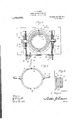
- Fig. 5 is a perspective of one of the holding rings.
- Fig. 6 is an enlarged sectional view illustrating the sliding connection of the supporting blocks.
- Fig. 7 is a sectional view through the supporting structure illustrating the operating means for Referring particularly to the accompanying drawings, 1 represents a furnace open at the top and having a discharge opening or .orifice 2 at the bottom.
- the furnace is preferably heated by gas or suitable fuel led in through the pipes 3.
- walls 4 formed immediately adjacent the furnace proper with spaced parallel ribs 5 having their opposing surf-aces undercut to form a guide way 6.
- the pot proper which is constructed of fire clay or similar refractory material, comprises a cylindrical body 7 closed at the bottom and open at the top. Spaced from thecircular wall of the body is a second wall 78, vertical ribs 9 connecting the walls and providing therebetween a space 10 'for the passage of the heat.
- the wall 8 is provided with anannular ofis t .11 extending around the same and terminating inwardly beyond the respectlve edges of the wall, as shown.
- holding rings 12 made up of semi-circular sections with their ends adapted for connection by means of 'pins 13 passing through openings 14 in the respective ends.
- the sections of the ring have upper and lower inwardly extending flanges 15, adapted when the ring is in place to engage over the opposite end edges of the projection 11 on' the pots.
- Each ring section is provided with a hollow sleeve like projection 16 in which is secured a half round member 17
- Two of the holding rings are used one for each pot and the half round members 17 are placed in contact and secured in such rela t'ion by nuts18, so that the duplicate pots are provided with opposing trunnions, as will be apparent from the drawings.
- each side of the furnace Slidably mounted in the guideways 6 on each side of the furnace are supportingblocks 18, the upper ends of which are provided with spaced U-shaped bearing sections. 19.
- the bearing sections 19 are designed to receive the respective trunnions to rotatably support the pots, and beyond I prefer to pro- "ide each trunnion intermediate the respective bearings 19 with annular members or disks 20 by means of which the pots may be rotated in their respective bearings.
- blocks 18 are provided with longitudinally extending projections 21 on opposite sides of which are arranged gear teeth 22, thereby providing each block with opposing gear racks.
- An operating shaft 23 is supported in bearings 24: beyond the furnace and is provided with a gear 25.
- Rotatably supported upon the- Walls 4 immediately adjacent the blocks 18 are'gears 27 said gears being on opposite sides of the blocks and intermeshing beyond the face of the block.
- each gear 27 is fixed carthe mechanism just described simultaneously 7 operated both blocks 18 thereby elevating the pots above or lowering them into the furnace as may be necessary;
- the shaft 23 beyond the furnace is provided with a' series of radiating projections 29 any one of which is adapted to receive a hollow operating rod 30 whereby the shaft may be rotated to in sure its operation.
- the parts may be elevated and readily inverted for dumping purposes and the pot from which the material has just been discharged returned to the furnace in inverted condition to discharge the residue of the material therefrom.
- each of said pots including an open ended receptacle and-an outer wall surrounding the Wall of the receptacle and JOHN T.
Landscapes
- Chemical & Material Sciences (AREA)
- Engineering & Computer Science (AREA)
- Materials Engineering (AREA)
- Organic Chemistry (AREA)
- Muffle Furnaces And Rotary Kilns (AREA)
Description
C. PAQUET.
GLASS WORKING APPARATUS.
APPLICATION FILED JAN-3,1914.
Patented Apr. 20, 1915.
3 SHEETSr-SHBET 1.
C. PAOUET.
GLASS WORKING APPARATUS. APPLICATION FILED JAN- 3. 1914.
Patented Apr. .20, 1915.
3 SHEETS-SHEET 2.
C. PAQ'UET.
GLASS WORKING APPARATUS.
APPLICATION FILED lAN.3. 1914.
:Patented Apr. 20, 1915.
3 SEEETSSHEBT 3.
wi'wem elevating the pots.
CHABLES BA QU 'ET, 0F OKMULGEE, OKLAHOMA.
GLASS-WORKING- APPARATUS.
Specification of Letters Patent.
Patented Apr. 20, 1915.
A plication filed January 3, 1914. Serial No. 810,200.
To all whom it may concern:
Be it known that I, CHARLES PAQUET, a
citizen of the United States, residing at Okmulgee, in the county of Okmulgee and State of Oklahoma, have invented new and useful Improvements in Glass-Vvorking Apparatus, of which the following is a specilication.
The invention relates to an improvement in glass working apparatus, and particularly handling material for window glass blowing machines, the construction providing a pot which may be kept at uniform. and proper temperature, and which may be readily and conveniently handled under any and all conditions. v
The invention in the preferred formv of details will be described in the following specification, reference being had particularly to the accompanying drawings, in which Figure 1 is a view in elevation illustrating the improvement. Fig. 2 is a plan of the same. Fig. 3 is a vertical section of the same, Fig. 4 is a perspective of one of the pots. Fig. 5 is a perspective of one of the holding rings. Fig. 6 is an enlarged sectional view illustrating the sliding connection of the supporting blocks.
Fig. 7 is a sectional view through the supporting structure illustrating the operating means for Referring particularly to the accompanying drawings, 1 represents a furnace open at the top and having a discharge opening or .orifice 2 at the bottom. The furnace is preferably heated by gas or suitable fuel led in through the pipes 3. Beyond the furnace proper are arranged walls 4 formed immediately adjacent the furnace proper with spaced parallel ribs 5 having their opposing surf-aces undercut to form a guide way 6.
The pot proper, which is constructed of fire clay or similar refractory material, comprises a cylindrical body 7 closed at the bottom and open at the top. Spaced from thecircular wall of the body is a second wall 78, vertical ribs 9 connecting the walls and providing therebetween a space 10 'for the passage of the heat. The wall 8 is provided with anannular ofis t .11 extending around the same and terminating inwardly beyond the respectlve edges of the wall, as shown. In providing the improvement, I' arrange two such pots with their bottoms in contactso that the completed arrangement presents opposing pots opening in opposite directions as"clearly shown in the drawings. As a means for sustaining the pots I provide holding rings 12 made up of semi-circular sections with their ends adapted for connection by means of 'pins 13 passing through openings 14 in the respective ends. The sections of the ring have upper and lower inwardly extending flanges 15, adapted when the ring is in place to engage over the opposite end edges of the projection 11 on' the pots. Each ring section is provided with a hollow sleeve like projection 16 in which is secured a half round member 17 Two of the holding rings are used one for each pot and the half round members 17 are placed in contact and secured in such rela t'ion by nuts18, so that the duplicate pots are provided with opposing trunnions, as will be apparent from the drawings.
Slidably mounted in the guideways 6 on each side of the furnace are supportingblocks 18, the upper ends of which are provided with spaced U-shaped bearing sections. 19. The bearing sections 19 are designed to receive the respective trunnions to rotatably support the pots, and beyond I prefer to pro- "ide each trunnion intermediate the respective bearings 19 with annular members or disks 20 by means of which the pots may be rotated in their respective bearings. The
The shaft on which each gear 27 is fixed carthe mechanism just described simultaneously 7 operated both blocks 18 thereby elevating the pots above or lowering them into the furnace as may be necessary; The shaft 23 beyond the furnace is provided with a' series of radiating projections 29 any one of which is adapted to receive a hollow operating rod 30 whereby the shaft may be rotated to in sure its operation.
From the above construction it will be i obvious that While the material of one pot is being heated in the furnace, the other pot being inverted will be open to the direct application of the heat to the material and such material therein will run from'the pot and into the bottom of the furnace escaping throughthe aperture 2.
By reason of the me hanism described, the parts may be elevated and readily inverted for dumping purposes and the pot from which the material has just been discharged returned to the furnace in inverted condition to discharge the residue of the material therefrom..
What is claimed is 1. The combination wlth a furnace, of blocks vertically movable With relation Copies of this patent may be obtained for thereto, plicate holding rings rotatably supported in the bearings, and a melting pot secured in eachring, said pots being reversed with relationto each other, each of said pots ineluding an' open ceptacle and spaced therefrom.
2. The combination With a furnace, of blocks vertically movable with relation thereto, bearings carried by the blocks, duplicate holding rings rotatably supported in a melting pot secured in each the bearings,
ring, said pots being reversed with relation to each other, each of said pots including an open ended receptacle and-an outer wall surrounding the Wall of the receptacle and JOHN T. HALL, CHESTER MnJLsPAUcH five cents each, by addressing the Commissioner of Patents,
Washington, D. 0.
ended receptacle and an outer Wall surrounding the Wall of the re- 1 bearings carried by the blocks, du-
vso
Priority Applications (1)
| Application Number | Priority Date | Filing Date | Title |
|---|---|---|---|
| US81020014A US1136832A (en) | 1914-01-03 | 1914-01-03 | Glass-working apparatus. |
Applications Claiming Priority (1)
| Application Number | Priority Date | Filing Date | Title |
|---|---|---|---|
| US81020014A US1136832A (en) | 1914-01-03 | 1914-01-03 | Glass-working apparatus. |
Publications (1)
| Publication Number | Publication Date |
|---|---|
| US1136832A true US1136832A (en) | 1915-04-20 |
Family
ID=3204936
Family Applications (1)
| Application Number | Title | Priority Date | Filing Date |
|---|---|---|---|
| US81020014A Expired - Lifetime US1136832A (en) | 1914-01-03 | 1914-01-03 | Glass-working apparatus. |
Country Status (1)
| Country | Link |
|---|---|
| US (1) | US1136832A (en) |
-
1914
- 1914-01-03 US US81020014A patent/US1136832A/en not_active Expired - Lifetime
Similar Documents
| Publication | Publication Date | Title |
|---|---|---|
| US1136832A (en) | Glass-working apparatus. | |
| US846316A (en) | Machine for making window or plate glass. | |
| US1249868A (en) | Glass-drawing apparatus. | |
| US900291A (en) | Blast-furnace. | |
| US1015522A (en) | Pot-furnace. | |
| US759329A (en) | Glass-drawing apparatus. | |
| US1183697A (en) | Glass-drawing apparatus. | |
| US979935A (en) | Glass-furnace. | |
| US1125949A (en) | Ore-roasting furnace. | |
| US2077169A (en) | Furnace | |
| US1171500A (en) | Crucible-furnace. | |
| US563293A (en) | Glass-tank furnace | |
| US1173590A (en) | Heat-treating apparatus. | |
| US39786A (en) | Improvement in furnaces f | |
| US1251038A (en) | Gas-producer. | |
| US268213A (en) | Glass-furnace | |
| US471617A (en) | Apparatus for treating refractory ores | |
| US1124823A (en) | Glass-drawing apparatus. | |
| US414608A (en) | Ground-bone furnace | |
| US236037A (en) | Assay-furnace | |
| US822212A (en) | Method of drawing sheet-glass. | |
| US541718A (en) | Iohhis peters co | |
| US786033A (en) | Reversing-valve. | |
| US1166025A (en) | Drawing glass cylinders. | |
| US680726A (en) | Heating-furnace. |