US1136823A - Sewing-machine. - Google Patents
Sewing-machine. Download PDFInfo
- Publication number
- US1136823A US1136823A US57637610A US1910576376A US1136823A US 1136823 A US1136823 A US 1136823A US 57637610 A US57637610 A US 57637610A US 1910576376 A US1910576376 A US 1910576376A US 1136823 A US1136823 A US 1136823A
- Authority
- US
- United States
- Prior art keywords
- arm
- needle
- machine
- bell crank
- crank lever
- Prior art date
- Legal status (The legal status is an assumption and is not a legal conclusion. Google has not performed a legal analysis and makes no representation as to the accuracy of the status listed.)
- Expired - Lifetime
Links
Images

Classifications
-
- D—TEXTILES; PAPER
- D05—SEWING; EMBROIDERING; TUFTING
- D05B—SEWING
- D05B3/00—Sewing apparatus or machines with mechanism for lateral movement of the needle or the work or both for making ornamental pattern seams, for sewing buttonholes, for reinforcing openings, or for fastening articles, e.g. buttons, by sewing
- D05B3/02—Sewing apparatus or machines with mechanism for lateral movement of the needle or the work or both for making ornamental pattern seams, for sewing buttonholes, for reinforcing openings, or for fastening articles, e.g. buttons, by sewing with mechanisms for needle-bar movement
Definitions
- This invention has for its object a sewing machine which is known as a so-called embroidery sewing machine.
- a sewing machine which is known as a so-called embroidery sewing machine.
- the device for laying the ornamental thread and the laterally moving needle were hitherto each provided with a separate operating mechanism.
- this invention a substantial simplification of the machine is obtained, and this consists in the ornamental thread carrying device and the lateral movement of the needle being operated by a member common to both which is moved by the driving gear of the machine.
- a cam disk is provided which in a suitable manner acts on a bell crank lever which in turn is coupled by links or the like on the one hand with the thread placer and on the other hand with the needle, while the up and down movement of the sewing needle takes place in the ordinary way.
- the sewing machine comprises a. supporting frame 1 on which is mounted a work support 2. Pivotally connected to abracket attached to the frame is a bell crank lever 3.
- This bell crank lever 3 has a short arm 4 which carries a roller 5 running in a cam path 6 of a disk 7.
- the disk 7 is mounted on a stub shaft carried by the frame and is rotated by toothed wheels 9--9, one of which is attached to the disk and the other of which is carried by the main driving shaft of the machine.
- the bell crank lever 3 has an outwardly extending arm 10 and attached to the arm 10 is a second arm 11 which is deflected downwardly and extends beyond the end of the arm 10.
- This toothed sector 14 gears with a similar toothed sector 15 which is sleeved on the presser bar 16 carrying the presser foot 17 and the ornamental thread carrier 19 is removably secured to the arm 18 of this toothed sector 15.
- the lower end of this thread carrier arm 19 is provided with perforations 20 through which the ornamental thread is passed.
- the arm 10 of the bell crank lever 3 is connected by a link 22 to an arm 21 and the arm 21 is in turn connected by an arm 24 with the needle bar guide or gate 24.
- the needle bar 23 reciprocates in this needle gate and the needle gate is mounted to swing on the pin 13.
- the arm 21 is also pivoted to swing about the axis of the pin 13.
- the needle bar has its up and down motion imparted to it in the ordinary way from the main driving pulley through a link connection with the needle lever 26 which in turn is connected to the needle bar.
- Suitable guides 27 and 28 are provided for the ornamental thread which is fed double in the ordinary way through the perforations 20.
- a sewing machine including in combination a driving shaft, a laterally movable needle, an oscillating thread guide, a single bell crank lever, devices for oscillating said lever from said driving shaft, said lever having two arms, devices for connecting one of said arms to the needle for moving the same laterally and devices for connecting the other arm to the thread guide for oscillating the same.
- a sewing machine including in combinationa. driving shaft, a laterally movable needle, an oscillating thread guide, a' single bell crank lever, devices for oscillating said bell crank lever from said driving shaft, said bell crank lever having a long arm and a short arm, devices for connecting the short arm with the needle bar for moving the same laterally and devices for connecting the long arm with the oscillating 'thread guide for oscillating the same.
Description
c. MAIER. j( SEWING MACHINE.
APPLICATION FILED AUG.9. i910.
L, Patented Apu 20, 1915.
2 SHEETS-SHEET 1.
lll f C. MAIER.
SEWING MACHINE.
APPLlcMloN man AUG.9. |910.
Patented A101220, 1915.A
2 SHEBTBSEBET 2 IIIIII IJ mmu,
UNITED STATES PATENT oEEicE.
CARL MAIER, 0F STUTTGART, GERMANY, ASSIGNOR T0 THE FIRM 0F UNION SPECIAL- MASCHINENFABBIK G. M. B. H., 0F STUTTGART, GERMANY.
SEWING-MACHINE.
Specification of Letters Patent.
Patented Apr. 20, 1915.
To all whom 'tmay concern.'
Be it known that I, CARL MAIER, a c1t1zen of the German Empire, residing at Stuttgart, in the Kingdom of Wurttemberg, Empire of Germany, have invented certain new and useful Improvements in Sewing-Machines; and I do hereby declare the following to be a full, clear, and exact descr1pt1on of the invention, such as -will enable others skilled in the art to which it appertams to make and use the same.
This invention has for its object a sewing machine which is known as a so-called embroidery sewing machine. In such machines the device for laying the ornamental thread and the laterally moving needle were hitherto each provided with a separate operating mechanism. Now by this invention a substantial simplification of the machine is obtained, and this consists in the ornamental thread carrying device and the lateral movement of the needle being operated by a member common to both which is moved by the driving gear of the machine. In order to obtain this, a cam disk is provided which in a suitable manner acts on a bell crank lever which in turn is coupled by links or the like on the one hand with the thread placer and on the other hand with the needle, while the up and down movement of the sewing needle takes place in the ordinary way.
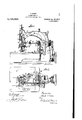
The improvement will now be more particularly explained in one form of construction as an example in connection with the accompanying drawings, in which Figure 1 is a front view of the ornamental seam sewing machine complete; Fig. 2 is a plan view partially in section; while Fig. 3 is a plan view on an enlarged scale of the principal parts of the machine in the position in which the parts are during the stitching down of the ornamental thread; and Fig. 4, a plan view on an enlarged scale of the principal parts in their position when laying the ornamental thread.
The sewing machine comprises a. supporting frame 1 on which is mounted a work support 2. Pivotally connected to abracket attached to the frame is a bell crank lever 3. This bell crank lever 3 has a short arm 4 which carries a roller 5 running in a cam path 6 of a disk 7. The disk 7 is mounted on a stub shaft carried by the frame and is rotated by toothed wheels 9--9, one of which is attached to the disk and the other of which is carried by the main driving shaft of the machine. The bell crank lever 3 has an outwardly extending arm 10 and attached to the arm 10 is a second arm 11 which is deflected downwardly and extends beyond the end of the arm 10. The arm 11 1s connected by a link 12 with a toothed sector 14 mounted to oscillate upon a fixed pm 13. This toothed sector 14 gears with a similar toothed sector 15 which is sleeved on the presser bar 16 carrying the presser foot 17 and the ornamental thread carrier 19 is removably secured to the arm 18 of this toothed sector 15. The lower end of this thread carrier arm 19 is provided with perforations 20 through which the ornamental thread is passed. The arm 10 of the bell crank lever 3 is connected by a link 22 to an arm 21 and the arm 21 is in turn connected by an arm 24 with the needle bar guide or gate 24. The needle bar 23 reciprocates in this needle gate and the needle gate is mounted to swing on the pin 13. The arm 21 is also pivoted to swing about the axis of the pin 13. The needle bar has its up and down motion imparted to it in the ordinary way from the main driving pulley through a link connection with the needle lever 26 which in turn is connected to the needle bar. Suitable guides 27 and 28 are provided for the ornamental thread which is fed double in the ordinary way through the perforations 20.
Assuming the parts to be in the positions shown in Figs. 1 and 3, the operation of the machine is as follows: A rotation of the cam disk 7 oscillates the bell crank lever 3 on its axis 29 and this oscillation of the bell crank lever 3 through the link 22 and the arm 21 swings the needle bar guide or gate thus vibrating the needle laterally and at the same time through the arm 11 swings the sectors 14 and 15 so as to move the ornamental thread guide to the other end of its stroke. When the needle is moved in one direction through the action of the bell crank lever 3, the ornamental thread guide will be moved in the opposite direction. The ornamental thread is laid in front of the needle and is stitched to the fabric by. stitching threads of the machine.
I claim 1. A sewing machine including in combination a driving shaft, a laterally movable needle, an oscillating thread guide, a single bell crank lever, devices for oscillating said lever from said driving shaft, said lever having two arms, devices for connecting one of said arms to the needle for moving the same laterally and devices for connecting the other arm to the thread guide for oscillating the same.
2. A sewing machine including in combinationa. driving shaft, a laterally movable needle, an oscillating thread guide, a' single bell crank lever, devices for oscillating said bell crank lever from said driving shaft, said bell crank lever having a long arm and a short arm, devices for connecting the short arm with the needle bar for moving the same laterally and devices for connecting the long arm with the oscillating 'thread guide for oscillating the same.
3. A sewing machine including in combi- In testimony whereof I aiiix my signature,
in presence of two Witnesses.
CARL MAIER. Witnesses:
HERMANN WmTHCHTERs, FRANZ GAUPP.
Priority Applications (1)
| Application Number | Priority Date | Filing Date | Title |
|---|---|---|---|
| US57637610A US1136823A (en) | 1910-08-09 | 1910-08-09 | Sewing-machine. |
Applications Claiming Priority (1)
| Application Number | Priority Date | Filing Date | Title |
|---|---|---|---|
| US57637610A US1136823A (en) | 1910-08-09 | 1910-08-09 | Sewing-machine. |
Publications (1)
| Publication Number | Publication Date |
|---|---|
| US1136823A true US1136823A (en) | 1915-04-20 |
Family
ID=3204927
Family Applications (1)
| Application Number | Title | Priority Date | Filing Date |
|---|---|---|---|
| US57637610A Expired - Lifetime US1136823A (en) | 1910-08-09 | 1910-08-09 | Sewing-machine. |
Country Status (1)
| Country | Link |
|---|---|
| US (1) | US1136823A (en) |
Cited By (1)
| Publication number | Priority date | Publication date | Assignee | Title |
|---|---|---|---|---|
| US2500211A (en) * | 1947-06-07 | 1950-03-14 | Man Sew Corp | Sewing machine |
-
1910
- 1910-08-09 US US57637610A patent/US1136823A/en not_active Expired - Lifetime
Cited By (1)
| Publication number | Priority date | Publication date | Assignee | Title |
|---|---|---|---|---|
| US2500211A (en) * | 1947-06-07 | 1950-03-14 | Man Sew Corp | Sewing machine |
Similar Documents
| Publication | Publication Date | Title |
|---|---|---|
| US1136823A (en) | Sewing-machine. | |
| US1613605A (en) | Looper mechanism for sewing machines | |
| US3745951A (en) | Needle driving device for sewing machines | |
| US2035508A (en) | Feeding mechanism for sewing machines | |
| US1088339A (en) | Sewing-machine. | |
| US1339243A (en) | Sewing-machine | |
| US225199A (en) | William m | |
| US1386322A (en) | Looper mechanism for sewing-machines | |
| US1042537A (en) | Sewing-machine. | |
| US1263239A (en) | Sewing-machine. | |
| US1081596A (en) | Thread-controller for sewing-machines. | |
| US420191A (en) | Half to thomas a | |
| US1046401A (en) | Sewing-machine. | |
| US1792722A (en) | Sewing machine | |
| US1879449A (en) | Sewing machine | |
| US2156525A (en) | Feed mechanism for sewing machines and the like | |
| US1302219A (en) | Sewing-machine. | |
| US721078A (en) | Looper mechanism for sewing-machines. | |
| US1236599A (en) | Overseaming-machine. | |
| US1124323A (en) | Sewing-machine. | |
| US753187A (en) | A coepoea | |
| US983264A (en) | Buttonhole-sewing attachment for sewing-machines. | |
| US403163A (en) | weiss | |
| US998770A (en) | Overseaming sewing-machine. | |
| US674614A (en) | Looper mechanism for sewing-machines. |