US1136814A - Automatic direction-indicator. - Google Patents
Automatic direction-indicator. Download PDFInfo
- Publication number
- US1136814A US1136814A US83044214A US1914830442A US1136814A US 1136814 A US1136814 A US 1136814A US 83044214 A US83044214 A US 83044214A US 1914830442 A US1914830442 A US 1914830442A US 1136814 A US1136814 A US 1136814A
- Authority
- US
- United States
- Prior art keywords
- arrows
- casing
- frame
- plate
- operating
- Prior art date
- Legal status (The legal status is an assumption and is not a legal conclusion. Google has not performed a legal analysis and makes no representation as to the accuracy of the status listed.)
- Expired - Lifetime
Links
Images

Classifications
-
- B—PERFORMING OPERATIONS; TRANSPORTING
- B60—VEHICLES IN GENERAL
- B60Q—ARRANGEMENT OF SIGNALLING OR LIGHTING DEVICES, THE MOUNTING OR SUPPORTING THEREOF OR CIRCUITS THEREFOR, FOR VEHICLES IN GENERAL
- B60Q1/00—Arrangement of optical signalling or lighting devices, the mounting or supporting thereof or circuits therefor
- B60Q1/26—Arrangement of optical signalling or lighting devices, the mounting or supporting thereof or circuits therefor the devices being primarily intended to indicate the vehicle, or parts thereof, or to give signals, to other traffic
- B60Q1/34—Arrangement of optical signalling or lighting devices, the mounting or supporting thereof or circuits therefor the devices being primarily intended to indicate the vehicle, or parts thereof, or to give signals, to other traffic for indicating change of drive direction
- B60Q1/36—Arrangement of optical signalling or lighting devices, the mounting or supporting thereof or circuits therefor the devices being primarily intended to indicate the vehicle, or parts thereof, or to give signals, to other traffic for indicating change of drive direction using movable members, e.g. arms with built-in flashing lamps
Definitions
- Another important object of my invention is to proi'iilo ioi'ol inc-ans for controlling the i-in-uiis i'm'llie magncts ⁇ VlllCll will cause both indicating IH'l'U'i lo mowoniwanlly from ilw casing at right angles llHHU) so ilh to iin'l ralc tlio intoniion of til cli-iw-i- 1o ⁇ lop, nail nwznw 3 *ing lOlliEOiliPl Specification c-t" Lenora:
- ion is to clcscribcd i pemi3io1n A.
- mnhoo-i oi to shocks the road- 1' in: ant, .iiels, and Joly (the; p to an niifactazfc and The above. :ml additional objects are zarcoinplishcil o such means as are lllllS- 'i'liiiOLl u zu-conipanying drawings, de-
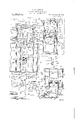
- Figure 1 is a iUilleiillzllll fl "in-Wing the device as it in'z'isscmblcal posii-ion moment to the rear of f portion of the license 7 1' 'rlicil to t clc'vicc ii i z'tion of llic ilovico to in; attacl mi it.
- Q is a scc onal vii-w iaiwn iln'ou mechanism.
- Fig. 9 15 lo (Ya i closm mechaa longitudinal vertical section of'the circuit 15
- the casing l' is provided upon its front wall with opening to provide for the connection or the mechanism contained in the casing with the indicating arrows and respectively.
- a rectangular cover 2 plate l is secured at its angular end to the front wall of the casing 1 in spaced relation thereto and scrr to cover the arrows A and B when the arrows are in down position.
- a rear light compm'tment designated 6 as an entirety iormcd on the lower part oi the main c ing land comprises a suitable lens '7 a'udan electric lamp 8.
- the lower wall of this comparti'nent' 6' is open as at 93 throughout its length to permit the lamp 8 therein to suliiciently illuminate a license number plate 10 thatis secured upon the main casing l by an li-shaped brachet 11, so as to receive the light from the compartment 6.
- the indicating arrows A and B are formed in the nature of hollow rectangular casings and each contain a plurality of electric lamps 12.
- the -trout Wall of each arrow is formed of terial preferably glass to permit the lamps 12 to properly illuminate the arrow outlines at night, while the body portion of the arrows is preferably constructed of some light metal.
- the arrows are swingin gly connected at their upper ends with the mechanism contained within the casing for operating the same and to he later described,
- Band '6 consists of a pair of vertically arranged electromagnets 13 that are arranged within the casing 1 and preferably secured to the bottom wall thereof in any su. hie manner.
- a sh Arranged within the casing and surrounding the magnets 13 is a sh.
- a frame work for supporting the operating mechanism which consists of four vertica lower terminals i any suitable manner to the lower portion of the casing 1 and con nected in pairs by angular connecting; bars some suitable transparent ma-- I standards 1% secured at their 15 and 16 which are secured at their termi- Mounted upon the standards 14' is the mechanism for operating each arrow and is designated as an entirety by the numerals 17 and 18 respectively.
- This mechanism 17 and 18 is similar in construction and arrangement and it is thought necessary to describe the mechanism for operating only one arrow in this connection;
- the numeral 19 designates a preferablyrectangular plate which is slidaoly mounted upon two of the standards 1 that are arranged upon opposite sides of the magnets 1'3 for operating the mechanism 18.
- This plate 19 is arranged transversely of the standards 1% and is adapted to .be at 'tracted by the magnets 13 adjacent thereto and disposed'heneath the plate.
- Mounted above the plate 19 for sliding movement on the standards 1% upon which the plate 19 is mounted is a similarly shaped plate 20 having friction rollers 21 journaled in bearings 22 at each end thereof that are adapted for engagement with the standards l ito permit the free sliding movement of the plate 20.
- the spring catches 25 are ofiset to provide hooks 2-7 that engage the under face of the plate 20, normally, and hold the plates 19 and 20 against accidental movement.
- openings 26 in the top plate 20 are of considerably greater size than the hooks 27 on the free ends of the members 25 to permit the ready disengaging of the hooks 27 fromthe plate 20.
- the spring action of the spring catches 25 tends to force the catches outwardly from the standards 11 so that the hooks 27 are normally disposed in sup: porting and locking engagement with the plate '20.
- bars 15 and 16 Journaled transversely of the'connecting. bars 15 and 16 is a plurality of shafts 28, 29,
- the shafts 29 and 30 are extended forwardly through the front wall of the casing l and rigidly secured in any suitable manner to, the arrows Band A respectively so that a movement of the shafts 29 and 30 produces a subsequent movement of the arrows B and A.
- the shaft 28 is operatively connected with the mechanism 17 for operating the arrow B and the shaft 31 is like wise connected to the mechanism 18 for op erating the arrow A.
- Mounted intermediate its ends upon the shaft 31 is a bell crank lever 32.- One arm of his bell crank lever is pivotally connected with the upper terminal of a' vertical operating rod 33 that is connected at its lower end in any suitable manner to the central portion of the upper plate 20.
- the upper portion of the rod 33 is provided with a U-shaped bracket 3a in which the aforementioned arm of the bell crank lever 32 is pivoted by means of a pivot pin journaled through the arm of the bracket.
- Mountedor formed on the shaft 30 is a short arm 85 that is connected with the other arm of the bell crank lever 32 by means of a link 36 pivoted at its end to the aforementioned arm.
- the short arm 35 is normally in a vertical position and is rigidly secured to the shaft 30 so that its movement in a plane of 90 degrees is sufficient to cause the arrow A to move to full extended position.
- a contact member 38 of some suitable contacting metal that is adapted to co iperate with a contact member 39.
- These contacts 38 and 39 are adapted for cooperation with each other when the arrow A is ioved into extended signaling position to cause the lamps 12 in the arrow to be illuminated.
- Conducting wires to be later described are suitably connected with these contacts 38 and 3..
- a U-shaped frame ail This frame a9 is pivotally supported so that its arms are disposed in a horizontal plane relative to the standards 14;
- An angular bracket 11 having a sleeve portion 42 on one end slidably mounted on one of the standards 14 and provided with a set screw 43 supports the U-shaped frame.
- a pair of these brackets 41 is provided and each bracket is slidably mounted after the manner described on the members
- a pair of frames 40 is necessary for the proper operation of both catches 25 and each pair is connected by a.
- horizontal integral rod a l. T is rod i-l is extended beyond the lowermost of the arms of the frame and is pivotally mounted in the free vertical terminal d5 of the bracket 41.
- -A right angular extension 46 is formed on the intermediate portion of the bracket 1-1 and has connected therewith a helical retractile spring s17.
- This spring is connected at its other terminal to an extension 48 on each frame that is disposed above the pivot connection of the frame.
- the lowermost of the arms +29 of each frame 40 is disposed in an inclined plane relative to the horizontal of device and extends in an angular position between the magnets 3 and plate 19.
- This arm 49 on each frame is disposed upon opposite sides of the magnets and engages at its free end. the under face of the plate 19 adjacent the ends of the plate 19, thus the plate 19 is permitted free downward movement without interference by the arms 49.
- the uppermost of the arms 50 of each frame is curved and disposed in a downwardly inclined plane and adapted for engagement with projections 51 carried intermediate the ends of the catches
- This projection 51 is provided with an outer inclined face that is adapted for engagement with the arm 50 when the frames are swung thus moving the catches 25 in a position so that the plate 20 is free to move relative to the books 27 on the ends of the catches 25 and the desired operation of extending the in-. dicating arrows is had.
- the magnets 13 are energized the plate 19 which is normally in a position such as illustrated in Fig. 1, in that the heads 24 of the pins 23 are spaced from the plate 20 thus permitting movement of the plate 19, in being attracted by the magnets moves downwardly and in so doing forces the arms 4:9 of each frame LO downwardly so that the frames 40 swing on their pivot 1 position such as illustrated in Fig. 3 in the drawings.
- an arcuate supporting frame 53 having an ear 5% intermediate its ends adapted for cotiperation with an ear 55 on a rectangular securing plate 56.
- the plate 56 is bolted as at 57 to the dash boa rd or some other suitable part of the automobile adjacent the drivers seat.
- a pin 58 is inserted through the cars 54 and 55 and has a winged nut 59 carried upon its unheaded terminal for the purpose of securing the arcuate frame 53 in the desired position.
- the frame 53 is positioned so as to nearly encircle the steering column 60 of the steering gear of the automobile. Secured upon theends of the arcuate.
- contact plates 61 which are suitably insulated as at 62 from the frame 53. These contact plates 61 are of suflicient length to permit the desired operation of the mechanism when the driver'contemplates taking a turn, and are approximate 7 equivalent in length to 90 degrees of the arc of rota-' tion'of the steering column. Bindingposts 63 are arranged upon the contacts 61 intermediate the ends thereof. Fixed upon the steering column 60 and adapted to rotate therewith is a contact arm 64 having an 1ntegral securing collar 65 at one end and an enlarged contact head 66 at its free end.
- the free end 66 is adapted to engage the contacts 61 when thesteering column is ro-' tated.
- a binding post 67 is secured tothe hub portion 65 or the arm. Insulation 68 is interposed between the collar 65 andsteering column 60.
- circuit cldsing mechanism designated 68 as an entirety and that is suitably mounted adjacent the drivers seat upon the floor board of the automobile or other suitable place.
- This circuit closing mechanism (38 is illustrated in Fig.,10 in the drawings and consists of a casing 69 having securing flanges 7 0 adjacent one end thereof which is open. The open end of the casing 60 is adapted to be secured to some suitable part ofthe auto-' mobile and has interposed between it and theautomobiic a strip or layer of insulation 71.
- a contact bar 72 having a binding post 73 on one end thereof.
- spring contact members 74 Suitably secured or connected with the contact her 72 are spaced spring contact members 74:. These spring arms 4 extend outwardly-into the casing 69 for a distance'equivalent to half the lengthof the casing. T he casing'is provided centrally of 78 and a detachable securing collar 79 into.
- Binding posts 79" and 7 9 are arranged upon opposite sides of the casing 69 -and are suitably connected with spiral expansive springs 80 that are arranged within the casing 69 and normally spaced from the contact arms 74. It will be readily seen that when the plunger 76 is pushed inwardly with relation to the casing and en- 77 is connected with the plunger gages the contact arms 74, the contact arms 7% will be forced apart so as to cnga' e the I springs 80' thus closin the circuit a tone. manner which will be later more fully described. i i Referring particularly to Fig.
- FIG. 3 wherein there is illustrated a diagrammatic view of Zhe electrical circuit for operating the mechnismthe rear lamp 8 receives its current rom abatteryor some other suitable source 0 through a conductor wire 81 that is conhected with the lamp 8-,. and battery 80 and i second conductor wire 82 which is conelected at one end with the lamp 8 is secured so a binding post 83 on the bottom part of he casing 1 and from the binding post ex some other suitable part or the automobile where it is accessible.
- the circuit for operating the mechanism 17 and arrow B and for operating the mechanism 18 relative to'thearrow A consists" of a conductor wire 85 that'is connected with the wire .82 adjacent the battery terminal thereof and is provided at its other end with branch conducting wires 85 and 87 which respectively connect with the magnets 13 of each'm 'e'chanism 17 and 18.
- branch conducting wires 85 and 87 which respectively connect with the magnets 13 of each'm 'e'chanism 17 and 18.
- Oneside of the circuit is thus apparent through the medium of. the main conducting wire 85 and branch conductors 86 and 82'.
- the second conductingi wire for the magnets 13 for'operating the mechanism 17, consists of a-conducting length 88 which'is connected at its terminals to the niagnets'and to wim 89 that is connected with one ofthec'ontact members 61 of the automatic'circuit closing mechanism on th e steering post which is illustrated' in diagram in Fig. 3 and 'designated 90." It. will thus be seen that when the contact arm: 65L is'in engagement witli the-ileft me als tactSl in Fig. 3, the circuit is closed relative to-the magnet-s 13fo1' operating the mechanism 17 through the conducting wires 88 and 89, 85 and 87 as hereinbefore described.
- T he switch arm 6% is connected to the lamp conductor 81 adjacent its battery terminal by means of a conducting length -91 thus completing the circuit relative to the left hand magnet 13.
- the second conducting line for theinagnet 13 for operating the mechanism 18 consists of a short conducting .length 92 that is connected with the right and 93.
- conduct ing wires 94 and 95 connect both conductors 89 and 93 with the binding posts 79 and 79 respectively as illustrated in Fig. 10, and a conducting wire 95 is connected at one terminal to the switch arm 6% and at its other terminal to the binding post 73 on the easing 69.
- C ducting wires 97 serve to connect the contacts 39 with the conducting wires 89 and 93.
- Conducting wires 98 connect the contacts 38 and 39 with the lamp 1?- in the arrows A and B as will be clearly seen with reference to Fig. 5 in the drawings.
- the conductor 82 is grounded at the binding post 83 and the current passes through the mechanism to the contacts 38 which are mounted upon the shafts 29 and 30. It will thus be seen that the lamp 12 contained Within the arrows A and B will be illuminated' when the arrows move into extended position, as the circuit for the lamps is closed by the engagement of the contacts 38 with the ones 39. The lamps are illuminated when the stop signal is displayed in a similar manner as will be readily observed by reference to Fig. 3 in the drawings.
- Fig. 3 there has been illustrated means for preventing the arrows from striking each other when swinging into inoperative position.
- This means consists of a bar 99 that is secured in any suitable manner within the casing for the mechanism and has mounted thereon a pair of slidable bufier plates 100.
- the device mav be operated by means of buttons arranged upon the steering wheel of the automobile.
- the pedal 77 is preferablythe brake pedal of the automobile so that when the driver contemplates a stop the-brake pedal is pushed consequently providing the automatic signaling that the driver intends to stop.
- the stop signaling mechanism could be operatively connected thereto.
- a direction indicator comprising acasing to be secured to the rear of an automobile, a pair of indicating arrows swingingly mounted within the casing to be swung outwardly therefrom in horizontal extended position.
- a frame mounted within the easing, said arrows pivotally supported by the frame, electromagnets mounted within the casing.
- a direction indicator comprising a casing td be secured to the rear of an automobile, a pair of indicating arrows swingingly mounted within the casing to be swung outwardly "therefrom in horizontal extended position,' a frame mounted within the casing, said arrows being pivotally supported by the frame, electromagnets mounted within the casing, plates slidably mounted on the frame above the magnets to be attracted thereby, a second set of plates slidably connected with the first plate and slidably mountedon the frame, shafts journaled in the frame for supporting the arrows, means for cdnnecting the shafts with the second set of plates, automatic means for energizing the magnets whereby the plates are moved on said frame and the arrows moved into extended horizontal position from the casing, operated when the automobile makes 'a right or left turn, and means for automatically illuminating the arrows at the time of their disposal in horizontal extended position-relative to the casing.
- a casing to be mounted upon the rear-of an automobile, a pair of indicating arrows swingingly connected with the casing to be swung into horizontal extended position, means mounted within the casing for operating the arrows, a pair of rotatable shafts mounted within the casing and secured at certain of their terminals to the arrows, said shafts operatively connected with the operating mechanism for the arrows, a frame for supporting the operating mechanism and shafts, electric lamps carried by said arrows, a contact member carried by said shafts, a fixed contact member on the frame, said first named contact member normally out of engagement with the fixed contact members, said contacts being operatively connected with a battery circuit and the electric lamps to coiiperate with each other when the arrows move singly ortogether into horizontal extended position, to cause illumination of the arrows.
- a direction indicator for automobiles comprising a casing to be secured to the rear of anautomobile', a pair of indicating arrows, operating means for the arrows mounted within the casing, said arrows swingingly connected with the operating means to be swung from the casing into horizontal extended position, said operating mechanism comprising electromagnets to be energized automatically when the automobile makes a ri ht.or left turn, independently, and simu taneously, means for automatically and independently energizing the magnets operatively connected with the steering gear of the automobile, means for mounted operating means a ainst accidental slidin movement sup orte by said frame, said s i'dably mounte operating means to be attracted by the magnets when the magnets are energized.
- An automobile direction indicator comprising a casing to be secured to the rear.
Landscapes
- Engineering & Computer Science (AREA)
- Mechanical Engineering (AREA)
- Lighting Device Outwards From Vehicle And Optical Signal (AREA)
Description
N. w. KLHNMAN,
AUTOMAUC DIRECTION INDICATDR.
APPLICATION FILED APR. 8, i914.
Patented Apr. 20, 1915.
2 SHEBTS-SHEET l.
N. W. KLEINMAN AUTOMAYIC DIRECTION iNDlCATOR.
1 APPUCATION FILED APR. 8, 1914, j' i3fi gig Patented 5111220, 1915.
2 SHEETSSHEET 2.
'opci'ating I Winn-(by ai-cillmital positioning: of the indi NTHANIEL V]. KLEINMANK. E3901 Application filed- April 3, 161
Z?) all ether/2 I concc'm Be it known at I NATHAN-MEL lV, ilLIZlN- MAN, izen the l nit ecl States, residing at Brooklyn, in the county of Kings and State of New York, nave invcn'mci certain new and useful La n-moments in Automatic Direction inillicatorsz and 1 do hereby do Clare the following to be a full clip; a. min exact description of the invention, such will enable others skillcil in iho art to 'o'i it a ipoi-tains to make and the My invention relates to iinpiovecl moans i'mindicating, fhc direction of of a vehicle to following vehicles ami ifosixles in the provision of a (lc'cico of the character described viicli automatic in ipla'ation. An important object of my invcniion x to provide a device of the. cl: X scribed. which arlapiwl lo be an the roar of an automobile and which plo v's indicating arrowslliat are automatirally swung from opposite sides: of a 0; so as to imlica'le the contemplation oi driver taking a right or left turn or stopping.
Another important objcci of a2 i i to provide novel means for ii; u electric lamps that are oonfainccl \v i 1 indicating arrows, at the time of the i wont of the arrows in the indicati g position. so llia't the signal will be effective at night.
Another ionvoi'tant object oi my inx'wiiion t lHTHiKlO mechanism for opmating tlic :u'n'ms as (lLSClllKil above winch conarrangwmvnz' of vlicn i'noz mow ilzo in gmiiion.
Anotlnr i apoi'iant obit-cl of my inu-ni'ion i; to prm'illc novel means for locking i-lll lliiijl'zllllSiil against inovmncnt vating arrows is prevented.
Another important object of my invention is to proi'iilo ioi'ol inc-ans for controlling the i-in-uiis i'm'llie magncts \VlllCll will cause both indicating IH'l'U'i lo mowoniwanlly from ilw casing at right angles llHHU) so ilh to iin'l ralc tlio intoniion of til cli-iw-i- 1o \lop, nail nwznw 3 *ing lOlliEOiliPl Specification c-t" Lenora:
ion is to clcscribcd i pemi3io1n A. mnhoo-i oi to shocks the road- 1' in: ant, .iiels, and Joly (the; p to an niifactazfc and The above. :ml additional objects are zarcoinplishcil o such means as are lllllS- 'i'liiiOLl u zu-conipanying drawings, de-
foiloa'ing spccifica' ion and -cnlariy pointcitl out U1 the rammed i'illifi anal iorm '1. .w 1 on as in is icoucoci t '22 *ci'encc numcra desig- 1 rcsgmmling pal-is: Figure 1 is a iUilleiillzllll fl "in-Wing the device as it in'z'isscmblcal posii-ion moment to the rear of f portion of the license 7 1' 'rlicil to t clc'vicc ii i z'tion of llic ilovico to in; attacl mi it. c 1 ing ilic i back 0 f arrows sliowii. {z iiliQ :11 H loclwl'l position :Uul the n a :liagrrmnnatio i'oz'nn iv; clm'aiion of ilio operating incclianisin, a top plan \icii' of tlic ogwi-ating "zeclianism showing the arrows attached t nwvlnin cm of ii? automobile showing the vontzn my automatically operating ow i'miici arrows. Fig. Q is a scc onal vii-w iaiwn iln'ou mechanism. Fig. 9 15 lo (Ya i closm mechaa longitudinal vertical section of'the circuit 15 The casing l'is provided upon its front wall with opening to provide for the connection or the mechanism contained in the casing with the indicating arrows and respectively. A rectangular cover 2 plate l is secured at its angular end to the front wall of the casing 1 in spaced relation thereto and scrr to cover the arrows A and B when the arrows are in down position. A rear light compm'tment designated 6 as an entirety iormcd on the lower part oi the main c ing land comprises a suitable lens '7 a'udan electric lamp 8. The lower wall of this comparti'nent' 6' is open as at 93 throughout its length to permit the lamp 8 therein to suliiciently illuminate a license number plate 10 thatis secured upon the main casing l by an li-shaped brachet 11, so as to receive the light from the compartment 6.
The indicating arrows A and B are formed in the nature of hollow rectangular casings and each contain a plurality of electric lamps 12. The -trout Wall of each arrow is formed of terial preferably glass to permit the lamps 12 to properly illuminate the arrow outlines at night, while the body portion of the arrows is preferably constructed of some light metal. The arrows are swingin gly connected at their upper ends with the mechanism contained within the casing for operating the same and to he later described,
and are adapted to he swung outwardly at right angles to the casing'l and plate 1 in a plane parallel to the horizontal axis of the casing, when in indicating position.
The operating mechanism for moving the arrows into indicating position, best illustrated in Figs. 3, 4, Band '6 consists of a pair of vertically arranged electromagnets 13 that are arranged within the casing 1 and preferably secured to the bottom wall thereof in any su. hie manner. Arranged within the casing and surrounding the magnets 13 is a sh. a frame work for supporting the operating mechanism which consists of four vertica lower terminals i any suitable manner to the lower portion of the casing 1 and con nected in pairs by angular connecting; bars some suitable transparent ma-- I standards 1% secured at their 15 and 16 which are secured at their termi- Mounted upon the standards 14' is the mechanism for operating each arrow and is designated as an entirety by the numerals 17 and 18 respectively. This mechanism 17 and 18 is similar in construction and arrangement and it is thought necessary to describe the mechanism for operating only one arrow in this connection;
Referring particularly to Fig. i in which is illustrated the mechanism 18 for operating the arrow A the numeral 19 designates a preferablyrectangular plate which is slidaoly mounted upon two of the standards 1 that are arranged upon opposite sides of the magnets 1'3 for operating the mechanism 18. This plate 19 is arranged transversely of the standards 1% and is adapted to .be at 'tracted by the magnets 13 adjacent thereto and disposed'heneath the plate. Mounted above the plate 19 for sliding movement on the standards 1% upon which the plate 19 is mounted is a similarly shaped plate 20 having friction rollers 21 journaled in bearings 22 at each end thereof that are adapted for engagement with the standards l ito permit the free sliding movement of the plate 20. Vertical pins 23 are secured in, spaced relation adjacent the central portion of the plate 19, are inserted for sliding movement through openings in theupper plate 20 and provided with enlarged heads 2-: at their up per ends of greater sizethan the openings in the plate 20 and which serve to prevent withdrawal of the pins relative to the plate 20. It will thus be seen that when the plate 19 is moved toward the magnets 13 by the attraction of the magnets, the plate 20 is correspondingly moved owingto the pin and slot connection previously described. Mounted upon the standards 14 are spring catches l5 that are secured in spaced parallel relation to the member 14. 'and extend through rec the top plate20 c The free ends ofi' tangular openings 26 in at their free terminals.
the spring catches 25 are ofiset to provide hooks 2-7 that engage the under face of the plate 20, normally, and hold the plates 19 and 20 against accidental movement. The
Journaled transversely of the'connecting. bars 15 and 16 is a plurality of shafts 28, 29,
30 and 31. The shafts 29 and 30 are extended forwardly through the front wall of the casing l and rigidly secured in any suitable manner to, the arrows Band A respectively so that a movement of the shafts 29 and 30 producesa subsequent movement of the arrows B and A. The shaft 28 is operatively connected with the mechanism 17 for operating the arrow B and the shaft 31 is like wise connected to the mechanism 18 for op erating the arrow A. Mounted intermediate its ends upon the shaft 31 is a bell crank lever 32.- One arm of his bell crank lever is pivotally connected with the upper terminal of a' vertical operating rod 33 that is connected at its lower end in any suitable manner to the central portion of the upper plate 20. The upper portion of the rod 33 is provided with a U-shaped bracket 3a in which the aforementioned arm of the bell crank lever 32 is pivoted by means of a pivot pin journaled through the arm of the bracket. Mountedor formed on the shaft 30 is a short arm 85 that is connected with the other arm of the bell crank lever 32 by means of a link 36 pivoted at its end to the aforementioned arm. The short arm 35 is normally in a vertical position and is rigidly secured to the shaft 30 so that its movement in a plane of 90 degrees is sufficient to cause the arrow A to move to full extended position. It will thus be seen that upon the energization of the magnet 13 operating in conjunction with the mechanism 18 for operating the arrow A, and assuming the spring latch 25 to be in unlocked position, the plate 19 is attracted by the magnet and the plate 20 is subsequently moved downwardly causing a pull on the rod 33. When the rod 38 is pulled the bell crank lever 32 is operated which action causes the link 36 to transmit a push to the arm 35 which in turn rotates the shaft 30 and subsequently moves the arrow A into extended signaling position.
The action above described -'of the shaft 30 and cooperating parts is aided materially by a curved weight 37 that is fixed upon the shaft 30 at right angles thereto and is normally poised so that when the spring catch 25 is released the weight moves downwardly.
Mounted upon the weight 37 upon one face thereof is a contact member 38 of some suitable contacting metal that is adapted to co iperate with a contact member 39. carried upon the connecting angle bar 15. These contacts 38 and 39 are adapted for cooperation with each other when the arrow A is ioved into extended signaling position to cause the lamps 12 in the arrow to be illuminated. Conducting wires to be later described are suitably connected with these contacts 38 and 3..
As a means for releasing the spring catches so that the operation of the arrow may be had there is provided a U-shaped frame ail This frame a9 is pivotally supported so that its arms are disposed in a horizontal plane relative to the standards 14; An angular bracket 11 having a sleeve portion 42 on one end slidably mounted on one of the standards 14 and provided with a set screw 43 supports the U-shaped frame. A pair of these brackets 41 is provided and each bracket is slidably mounted after the manner described on the members A pair of frames 40 is necessary for the proper operation of both catches 25 and each pair is connected by a. horizontal integral rod a l. T is rod i-l is extended beyond the lowermost of the arms of the frame and is pivotally mounted in the free vertical terminal d5 of the bracket 41.
-A right angular extension 46 is formed on the intermediate portion of the bracket 1-1 and has connected therewith a helical retractile spring s17. This spring is connected at its other terminal to an extension 48 on each frame that is disposed above the pivot connection of the frame. The lowermost of the arms +29 of each frame 40 is disposed in an inclined plane relative to the horizontal of device and extends in an angular position between the magnets 3 and plate 19. This arm 49 on each frame is disposed upon opposite sides of the magnets and engages at its free end. the under face of the plate 19 adjacent the ends of the plate 19, thus the plate 19 is permitted free downward movement without interference by the arms 49. The uppermost of the arms 50 of each frame is curved and disposed in a downwardly inclined plane and adapted for engagement with projections 51 carried intermediate the ends of the catches This projection 51 is provided with an outer inclined face that is adapted for engagement with the arm 50 when the frames are swung thus moving the catches 25 in a position so that the plate 20 is free to move relative to the books 27 on the ends of the catches 25 and the desired operation of extending the in-. dicating arrows is had.
W hen the magnets 13 are energized the plate 19 which is normally in a position such as illustrated in Fig. 1, in that the heads 24 of the pins 23 are spaced from the plate 20 thus permitting movement of the plate 19, in being attracted by the magnets moves downwardly and in so doing forces the arms 4:9 of each frame LO downwardly so that the frames 40 swing on their pivot 1 position such as illustrated in Fig. 3 in the drawings.
As a means for automatically operating the mechanism hereinbefore described when the vehicle driver contemplates making a turn, there has been provided an arcuate supporting frame 53 having an ear 5% intermediate its ends adapted for cotiperation with an ear 55 on a rectangular securing plate 56. The plate 56 is bolted as at 57 to the dash boa rd or some other suitable part of the automobile adjacent the drivers seat. A pin 58 is inserted through the cars 54 and 55 and has a winged nut 59 carried upon its unheaded terminal for the purpose of securing the arcuate frame 53 in the desired position. The frame 53 is positioned so as to nearly encircle the steering column 60 of the steering gear of the automobile. Secured upon theends of the arcuate. frame 53 are contact plates 61 which are suitably insulated as at 62 from the frame 53. These contact plates 61 are of suflicient length to permit the desired operation of the mechanism when the driver'contemplates taking a turn, and are approximate 7 equivalent in length to 90 degrees of the arc of rota-' tion'of the steering column. Bindingposts 63 are arranged upon the contacts 61 intermediate the ends thereof. Fixed upon the steering column 60 and adapted to rotate therewith is a contact arm 64 having an 1ntegral securing collar 65 at one end and an enlarged contact head 66 at its free end.
The free end 66 is adapted to engage the contacts 61 when thesteering column is ro-' tated. A binding post 67 is secured tothe hub portion 65 or the arm. Insulation 68 is interposed between the collar 65 andsteering column 60.
As ameans for closing the two circuits simultaneously so that the arrows A and B move into signaling position simultaneously and indicate that the driver intends to stop the vehicle, there has been provided circuit cldsing mechanism designated 68 as an entirety and that is suitably mounted adjacent the drivers seat upon the floor board of the automobile or other suitable place. This circuit closing mechanism (38 is illustrated in Fig.,10 in the drawings and consists of a casing 69 having securing flanges 7 0 adjacent one end thereof which is open. The open end of the casing 60 is adapted to be secured to some suitable part ofthe auto-' mobile and has interposed between it and theautomobiic a strip or layer of insulation 71. Mounted within the strip 71 is a contact bar 72 having a binding post 73 on one end thereof. Suitably secured or connected with the contact her 72 are spaced spring contact members 74:. These spring arms 4 extend outwardly-into the casing 69 for a distance'equivalent to half the lengthof the casing. T he casing'is provided centrally of 78 and a detachable securing collar 79 into.
which one end of the plunger 7 6 is threaded. Binding posts 79" and 7 9 are arranged upon opposite sides of the casing 69 -and are suitably connected with spiral expansive springs 80 that are arranged within the casing 69 and normally spaced from the contact arms 74. It will be readily seen that when the plunger 76 is pushed inwardly with relation to the casing and en- 77 is connected with the plunger gages the contact arms 74, the contact arms 7% will be forced apart so as to cnga' e the I springs 80' thus closin the circuit a tone. manner which will be later more fully described. i i Referring particularly to Fig. 3 wherein there is illustrated a diagrammatic view of Zhe electrical circuit for operating the mechnismthe rear lamp 8 receives its current rom abatteryor some other suitable source 0 through a conductor wire 81 that is conhected with the lamp 8-,. and battery 80 and i second conductor wire 82 which is conelected at one end with the lamp 8 is secured so a binding post 83 on the bottom part of he casing 1 and from the binding post ex some other suitable part or the automobile where it is accessible.
The circuit for operating the mechanism 17 and arrow B and for operating the mechanism 18 relative to'thearrow A consists" of a conductor wire 85 that'is connected with the wire .82 adjacent the battery terminal thereof and is provided at its other end with branch conducting wires 85 and 87 which respectively connect with the magnets 13 of each'm 'e'chanism 17 and 18. Oneside of the circuit is thus apparent through the medium of. the main conducting wire 85 and branch conductors 86 and 82'. The second conductingi wire for the magnets 13 for'operating the mechanism 17, consists of a-conducting length 88 which'is connected at its terminals to the niagnets'and to wim 89 that is connected with one ofthec'ontact members 61 of the automatic'circuit closing mechanism on th e steering post which is illustrated' in diagram in Fig. 3 and 'designated 90." It. will thus be seen that when the contact arm: 65L is'in engagement witli the-ileft me als tactSl in Fig. 3, the circuit is closed relative to-the magnet-s 13fo1' operating the mechanism 17 through the conducting wires 88 and 89, 85 and 87 as hereinbefore described. T he switch arm 6% is connected to the lamp conductor 81 adjacent its battery terminal by means of a conducting length -91 thus completing the circuit relative to the left hand magnet 13. The second conducting line for theinagnet 13 for operating the mechanism 18 consists of a short conducting .length 92 that is connected with the right and 93.
Relative to the switch mechanism for closing both circuits and which is particularly illustratedin F ig. 10 in the drawings, conduct ing wires 94 and 95 connect both conductors 89 and 93 with the binding posts 79 and 79 respectively as illustrated in Fig. 10, and a conducting wire 95 is connected at one terminal to the switch arm 6% and at its other terminal to the binding post 73 on the easing 69. When the plunger 7'6 is moved into engagement with the spring arms 7st, both circuits are closed and the arrows A and B move into horizontal extended position, simultaneously, thus indicating that the driver contemplates stopping the vehicle. C ducting wires 97 serve to connect the contacts 39 with the conducting wires 89 and 93. Conducting wires 98 connect the contacts 38 and 39 with the lamp 1?- in the arrows A and B as will be clearly seen with reference to Fig. 5 in the drawings.
The conductor 82 is grounded at the binding post 83 and the current passes through the mechanism to the contacts 38 which are mounted upon the shafts 29 and 30. It will thus be seen that the lamp 12 contained Within the arrows A and B will be illuminated' when the arrows move into extended position, as the circuit for the lamps is closed by the engagement of the contacts 38 with the ones 39. The lamps are illuminated when the stop signal is displayed in a similar manner as will be readily observed by reference to Fig. 3 in the drawings.
'With particular reference to Fig. 3 there has been illustrated means for preventing the arrows from striking each other when swinging into inoperative position. This means consists of a bar 99 that is secured in any suitable manner within the casing for the mechanism and has mounted thereon a pair of slidable bufier plates 100. A
fixed plateor'fiange 101 is carried centrally upon the bar 99 and a pair of helical expansive springs 102 and 103 are arranged between the butter plates 100 and central plate 101. It will thus be seen that the cushion ing action pro *ided will be su'liicient to prevent the arrows from coming into contact with each other and this is most desirable since it may be found preferable to construct the arrows of transparent material which is usually fragile, for the most part.
It is to be understood if desired the device mav be operated by means of buttons arranged upon the steering wheel of the automobile.
The pedal 77 is preferablythe brake pedal of the automobile so that when the driver contemplates a stop the-brake pedal is pushed consequently providing the automatic signaling that the driver intends to stop. In this connection it will be noted that in cases where a lever only is provided to apply the brake that the stop signaling mechanism could be operatively connected thereto.
It is not thought necessary to dwell further upon the operation of the device as it will be readily apparent with reference to the foregoing.
In reduction to practice, I have found that 'the form ofmy invention, illustrated in the drawings and referred to in the above delscription, as the preferred embodiment is the truest e cient and practical; yet realizing gthat the conditions concurrent with the ladoption of my device will necessarily vary, 1 desire to emphasize the fact that various :minor changes in details of construction, proportion and arrangement of parts may be resorted to, when required, without sacrificing any of the advantages of my invention as defined in the appended claims.
lVhat is claimed is:
1. A direction indicator comprising acasing to be secured to the rear of an automobile, a pair of indicating arrows swingingly mounted within the casing to be swung outwardly therefrom in horizontal extended position. a frame mounted within the easing, said arrows pivotally supported by the frame, electromagnets mounted within the casing. plates slidably mounted on the frame above the magnets to be attracted thereby, a second set of plates slidably connected with the first plates and slidably mounted on the frame, shafts journaled in the frame for supporting the arrows, means for connecting the shafts with the second set of plates, and automatic means for energizing the magnets whereby the plates are moved on. said frame and the arrows moved into extended horizontal position from the casing, operated when the automobile makes a right or left turn. 7
2. A direction indicator comprising a casing td be secured to the rear of an automobile, a pair of indicating arrows swingingly mounted within the casing to be swung outwardly "therefrom in horizontal extended position,' a frame mounted within the casing, said arrows being pivotally supported by the frame, electromagnets mounted within the casing, plates slidably mounted on the frame above the magnets to be attracted thereby, a second set of plates slidably connected with the first plate and slidably mountedon the frame, shafts journaled in the frame for supporting the arrows, means for cdnnecting the shafts with the second set of plates, automatic means for energizing the magnets whereby the plates are moved on said frame and the arrows moved into extended horizontal position from the casing, operated when the automobile makes 'a right or left turn, and means for automatically illuminating the arrows at the time of their disposal in horizontal extended position-relative to the casing.
p 3. In a direction indicator, a casing to be mounted upon the rear-of an automobile, a pair of indicating arrows swingingly connected with the casing to be swung into horizontal extended position, means mounted within the casing for operating the arrows, a pair of rotatable shafts mounted within the casing and secured at certain of their terminals to the arrows, said shafts operatively connected with the operating mechanism for the arrows, a frame for supporting the operating mechanism and shafts, electric lamps carried by said arrows, a contact member carried by said shafts, a fixed contact member on the frame, said first named contact member normally out of engagement with the fixed contact members, said contacts being operatively connected with a battery circuit and the electric lamps to coiiperate with each other when the arrows move singly ortogether into horizontal extended position, to cause illumination of the arrows. 1
4, A direction indicator for automobiles comprising a casing to be secured to the rear of anautomobile', a pair of indicating arrows, operating means for the arrows mounted within the casing, said arrows swingingly connected with the operating means to be swung from the casing into horizontal extended position, said operating mechanism comprising electromagnets to be energized automatically when the automobile makes a ri ht.or left turn, independently, and simu taneously, means for automatically and independently energizing the magnets operatively connected with the steering gear of the automobile, means for mounted operating means a ainst accidental slidin movement sup orte by said frame, said s i'dably mounte operating means to be attracted by the magnets when the magnets are energized. Y I
5. An automobile direction indicator comprising a casing to be secured to the rear.
the casing, a pair of arrows swingingly connected with the frame exteriorl'y of the casing to be swung into horizontal extended position relative to the casing, electromag: nets mounted within the casing and to be singly and simultaneously energized, means for independently energizing the magnets, I
mally holding the second plates against slid- Ing movement, and means for disengaging the spring catches fromthe second pair, of plates operated by the first pair of plates when the magnets are energized. a In testimony whereof I afiix my signa: ture in presence of two witnesses. NATHANIEL -W. KLEINMAN. Witnesses;
BnNJ. KLEIQIM N,
- D; Rorns'rni' i,
simultaneously energizing the magnets to i of an automobile, a frame mounted within
Priority Applications (1)
| Application Number | Priority Date | Filing Date | Title |
|---|---|---|---|
| US83044214A US1136814A (en) | 1914-04-08 | 1914-04-08 | Automatic direction-indicator. |
Applications Claiming Priority (1)
| Application Number | Priority Date | Filing Date | Title |
|---|---|---|---|
| US83044214A US1136814A (en) | 1914-04-08 | 1914-04-08 | Automatic direction-indicator. |
Publications (1)
| Publication Number | Publication Date |
|---|---|
| US1136814A true US1136814A (en) | 1915-04-20 |
Family
ID=3204918
Family Applications (1)
| Application Number | Title | Priority Date | Filing Date |
|---|---|---|---|
| US83044214A Expired - Lifetime US1136814A (en) | 1914-04-08 | 1914-04-08 | Automatic direction-indicator. |
Country Status (1)
| Country | Link |
|---|---|
| US (1) | US1136814A (en) |
-
1914
- 1914-04-08 US US83044214A patent/US1136814A/en not_active Expired - Lifetime
Similar Documents
| Publication | Publication Date | Title |
|---|---|---|
| US2122508A (en) | Signaling device | |
| US1136814A (en) | Automatic direction-indicator. | |
| US1706986A (en) | Motor-vehicle signal | |
| US1274899A (en) | License-holder and illuminating-light therefor. | |
| US1482540A (en) | Signal device for automobiles | |
| US2135416A (en) | Traffic signal | |
| US1494226A (en) | Direction signal | |
| US1248641A (en) | Signaling device for vehicles. | |
| US1511792A (en) | Signaling device | |
| US1819518A (en) | Traffic signal actuating apparatus | |
| US1575237A (en) | Vehicle signal | |
| US2584991A (en) | Direction and caution signaling apparatus for automotive vehicles | |
| US2267067A (en) | Direction signal | |
| US2026965A (en) | Signal | |
| US2095352A (en) | Direction indicator for vehicles | |
| US2113192A (en) | Direction signal for automobiles | |
| US1424652A (en) | Vehicle signal | |
| US1719828A (en) | Automobile signal | |
| US2052105A (en) | Vehicle direction indicator | |
| US1327818A (en) | Signaling device | |
| US3263212A (en) | Motor driven flasher system | |
| US1547441A (en) | Automobile traffic signal | |
| US1424070A (en) | Automobile direction indicator | |
| US1302296A (en) | Direction-indicator for motor-vehicles. | |
| US1411499A (en) | Direction signal for automobiles |