US1136801A - Change-making machine. - Google Patents
Change-making machine. Download PDFInfo
- Publication number
- US1136801A US1136801A US76894613A US1913768946A US1136801A US 1136801 A US1136801 A US 1136801A US 76894613 A US76894613 A US 76894613A US 1913768946 A US1913768946 A US 1913768946A US 1136801 A US1136801 A US 1136801A
- Authority
- US
- United States
- Prior art keywords
- coin
- slide
- plate
- lever
- key
- Prior art date
- Legal status (The legal status is an assumption and is not a legal conclusion. Google has not performed a legal analysis and makes no representation as to the accuracy of the status listed.)
- Expired - Lifetime
Links
- PXHVJJICTQNCMI-UHFFFAOYSA-N Nickel Chemical compound [Ni] PXHVJJICTQNCMI-UHFFFAOYSA-N 0.000 description 37
- 229910052759 nickel Inorganic materials 0.000 description 19
- 238000003825 pressing Methods 0.000 description 13
- NLOALSPYZIIXEO-UHFFFAOYSA-N 2-benzoyloxyethyl-[1-[3-(trifluoromethyl)phenyl]propan-2-yl]azanium;chloride Chemical compound Cl.C=1C=CC=CC=1C(=O)OCCNC(C)CC1=CC=CC(C(F)(F)F)=C1 NLOALSPYZIIXEO-UHFFFAOYSA-N 0.000 description 1
- 101150051159 ARTN gene Proteins 0.000 description 1
- 101150010783 Aard gene Proteins 0.000 description 1
- 101100163433 Drosophila melanogaster armi gene Proteins 0.000 description 1
- 101100001674 Emericella variicolor andI gene Proteins 0.000 description 1
- 241000282326 Felis catus Species 0.000 description 1
- 241000139306 Platt Species 0.000 description 1
- JUJWROOIHBZHMG-UHFFFAOYSA-N Pyridine Chemical compound C1=CC=NC=C1 JUJWROOIHBZHMG-UHFFFAOYSA-N 0.000 description 1
- 241001104043 Syringa Species 0.000 description 1
- 235000004338 Syringa vulgaris Nutrition 0.000 description 1
- 241001463139 Vitta Species 0.000 description 1
- 239000011449 brick Substances 0.000 description 1
- 238000010276 construction Methods 0.000 description 1
- 239000011521 glass Substances 0.000 description 1
- 230000007246 mechanism Effects 0.000 description 1
- 150000002815 nickel Chemical class 0.000 description 1
- 239000011435 rock Substances 0.000 description 1
Images


Classifications
-
- G—PHYSICS
- G07—CHECKING-DEVICES
- G07D—HANDLING OF COINS OR VALUABLE PAPERS, e.g. TESTING, SORTING BY DENOMINATIONS, COUNTING, DISPENSING, CHANGING OR DEPOSITING
- G07D1/00—Coin dispensers
Definitions
- Patented A111220, 1915 Patented A111220, 1915.
- the invention relates to change-making machines having tubes for containing coins of different denominations, and means for delivering the coins from one or more tubes by means of keys.
- the object of the invention is to provide a new and improved change-making machine for use by cashiers and other persons for quickly7 and accurately making change either with or without pennies.
- a series of coin magazines for containing stacks of coins of different denominations, coin slides for receiving the lowermost coins from the said stacks of coins, one or two sets of setting keys for setting the said coin slides according to the change to be made, and an ejecting key for moving the set coin slides to eject coins from under the stack of coins.
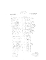
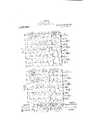
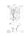
- Figure 1 is a perspective view of the change-making machine; Fig. .2 is an enlarged transverse section of the same; Fig. 3 is an inverted plan view of the under side of the casing top carrying the coin slides; Fig. 4 is a plan view of the top of the casing, the coin slides and the keys foroperating the same, the coin slides being in rearmost setting position for making. $1.09 in change including pennies; Fig. 5 1s a similar view of the same with the coi-n slides partly 'returned yafter partly pressing the ejecting key downward; Fig. 6 is a similar view of the same with the coin slides returned to normal position on the completion of the downward movement and return of the ejecting key; Fig.
- Fig. 7 iis a plan View of releasing device for periodically moving the bottom plate along wiltlh t e middle plate ybeing shown in section;
- Fig. 8 is a similar view of the same with the parts in different position;
- Fig. 9 is a plan view of the casing with the keys and key mechanisms and with the top of the casing and the coin slides removed;
- Fig. 10 is a perspective view of the gathering chute for the change;
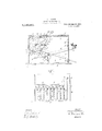
- Fig. 11 is a cross section of the machine on the line 11-1'1 of Fig. 9;
- Fig. 12 is a similar view of the saine with the 25-cent or quarter key for making change including pennies in pressed position;
- FIG. 13 is a similar view of the same with the ejecting key in pressed position for ejecting change of 25 cents including 5 pennies;
- Fig. 14 is a sectional front elevation of the setting keys and the means for locking the ejecting keys against movement while pressing one of the setting keys;
- Fig. 15 is a sectional front elevation of the coin magazines, coin slides and their guideways;
- Fig. 16 is a transverse section of the penny slide in normal position;
- Fig. 17 is-a similar view of the same in position when delivering three pennies;
- Fig. 18 is a like view of the same when delivering two pennies;
- Figs. 19, 20 and 21 are perspective views of the three members constituting the penny slide;
- Fig. 22 is a plan view of the coin slide setting levers; and
- Figs. 23 and 24 are cross sections, showing more particularly the stopping devices for the dime and nickel actuating slides.
- the casing A of the change-making machine is preferably mounted on a suitably constructed base B provided with Aa change- Yreceiving tray or chute B flanked by drawei's B2 for containing tools or other articles.
- a series of coin magazines C, C', C2, C3, and C4 preferably in the form of glass tubes of a size for containing stacks of ycoins such as half dollars, quarter dollars, dimes, nickels and pennies, respectively, it being understood, however, that in machines used in countries havin a money standard dierent from that o the United States it is necessary to change the size of the coin magazines to suit the different coin denominations, such as marks, pfennigs, francs, centimes, shillings, pence and farthings.
- the coins are filled into the coin maga-- zines C, C', C2, C3 and C* at their upper open ends, but, if desired, the coins may be fed into the upper ends of the coin magazines by the use of spurious coin detectors D attached to a plate D hinged to an apertuied support F. through which extend the upper ends of the coin magazines C, C', C2, C3 and C4.
- the support lt) is held on posts E erected on the cover A of the casing A.
- Each spurious coin detector l) if; preferably in the form of an angular' chute havingr an opening of a size correspomliug to the respective coin, and the bottom of the forward angular porticn of each chute is provided with a slot somewhat narrower than the opening of the chute, so that a com which is not of tht ⁇ proper thickness and which is introduced into the detector D drops out of the slut and does not pass into the upper open end of the coin magazine C, C, C,2 (13 or By the arrangement described the coin magazines are filled with coins of the. proper thickness to prevent making wrong change by moving more coins out from ander a coin magazine than should be moved.
- the rearward movement of the coin slides F, (l, Il, I and J is ccntrolled by a seriesl of setting levers K, K, K2, K3 and K4, and the rearward movement of the coin slides F, (l, II and I is also controlled by a second set of keys L, L, L2 and L3, and the return or foi-ard movement of the coin 5 es F, (l, H, I and J is controlled by, an eje-@ting lever N.
- the several keys K, K, K2, K3 and K, L, L, L2 and L2', and N project beyond the .front face of the casing A so as to readily be under the control of the cashier orother person making the change.
- the outer ends of the setting keys K, K, K2, K" and L, L, L2, L, are provided with nger pieces ⁇ having corresponding coin values arranged thereon, as plainly c indicated in Fig. l, that is, the keys K and L are marked $51.00, the keys K, L are marked 50 cents, and the keys K2, L2 are marked 25 cents, the keys K3 and L3 are marked 10 cents, and the key K4 is marked 5 cents, thus indicating that whate ⁇ er key is pressed the legend thereon indi- Cates the amount of change to be made.
- the coin slides F, (i, II, I and J during their forward movement push the lowermost coins in the coin magazines out of the same and into the openings A3 formed in the plate A2, the pushed-out coins dropping into a gathering chute.
- the keys are connected with the coin slides F, (l, Il, I and J in such a manner that ⁇ when the $1.00 key K is pressed all the slides F, G, II, I and J are set for making Ithe operator pressing change of one dollar in 1 half-dollar, 1 quarter-dollar, 1 dilne, 2 nickels and 5 pennies, and when the $1.00 key L is pressed the slides F,( ⁇ ,II andI are set for making change for one dollarin l half-dollar, 1 quarter-dollar, 2 dimes and 1 nickel,
- the coin slides (lr, H, I and J are set for making mln-inge for 50 cents in 1 quarter-dollar, 1 dime, 2 nickels and 5 pennies
- the 50 cents key L is pressed the coin slides (l, Il and I are set for making change for 50 cents in 1 quarter-dollar, 2 dimes and 1 nickel.
- the 25 cents key K2 is pressed the coin slides Il, I and J are set for making change for 25 cents in 1 dime, 2 nickels and 5 pennies, and when the cents key L2 is pressed the coin slides ll and I are set for making change for 25 cents in 2 dimes and 1 nickel.
- the 10 cents key K3 is pressed the coin slides I and J are set for making change for l0 cents in 1 nickel and 5 pennies, and when the 10 cents key L3 is pressed the coin slide I is set for making change for 10 cents in 2 nickels.
- IVhen the 5 cents key K4 is pressed the coin slide J is set for making change in Ii pennies.
- the set coin slides are moved forward on the ejeeting key N, and during this return movement the set coin slides deliver the correct change.
- the pressing and releasing of a setting key and the'ipressing and. releasing of the ejecting key N constitutes a completel operation.
- the coin slide F delivers at each operation thereof a half-dollar, and the coin slide Gr a quarter-dollar.
- the coin slide H delivers at each operation a single dime when the ljeys K, K and K2 are used for setting purposes, and 2 dimes when the keys L, L and L2 are used foli' setting purposes.
- the coin slide I delivers atA each operation a single nickel when the keys L, L, L2 and K3 are used for setting purposes, and 2 nickels when the keys K, K, K2 and L3 are used for setting purposes.
- the coin slide Jdelivers at each operation first 3 pennies and then 2 pennies when either of the keys K, K, K2, K3 or K1 is used for setting purposes.
- the keys K, K, K2, K3, K4, L, L, L2 and L3 are mounted to swing on a rod A (see Figs. 2, 11, 12 and 13) attached to the sides of the casing A, and each of the said keys is pressed on by a spring L4 to normally hold the keys in uppermost position and to return the said keys to uppermost position after being pressed on and released.
- the forward portions of ,the keys K, K, K2, K3, K", L, L, L2, L3 and N extend through slots A in front of the casing A to guide the keys and to limit their up and down motion.
- the keys K, K, K2, K3 and K4 are connected by links O with levers P, P', P2, P3,
- the links O are provided at their lower ends with slots O2 engaged by pins ⁇ 0' on the keys K, K, K2, K2 and K4 to allow return movement of the ke s independent of the links O.
- the keys L, J', L2 and L2 are similarly connected by links Oa with levers Q, Q, Q2, Q2, and Q4 fulcrumed on a rod AB attached to the sides of the casing A, and the said levers are' adapted to engage lugs F2, G2, H2, I3, I* fixed or formed on the under sides of the coin slides F, G, H and I on pressing the corresponding keys.
- the levers Q2 Q3 are rigidly connected with each other and always operate in unison, it being understood that the lever Q2 operates the coin slide H for setting the saine for the ejection of 2 dimes, while the lever Q2 is adapted to set the coin slide I for the ejection of l nickel, and the lever Q* sets the coin slide I l'or the ejection of 2 nickels.
- the levers P, P', P2 P, P, P5, Q, Q', Q2 Q", and Q4 are in the form of bell crank levers so that on pressing the keys K, K', K2, K2, K", L, L', L2 and L3 a rearward swinging motion is given to the long upwardlyextending members of the said bell crank levers by the action of the links (Y) and ()3 connecting the keys 'with the short down- 2 wardly-extending members of the said bell crank levers.
- Each lever P, P', P2 P2, and P2 is provided ⁇ vith an arm P (see Fig. 212) carrying a pin P7 engaging the top oi' :in arm l" held on the next following lever so that when the lever l is actuated it imparts a like motion to the next following lever ll which in turn carries along the lever l2 P2, and the latter carries along the lever P.r and this lever l" carries along the lever l
- the key lv7 is pressed the several coin slides F, (i, ll, l aud .l are moved simultaneously rearward into set position, and when the key K is pressed and the lever P is actuated then the levers P2 P2, l"1 and P5 move with it in unison to rnove the slides G.
- Each of the levers Q and Q' is provided with an arm Q5 having a pin Q engaging the under side of the next following lever Q2 Q2, so that when the lever Q is actuated it imparts a like motion tothe next following lever Q' which in turn carries along the levers Q2 Q2 rigidly connected with each other, aslpijeviously mentioned.
- the lever Q is actuated i and with ⁇ it the lever Q2 Q2 to move the slides (ir, Il and I.
- the key L2 is pressed the two connected levers Q2 ([2 are simultaneously actuated to move the coin slides H and lY simultaneously rearward into set position.
- the lugs on the coin slides and the positions and throws of the levers are arranged relatively to each other so that the coin slides F, (i and l move all thi,l Way bark when the corresponding keys are pressedt
- the dime coin slide ll moves all the way back when, the kevs li. L', L2 are [messed for setting: the coin slide for the electing of two dimes at each operation. and the coin :slide ll moves only half way hack when the keys K, K, K2 arc preffescd for setting the said coin slide io: the ejection of a single dime at one operation.
- the nickel coin slide l moves half way haci; when the 'ieys L.
- Each of the keys K, K, K2, K2, K, L, L', L2 and L2 must be pressed downward to its full extent before the pressed key can return to upper normal position, and for this purpose the following arrangement is made:
- the rear end of the keys K, K', K2, K3 and K4 are provided with hooks vK", and
- hooks L5 are formed on the rear ends of the keys L, L', L2 and L, and the said hooks K and L are adapted to engage a. longitudinally-extending rod S held on arms S secured to a shaft S2 mounted to turn in suitable bearings arranged in the sides of the casing A.
- a spring S3 is connected with one. end of the casing A and at its other end to one of the arms S to normally hold the rod S in lowermost position, that is, on top of the levers K, K', K, K, K, L, L', L2, L immediately in front of the hooks Kxs and L5.
- a segniental ratchet S* to be engaged by a pawl T fulcrumed on a bracket T attached to the right-hand side of ⁇ the casing A.
- the pawl T is provided with a V-shaped heel T2 adapted to be engaged on either face by a V-shaped head T3 on the free end of a flat spring 'l ⁇ 4 secured to the right-hand side of the casing A.
- the head 'l"' is adapted to hold the pawl T in either of the two positions shown in Figs. ll and 12.
- the lower end of the pawl T is adapted to be engaged by a hook-shaped cam S formed on the lower end of the segmental ratchet S to.
- the lon er end of the pawl T is provided with a sidewise extending ⁇ pin T5 adapted to he engaged by a cam N* formed on the rear end ot the ejecting.r lever N to swing the pa wl T from theI position shown in Fig. 12 into the position shown in Fig. 11 when pressing: the ejecting lever N downward so that the ratchet S is unlocked.
- the action of the cam S it is necessary that the ratrhet. S* is swung upward during the. downward movement of the ejecting key N. and after the ratchet S* has been unlocked by the pa wl T.
- the rear end ot the electing lever N is provided with a fork N"l adapted to engage the ratchet S at the time the latter is in lowermost position in front ot' the hooks Ki' and L5 (see Fig. 2). and when the ejecting lever is pressed the ratchet S* is tirst unlocked by inging the pawl 'l ⁇ into unlocking position the action ot' the earn N4.
- the coin slides l" and (i are formed of single llatplates provided near their forward ends with openings F4, G" for the re.- reption oll a halt-dollar and a (marrer-dollar, respective-ly, at the time the said slides F and G are moved rearwardly, and the said openings F4, Gr4 move into register with the corresponding coin magazines C and C.
- the coin slides F and G are of a thickness corresponding to that of half-dollars and quarter-dollars so that only the lowermost coin of a corresponding stack of coins is accommodated aty a time, that is, drops into the opening at the time the latter is in register with the coin magazine.
- the coin passing into the opening F4 or G rests on the plate A2, and on the forward movement lof the coin slide F or G such coin is carried forward over the plate Auntil it drops through the opening A2 into the chute A.
- the dime coin slide H consists of two flat plates H4 and H5 (see Figs. 4, 5 and 6) of which the plate H4 is provided at the front end with an opening HG adapted to register with the coin magazine C2 at the time the coin slide H is moved all the way back into rearmost position.
- the plate H4 is further provided in the rear of the opening H6 with an opening II7 into which fits the plate H5 to slide independently of the plate H4.
- the forward edge of the plate Hf is a distance from the forward wall of the opening H7 so as to form an opening or a pocket for the reception of a dime from the coin magazine C2 at the time the coin slide II is moved half way back, the said pocket then registering with the coin magazine C2 whereby only l dirne is moved forward on the subsequent return or forward motion of the coin slide H.
- the plate Il5 is provided with the lug Il adapted to be engaged by the lever P for moving the coin slide Il half way back as previouslyv mentioned
- the plate H* is provided with the lug H2 adapted to be engaged by the lever Q2 for moving the coin slide ll all the way back for setting the coin slide ll so that on the forward movement thereof a dime is carried along in the opening ll and a second dime is subsequently e r-arried along in the forward end of the )pening il?, the second dime being pushed along by the plate ll".
- the rear end of the plattl Il" is provided with the lugH3 adapted to be engaged by the leve'r R2 for pushing the foin slide il forward.
- the lug llq (sce Figs. 3 and 13) is -irovidcd with a )in ll extendin sidcwise l l and adapted to abut against a shoul er H formed in an arm IlO fulerumed on the plate .V ⁇ .'' and pressed on by a spring Il,
- the springprcssed arm H1 is adapted to be engaged by pin Q7 on the lever Q2 to swing the arm H1 downward to allow the coin f slide plate H4 to slide all the way back when the keys L, L and L2 are pressed.
- the nickel slide I is similar in construction to the dime slide H and consists of two plates I6, IT, of which the plate I is provided at its forward end with an opening Ia adapted to register with the coin magazine C3 at the time the coin slide I is moved all the way back into rearmost position.
- the plate I6 is further provided in the rear ot' the opening I8 with an opening I into which fits the plate I1 to slide independently of the plate I6.
- the forward edge of the plate I7 is a distance from the forward wall of the o ening I9 to form an opening or a pocket or the reception of a nickel from the coin magazine C3 at the time the coin slide I is moved half way back, the said pocket then registering with the coin magazine C3 whereby only 1 nickel is moved forward on the subsequent return or forward movement of the coin slide I.
- the plate I6 is provided with the lugs I', I3, I5 previously mentioned.
- the lug I is adapted to be engaged by the lever P3 for moving the coin slide I all the way back, as shown in Fig. 4.
- the lug I2 is adapted to be engaged by the lever P* for moving the coin slide I half way back.
- the lng I* is adapted to be engaged by the lever Q3 for moving the coin slide I the remaining half way back, and the lug I3 is adapted to be engaged by the lever Q* for moving the coin slide I all the way back when the key L3 is pressed.
- the lug Ir (see Figs. 3 and 24) is provided with a sidewise-extending pin Il adapted to abut 'against a shoulder I formed on an arm I12 secured on a pivot Ila mounted to turn on the plate A2.
- the pivot I13 is provided with an arm I14 extending forwardly under the.
- the ariu Il2 is adapted to he engaged hy a pin Q" on an arm Q9 forming part of the lever Q* so that when the latter swings rearward the aitn 11i-is swung downward against the tension ol' the spring "5 to allow the pin Il" to pass the shoulder t" so that the plate I" can pass into extreme rearinost position at thc time the lever L3 ia pressed.
- the arm Im is adapted to he engaged hy a pin P held 0n an arm l"" formingr parts ot' the levers P2 P" so that when the levers l" l ai'e aetnated the pin P" swings the arm I" downward and with it the arin 1Z to allow the pin 0 to paas the shoulder l2 at the time the keys K, l and K2 are preSSed.
- rl ⁇ lie middle plate J' is provided with tll two lugs ⁇ J and J2 previously' mentioned, i of which the linei J is adapted to he engaged by the lever l while the lug J2 is adapted to he engaged yh v the lever R4 for moving the slide J loaehY into forward position.
- An opening V is arranged in the plate J4 in the rear ol the opening J" and this openingr is adapted to he elosed at. the bottom hy the forward eIid of the. p'ate J".y so that the openingr J7 is of a depth to accommodate two penniea. as indicated iii Fig. t7. at the time the opening J7 ie in ret'iffter with the eoin magazine t.” and at the time the eoii slide J has been i.ioved hall' wav haelt.
- 'llie bottom plate J5 (see Fig, 21) is provided with slotsy J, JJ for the passage ot' the luge,y .Vt J ⁇ and the Said slots are separated li :i cross hatl Jm adapted to lie engaged hy the Said lugs J', J2 ot the middle plate J4 for periodically carrying;r the plate J along, as hereinafter more fully explained.
- the liottoni of the ir'te J is Somewhat narrower than the mid- , ⁇ late J" and the latter is provided at the under side with guideways J1 (see Figs. 7, 8 and 20) for the plate J5 to Slide in.
- the rear end of the lever li ia preaaed outward h v a spring Uf ecui'ed or t'orined en the i'car end ot the plate J"7 so a to ving ther pawl li into eli- ;ragenient with the yahoulder J-.
- top plate J3 is provided at its righthand side with a stoplug Jis extendirrt.r into thc notch to limit the rearward and forward sliding movement of the said top plate.
- the arm W on the right-hand side is provided with an extension Vl having an .inclined top lV adapted to pass under the ejecting lever
- the arms lV are provided with cxtcnsions Vl extending between adjacent setting keys with the exception of the arm W on the right end, the extension VV of which is provided with an inclined top W5 adapted to pass under the ejecting key N.
- ⁇ The npper ends of the extensions WU are guided in a guide har' W" attached to the rear face ot. the front of the casing, and the right-hand end of the said guide bar W form s a stop for the extension W4 of the right-'hand arm lV.
- YVlien a key K, K', K2, K3, K, L, L', L2 or L is pressed, the corresponding arms to the right of the key are swung to the right so that the arm lV having the extension W4 swings under the ejccting; lever N to prevent the same from being,r actuated, during,r the time one of the other keys is actuated.
- the prescrit setting key passes between adjacent. arms YW all the arms are held against urtlnlr .movement and hence the remaining non setting:y keys as well as the eject ing hey are locked against downward movenient.
- the operator now swings the rjecting key N downward so as to actual the several levers R, R', R2, R3 and R* to rc-turi the set coin slides to forward position, and in doingr so to cause the actuated coin slider; to push the coins out from under the coin mfgazincs in thel manner above dcscribedA l'i'licn it.
- ing lever is swun downward to cause the corresponding sli es to be pushed forward with a view to remove the corresponding coins from under the coin magazines.
- the operator next presses the ejecting lever N downward so that the several coin slides F, G, H, I and J are returned to normal position whereby the coin slide F moves 1 half-dollar from under the stack ot' coins in the coin magazine C, the slide G moves l quarter-dollar from under the stack of coins in the coin ma azine C', the coin slide H moves a single une from under the stack of coins in the coin magazine C", while the coin slide 1 moves successively 2 nickels from under the stack of nickels in the coin magazine C and the coin slide J moves successively three pennies and two pennies from under the stack of pennies contained in the coin magazine C4.
- the operator presses the setting .key K so that the coin slides G, I and J are moved all the way back into setting position while the coin slide H is moved half way back, and then the operator presses the ejectinfy lever N so as io return the coin slides i, II, I and .I to normal forward position whereby the coin slide (i ejects a quarter-dollar from under the stark of coins in the. coin )Hagar/.ine the coin #lille ll cjects l dime, the coin slide I @jects 2 nickels and the coin slide J ejeets 5 pennies in the same manner as above explained relative to the pressing of the kev li.
- the, ⁇ operator presses the key L so that the slides l", G and move all the way back while the slide I is moved half way back, and then the opera-- tor presses the ejecting key N to return the coin slides F, G, H and I into forward position whereby the coin slide I" ejects a halfdollar, the coin slide (l cjects 1 quarter-dollar, the coin slide Il ejects 2 dimef ⁇ and the coin slide I ejects 1 nickel.
- the o ierator presses the setting key L whereby tile slides G and H are moved all the wa back while the coin slide I is moved hal way back, and then the operator presses the ejecting lever N to return the coin slides G, H and I to normal forward position, whereby the coin slide G ejects 1 quarter dollar, the slide H ejvects 2 dimes and the coin slide I ejects 1 nickel.
- the operator presses the setting ke L2 whereby the coin slide H is moved all t e way back and the coin slide I half wey back, and then the operator presses the electing key N to return the said coin slides AI and I to forward position whereby the coin slide H ejects 2 dimes and the coin slide I cjects 1 nickel.
- the operator presses the ejecting ey L a to move the slide I all the way back, and then the operator presses the. ejcciiing key N to return the coin slide l to forward position, and in doing so the coin slide l ejects 2 nickels.
- l. li a elninge-nlzikinfg machine.
- a coin magazine adapted to 'ontain a :stark of coins.
- :i coin slide movable under the said ein magazine and having two openings :nl apied to nove successively into register with the said Coin nnigazinr.
- a coin magazine adapted to contain a .seck of roins., a coin slide movable Under the said Isoin magst/.ine and havin two openings adapted to more slccersrmy into register with the said coin magazine, the said coin slide being formed of two plates of which one is provided with two openings one in front of the other, the rear opening con taining the other' plate, setting keys connected with the coin slide to move the lat- 'ter in one direction until either opening is in register with the said coin magazine, and ejecting means connected with the coin slide for moving the latter in a reverse direction from either of the set positions to remove either one or two coins from under the stack of coins.
- a coin magazine adapted to contain a stack of pennics, a coin slide movable under the stack of pennies and consisting of a plurality of superimposed plates, of which the middle plate is provided with openings arranged one in front of the other and adapted to move into register with the said coin magazine for receiving each a plurality of pennies, the bottom plate being adapted to close the rear opening and the top plate forming a cut-olf for the pennies in the coin magazine, and means for moving the said plates.
- a coin magazine adapted to contain a stack of coins
- a coin slide movable under the said coin magazine and having two openings adapted to move successively into register with the said coin magazine.
- the said coin slide being formed of two plates, of which one is provided with two openings one in front of the other, the rear opening containing the other plate, setting keys connected with the said coin slide, one of the keys being adapted to move the said coin slide in one direction into set position with the rear opening in register with the said coin' magazine, and the other key for moving the coin slide in the same direction into set position with the front opening in registerr with the said coin magazine, and an eject ing key connected with the said coin slide for moving the latter in a reverse direction from either of the said sct positions to remove one or two coins from under the stack of coins.
- a coin magazine adapted to contain a stack of coins
- a coin slide movable under the said coin magazine and having two openings adapted to move successively into register with the said coin magazine
- the said coin slide being formed of two plates, of which one is provided with two openings, one in front of vthe other, the rear opening containing the other plate, setting keys connected with the said coin slide, one of the kevs being adapted to move the said coin slide in one direction into set position with the rear opening in register with the said coin magazine, and the other key for moving the coin slide in the same direction into set position with the front opening in register with the said coin magazine, an ejecting key connected with the said coin slide for moving the latter in a reverse direction from either of the set positions to remove one or two coins from under the stack of coins, and means for limiting the sliding movement of the coin slide into set position.
- a coin magazine adapted to contain a stack of pennies, a coin slide movable under the said stack of coins and consisting of three super* imposed plates, of which the middle plate is provided with openings arranged one in front of the other and adapted to move into register with the said coin magazine for receiving each a plurality of pennies, means for imparting movement to the middle plate, and means for periodically moving the top and bottom plates along with the said midd le plate.
- a change-making machine a coin magazine adapted to contain a stack of pennies, a coin slidemovable under the said stack of coins and consisting of three superimposed plates, of which the middle plate is provided with openings arranged one in front of the other and adapted to move into register with the said coin magazine for receiving each a plurality of pennies, and the said bottom plate is adapted to move under the rear opening of the said middle plate to close the rear opening below the said coin magazine, and the top plate is adapted to move under the coin magazine to form a cut-,oil for the coins in the coin magazine, means for imparting movement to the said middle plate, and means for periodically moving the top and bottom plates along with the said middle plate.
- a coin magazine adapted to contain a stack of pennies, a coin slide movable under the said stack of coins, and consisting of three superimposed plates, of which the middle plate is provided with openings arranged one in front of the other and adapted to move into register with the said coin magazine for receiving each a plurality of pennies, a set ting key connected with the said middle plate for moving the said coin slide rearwardly into set position, an ejecting key connected with the said middle plate for moving the coin slide forward into ejecting position, and means connecting the said middle plate with the said top and bottom plates for moving thc latterr periodically along with the said middle-plate.
- a coin magazine adapted to contain a stack of pennies, a coin slide movable under the said stack oll coins and consisting of three superimposed plates, of which the middle plate is provided with openings arranged one in front of the other and adapted to move into register with the said coin magazine for re celving each a pluralitv of pennies, a setting key connected with the said middle plate for moving the said coin slide rear vvardly into set position7 an ejecting key connected with the said middle plate for moving the coin slide forward into ejecting position, nieans connecting the said middle plate with the said top and bottom plates tor moving the latter periodi -ally along with the said middle plate, and means for limiting the sliding movement of the said top and bottom plates.
- a change-making machine a coin. magazine adapted to contain a stack of pennies, a coin slide movable under the said stack of coins and consisting of three superimposed plates.
- the middle plate is provided with openings arranged one in front ol the other and adapted to move into register' with the said coin magazine for receiving each a plurality of pennies
- the said bottom plate is adapted to lnove nnder the rear opening of the said middle plate to close the, rear opening below the said coin magazine
- the top plate is adapted to move under the coin magazine to form a cut ofi' for the coins in the coin magazine, spaced lugs on the said middle plate, levers, adapted to engage the said lugs, a setting key conneeted with one of the said levers,y for movingr the middle plate of the coin slide into set position, an ejecting key connected with the other lever for moving the middle plate of the coin slide into ejecting position, and means connecting the said middle plate with the said top and bottom
- a change-making machine a series of coin magazines adapted to contain stacks of coins of different denominations, a series ot' coin slides operating under the said magazines for removing the lowermost coins from under the stacks of coins, a series of setting keys, a series of actuating levers adapted to engage the lsaid coin slides to move the same rearward into setting positionr ⁇ links connecting the said setting keys with the said actuating levers, means adapted to connect the said actuating kevs with each other.
Landscapes
- Physics & Mathematics (AREA)
- General Physics & Mathematics (AREA)
- Control Of Vending Devices And Auxiliary Devices For Vending Devices (AREA)
Description
C. HQFMANN CHANGE MAKN? APPUCANON mm MAY 21,
Mmmm.
'NHA
Pimps-med Apr. 2G, 1915.
WUNESSE'S G. HOFMANN. CHANGE MAKING MACHINE.
1 mvENroR G. HUFMANN.
CHANGE MAKING MACHINE.
APPLICAUON min MAY 21. 191s.
Patentedpr. zu, 191.5.
8 SHEETS-SHEET i.
N VEN T0 R @go/ye fio/mann WITNESSES /MM.
@fm/@ &1
- manners G. HOFMANN.
CHANGE MAKING MACHINE.
APPLICATION FILED MAY2\,1913.
Patented A111220, 1915.
8 SHEETS SHEET 6.
.NTOHNEVS G. HOFMANN.
CHANGE MAKING MACHINE.
AWLICATWN man MAY 21 ma.
Patented Apr. 20, 1915.
8 SEEBTSSHBBT B.
N VEN T0" @9a/ye fifa/72760727 ATTORNEYS the locking and Ythe'middle plate of the penny coin slide,
UniTED STATES PATENT OFFICE,
GEORGE HOFMANN, 0F LYONS, IOWA, .ASSIGNOR OF ONE-HALF TO ROBERT HOLDING, 0F LYONS, IOWA.
Speccation of Letters Patent.
CHANGE-MAKING MACHINE.
Patented Apr. 20, 1915.
To all whom itmay concern Be it known that I, GEORGE HOFMANN, a citizen of the United States, and a resident of Lyons, in the county of Clinton and State of Iowa, have invented a new and Improved Change-Making Machine, of which the following is a full, clear, and exact description.
The invention relates to change-making machines having tubes for containing coins of different denominations, and means for delivering the coins from one or more tubes by means of keys.
The object of the invention is to provide a new and improved change-making machine for use by cashiers and other persons for quickly7 and accurately making change either with or without pennies.
In order to accomplish the desired result use is made of a series of coin magazines for containing stacks of coins of different denominations, coin slides for receiving the lowermost coins from the said stacks of coins, one or two sets of setting keys for setting the said coin slides according to the change to be made, and an ejecting key for moving the set coin slides to eject coins from under the stack of coins.
A practical embodiment of the invention is represented rin the accompanying drawings foi'ming a part of this specification, in which similar characters of reference indidate corresponding parts in all the views.
Figure 1 is a perspective view of the change-making machine; Fig. .2 is an enlarged transverse section of the same; Fig. 3 is an inverted plan view of the under side of the casing top carrying the coin slides; Fig. 4 is a plan view of the top of the casing, the coin slides and the keys foroperating the same, the coin slides being in rearmost setting position for making. $1.09 in change including pennies; Fig. 5 1s a similar view of the same with the coi-n slides partly 'returned yafter partly pressing the ejecting key downward; Fig. 6 is a similar view of the same with the coin slides returned to normal position on the completion of the downward movement and return of the ejecting key; Fig. 7 iis a plan View of releasing device for periodically moving the bottom plate along wiltlh t e middle plate ybeing shown in section; Fig. 8 is a similar view of the same with the parts in different position; Fig. 9 is a plan view of the casing with the keys and key mechanisms and with the top of the casing and the coin slides removed; Fig. 10 is a perspective view of the gathering chute for the change; Fig. 11 is a cross section of the machine on the line 11-1'1 of Fig. 9; Fig. 12 is a similar view of the saine with the 25-cent or quarter key for making change including pennies in pressed position; Fig. 13 is a similar view of the same with the ejecting key in pressed position for ejecting change of 25 cents including 5 pennies; Fig. 14 is a sectional front elevation of the setting keys and the means for locking the ejecting keys against movement while pressing one of the setting keys; Fig. 15 is a sectional front elevation of the coin magazines, coin slides and their guideways; Fig. 16 is a transverse section of the penny slide in normal position; Fig. 17 is-a similar view of the same in position when delivering three pennies; Fig. 18 is a like view of the same when delivering two pennies; Figs. 19, 20 and 21 are perspective views of the three members constituting the penny slide; Fig. 22 is a plan view of the coin slide setting levers; and Figs. 23 and 24: are cross sections, showing more particularly the stopping devices for the dime and nickel actuating slides.
The casing A of the change-making machine is preferably mounted on a suitably constructed base B provided with Aa change- Yreceiving tray or chute B flanked by drawei's B2 for containing tools or other articles. On top of the casing A is arranged a series of coin magazines C, C', C2, C3, and C4, preferably in the form of glass tubes of a size for containing stacks of ycoins such as half dollars, quarter dollars, dimes, nickels and pennies, respectively, it being understood, however, that in machines used in countries havin a money standard dierent from that o the United States it is necessary to change the size of the coin magazines to suit the different coin denominations, such as marks, pfennigs, francs, centimes, shillings, pence and farthings.
The coins are filled into the coin maga-- zines C, C', C2, C3 and C* at their upper open ends, but, if desired, the coins may be fed into the upper ends of the coin magazines by the use of spurious coin detectors D attached to a plate D hinged to an apertuied support F. through which extend the upper ends of the coin magazines C, C', C2, C3 and C4. The support lt) is held on posts E erected on the cover A of the casing A. Each spurious coin detector l) if; preferably in the form of an angular' chute havingr an opening of a size correspomliug to the respective coin, and the bottom of the forward angular porticn of each chute is provided with a slot somewhat narrower than the opening of the chute, so that a com which is not of tht` proper thickness and which is introduced into the detector D drops out of the slut and does not pass into the upper open end of the coin magazine C, C, C,2 (13 or By the arrangement described the coin magazines are filled with coins of the. proper thickness to prevent making wrong change by moving more coins out from ander a coin magazine than should be moved.
Directly under the cover A and the coin magazines C, (l, C2, C3 and C* are arranged coin slides F, (l, H, I and J mounted to slide transversely in suitable guidcwavs arranged on a plate A2 attached to the casing A at the top thereof directly under the cover A. The rearward movement of the coin slides F, (l, Il, I and J is ccntrolled by a seriesl of setting levers K, K, K2, K3 and K4, and the rearward movement of the coin slides F, (l, II and I is also controlled by a second set of keys L, L, L2 and L3, and the return or foi-ard movement of the coin 5 es F, (l, H, I and J is controlled by, an eje-@ting lever N. The several keys K, K, K2, K3 and K, L, L, L2 and L2', and N project beyond the .front face of the casing A so as to readily be under the control of the cashier orother person making the change.
The outer ends of the setting keys K, K, K2, K" and L, L, L2, L, are provided with nger pieces` having corresponding coin values arranged thereon, as plainly c indicated in Fig. l, that is, the keys K and L are marked $51.00, the keys K, L are marked 50 cents, and the keys K2, L2 are marked 25 cents, the keys K3 and L3 are marked 10 cents, and the key K4 is marked 5 cents, thus indicating that whate\er key is pressed the legend thereon indi- Cates the amount of change to be made.
The coin slides F, (i, II, I and J during their forward movement push the lowermost coins in the coin magazines out of the same and into the openings A3 formed in the plate A2, the pushed-out coins dropping into a gathering chute. A" secured to thel under side of the plate A2 and leading to the coin-receiving tray B projecting at the front of the base l to permit the convenient removal of the change.
The keys are connected with the coin slides F, (l, Il, I and J in such a manner that `when the $1.00 key K is pressed all the slides F, G, II, I and J are set for making Ithe operator pressing change of one dollar in 1 half-dollar, 1 quarter-dollar, 1 dilne, 2 nickels and 5 pennies, and when the $1.00 key L is pressed the slides F,(},II andI are set for making change for one dollarin l half-dollar, 1 quarter-dollar, 2 dimes and 1 nickel, When the 50 cents key K is pressed, the coin slides (lr, H, I and J are set for making mln-inge for 50 cents in 1 quarter-dollar, 1 dime, 2 nickels and 5 pennies, and when the 50 cents key L is pressed the coin slides (l, Il and I are set for making change for 50 cents in 1 quarter-dollar, 2 dimes and 1 nickel. lVhen the 25 cents key K2 is pressed the coin slides Il, I and J are set for making change for 25 cents in 1 dime, 2 nickels and 5 pennies, and when the cents key L2 is pressed the coin slides ll and I are set for making change for 25 cents in 2 dimes and 1 nickel. When the 10 cents key K3 is pressed the coin slides I and J are set for making change for l0 cents in 1 nickel and 5 pennies, and when the 10 cents key L3 is pressed the coin slide I is set for making change for 10 cents in 2 nickels. IVhen the 5 cents key K4 is pressed the coin slide J is set for making change in Ii pennies.
The set coin slides are moved forward on the ejeeting key N, and during this return movement the set coin slides deliver the correct change. Thus the pressing and releasing of a setting key and the'ipressing and. releasing of the ejecting key N constitutes a completel operation. The coin slide F delivers at each operation thereof a half-dollar, and the coin slide Gr a quarter-dollar. The coin slide H delivers at each operation a single dime when the ljeys K, K and K2 are used for setting purposes, and 2 dimes when the keys L, L and L2 are used foli' setting purposes. The coin slide I delivers atA each operation a single nickel when the keys L, L, L2 and K3 are used for setting purposes, and 2 nickels when the keys K, K, K2 and L3 are used for setting purposes. The coin slide Jdelivers at each operation first 3 pennies and then 2 pennies when either of the keys K, K, K2, K3 or K1 is used for setting purposes.
The keys K, K, K2, K3, K4, L, L, L2 and L3 are mounted to swing on a rod A (see Figs. 2, 11, 12 and 13) attached to the sides of the casing A, and each of the said keys is pressed on by a spring L4 to normally hold the keys in uppermost position and to return the said keys to uppermost position after being pressed on and released. The forward portions of ,the keys K, K, K2, K3, K", L, L, L2, L3 and N extend through slots A in front of the casing A to guide the keys and to limit their up and down motion.
The keys K, K, K2, K3 and K4 are connected by links O with levers P, P', P2, P3,
P4 and P5 mounted to swing on a rod A2' massoni attached to the sides of the casing A, and the said levers are adapted to engage lugs F', G', H', I', I2, and J fixed on the under sides of the coin slides F, G, H, I and J, respectively, to impart a rearward sliding motion to the said coin slides on pressing the keys. The links O are provided at their lower ends with slots O2 engaged by pins` 0' on the keys K, K, K2, K2 and K4 to allow return movement of the ke s independent of the links O. The keys L, J', L2 and L2 are similarly connected by links Oa with levers Q, Q, Q2, Q2, and Q4 fulcrumed on a rod AB attached to the sides of the casing A, and the said levers are' adapted to engage lugs F2, G2, H2, I3, I* fixed or formed on the under sides of the coin slides F, G, H and I on pressing the corresponding keys. The levers Q2 Q3 are rigidly connected with each other and always operate in unison, it being understood that the lever Q2 operates the coin slide H for setting the saine for the ejection of 2 dimes, while the lever Q2 is adapted to set the coin slide I for the ejection of l nickel, and the lever Q* sets the coin slide I l'or the ejection of 2 nickels.
The levers P, P', P2 P, P, P5, Q, Q', Q2 Q", and Q4 are in the form of bell crank levers so that on pressing the keys K, K', K2, K2, K", L, L', L2 and L3 a rearward swinging motion is given to the long upwardlyextending members of the said bell crank levers by the action of the links (Y) and ()3 connecting the keys 'with the short down- 2 wardly-extending members of the said bell crank levers.
Each lever P, P', P2 P2, and P2 is provided `vith an arm P (see Fig. 212) carrying a pin P7 engaging the top oi' :in arm l" held on the next following lever so that when the lever l is actuated it imparts a like motion to the next following lever ll which in turn carries along the lever l2 P2, and the latter carries along the lever P.r and this lever l" carries along the lever l Thus when the key lv7 is pressed the several coin slides F, (i, ll, l aud .l are moved simultaneously rearward into set position, and when the key K is pressed and the lever P is actuated then the levers P2 P2, l"1 and P5 move with it in unison to rnove the slides G. ll, I and l rearward. When the lever K2 is pressed and the lever P2 P2 is actuated then the levers P* and P5 move with it in unison to inove the slides H,I and J rearward. `When the lever K3 is pressed and the lever P4l is actuated then the lever P5 moves with it in unison to move the slides I and J rearward. lit is understood that the levers P2, P4 are close together and aetuate the same coin slide I, and the levers P2 P3 form a double lever and simultaneously aetuate the coin slides H and I.
Each of the levers Q and Q' is provided with an arm Q5 having a pin Q engaging the under side of the next following lever Q2 Q2, so that when the lever Q is actuated it imparts a like motion tothe next following lever Q' which in turn carries along the levers Q2 Q2 rigidly connected with each other, aslpijeviously mentioned. Thus when the key'` is pressed the several coin slides F, (i, and I are moved simultaneously rearward into said position, and when the key L' ispressed the lever Q is actuated i and with` it the lever Q2 Q2 to move the slides (ir, Il and I. When the key L2 is pressed the two connected levers Q2 ([2 are simultaneously actuated to move the coin slides H and lY simultaneously rearward into set position.
The lugs on the coin slides and the positions and throws of the levers are arranged relatively to each other so that the coin slides F, (i and l move all thi,l Way bark when the corresponding keys are pressedt The dime coin slide ll moves all the way back when, the kevs li. L', L2 are [messed for setting: the coin slide for the electing of two dimes at each operation. and the coin :slide ll moves only half way hack when the keys K, K, K2 arc preffescd for setting the said coin slide io: the ejection of a single dime at one operation. The nickel coin slide l moves half way haci; when the 'ieys L. L and lf are pressed i'or set-ting the coin slide l for the ejection of a .single nickel at each opeiatioi'i, and the said slide l moves all the way hack when the keys K, K, K2, K2 and l," are pressed for setting the :foin slide l for the ejection of two nickels at ear-h ol'reration.
The rein slides I7. (di, H, l and d are provided at the under side (see Fig. il)
with lugs l, (i3, il, I" and J2, respectively,
adapted to be engaged by arms R, R R2, R2 and li* secured to a shaft R5, and on` the said shaft It* is secured an arm R ypivotully connected by a link It with an arm N secured on the pivot or shaft N2 of the lever N so that when the lever N is swung downward by the operator the shaft R2 is rocked and the arms R, R', R2, R2 and R* swing forward and engage the lugs F3, G2, H2, I5 and l2 ot' the coin slides in setrpo sition at the time, and push the said set coin slides forward whereby the lowermost coins in the coin magazines, C, C', C2, Cz and C* are removed and carried to the openings A3 to drop through the chute A* into the tray B. The ejecting lever N is returned to normal uppermost position after being pressed and released by the s ring N2.
Each of the keys K, K, K2, K2, K, L, L', L2 and L2 must be pressed downward to its full extent before the pressed key can return to upper normal position, and for this purpose the following arrangement is made: The rear end of the keys K, K', K2, K3 and K4 are provided with hooks vK", and
llt
similar hooks L5 are formed on the rear ends of the keys L, L', L2 and L, and the said hooks K and L are adapted to engage a. longitudinally-extending rod S held on arms S secured to a shaft S2 mounted to turn in suitable bearings arranged in the sides of the casing A. A spring S3 is connected with one. end of the casing A and at its other end to one of the arms S to normally hold the rod S in lowermost position, that is, on top of the levers K, K', K, K, K, L, L', L2, L immediately in front of the hooks Kxs and L5. On the right-hand side of the shaft S2 is secured a segniental ratchet S* to be engaged by a pawl T fulcrumed on a bracket T attached to the right-hand side of` the casing A. The pawl T is provided with a V-shaped heel T2 adapted to be engaged on either face by a V-shaped head T3 on the free end of a flat spring 'l`4 secured to the right-hand side of the casing A. The head 'l"' is adapted to hold the pawl T in either of the two positions shown in Figs. ll and 12. The lower end of the pawl T is adapted to be engaged by a hook-shaped cam S formed on the lower end of the segmental ratchet S to. throw the pawl T from the position shown in Fig. 1.1 into the position shown in Fig. 12 at the time a key has been pressed. Now when the pressed key is released and returns to its normal uppermost position the ratchet S4 swings downward and the lowermost end of the pawl T now engages the bottom tooth of the ratchet S* at a cut-out or mutilated portion Sb' thus looking the ratchet S, the rod S and the keys against upward swinging movement.
The lon er end of the pawl T is provided with a sidewise extending` pin T5 adapted to he engaged by a cam N* formed on the rear end ot the ejecting.r lever N to swing the pa wl T from theI position shown in Fig. 12 into the position shown in Fig. 11 when pressing: the ejecting lever N downward so that the ratchet S is unlocked. In order to return the pawl T to the previous position b r the action of the cam S it is necessary that the ratrhet. S* is swung upward during the. downward movement of the ejecting key N. and after the ratchet S* has been unlocked by the pa wl T. For this purpose the rear end ot the electing lever N is provided with a fork N"l adapted to engage the ratchet S at the time the latter is in lowermost position in front ot' the hooks Ki' and L5 (see Fig. 2). and when the ejecting lever is pressed the ratchet S* is tirst unlocked by inging the pawl 'l` into unlocking position the action ot' the earn N4. as previously exiain'wh and` then the t'ork N5 engages the rod ri and s-wings the ratehet S* upward so that inall): thi` cani Si3 engages the lower end nl' the pawl Viaud swings the same back into lurking position. lt is understood that when adapted the ejecting lever N is in normal position the pin S is free to clear the fork N Whenever one of the setting keys is pressed, as above explained.
When one of the keys K, K', K2, K", K", L, L', L, or L3 is pressed and the ratchet S* is swung upward then the upper end of the pawl T 1s in enga ement with the ratchet S* and glides over he teeth thereof but prevents upward movement of the' pressed key should the latter be released previous to reaching its lower-most position. When the pressed key moves into lowermost position the cam S5 engages the lower end of the pawl T and throws the pawl over to release the ratchet S, thus allowing the pressed key to return to uppermost position and to allow the ratchet S* to swing down to lowermost position. When the ejecting lever N is ressed a similar operation is repeated, that 1s, during the downward movement of the said lever N the upper end of the pawl glides over the ratchet. wheel Si, and should the lever N be stopped prior to reaching the end of its downward stroke the pawl T holds the ratchet S4 against return movement and with it the lever N.
When a setting key has been pressed to the full extent and released and returned to uppei-most position and the ratchet S4 moved down to lower-most position the lower end of the pawi T glides over the ratchet S4 during this downward movement of the ratchet so that the ratchet S4 is locked against movement should another setting key be accidentally pressed by the operator. Now as the ratchet S* is held locked against upward movement the setting keys are locked against downward movement. The lever N when next p i ssed imparts a swinging motion to the pawl T by the cam N to unlock the ratchet S* and to allow the key il to be swung downward.
From the toregoing-it will be seen that either of the keys K, K, K2, K3, K, L, L', L2, L3 and N must be pressed all the way down before the operator is able to return the pressed key to uppermost position owing to the pawl T engaging the ratchet S, and another settingkey cannot subsequently be pressed unless the ejeeting lever N is first actuated to the`full extent. Thus after a setting key is pressed and returned it is not possible to press another setting key, but the operator must actuate the ejecting lever N prior to pressing another setting key. By the arrangement described the operator must aetuate the setting keys and the ejecting key to their full extent and in the proper order to work the machine.
The coin slides l" and (i are formed of single llatplates provided near their forward ends with openings F4, G" for the re.- reption oll a halt-dollar and a (marrer-dollar, respective-ly, at the time the said slides F and G are moved rearwardly, and the said openings F4, Gr4 move into register with the corresponding coin magazines C and C. The coin slides F and G are of a thickness corresponding to that of half-dollars and quarter-dollars so that only the lowermost coin of a corresponding stack of coins is accommodated aty a time, that is, drops into the opening at the time the latter is in register with the coin magazine. The coin passing into the opening F4 or G rests on the plate A2, and on the forward movement lof the coin slide F or G such coin is carried forward over the plate Auntil it drops through the opening A2 into the chute A.
The dime coin slide H consists of two flat plates H4 and H5 (see Figs. 4, 5 and 6) of which the plate H4 is provided at the front end with an opening HG adapted to register with the coin magazine C2 at the time the coin slide H is moved all the way back into rearmost position. The plate H4 is further provided in the rear of the opening H6 with an opening II7 into which fits the plate H5 to slide independently of the plate H4. The forward edge of the plate Hf is a distance from the forward wall of the opening H7 so as to form an opening or a pocket for the reception of a dime from the coin magazine C2 at the time the coin slide II is moved half way back, the said pocket then registering with the coin magazine C2 whereby only l dirne is moved forward on the subsequent return or forward motion of the coin slide H. The plate Il5 is provided with the lug Il adapted to be engaged by the lever P for moving the coin slide Il half way back as previouslyv mentioned, and the plate H* is provided with the lug H2 adapted to be engaged by the lever Q2 for moving the coin slide ll all the way back for setting the coin slide ll so that on the forward movement thereof a dime is carried along in the opening ll and a second dime is subsequently e r-arried along in the forward end of the )pening il?, the second dime being pushed along by the plate ll". The rear end of the plattl Il" is provided with the lugH3 adapted to be engaged by the leve'r R2 for pushing the foin slide il forward. i
in order to limit tht rearward movement ol the plate Il4 at the time the key K, K or l'' pressed, the `following arrangement is iliade: The lug llq (sce Figs. 3 and 13) is -irovidcd with a )in ll extendin sidcwise l l and adapted to abut against a shoul er H formed in an arm IlO fulerumed on the plate .V`\.'' and pressed on by a spring Il, Thus when the arm Ill is in normal position and the plate H4 is moved rearward into halt' wav bark position and the pin 1I abuts agaimt the shoulder Il'J to limit the rearward movement of the plate Il. The springprcssed arm H1 is adapted to be engaged by pin Q7 on the lever Q2 to swing the arm H1 downward to allow the coin f slide plate H4 to slide all the way back when the keys L, L and L2 are pressed.
The nickel slide I is similar in construction to the dime slide H and consists of two plates I6, IT, of which the plate I is provided at its forward end with an opening Ia adapted to register with the coin magazine C3 at the time the coin slide I is moved all the way back into rearmost position. The plate I6 is further provided in the rear ot' the opening I8 with an opening I into which fits the plate I1 to slide independently of the plate I6. The forward edge of the plate I7 is a distance from the forward wall of the o ening I9 to form an opening or a pocket or the reception of a nickel from the coin magazine C3 at the time the coin slide I is moved half way back, the said pocket then registering with the coin magazine C3 whereby only 1 nickel is moved forward on the subsequent return or forward movement of the coin slide I.
The plate I6 is provided with the lugs I', I3, I5 previously mentioned. The lug I is adapted to be engaged by the lever P3 for moving the coin slide I all the way back, as shown in Fig. 4. The lug I2 is adapted to be engaged by the lever P* for moving the coin slide I half way back. The lng I* is adapted to be engaged by the lever Q3 for moving the coin slide I the remaining half way back, and the lug I3 is adapted to be engaged by the lever Q* for moving the coin slide I all the way back when the key L3 is pressed. It is understood that when the coin slide I is moved half way back a nickel passes into the forward end of the opening I to be pushed forward by the plate I1 at the subsequent return oi" forward movement of the coin slide I, and when the coin slide I is all the way back then the opening IB is in re ister with the coin magazine C3, and on the orward movement of the coin slide I this nickel is carried along in the opening IE and a second nickel subsequently passes into the forward end of the opening I to be pushed along by the plate IT so that the two nickels are removed from the stack of nickels and drop through the opening A3 to pass by way of the chute A* to the tray B. It is understood that the lug I5 on the plate I is engaged by the lever R" for moving the coin slide I from set position (either half way back or all the way back) to forward position.
In order to limit the rearward movement of the plate IG at the time the key L, L', L2 or K3 is pressed, the following arrangement is made: The lug Ir (see Figs. 3 and 24) is provided with a sidewise-extending pin Il adapted to abut 'against a shoulder I formed on an arm I12 secured on a pivot Ila mounted to turn on the plate A2. The pivot I13 is provided with an arm I14 extending forwardly under the. plate A, and the arin 1'2 and with it the artn 14 are pressed itpward into normal position hy a Spring 1, The ariu Il2 is adapted to he engaged hy a pin Q" on an arm Q9 forming part of the lever Q* so that when the latter swings rearward the aitn 11i-is swung downward against the tension ol' the spring "5 to allow the pin Il" to pass the shoulder t" so that the plate I" can pass into extreme rearinost position at thc time the lever L3 ia pressed. The arm Imis adapted to he engaged hy a pin P held 0n an arm l"" formingr parts ot' the levers P2 P" so that when the levers l" l ai'e aetnated the pin P" swings the arm I" downward and with it the arin 1Z to allow the pin 0 to paas the shoulder l2 at the time the keys K, l and K2 are preSSed.
The penny coin slide. J eonsietg oth three flat ilates Ji. J2 J5 (Seti Figa 3, .if` i',i 1o, 17r` 18, 19. Q0 and 21) placed one dn top ot' the other so that the p' l5 rests on the plate A2 while the rear portion of' the plate J4 rests on the top et' the plate J and the forwaid portion of the Said plate J rests on the plate A2. The plate J'" is superinipoaed ou the plate J". rl`lie middle plate J' is provided with tll two lugs` J and J2 previously' mentioned, i of which the linei J is adapted to he engaged by the lever l while the lug J2 is adapted to he engaged yh v the lever R4 for moving the slide J loaehY into forward position. The forward end ot the middle plate J" irs provided with an opening il" ol' a depth correspondingi to the aggregate height 0f three superimposed pennieaso anA to ac` eonimodate the three lowerinot pennies in the stark of pennies` contained in the coin magazine C" at the time the opening J is in register with the Said coin iiiagaxine, (i (see Fig. 1(3). ylien the coin slide J in moved forward the three pennies eoiitained in the opening J are earried along;v and drop through the opening;y A` aa indicated iii Fig. 17. An opening V is arranged in the plate J4 in the rear ol the opening J" and this openingr is adapted to he elosed at. the bottom hy the forward eIid of the. p'ate J".y so that the openingr J7 is of a depth to accommodate two penniea. as indicated iii Fig. t7. at the time the opening J7 ie in ret'iffter with the eoin magazine t." and at the time the eoiii slide J has been i.ioved hall' wav haelt. (in the next forward movement of thel coin Slide J the plate JiX iuoiea viith ital forward end under the eoin magazine and remains therein duringr tho next return ino\ ement ol' the middle plate J" So that the openingr .V is covered while moving' into complete rearmost position to prevent tilting oll this operi` inter J7 with two pennieal during;r the l'ull rearward movement ol the coin l lide. lfrom the foregoing; it Will he Seen that during,r the for 'ard movement ol' the eoin slide J three priinies are first, earried :dorti in the opening J `the middhl plattv Jl and Subsequently two pennies are carried along;y iii the opening J7 so that five pennies pass into thev tray B at eaeli operation ofthe penny coin slide J.
'llie bottom plate J5 (see Fig, 21) is provided with slotsy J, JJ for the passage ot' the luge,y .Vt J` and the Said slots are separated li :i cross hatl Jm adapted to lie engaged hy the Said lugs J', J2 ot the middle plate J4 for periodically carrying;r the plate J along, as hereinafter more fully explained. The liottoni of the ir'te J is Somewhat narrower than the mid- ,\late J" and the latter is provided at the under side with guideways J1 (see Figs. 7, 8 and 20) for the plate J5 to Slide in. A pawl ll ia fulerunied on the pin U depending from the middle plate J4 (see Figs. 7, S and 20) and the forward end of the Said pawl ll is adapted to engage a l\liouldei' J foi-ined on the liottoin plate J"l (see Figa. 7, 8 and 21). The rear end of the lever li ia preaaed outward h v a spring Uf ecui'ed or t'orined en the i'car end ot the plate J"7 so a to ving ther pawl li into eli- ;ragenient with the yahoulder J-. Ti'lien the middle plate J movei forward it. pin li carries the pawl li airing. and as the pawl ii engagesv the shoulder Ji' of the liottom plate. J the latter is carried along; hy the middle plater J". The rear end @if the pawl U is adapted to engage the inclined lioiildei U vl'ornied on the right-hand side of the plate tere Fiyi. T and Si) so that the pawl U is thi-on n ont ol' engagement with the shoulder Jf tari; VittA F, ut the time the middle plate. Jhna reached itiv position hown in Fig. 17. The forward movement. oll tlie middle plate J now ceaw until the lug J`-` engages the liar J1 and pushe` the, liottoni plate J into its extreme l'oi'n ard pof=ition. as shown in Fig. 1S, t this time .fi `Qtop lug` J13 on the, rigflithand side oi" the bottoni plate J re:ielie.-i the forward end ot' a slot formed in the ripliehaiid side ol' the plate A2, as plainlv indicated iii Figs. 5. t3 and T. lVhen miied rearward its ihar JI" i that the litii i i.
` i l l t i carried armi; :o reainiost lug J cnaf. hotoni platt position.
:a man to the upper plaie J" lioin :he intt ie plate J* in the following' iraneei 'the middle plate J is provided on toii direi-iii' fiove the lug J2 with a pin J'* adapted to engage a shoulder Jt" on the rear end ot' the top plate J3 S0 that the middle plate J4 moves the top plate J l'orward fitV ihe tiiiie the middle plate J* moves l'roiii rearward net position into foi'- aard poaition. 'l`he top plate J is moved liacltward ordi a distance fai' enough to nime the tornai-tl portion of the plate J troni undei the eoiii magazine C' to open the liottoin thereof to the opening J"'. ln order to liinit the forward and liacltward .zii-.linier movement ol' the top plate J3 use is made of two irver-v i7 and pivoted on the right-hand side of the plate A2 and controlled by pins J1" and J" arranged on 'the rear and forward ends of the middle plate l Th overs V and l are adapted to engabe si mg catches Y" and V secured to or formed on the rightdiand side of the top plate .lf2 and the said catches V2 and V3 are adapted to engage shoulders A and A12 air angcd on the right-hand side of the plate A2 (sci: Figs. l, 5, 6, 7 and 8). The swinging! movement of the levers V and V is limited hy stop pins Vt, V5. lVhen the plate J is in its forward position,the spring catch Y engages thc shoulder A. to hold the plato .V against rearward movement during the time the middle plate/J4 moved rearward until the pin J of the middle plate l'1 engages the lever V so that the lab ter swings the spring catch V3 out of engagement `vith thc shoulder A12. At. this time the inner vali oit' the opening J en- Tages tle loi-ward edge ot the plate l5 so that the latter carried r .:ir\\'ai'f.lly with the plate .l Vll'hrn the plaies .li .l3 reach the rrarniost position (sc-e Fig, "ll then the 'spring p:drh U2 eng: the shoulder A lo rock the top plaie .l2 against accidental forward movement. llhcn the plate .l is moved forward l\ \fl`l1eailion ot' the lever E* then lic pin .lm ri'.;ra;"s the lever V to riuso the latter to .swing the Spring Catch V? out of cngagrnicnt with the shoulder A so that lnf lop plate .liI is now unlocked and at this tiinc the pin Jl" engages the shoulder .l'"" .so that thi` top plate J is carried along in a forward direction hy the middle plate .l The top plate J3 is provided at its righthand side with a stoplug Jis extendirrt.r into thc notch to limit the rearward and forward sliding movement of the said top plate. From the foregoing it will be seen .hat liy the arrangement described the 'middle plate J' :eives rearward movement by the lever l" engaging the lug J', and forward movement h); the lever R* engaging' the lug J2. ntern'iittent. movei'nrnt is given to the. bottom plaie il'Hy and to the top plate J"i from the middle plate J4, as ahove ex plain-'ni "ria, nys K, w, u2., nl', nf, n, n', Le. and ary locked against movement during time enc ot' the said Le.; is messed down rd and returned tc normal uppermost on, For this pulpos* use "lic front of is of tl free to ewing to the right, on pressing a kc y K, l", K2, K3, K", L, L, L2 or La. The arm W on the right-hand side is provided with an extension Vl having an .inclined top lV adapted to pass under the ejecting lever The arms lV are provided with cxtcnsions Vl extending between adjacent setting keys with the exception of the arm W on the right end, the extension VV of which is provided with an inclined top W5 adapted to pass under the ejecting key N. `The npper ends of the extensions WU are guided in a guide har' W" attached to the rear face ot. the front of the casing, and the right-hand end of the said guide bar W form s a stop for the extension W4 of the right-'hand arm lV. YVlien a key K, K', K2, K3, K, L, L', L2 or L is pressed, the corresponding arms to the right of the key are swung to the right so that the arm lV having the extension W4 swings under the ejccting; lever N to prevent the same from being,r actuated, during,r the time one of the other keys is actuated. As the prescrit setting key passes between adjacent. arms YW all the arms are held against urtlnlr .movement and hence the remaining non setting:y keys as well as the eject ing hey are locked against downward movenient. When the pressed hey K, K, K2, K", l\'v*, L, L, L2 or L has returned to normal uppermost position the arms W are un lorlzrrl and the eject'ing lever N can now he siii drm'nward and in doing so it passes over the nrlined top l/Vtliereby pushing the right-hand arm W to the left whereby a lilac .su-inging movement is given to thc remaining; arms, and all the arms are held locked in this position during the downward mow-nient of the ejecting lever as the lat.- t'er travels on the outer edge of the righthainl arm W' and consequently none of the lccys K, K', K2, K3, K, L, L', L2 and L can he pressed until the electing' lever N has returned to normal In'iperniost, position and has moved out ot engagement with thc right, hand arm lV.
The operation is as follows: AFor making change, including pennies, the corresponding'` hey l, K, K2, K or l@ is iressed so that the proper coin slides are moved rcarnari'llji into set position, after which the pressed key relca. l, and allowed to rcturn to uppermost position by the return of its spririj Lt. The operator now swings the rjecting key N downward so as to actual the several levers R, R', R2, R3 and R* to rc-turi the set coin slides to forward position, and in doingr so to cause the actuated coin slider; to push the coins out from under the coin mfgazincs in thel manner above dcscribedA l'i'licn it. is desired to make change without pennies then the corresponding key L, la', L2 or L3 pressed t" set the correbil ding coin slides F, (l, H, and I, after i the key is released. and then the mactml pennies.
ing lever is swun downward to cause the corresponding sli es to be pushed forward with a view to remove the corresponding coins from under the coin magazines.
When the operator desir^s to make change for $1.00, including Iennies, then the operator presses the key downward te the full extent so that the coin slides F, G, H, I and J are moved rearwardly, the coin slides F, G, I and J to the full extent and the slide H half way back. The operator next presses the ejecting lever N downward so that the several coin slides F, G, H, I and J are returned to normal position whereby the coin slide F moves 1 half-dollar from under the stack ot' coins in the coin magazine C, the slide G moves l quarter-dollar from under the stack of coins in the coin ma azine C', the coin slide H moves a single une from under the stack of coins in the coin magazine C", while the coin slide 1 moves successively 2 nickels from under the stack of nickels in the coin magazine C and the coin slide J moves successively three pennies and two pennies from under the stack of pennies contained in the coin magazine C4. When it is desired to make change for 50 cents, including pennies, the operator presses the setting .key K so that the coin slides G, I and J are moved all the way back into setting position while the coin slide H is moved half way back, and then the operator presses the ejectinfy lever N so as io return the coin slides i, II, I and .I to normal forward position whereby the coin slide (i ejects a quarter-dollar from under the stark of coins in the. coin )Hagar/.ine the coin #lille ll cjects l dime, the coin slide I @jects 2 nickels and the coin slide J ejeets 5 pennies in the same manner as above explained relative to the pressing of the kev li. han it is desired to make change 'for cents inelndingr pennies, the operator presses the key K" so that the coin slides I and ,l are moved all the way back while coin slide ll is niovel hall' way back, and then the operator presses the lever N so that the coin slides l-l, l and l are returned to normal position. :ind in doing so the coin slide ll ejeets t dime, the coin slide l eilt-cts L? nir" s and the loin slide J ejects 5 pennies: i't'hen it is desired to make. change for l() rents including pennies, the operator presses the key Kc so that the coin slide l is moved half way back and the coin slide .l all the way back. and then the operator presses the ejceting lever N so that the coin .slides l and .l are moved brick to normal foi-wa rd position and in doing so the coin slide I ejects 1 nickel and the coin slide When it is desired to make change for 5 cents, the keys K* and N are pressed in sneeession to canse the slide J io eject pennies.
lVhen it is desired to make shange for $1.00 without pennies, then the,` operator presses the key L so that the slides l", G and move all the way back while the slide I is moved half way back, and then the opera-- tor presses the ejecting key N to return the coin slides F, G, H and I into forward position whereby the coin slide I" ejects a halfdollar, the coin slide (l cjects 1 quarter-dollar, the coin slide Il ejects 2 dimef` and the coin slide I ejects 1 nickel. For making change for 50 cents, the o ierator presses the setting key L whereby tile slides G and H are moved all the wa back while the coin slide I is moved hal way back, and then the operator presses the ejecting lever N to return the coin slides G, H and I to normal forward position, whereby the coin slide G ejects 1 quarter dollar, the slide H ejvects 2 dimes and the coin slide I ejects 1 nickel. When it is desired to make change for 25 cents without pennies, the operator presses the setting ke L2 whereby the coin slide H is moved all t e way back and the coin slide I half wey back, and then the operator presses the electing key N to return the said coin slides AI and I to forward position whereby the coin slide H ejects 2 dimes and the coin slide I cjects 1 nickel. When it is desired to make change for 10 cents without Eemnes, the operator presses the ejecting ey L a to move the slide I all the way back, and then the operator presses the. ejcciiing key N to return the coin slide l to forward position, and in doing so the coin slide l ejects 2 nickels. Thus from the foregoing it will be seen that the operator in charge of the machine can quickly make change, with or without pennies, by pressing the corresponding series oi" keys K, l\", K2, l, l-i or L, L', L2, L3 for setting the slides, and press ing the lever N for ejecting purposes as set forth.
Having: thus described my invention` I claim as nrw and desire to secure bj, Letters Patent.
l. li a elninge-nlzikinfg machine. a coin magazine adapted to 'ontain a :stark of coins. :i coin slide movable under the said ein magazine and having two openings :nl apied to nove successively into register with the said Coin nnigazinr. the (foin slide heine formed of two plates of which one is provided u ith two openings one in from v." the other, the rear oriening containingY thiother plate, a setting kev for moving the said coin slide into set ,n sition for he saoeessive removal oi' the. tivo lowernwost soins from the said stack of coins. and electing means for moving the set min slide. to sue eessively eject the two lowcrinost coins from the said stark ol' coins.
2. In a change-making nia-chine, a coin magazine adapted to contain a .seck of roins., a coin slide movable Under the said Isoin magst/.ine and havin two openings adapted to more slccersrmy into register with the said coin magazine, the said coin slide being formed of two plates of which one is provided with two openings one in front of the other, the rear opening con taining the other' plate, setting keys connected with the coin slide to move the lat- 'ter in one direction until either opening is in register with the said coin magazine, and ejecting means connected with the coin slide for moving the latter in a reverse direction from either of the set positions to remove either one or two coins from under the stack of coins.
In a change-making machine, a coin magazine adapted to contain a stack of pennics, a coin slide movable under the stack of pennies and consisting of a plurality of superimposed plates, of which the middle plate is provided with openings arranged one in front of the other and adapted to move into register with the said coin magazine for receiving each a plurality of pennies, the bottom plate being adapted to close the rear opening and the top plate forming a cut-olf for the pennies in the coin magazine, and means for moving the said plates.
4. In a change-making machine, a coin magazine adapted to contain a stack of coins, a coin slide movable under the said coin magazine and having two openings adapted to move successively into register with the said coin magazine. the said coin slide being formed of two plates, of which one is provided with two openings one in front of the other, the rear opening containing the other plate, setting keys connected with the said coin slide, one of the keys being adapted to move the said coin slide in one direction into set position with the rear opening in register with the said coin' magazine, and the other key for moving the coin slide in the same direction into set position with the front opening in registerr with the said coin magazine, and an eject ing key connected with the said coin slide for moving the latter in a reverse direction from either of the said sct positions to remove one or two coins from under the stack of coins.
5. In a change-making machine, a coin magazine adapted to contain a stack of coins, a coin slide movable under the said coin magazine and having two openings adapted to move successively into register with the said coin magazine, the said coin slide being formed of two plates, of which one is provided with two openings, one in front of vthe other, the rear opening containing the other plate, setting keys connected with the said coin slide, one of the kevs being adapted to move the said coin slide in one direction into set position with the rear opening in register with the said coin magazine, and the other key for moving the coin slide in the same direction into set position with the front opening in register with the said coin magazine, an ejecting key connected with the said coin slide for moving the latter in a reverse direction from either of the set positions to remove one or two coins from under the stack of coins, and means for limiting the sliding movement of the coin slide into set position.
G. In a change-making machine, a coin magazine adapted to contain a stack of pennies, a coin slide movable under the said stack of coins and consisting of three super* imposed plates, of which the middle plate is provided with openings arranged one in front of the other and adapted to move into register with the said coin magazine for receiving each a plurality of pennies, means for imparting movement to the middle plate, and means for periodically moving the top and bottom plates along with the said midd le plate. f
7. ln a change-making machine, a coin magazine adapted to contain a stack of pennies, a coin slidemovable under the said stack of coins and consisting of three superimposed plates, of which the middle plate is provided with openings arranged one in front of the other and adapted to move into register with the said coin magazine for receiving each a plurality of pennies, and the said bottom plate is adapted to move under the rear opening of the said middle plate to close the rear opening below the said coin magazine, and the top plate is adapted to move under the coin magazine to form a cut-,oil for the coins in the coin magazine, means for imparting movement to the said middle plate, and means for periodically moving the top and bottom plates along with the said middle plate.
8. In a change-.making machine, a coin magazine adapted to contain a stack of pennies, a coin slide movable under the said stack of coins, and consisting of three superimposed plates, of which the middle plate is provided with openings arranged one in front of the other and adapted to move into register with the said coin magazine for receiving each a plurality of pennies, a set ting key connected with the said middle plate for moving the said coin slide rearwardly into set position, an ejecting key connected with the said middle plate for moving the coin slide forward into ejecting position, and means connecting the said middle plate with the said top and bottom plates for moving thc latterr periodically along with the said middle-plate.
9. In a change-making machine, a coin magazine adapted to contain a stack of pennies, a coin slide movable under the said stack oll coins and consisting of three superimposed plates, of which the middle plate is provided with openings arranged one in front of the other and adapted to move into register with the said coin magazine for re celving each a pluralitv of pennies, a setting key connected with the said middle plate for moving the said coin slide rear vvardly into set position7 an ejecting key connected with the said middle plate for moving the coin slide forward into ejecting position, nieans connecting the said middle plate with the said top and bottom plates tor moving the latter periodi -ally along with the said middle plate, and means for limiting the sliding movement of the said top and bottom plates.
10. ln a change-making machine, a coin. magazine adapted to contain a stack of pennies, a coin slide movable under the said stack of coins and consisting of three superimposed plates. of which the middle plate is provided with openings arranged one in front ol the other and adapted to move into register' with the said coin magazine for receiving each a plurality of pennies, and the said bottom plate is adapted to lnove nnder the rear opening of the said middle plate to close the, rear opening below the said coin magazine, and the top plate is adapted to move under the coin magazine to form a cut ofi' for the coins in the coin magazine, spaced lugs on the said middle plate, levers, adapted to engage the said lugs, a setting key conneeted with one of the said levers,y for movingr the middle plate of the coin slide into set position, an ejecting key connected with the other lever for moving the middle plate of the coin slide into ejecting position, and means connecting the said middle plate with the said top and bottom plates to carry the latter periodically along with the middle plates.
11. ln a change-making machine, a series of coin magazines adapted to contain stacks of coins of different denominations, a series ot' coin slides operating under the said magazines for removing the lowermost coins from under the stacks of coins, a series of setting keys, a series of actuating levers adapted to engage the lsaid coin slides to move the same rearward into setting positionr` links connecting the said setting keys with the said actuating levers, means adapted to connect the said actuating kevs with each other. an ejecting key, and a second set of series of actuating levers eonneeed with the said ejecting key and adapted to engage the said coin slides to return the set coin slides to normal position, the said coin slides during their return movement ejecting the lowermozst coins from the coin magazine.
In testimony whereof I have signed my name to this speeilication in the presence of two subscribing witnesses.
GEOLGE HUFMANN.
\Vitnesses ALBERT BrLANonn, Alrrunn H. Balans.
Priority Applications (1)
| Application Number | Priority Date | Filing Date | Title |
|---|---|---|---|
| US76894613A US1136801A (en) | 1913-05-21 | 1913-05-21 | Change-making machine. |
Applications Claiming Priority (1)
| Application Number | Priority Date | Filing Date | Title |
|---|---|---|---|
| US76894613A US1136801A (en) | 1913-05-21 | 1913-05-21 | Change-making machine. |
Publications (1)
| Publication Number | Publication Date |
|---|---|
| US1136801A true US1136801A (en) | 1915-04-20 |
Family
ID=3204905
Family Applications (1)
| Application Number | Title | Priority Date | Filing Date |
|---|---|---|---|
| US76894613A Expired - Lifetime US1136801A (en) | 1913-05-21 | 1913-05-21 | Change-making machine. |
Country Status (1)
| Country | Link |
|---|---|
| US (1) | US1136801A (en) |
Cited By (1)
| Publication number | Priority date | Publication date | Assignee | Title |
|---|---|---|---|---|
| US4266564A (en) * | 1979-10-01 | 1981-05-12 | Orin W. Coburn | Coin release assembly |
-
1913
- 1913-05-21 US US76894613A patent/US1136801A/en not_active Expired - Lifetime
Cited By (1)
| Publication number | Priority date | Publication date | Assignee | Title |
|---|---|---|---|---|
| US4266564A (en) * | 1979-10-01 | 1981-05-12 | Orin W. Coburn | Coin release assembly |
Similar Documents
| Publication | Publication Date | Title |
|---|---|---|
| US2037462A (en) | Coin controlled mechanism | |
| US1136801A (en) | Change-making machine. | |
| US2195305A (en) | Coin controlled vending and change making machine | |
| US3738466A (en) | Coin mechanism for vending machines | |
| US2726749A (en) | Coin controlled mechanism for vending machines | |
| US3797626A (en) | Credit register mechanism | |
| US2690828A (en) | Coin changer | |
| US4399902A (en) | Coin-handling escrow assembly | |
| US1141410A (en) | Change-making and coin-dispensing machine. | |
| US2975789A (en) | Currency dispensing apparatus | |
| US1334299A (en) | Paper-vending machine | |
| US1454303A (en) | Money-paying device | |
| US1765014A (en) | Check-controlled machine | |
| US693640A (en) | Coin-actuated mechanism for newspaper-delivery boxes. | |
| US700748A (en) | Combined mechanical cashier and register. | |
| US737464A (en) | Coin-freed vending-machine. | |
| US1122029A (en) | Automatic register. | |
| US397297A (en) | leavitt | |
| US541298A (en) | Thirds to william b | |
| US1807196A (en) | Multiple fare collecting and change making machine | |
| US1812232A (en) | Vending machine | |
| US1204911A (en) | Change-making apparatus. | |
| US1155359A (en) | Change-making machine. | |
| US1901030A (en) | Registering bank | |
| US872653A (en) | Vending-machine. |