US11368014B2 - Ground fault protection circuit and techniques - Google Patents

Ground fault protection circuit and techniques Download PDF

Info

Publication number
US11368014B2
US11368014B2 US16/876,705 US202016876705A US11368014B2 US 11368014 B2 US11368014 B2 US 11368014B2 US 202016876705 A US202016876705 A US 202016876705A US 11368014 B2 US11368014 B2 US 11368014B2
Authority
US
United States
Prior art keywords
fault protection
coupled
neutralizing
point
signal source
Prior art date
Legal status (The legal status is an assumption and is not a legal conclusion. Google has not performed a legal analysis and makes no representation as to the accuracy of the status listed.)
Active
Application number
US16/876,705
Other versions
US20210359507A1 (en
Inventor
Kristophor Ray JENSEN
Current Assignee (The listed assignees may be inaccurate. Google has not performed a legal analysis and makes no representation or warranty as to the accuracy of the list.)
Littelfuse Inc
Original Assignee
Littelfuse Inc
Priority date (The priority date is an assumption and is not a legal conclusion. Google has not performed a legal analysis and makes no representation as to the accuracy of the date listed.)
Filing date
Publication date
Application filed by Littelfuse Inc filed Critical Littelfuse Inc
Priority to US16/876,705 priority Critical patent/US11368014B2/en
Assigned to LITTELFUSE, INC. reassignment LITTELFUSE, INC. ASSIGNMENT OF ASSIGNORS INTEREST (SEE DOCUMENT FOR DETAILS). Assignors: JENSEN, KRISTOPHOR RAY
Priority to AU2021202709A priority patent/AU2021202709A1/en
Priority to CA3116953A priority patent/CA3116953A1/en
Priority to MX2021005736A priority patent/MX2021005736A/en
Publication of US20210359507A1 publication Critical patent/US20210359507A1/en
Application granted granted Critical
Publication of US11368014B2 publication Critical patent/US11368014B2/en
Active legal-status Critical Current
Anticipated expiration legal-status Critical

Links

Images

Classifications

    • HELECTRICITY
    • H02GENERATION; CONVERSION OR DISTRIBUTION OF ELECTRIC POWER
    • H02HEMERGENCY PROTECTIVE CIRCUIT ARRANGEMENTS
    • H02H5/00Emergency protective circuit arrangements for automatic disconnection directly responsive to an undesired change from normal non-electric working conditions with or without subsequent reconnection
    • H02H5/10Emergency protective circuit arrangements for automatic disconnection directly responsive to an undesired change from normal non-electric working conditions with or without subsequent reconnection responsive to mechanical injury, e.g. rupture of line, breakage of earth connection
    • H02H5/105Emergency protective circuit arrangements for automatic disconnection directly responsive to an undesired change from normal non-electric working conditions with or without subsequent reconnection responsive to mechanical injury, e.g. rupture of line, breakage of earth connection responsive to deterioration or interruption of earth connection
    • GPHYSICS
    • G01MEASURING; TESTING
    • G01RMEASURING ELECTRIC VARIABLES; MEASURING MAGNETIC VARIABLES
    • G01R31/00Arrangements for testing electric properties; Arrangements for locating electric faults; Arrangements for electrical testing characterised by what is being tested not provided for elsewhere
    • G01R31/50Testing of electric apparatus, lines, cables or components for short-circuits, continuity, leakage current or incorrect line connections
    • G01R31/52Testing for short-circuits, leakage current or ground faults
    • HELECTRICITY
    • H02GENERATION; CONVERSION OR DISTRIBUTION OF ELECTRIC POWER
    • H02HEMERGENCY PROTECTIVE CIRCUIT ARRANGEMENTS
    • H02H3/00Emergency protective circuit arrangements for automatic disconnection directly responsive to an undesired change from normal electric working condition with or without subsequent reconnection ; integrated protection
    • H02H3/02Details
    • H02H3/025Disconnection after limiting, e.g. when limiting is not sufficient or for facilitating disconnection
    • HELECTRICITY
    • H02GENERATION; CONVERSION OR DISTRIBUTION OF ELECTRIC POWER
    • H02HEMERGENCY PROTECTIVE CIRCUIT ARRANGEMENTS
    • H02H3/00Emergency protective circuit arrangements for automatic disconnection directly responsive to an undesired change from normal electric working condition with or without subsequent reconnection ; integrated protection
    • H02H3/16Emergency protective circuit arrangements for automatic disconnection directly responsive to an undesired change from normal electric working condition with or without subsequent reconnection ; integrated protection responsive to fault current to earth, frame or mass
    • H02H3/162Emergency protective circuit arrangements for automatic disconnection directly responsive to an undesired change from normal electric working condition with or without subsequent reconnection ; integrated protection responsive to fault current to earth, frame or mass for ac systems
    • H02H3/165Emergency protective circuit arrangements for automatic disconnection directly responsive to an undesired change from normal electric working condition with or without subsequent reconnection ; integrated protection responsive to fault current to earth, frame or mass for ac systems for three-phase systems
    • HELECTRICITY
    • H02GENERATION; CONVERSION OR DISTRIBUTION OF ELECTRIC POWER
    • H02HEMERGENCY PROTECTIVE CIRCUIT ARRANGEMENTS
    • H02H3/00Emergency protective circuit arrangements for automatic disconnection directly responsive to an undesired change from normal electric working condition with or without subsequent reconnection ; integrated protection
    • H02H3/16Emergency protective circuit arrangements for automatic disconnection directly responsive to an undesired change from normal electric working condition with or without subsequent reconnection ; integrated protection responsive to fault current to earth, frame or mass
    • H02H3/167Emergency protective circuit arrangements for automatic disconnection directly responsive to an undesired change from normal electric working condition with or without subsequent reconnection ; integrated protection responsive to fault current to earth, frame or mass combined with other earth-fault protective arrangements
    • HELECTRICITY
    • H02GENERATION; CONVERSION OR DISTRIBUTION OF ELECTRIC POWER
    • H02HEMERGENCY PROTECTIVE CIRCUIT ARRANGEMENTS
    • H02H9/00Emergency protective circuit arrangements for limiting excess current or voltage without disconnection
    • H02H9/08Limitation or suppression of earth fault currents, e.g. Petersen coil
    • GPHYSICS
    • G01MEASURING; TESTING
    • G01RMEASURING ELECTRIC VARIABLES; MEASURING MAGNETIC VARIABLES
    • G01R27/00Arrangements for measuring resistance, reactance, impedance, or electric characteristics derived therefrom
    • G01R27/02Measuring real or complex resistance, reactance, impedance, or other two-pole characteristics derived therefrom, e.g. time constant
    • G01R27/14Measuring resistance by measuring current or voltage obtained from a reference source
    • GPHYSICS
    • G01MEASURING; TESTING
    • G01RMEASURING ELECTRIC VARIABLES; MEASURING MAGNETIC VARIABLES
    • G01R27/00Arrangements for measuring resistance, reactance, impedance, or electric characteristics derived therefrom
    • G01R27/02Measuring real or complex resistance, reactance, impedance, or other two-pole characteristics derived therefrom, e.g. time constant
    • G01R27/20Measuring earth resistance; Measuring contact resistance, e.g. of earth connections, e.g. plates
    • G01R27/205Measuring contact resistance of connections, e.g. of earth connections

Definitions

  • Embodiments relate to the field of protection devices, an in particular, to neutral grounding resistors.
  • Ground fault resistors may be used in conjunction with resistance grounded power systems.
  • a neutral grounding resistor may be deployed under conditions where a ground fault is to be limited to a predetermined current.
  • Neutral grounding resistors may also be accompanied by a monitor to monitor when degradation of neutral grounding resistor may take place. In some jurisdictions, monitoring of neutral grounding resistors is required during all operation phases for changes in resistance value.
  • a sense signal or injection signal may be provided to periodically monitor the status of a neutral grounding resistor.
  • a phase shift in the injection signal may take place.
  • a fault protection arrangement may include a neutral grounding resistor that includes a first non-ground end, connected to a neutralizing point, and a second non-ground end.
  • the fault protection arrangement may further include a neutral grounding resistance monitor assembly, directly coupled to the second non-ground end of the neutral grounding resistor.
  • the neutral grounding resistance monitor assembly may include a signal source coupled to the neutralizing-point, a first current sense circuit coupled between the signal source and the neutralizing-point, a first voltage sense circuit coupled between the signal source and the neutralizing-point; and a second current sense circuit, comprising a current sensor, coupled between the second non-ground end of the neutral grounding resistor and a protective earth connection.
  • the fault protection arrangement may include a neutral grounding resistor comprising a first non-ground end, connected to a neutralizing point, and a second non-ground end.
  • the fault protection arrangement may further include a neutral grounding resistance monitor assembly, directly coupled to the second non-ground end of the neutral grounding resistor.
  • the neutral grounding resistance monitor assembly may include a signal source coupled to the neutralizing-point, a first sense circuit coupled between the signal source and the neutralizing-point; and a first voltage sense circuit coupled between the signal source and the neutralizing-point.
  • the neutral grounding resistance monitor assembly may further include a second current sense circuit, comprising a current sensor coupled between the second non-ground end of the neutral grounding resistor and the protective earth connection, as well as a second voltage sense circuit, coupled to the first non-ground end of the neutral grounding resistor.
  • a second current sense circuit comprising a current sensor coupled between the second non-ground end of the neutral grounding resistor and the protective earth connection, as well as a second voltage sense circuit, coupled to the first non-ground end of the neutral grounding resistor.
  • a fault protection method may include connecting a power system to a fault protection arrangement.
  • the fault protection arrangement may include a neutral grounding resistor comprising a first non-ground end, connected to a neutralizing point, and a second non-ground end.
  • the fault protection arrangement may further include a neutral grounding resistance monitor assembly, coupled to the first non-ground end and comprising a plurality of sense circuits.
  • the method may further include sending a signal from a signal source of the neutral grounding resistance monitor assembly to a neutralizing point of the power system.
  • the method may also include sensing a first current (I 1 ) between the signal source and the neutralizing point; sensing a first voltage (V 1 ) between the signal source and the neutralizing point; and sensing a second current (I 2 ) between the second non-ground end and a protective earth terminal.
  • the method may also include determining a ratio of V 1 /I 1 and a ratio of V 2 /I 2 ; and sending a trip signal to disconnect the power system, when just the ratio of V 1 /I 1 , just the ratio of V 2 /I 2 or both the ratio of V 1 /I 1 and the ratio of V 2 /I 2 fall outside of a predetermined range.
  • FIG. 1 Shows a protection arrangement according to various embodiments of the disclosure
  • FIG. 2A Presents details of a fault protection arrangement according to various embodiments of this disclosure
  • FIG. 2B presents details of another fault protection arrangement according to various embodiments of this disclosure
  • FIG. 3 Depicts a further protection arrangement according to various embodiments of this disclosure
  • FIG. 4 Depicts an exemplary process flow.
  • the terms “on,” “overlying,” “disposed on” and “over” may be used in the following description and claims. “On,” “overlying,” “disposed on” and “over” may be used to indicate that two or more elements are in direct physical contact with one another. Also, the term “on,”, “overlying,” “disposed on,” and “over”, may mean that two or more elements are not in direct contact with one another. For example, “over” may mean that one element is above another element while not contacting one another and may have another element or elements in between the two elements.
  • a fault protection arrangement Details of a fault protection arrangement 3 A fault protection arrangement utilizing a 3-wire measurement technique 4 Exemplary process flow diagram 9 Neutral grounding resistor monitor 10 Signal source waveform generator 11 Signal source amplifier (current or voltage output) 12 Output current measurement resistor element 13 Output current measurement amplifier and signal conditioning 14 Overvoltage protection 15 Voltage measurement circuitry 16 Voltage measurement amplifier and signal conditioning 17 Low-side current sense circuity 18 Low-side current sense amplifier and signal conditioning 19 Unidirectional two-terminal high-voltage current limiting apparatus 20 Unidirectional two-terminal high-voltage current limiting apparatus 21 Signal processing and control device 22 Trip control relay 23 Protective earth connection detection apparatus 24 Overvoltage protection 40 Coupling wire between monitor output and transformer neutralizing point 41 Coupling wire between transformer neutralizing point and high-side terminal of neutral grounding resistor 42 Coupling wire between low-side terminal of neutral grounding resistor and the neutral grounding resistor monitor 43 Coupling wire between neutral grounding resistor monitor and protective earth 44 Coupling wire for voltage sense circuit to cancel parasitic effects
  • FIG. 1 shows fault protection arrangement 1 according to various embodiments of the disclosure.
  • FIG. 2A presents detail of one variant of protection arrangement 1 , according to various embodiments of this disclosure;
  • the fault protection arrangement 1 includes transformer secondary 70 , transformer neutralizing point 71 , coupled to the a first non-ground end, shown as high-side connection point 61 of neutral grounding resistor 72 through wire 41 .
  • a monitor assembly shown as neutral grounding resistor monitor assembly 9 provides a low-ohmic path to protective earth connecting to a terminal ( 64 ) via coupling wire 43 .
  • the neutral grounding resistor monitor assembly 9 injects a signal to transformer neutralizing point 71 from connection terminal 60 via coupling wire 40 .
  • Neutral grounding resistor monitor assembly 9 is shown in greater detail within FIG. 2A .
  • the detail within FIG. 2 will be described by the following hierarchy: primary signal path items 10 , 11 , 12 , 19 , 20 , 60 , 40 , 71 , 41 , 61 , 72 , 62 , 42 , 63 , 17 , 64 , 43 ; measurement signals and signal conditioning items 13 , 14 , 15 , 16 , 18 , 24 , 52 , 53 , 55 ; control items 21 , 22 , 23 , 50 , 51 , 54 , 56 , 73 .
  • a signal source shown as signal generator 10
  • the operation mode of amplifier 11 may be configured for voltage amplification, current amplification, transconductance amplification or transimpedance amplification.
  • the output of amplifier 11 is monitored through current sense resistor 12 and voltage monitor 15 .
  • the signal source generator 10 may be configured to generate a current-controlled output chosen from one of: DC, AC, and arbitrary waveform, or may be configured to generate a voltage-controlled output chosen from one of: DC, AC, and arbitrary waveform.
  • elements of at least a second current sense circuit as described herein may be arranged as a non-contact sense circuit.
  • Current-limiting element 19 and current limiting element 20 are provided in series with the current sense resistor 12 and voltage monitor 15 , and are arranged to provide an AC current path, which maximum is limited to a value survivable by the electronic measurement path.
  • this path can be configured as a DC path by just providing current limiting element 19 or current limiting element 20 .
  • the current-limiting element 19 and current limiting element 20 are configured as a two-terminal high-voltage current-limiting electronic device coupled between the signal source and the transformer neutralizing-point.
  • the current limiting element 19 and current limiting element 20 can have their voltage breakdown characteristic augmented by increasing the number of series elements. Voltage breakdown becomes important when during the normal course of operation, a ground-fault occurs in a manner forcing the voltage at transformer neutralizing point 71 to system line voltage. Full system voltage will then be impressed on terminal 60 via coupling wire 40 .
  • the combination of current limiting element 19 , current limiting element 20 and an overvoltage protection element 14 together form a protective circuit, ensuring that the provided electronics are not electrically overstressed.
  • the combination of current limiting element 19 and current limiting element 20 further allows for measurements of the neutral grounding resistor 72 to be made during partially energized conditions.
  • connection items 60 , 61 , 62 , 63 and 64 plus wire items 40 , 41 , 42 , and 43 is to be continuously monitored.
  • a probe or injection signal from the signal generator 10 may be sent out at least once per second, for example.
  • the continuity monitoring path is used as the primary measurement path.
  • a current sense element 17 is provided between second connection point 62 , on the low side of neutral grounding resistor 72 , and a protective earth connection item 64 .
  • the current provided by amplifier 11 and measured through resistor 12 will be the same as current travelling through the primary signal path and through a current sense element 17 .
  • the primary signal path described above is to be measured by various components, beginning with current sense resistor 12 and amplifier 13 , in order to create a signal I 1 ( 52 ).
  • Signal I 1 ( 52 ) provides a representation of the output current to transformer neutralizing point 71 .
  • transformer 70 has zero parasitic loss between the power conductors and protective earth, signal I 1 ( 52 ) will match signal 12 ( 55 ), measured by current sensor 17 and conditioned by amplifier 18 .
  • the current sense element 17 is designed have a low-ohmic characteristic so as to not materially affect the value of neutral grounding resistor 72 .
  • the current passing through the primary path will create a voltage in accordance with Ohm's law. This voltage may be measured by a first voltage sense circuit, shown as monitoring network or voltage monitor 15 , at terminal 60 . This voltage will be conditioned by an amplifier 16 into a signal V 1 ( 53 ). Referring also again to FIG. 2A , amplifier 16 is protected by an overvoltage protection network 24 .
  • FIG. 2B An example of this embodiment is shown in FIG. 2B , where a neutral grounding resistor monitor assembly 9 A is shown, with like components to the aforementioned components of FIG. 2A having the same reference numbers.
  • a second voltage sense circuit is shown as monitoring network 15 A, this time, coupled to a terminal 60 A along wire 41 .
  • the monitoring network 15 A outputs the second voltage monitoring signal V 2 as shown.
  • Each embodiment of the aforementioned embodiments may entail processing and generating a multiplicity of measurement signals 52 , 53 and 55 and control signals 50 , 51 , 54 and 56 . Processing and generation of these signals is accomplished using the signal processing and control unit 21 .
  • Signal EN ( 50 ) provides an enable signal to the output amplifier 11 such that when this signal is logic high there is generated an output that tracks signal generator 10 , and when the value is logic low the output performs as a high-impedance input.
  • Processing and control unit 21 may include a processing algorithm to utilize two signals, signal I 1 ( 52 ) and signal V 1 ( 53 ) in a manner to generate a feedback signal depicted as signal FB ( 51 ).
  • Signal 51 is a feedback signal from the output current amplifier 11 to ensure the output current signal represents what the signal processing and control unit 21 thinks is being sent out.
  • the protective feature of the neutral grounding resistor monitor assembly 9 has a primary output function. This primary function is an aggregation of the previously described functionality and results in a signal TRIP ( 54 ), which signal is coupled to operate a relaying device ( 22 ) to affect power system disconnect component 73 .
  • Various embodiments of neutral grounding resistor monitor assembly 9 may include an apparatus to detect the integrity of protective earth connection items 64 and 65 including the coupling wire connections between the terminal and protective earth.
  • Protective earth detection element 23 is disposed between a first protective earth connection item 64 and a second protective earth connection item 65 , and is arranged to generate signal LOSS OF PE ( 56 ) for processing device 21 .
  • Protective earth detection element 23 works by having a separate isolated power supply referencing PE via physical isolation from the other PE nets. This circuit will just works if the “isolated” PE provides a current path with the real PE.
  • FIG. 3 presents a third embodiment of a neutral grounding resistor monitor assembly 9 which embodiment includes a second voltage monitoring circuit to generate signal V 2 as described above, and detailed at FIG. 2B .
  • the advantage of this embodiment is that losses due to parasitic line-to-earth loads can be more readily determined. Besides more accurately determining unintended loads, the value of neutral grounding resistor 72 can be more accurately determined. Further embodiments can increase the accuracy of the measurement by including a fourth wire to sense the low-side connection 62 of the neutral grounding resistor 72 . This embodiment may require a voltage measurement across neutral grounding resistor 72 .
  • FIG. 4 presents an exemplary process flow 100 .
  • a power system is connected to a fault protection arrangement.
  • the fault protection arrangement may include a neutral grounding resistor as well as a monitor assembly.
  • the resistance of the neutral grounding resistor is probed by sending an injection signal from the monitor assembly.
  • the resistance of the neutral grounding resistor is calculated by dividing a measured voltage by a measured current.
  • a trip signal is generated when the resistance of the neutral grounding resistor falls outside of a predetermined range. In various additional embodiments, a trip signal may be generated when various specific conditions are met.
  • a trip signal to disconnect the power system may be sent when just a ratio of V 1 /I 1 , just a ratio of V 2 /I 2 or both the ratio of V 1 /I 1 and the ratio of V 2 /I 2 fall outside of a predetermined range. Also, there may be a trip signal sent upon the measurement of voltage and/or current depending on safety requirements.

Abstract

A fault protection arrangement. The fault protection arrangement may include a neutral grounding resistor including a first non-ground end, connected to a neutralizing point, and a second non-ground end. The fault protection arrangement may include a neutral grounding resistance monitor assembly, directly coupled to the second non-ground end of the neutral grounding resistor. The neutral grounding resistance monitor assembly may include comprising a signal source coupled to the neutralizing-point; a first current sense circuit coupled between the signal source and the neutralizing-point; a first voltage sense circuit coupled between the signal source and the neutralizing-point; a second current sense circuit, comprising a current sensor, coupled between the second non-ground end of the neutral grounding resistor and a protective earth connection.

Description

FIELD
Embodiments relate to the field of protection devices, an in particular, to neutral grounding resistors.
BACKGROUND
Ground fault resistors, or neutral grounding resistors, may be used in conjunction with resistance grounded power systems. A neutral grounding resistor may be deployed under conditions where a ground fault is to be limited to a predetermined current. Neutral grounding resistors may also be accompanied by a monitor to monitor when degradation of neutral grounding resistor may take place. In some jurisdictions, monitoring of neutral grounding resistors is required during all operation phases for changes in resistance value. To couple a monitoring system to a power system, such as a three phase transformer coupled system, a sense signal or injection signal may be provided to periodically monitor the status of a neutral grounding resistor. Notably, in such circuitry, where a monitor that injects the sense signal is coupled through a capacitive/inductive circuit to the neutral grounding resistor, a phase shift in the injection signal may take place.
In view of the above, the present embodiments are provided.
BRIEF SUMMARY
In one embodiment, a fault protection arrangement is provided. The fault protection arrangement may include a neutral grounding resistor that includes a first non-ground end, connected to a neutralizing point, and a second non-ground end. The fault protection arrangement may further include a neutral grounding resistance monitor assembly, directly coupled to the second non-ground end of the neutral grounding resistor. The neutral grounding resistance monitor assembly may include a signal source coupled to the neutralizing-point, a first current sense circuit coupled between the signal source and the neutralizing-point, a first voltage sense circuit coupled between the signal source and the neutralizing-point; and a second current sense circuit, comprising a current sensor, coupled between the second non-ground end of the neutral grounding resistor and a protective earth connection.
In another embodiment, a further fault protection arrangement is provided. The fault protection arrangement may include a neutral grounding resistor comprising a first non-ground end, connected to a neutralizing point, and a second non-ground end. The fault protection arrangement may further include a neutral grounding resistance monitor assembly, directly coupled to the second non-ground end of the neutral grounding resistor. The neutral grounding resistance monitor assembly may include a signal source coupled to the neutralizing-point, a first sense circuit coupled between the signal source and the neutralizing-point; and a first voltage sense circuit coupled between the signal source and the neutralizing-point. The neutral grounding resistance monitor assembly may further include a second current sense circuit, comprising a current sensor coupled between the second non-ground end of the neutral grounding resistor and the protective earth connection, as well as a second voltage sense circuit, coupled to the first non-ground end of the neutral grounding resistor.
In a further embodiment, a fault protection method may include connecting a power system to a fault protection arrangement. The fault protection arrangement may include a neutral grounding resistor comprising a first non-ground end, connected to a neutralizing point, and a second non-ground end. The fault protection arrangement may further include a neutral grounding resistance monitor assembly, coupled to the first non-ground end and comprising a plurality of sense circuits. The method may further include sending a signal from a signal source of the neutral grounding resistance monitor assembly to a neutralizing point of the power system. The method may also include sensing a first current (I1) between the signal source and the neutralizing point; sensing a first voltage (V1) between the signal source and the neutralizing point; and sensing a second current (I2) between the second non-ground end and a protective earth terminal. The method may also include determining a ratio of V1/I1 and a ratio of V2/I2; and sending a trip signal to disconnect the power system, when just the ratio of V1/I1, just the ratio of V2/I2 or both the ratio of V1/I1 and the ratio of V2/I2 fall outside of a predetermined range.
BRIEF DESCRIPTION OF THE DRAWINGS
FIG. 1: Shows a protection arrangement according to various embodiments of the disclosure;
FIG. 2A: Presents details of a fault protection arrangement according to various embodiments of this disclosure;
FIG. 2B presents details of another fault protection arrangement according to various embodiments of this disclosure;
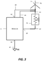
FIG. 3: Depicts a further protection arrangement according to various embodiments of this disclosure;
FIG. 4: Depicts an exemplary process flow.
DESCRIPTION OF EMBODIMENTS
The present embodiments will now be described more fully hereinafter with reference to the accompanying drawings, in which exemplary embodiments are shown. The embodiments are not to be construed as limited to the embodiments set forth herein. Rather, these embodiments are provided so that this disclosure will be thorough and complete, and will fully convey their scope to those skilled in the art. In the drawings, like numbers refer to like elements throughout.
In the following description and/or claims, the terms “on,” “overlying,” “disposed on” and “over” may be used in the following description and claims. “On,” “overlying,” “disposed on” and “over” may be used to indicate that two or more elements are in direct physical contact with one another. Also, the term “on,”, “overlying,” “disposed on,” and “over”, may mean that two or more elements are not in direct contact with one another. For example, “over” may mean that one element is above another element while not contacting one another and may have another element or elements in between the two elements. Furthermore, the term “and/or” may mean “and”, it may mean “or”, it may mean “exclusive-or”, it may mean “one”, it may mean “some, but not all”, it may mean “neither”, and/or it may mean “both”, although the scope of claimed subject matter is not limited in this respect.
A listing of various components for the instant figures is detailed in Table I.
TABLE 1
Item Description
1 A fault protection arrangement
2 Details of a fault protection arrangement
3 A fault protection arrangement utilizing a 3-wire measurement
technique
4 Exemplary process flow diagram
9 Neutral grounding resistor monitor
10 Signal source waveform generator
11 Signal source amplifier (current or voltage output)
12 Output current measurement resistor element
13 Output current measurement amplifier and signal conditioning
14 Overvoltage protection
15 Voltage measurement circuitry
16 Voltage measurement amplifier and signal conditioning
17 Low-side current sense circuity
18 Low-side current sense amplifier and signal conditioning
19 Unidirectional two-terminal high-voltage current limiting
apparatus
20 Unidirectional two-terminal high-voltage current limiting
apparatus
21 Signal processing and control device
22 Trip control relay
23 Protective earth connection detection apparatus
24 Overvoltage protection
40 Coupling wire between monitor output and transformer
neutralizing point
41 Coupling wire between transformer neutralizing point
and high-side terminal of neutral grounding resistor
42 Coupling wire between low-side terminal of neutral grounding
resistor and the neutral grounding resistor monitor
43 Coupling wire between neutral grounding resistor monitor
and protective earth
44 Coupling wire for voltage sense circuit to cancel parasitic
effects of wires 40 and 41
60 Coupling terminal between the neutral grounding resistor monitor
and the transformer neutralizing point, located on the
neutral grounding resistor monitor
61 Coupling terminal between the neutral grounding resistor high-side
connection and the transformer neutralizing point, located on
the neutral grounding resistor
62 Coupling terminal between the neutral grounding resistor low-side
connection and the neutral grounding resistor monitor low-side
terminal, located on the neutral grounding resistor
63 Coupling terminal between the neutral grounding resistor
low-side connection and th eneutral grounding resistor monitor
low-side terminal, located on the neutral grounding resistor monitor
64 Coupling terminal between the neutral grounding resistor
monitor ground terminal and the power system protective
earth connection intended for power system reference
65 Coupling terminal between the neutral grounding resistor
monitor ground terminal and the power system protective
earth connection intended for protective earth
integrity monitoring
70 Protected 3-phase power system transformer secondary
71 Transformer neutralizing point connection
72 Neutral grounding resistor
73 Electronically actuated disconnect
In various embodiments, systems and devices are included for providing fault protection. FIG. 1 shows fault protection arrangement 1 according to various embodiments of the disclosure. FIG. 2A presents detail of one variant of protection arrangement 1, according to various embodiments of this disclosure; The fault protection arrangement 1 includes transformer secondary 70, transformer neutralizing point 71, coupled to the a first non-ground end, shown as high-side connection point 61 of neutral grounding resistor 72 through wire 41.
A second non-ground end, shown as the low-side connection point 62 of the neutral grounding resistor 72, is coupled to the neutral grounding resistor monitor, shown as neutral grounding resistor monitor assembly 9 between second connection point 62 and connection point 63 via coupling wire 42. A monitor assembly shown as neutral grounding resistor monitor assembly 9 provides a low-ohmic path to protective earth connecting to a terminal (64) via coupling wire 43. The neutral grounding resistor monitor assembly 9 injects a signal to transformer neutralizing point 71 from connection terminal 60 via coupling wire 40. Voltages induced within neutral grounding resistor monitor assembly 9 and currents that are measured leaving terminal 60 and returning through terminal 63 as a result of injected signals are used to calculate the DC resistance of the neutral grounding resistor 72. An advantage afforded by the configuration of FIG. 1 and in the embodiments to follow is that, the injection signal provided by the neutral grounding resistor monitor assembly does not travel through a capacitive/inductive circuit as injected through the neutral grounding resistor, and therefore may be injected with zero phase shift, rendering leakage measurement more facile.
Neutral grounding resistor monitor assembly 9 is shown in greater detail within FIG. 2A. The detail within FIG. 2 will be described by the following hierarchy: primary signal path items 10, 11, 12, 19, 20, 60, 40, 71, 41, 61, 72, 62, 42, 63, 17, 64, 43; measurement signals and signal conditioning items 13, 14, 15, 16, 18, 24, 52, 53, 55; control items 21, 22, 23, 50, 51, 54, 56, 73. A signal source, shown as signal generator 10, may be configured to provide excitation to amplifier 11 in the form of various waveform profiles, including DC levels, AC signals and arbitrary waveforms. The operation mode of amplifier 11 may be configured for voltage amplification, current amplification, transconductance amplification or transimpedance amplification. The output of amplifier 11 is monitored through current sense resistor 12 and voltage monitor 15. Generally, the signal source generator 10 may be configured to generate a current-controlled output chosen from one of: DC, AC, and arbitrary waveform, or may be configured to generate a voltage-controlled output chosen from one of: DC, AC, and arbitrary waveform. Generally elements of at least a second current sense circuit as described herein may be arranged as a non-contact sense circuit.
Current-limiting element 19 and current limiting element 20 are provided in series with the current sense resistor 12 and voltage monitor 15, and are arranged to provide an AC current path, which maximum is limited to a value survivable by the electronic measurement path. In various additional embodiments of neutral grounding resistor monitor assembly 9, this path can be configured as a DC path by just providing current limiting element 19 or current limiting element 20. In various non-limiting embodiments, the current-limiting element 19 and current limiting element 20 are configured as a two-terminal high-voltage current-limiting electronic device coupled between the signal source and the transformer neutralizing-point.
Furthermore, in different variants, the current limiting element 19 and current limiting element 20 can have their voltage breakdown characteristic augmented by increasing the number of series elements. Voltage breakdown becomes important when during the normal course of operation, a ground-fault occurs in a manner forcing the voltage at transformer neutralizing point 71 to system line voltage. Full system voltage will then be impressed on terminal 60 via coupling wire 40. The combination of current limiting element 19, current limiting element 20 and an overvoltage protection element 14 together form a protective circuit, ensuring that the provided electronics are not electrically overstressed. The combination of current limiting element 19 and current limiting element 20 further allows for measurements of the neutral grounding resistor 72 to be made during partially energized conditions.
In operation, the integrity of the conduction path including connection items 60, 61, 62, 63 and 64 plus wire items 40, 41, 42, and 43 is to be continuously monitored. A probe or injection signal from the signal generator 10 may be sent out at least once per second, for example. In a first and a third embodiment (see FIGS. 1 and 3), the continuity monitoring path is used as the primary measurement path. As shown in FIG. 1, a current sense element 17 is provided between second connection point 62, on the low side of neutral grounding resistor 72, and a protective earth connection item 64. During ideal conditions, the current provided by amplifier 11 and measured through resistor 12 will be the same as current travelling through the primary signal path and through a current sense element 17. The primary signal path described above is to be measured by various components, beginning with current sense resistor 12 and amplifier 13, in order to create a signal I1 (52). Signal I1 (52) provides a representation of the output current to transformer neutralizing point 71. When transformer 70 has zero parasitic loss between the power conductors and protective earth, signal I1 (52) will match signal 12 (55), measured by current sensor 17 and conditioned by amplifier 18.
The current sense element 17 is designed have a low-ohmic characteristic so as to not materially affect the value of neutral grounding resistor 72. The current passing through the primary path will create a voltage in accordance with Ohm's law. This voltage may be measured by a first voltage sense circuit, shown as monitoring network or voltage monitor 15, at terminal 60. This voltage will be conditioned by an amplifier 16 into a signal V1 (53). Referring also again to FIG. 2A, amplifier 16 is protected by an overvoltage protection network 24.
Further embodiments may include a second voltage measurement circuit at the high-side connection 61 of neutral grounding resistor 72. This embodiment may include a second monitoring network similar to monitoring network (voltage monitor) 15 and a conditioning circuit of the same design as amplifier 16 and results in the creation of a second voltage monitoring signal V2. An example of this embodiment is shown in FIG. 2B, where a neutral grounding resistor monitor assembly 9A is shown, with like components to the aforementioned components of FIG. 2A having the same reference numbers. In this example, a second voltage sense circuit is shown as monitoring network 15A, this time, coupled to a terminal 60A along wire 41. The monitoring network 15A outputs the second voltage monitoring signal V2 as shown.
Each embodiment of the aforementioned embodiments may entail processing and generating a multiplicity of measurement signals 52, 53 and 55 and control signals 50, 51, 54 and 56. Processing and generation of these signals is accomplished using the signal processing and control unit 21. Signal EN (50) provides an enable signal to the output amplifier 11 such that when this signal is logic high there is generated an output that tracks signal generator 10, and when the value is logic low the output performs as a high-impedance input. Processing and control unit 21 may include a processing algorithm to utilize two signals, signal I1 (52) and signal V1 (53) in a manner to generate a feedback signal depicted as signal FB (51). Signal 51 is a feedback signal from the output current amplifier 11 to ensure the output current signal represents what the signal processing and control unit 21 thinks is being sent out.
The protective feature of the neutral grounding resistor monitor assembly 9 has a primary output function. This primary function is an aggregation of the previously described functionality and results in a signal TRIP (54), which signal is coupled to operate a relaying device (22) to affect power system disconnect component 73. Various embodiments of neutral grounding resistor monitor assembly 9 may include an apparatus to detect the integrity of protective earth connection items 64 and 65 including the coupling wire connections between the terminal and protective earth. Protective earth detection element 23 is disposed between a first protective earth connection item 64 and a second protective earth connection item 65, and is arranged to generate signal LOSS OF PE (56) for processing device 21. Protective earth detection element 23 works by having a separate isolated power supply referencing PE via physical isolation from the other PE nets. This circuit will just works if the “isolated” PE provides a current path with the real PE.
FIG. 3 presents a third embodiment of a neutral grounding resistor monitor assembly 9 which embodiment includes a second voltage monitoring circuit to generate signal V2 as described above, and detailed at FIG. 2B. The advantage of this embodiment is that losses due to parasitic line-to-earth loads can be more readily determined. Besides more accurately determining unintended loads, the value of neutral grounding resistor 72 can be more accurately determined. Further embodiments can increase the accuracy of the measurement by including a fourth wire to sense the low-side connection 62 of the neutral grounding resistor 72. This embodiment may require a voltage measurement across neutral grounding resistor 72.
FIG. 4 presents an exemplary process flow 100. At block 101, a power system is connected to a fault protection arrangement. The fault protection arrangement may include a neutral grounding resistor as well as a monitor assembly. At block 102, the resistance of the neutral grounding resistor is probed by sending an injection signal from the monitor assembly. At block 103, the resistance of the neutral grounding resistor is calculated by dividing a measured voltage by a measured current. At block 104, a trip signal is generated when the resistance of the neutral grounding resistor falls outside of a predetermined range. In various additional embodiments, a trip signal may be generated when various specific conditions are met. For example, a trip signal to disconnect the power system may be sent when just a ratio of V1/I1, just a ratio of V2/I2 or both the ratio of V1/I1 and the ratio of V2/I2 fall outside of a predetermined range. Also, there may be a trip signal sent upon the measurement of voltage and/or current depending on safety requirements.
While the present embodiments have been disclosed with reference to certain embodiments, numerous modifications, alterations and changes to the described embodiments are possible while not departing from the sphere and scope of the present disclosure, as defined in the appended claims. Accordingly, the present embodiments are not to be limited to the described embodiments, and may have the full scope defined by the language of the following claims, and equivalents thereof.

Claims (19)

What is claimed is:
1. A fault protection arrangement, comprising:
a neutral grounding resistor comprising:
a first end, connected to a neutralizing point, and a second end;
a neutral grounding resistance monitor assembly, directly coupled to the second end of the neutral grounding resistor, and comprising:
a signal source coupled to the neutralizing point;
a first current sense circuit coupled between the signal source and the neutralizing-point;
a first voltage sense circuit coupled between the signal source and the neutralizing-point;
a second current sense circuit, comprising a current sensor, coupled between the second end of the neutral grounding resistor and a protective earth connection;
a second protective earth connection, directly coupled to the signal source; and
a protective earth detection element, disposed between the protective earth connection and the second protective earth connection.
2. The fault protection arrangement of claim 1, further comprising:
a two-terminal high-voltage current-limiting electronic device coupled between the signal source and the neutralizing-point.
3. The fault protection arrangement of claim 1, the signal source configured to generate a current-controlled output chosen from one of: DC, AC, and arbitrary waveform.
4. The fault protection arrangement of claim 1, the signal source configured to generate a voltage-controlled output chosen from one of: DC, AC, and arbitrary waveform.
5. The fault protection arrangement of claim 1, wherein the second current sense circuit comprises a non-contact sense circuit, the fault protection arrangement further comprising: a signal processing and control unit, coupled to the first current sense circuit, second current sense circuit, and first voltage sense circuit.
6. The fault protection arrangement of claim 5, further comprising a power system disconnect component, coupled to the signal processing and control unit.
7. The fault protection arrangement of claim 1, wherein the neutralizing point is a neutralizing point of a three phase transformer.
8. A fault protection arrangement, comprising:
a neutral grounding resistor comprising:
a first end, connected to a neutralizing point, and a second end;
a neutral grounding resistance monitor assembly, directly coupled to the second end of the neutral grounding resistor, and comprising:
a signal source coupled to the neutralizing-point;
a first current sense circuit coupled between the signal source and the neutralizing-point;
a first voltage sense circuit coupled between the signal source and the neutralizing-point;
a second current sense circuit, comprising a current sensor coupled between the second end of the neutral grounding resistor and a protective earth connection; and
a second voltage sense circuit, coupled to the first end of the neutral grounding resistor.
9. The fault protection arrangement of claim 8, wherein the second voltage sense circuit is coupled to measure a voltage without error induced from a wire coupling the first end of the neutral grounding resistor to the neutralizing point and a wire coupling an output form the signal source to the neutralizing point.
10. The fault protection arrangement of claim 8, further comprising:
a two-terminal high-voltage current-limiting electronic device coupled between the signal source and the neutralizing point.
11. The fault protection arrangement of claim 8, the signal source configured to generate a current-controlled output chosen from one of: DC, AC, and arbitrary waveform.
12. The fault protection arrangement of claim 8, the signal source configured to generate a voltage-controlled output chosen from one of: DC, AC, arbitrary waveform.
13. The fault protection arrangement of claim 8, further comprising:
a second protective earth connection, directly coupled to the signal source; and
a protective earth detection element, disposed between the protective earth connection and the second protective earth connection.
14. The fault protection arrangement of claim 8, wherein the neutralizing point is a neutral of a three phase transformer.
15. The fault protection arrangement of claim 8, the fault protection arrangement further comprising: a signal processing and control unit, coupled to the first current sense circuit, second current sense circuit, and first voltage sense circuit.
16. The fault protection arrangement of claim 15, further comprising a power system disconnect component, coupled to the signal processing and control unit.
17. A fault protection method, comprising:
connecting a power system to a fault protection arrangement, the fault protection arrangement comprising:
a neutral grounding resistor comprising:
a first end, connected to a neutralizing point, and a second end; and
a neutral grounding resistance monitor assembly, coupled to the first end and comprising a plurality of sense circuits;
sending a signal from a signal source of the neutral grounding resistance monitor assembly to a neutralizing point of the power system;
sensing a first current (I1) between the signal source and the neutralizing point;
sensing a first voltage (V1) between the signal source and the neutralizing point;
sensing a second current (I2) between the second end and a protective earth terminal; and
determining a ratio of V1/I1 and a ratio of V2/I2; and
sending a trip signal to disconnect the power system, when just the ratio of V1/I1, just the ratio of V2/I2 or both the ratio of V1/I1 and the ratio of V2/I2 fall outside of a predetermined range.
18. The method of claim 17, further comprising:
sensing a second voltage, between the neutralizing point and first end of the neutral grounding resistor.
19. The method of claim 18, further comprising:
sending the signal through a two-terminal high-voltage current-limiting circuit, coupled between the signal source and the neutralizing point, wherein the signal source is current-controlled or voltage-controlled.
US16/876,705 2020-05-18 2020-05-18 Ground fault protection circuit and techniques Active US11368014B2 (en)

Priority Applications (4)

Application Number Priority Date Filing Date Title
US16/876,705 US11368014B2 (en) 2020-05-18 2020-05-18 Ground fault protection circuit and techniques
AU2021202709A AU2021202709A1 (en) 2020-05-18 2021-04-30 Ground fault protection circuit and techniques
CA3116953A CA3116953A1 (en) 2020-05-18 2021-05-03 Ground fault protection circuit and techniques
MX2021005736A MX2021005736A (en) 2020-05-18 2021-05-14 Ground fault protection circuit and techniques.

Applications Claiming Priority (1)

Application Number Priority Date Filing Date Title
US16/876,705 US11368014B2 (en) 2020-05-18 2020-05-18 Ground fault protection circuit and techniques

Publications (2)

Publication Number Publication Date
US20210359507A1 US20210359507A1 (en) 2021-11-18
US11368014B2 true US11368014B2 (en) 2022-06-21

Family

ID=78511960

Family Applications (1)

Application Number Title Priority Date Filing Date
US16/876,705 Active US11368014B2 (en) 2020-05-18 2020-05-18 Ground fault protection circuit and techniques

Country Status (4)

Country Link
US (1) US11368014B2 (en)
AU (1) AU2021202709A1 (en)
CA (1) CA3116953A1 (en)
MX (1) MX2021005736A (en)

Citations (20)

* Cited by examiner, † Cited by third party
Publication number Priority date Publication date Assignee Title
US4589048A (en) * 1983-03-23 1986-05-13 Mitsubishi Denki Kabushiki Kaisha Apparatus for detecting ground fault in variable-voltage variable-frequency power system
US20030197989A1 (en) * 2002-04-05 2003-10-23 Smc Electrical Products, Inc. Method and apparatus for high impedance grounding of medium voltage AC drives
US20090160454A1 (en) * 2006-08-18 2009-06-25 Johansson Stefan G Ground Fault Detection
US20090254297A1 (en) * 2006-12-22 2009-10-08 Tord Bengtsson Arrangement and Method for Determining an Electrical Feature
US20100217546A1 (en) * 2009-02-20 2010-08-26 Anthony Locker Methods and Apparatuses for Detecting Faults in Electrical Power Systems
US8405940B2 (en) * 2009-10-13 2013-03-26 Schweitzer Engineering Laboratories Inc Systems and methods for generator ground fault protection
US20140177117A1 (en) * 2012-12-20 2014-06-26 Intermountain Electronics, Inc Ground monitor current sensing
US20150048840A1 (en) * 2012-04-12 2015-02-19 Littelfuse, Inc. Neutral grounding resistor monitor
US20150061690A1 (en) * 2013-08-29 2015-03-05 Intermountain Electronics, Inc. Watchdog circuit for ground monitor current sensing
US20150212139A1 (en) * 2014-01-24 2015-07-30 GF Technologies, LLC Sensitive and selective ground fault detection
US20150326004A1 (en) * 2014-05-09 2015-11-12 Intermountain Electronics, Inc. Arc-free capacitor trip device
US20150346264A1 (en) * 2013-08-29 2015-12-03 Intermountain Electronics, Inc. Multi-frequency ground monitor current sensing without a dc component
US20150346262A1 (en) * 2013-08-29 2015-12-03 Intermountain Electronics, Inc. Multi-frequency ground monitor current sensing
US9431820B2 (en) * 2012-03-30 2016-08-30 Thermo King Corporation Vehicle or environment-controlled unit having a multiphase alternator with a protected high-voltage bus
US9500710B2 (en) * 2012-10-15 2016-11-22 Siemens Energy, Inc. Generator neutral ground monitoring system and method
US20180315573A1 (en) * 2017-04-28 2018-11-01 Intermountain Electronics, Inc. Phase operation indicator
US10511164B2 (en) * 2015-03-20 2019-12-17 Ams Co., Ltd Apparatus for preventing electric shock in event of flooding and method therefor
US10530144B2 (en) * 2014-12-18 2020-01-07 Mohd Hasan Ali Apparatus for mitigation of adverse effects of geomagnetically induced currents on transformers
US20210063495A1 (en) * 2019-08-27 2021-03-04 Intermountain Electronics, Inc. Ground monitor with smart frequency selection
US11108222B2 (en) * 2018-03-16 2021-08-31 Littelfuse, Inc. Monitor device, ground fault protection circuit and techniques

Patent Citations (20)

* Cited by examiner, † Cited by third party
Publication number Priority date Publication date Assignee Title
US4589048A (en) * 1983-03-23 1986-05-13 Mitsubishi Denki Kabushiki Kaisha Apparatus for detecting ground fault in variable-voltage variable-frequency power system
US20030197989A1 (en) * 2002-04-05 2003-10-23 Smc Electrical Products, Inc. Method and apparatus for high impedance grounding of medium voltage AC drives
US20090160454A1 (en) * 2006-08-18 2009-06-25 Johansson Stefan G Ground Fault Detection
US20090254297A1 (en) * 2006-12-22 2009-10-08 Tord Bengtsson Arrangement and Method for Determining an Electrical Feature
US20100217546A1 (en) * 2009-02-20 2010-08-26 Anthony Locker Methods and Apparatuses for Detecting Faults in Electrical Power Systems
US8405940B2 (en) * 2009-10-13 2013-03-26 Schweitzer Engineering Laboratories Inc Systems and methods for generator ground fault protection
US9431820B2 (en) * 2012-03-30 2016-08-30 Thermo King Corporation Vehicle or environment-controlled unit having a multiphase alternator with a protected high-voltage bus
US20150048840A1 (en) * 2012-04-12 2015-02-19 Littelfuse, Inc. Neutral grounding resistor monitor
US9500710B2 (en) * 2012-10-15 2016-11-22 Siemens Energy, Inc. Generator neutral ground monitoring system and method
US20140177117A1 (en) * 2012-12-20 2014-06-26 Intermountain Electronics, Inc Ground monitor current sensing
US20150346264A1 (en) * 2013-08-29 2015-12-03 Intermountain Electronics, Inc. Multi-frequency ground monitor current sensing without a dc component
US20150346262A1 (en) * 2013-08-29 2015-12-03 Intermountain Electronics, Inc. Multi-frequency ground monitor current sensing
US20150061690A1 (en) * 2013-08-29 2015-03-05 Intermountain Electronics, Inc. Watchdog circuit for ground monitor current sensing
US20150212139A1 (en) * 2014-01-24 2015-07-30 GF Technologies, LLC Sensitive and selective ground fault detection
US20150326004A1 (en) * 2014-05-09 2015-11-12 Intermountain Electronics, Inc. Arc-free capacitor trip device
US10530144B2 (en) * 2014-12-18 2020-01-07 Mohd Hasan Ali Apparatus for mitigation of adverse effects of geomagnetically induced currents on transformers
US10511164B2 (en) * 2015-03-20 2019-12-17 Ams Co., Ltd Apparatus for preventing electric shock in event of flooding and method therefor
US20180315573A1 (en) * 2017-04-28 2018-11-01 Intermountain Electronics, Inc. Phase operation indicator
US11108222B2 (en) * 2018-03-16 2021-08-31 Littelfuse, Inc. Monitor device, ground fault protection circuit and techniques
US20210063495A1 (en) * 2019-08-27 2021-03-04 Intermountain Electronics, Inc. Ground monitor with smart frequency selection

Also Published As

Publication number Publication date
US20210359507A1 (en) 2021-11-18
CA3116953A1 (en) 2021-11-18
AU2021202709A1 (en) 2021-12-02
MX2021005736A (en) 2021-11-19

Similar Documents

Publication Publication Date Title
US10126345B2 (en) Device and method for insulation monitoring in a power supply system including a high-resistance grounded neutral point
EP1724597B1 (en) System and method for determining location of phase-to-earth fault
CN104459459B (en) Insulation fault location system and insulated monitoring system
US8098072B2 (en) Partial discharge coupler for application on high voltage generator bus works
US7969696B2 (en) Ground fault detection and localization in an ungrounded or floating DC electrical system
KR101009595B1 (en) Apparatus for measuring ground leakage current in non-grounded dc power line and detecting method therefor
US10359461B2 (en) Integrated circuit protection during high-current ESD testing
JP5903261B2 (en) Testing transient voltage protection devices
KR960006867B1 (en) Method and electrical measuring apparatus for analyzing the impedance of the source of an actual alternating voltage
US11946954B2 (en) Absence of voltage detection device
US11353486B2 (en) Circuit arrangement having an active measuring voltage for determining an insulation resistance against ground potential in an ungrounded power supply system
Loos et al. Fault direction method in compensated network using the zero sequence active energy signal
CN108983041B (en) Device for detecting faults in electrical lines
US11539200B2 (en) Monitor device, ground fault protection circuit and techniques
CN113924706A (en) Localization of ground faults in a direct current network
US11368014B2 (en) Ground fault protection circuit and techniques
CN107210585B (en) Multi-stage, coordinated surge arrester circuit
Sheikh et al. Detection of high impedance fault in DC microgrid
KR101070815B1 (en) method for discriminating fault line and phase in ungrounded distribution system
CN104049169A (en) Grounding detection apparatus and method
JP2018096804A (en) Insulation resistance measurement method of dc power supply circuit
RU2623363C1 (en) Method and device for monitoring cable core soundness in track circuits
Guldbrand System earthing
CN111398849B (en) Measuring system for detecting equipment and line faults
US6943567B2 (en) Method for detecting the operability of a number of identical zener diodes that are connected in parallel to one another and to a solenoid

Legal Events

Date Code Title Description
FEPP Fee payment procedure

Free format text: ENTITY STATUS SET TO UNDISCOUNTED (ORIGINAL EVENT CODE: BIG.); ENTITY STATUS OF PATENT OWNER: LARGE ENTITY

AS Assignment

Owner name: LITTELFUSE, INC., ILLINOIS

Free format text: ASSIGNMENT OF ASSIGNORS INTEREST;ASSIGNOR:JENSEN, KRISTOPHOR RAY;REEL/FRAME:053671/0152

Effective date: 20200831

STPP Information on status: patent application and granting procedure in general

Free format text: NON FINAL ACTION MAILED

STPP Information on status: patent application and granting procedure in general

Free format text: NOTICE OF ALLOWANCE MAILED -- APPLICATION RECEIVED IN OFFICE OF PUBLICATIONS

STPP Information on status: patent application and granting procedure in general

Free format text: PUBLICATIONS -- ISSUE FEE PAYMENT VERIFIED

STCF Information on status: patent grant

Free format text: PATENTED CASE