US11359834B2 - Air conditioner - Google Patents
Air conditioner Download PDFInfo
- Publication number
- US11359834B2 US11359834B2 US16/896,046 US202016896046A US11359834B2 US 11359834 B2 US11359834 B2 US 11359834B2 US 202016896046 A US202016896046 A US 202016896046A US 11359834 B2 US11359834 B2 US 11359834B2
- Authority
- US
- United States
- Prior art keywords
- flap
- sub
- air
- rotation axis
- main flap
- Prior art date
- Legal status (The legal status is an assumption and is not a legal conclusion. Google has not performed a legal analysis and makes no representation as to the accuracy of the status listed.)
- Active
Links
Images


Classifications
-
- F—MECHANICAL ENGINEERING; LIGHTING; HEATING; WEAPONS; BLASTING
- F24—HEATING; RANGES; VENTILATING
- F24F—AIR-CONDITIONING; AIR-HUMIDIFICATION; VENTILATION; USE OF AIR CURRENTS FOR SCREENING
- F24F13/00—Details common to, or for air-conditioning, air-humidification, ventilation or use of air currents for screening
- F24F13/08—Air-flow control members, e.g. louvres, grilles, flaps or guide plates
- F24F13/10—Air-flow control members, e.g. louvres, grilles, flaps or guide plates movable, e.g. dampers
- F24F13/14—Air-flow control members, e.g. louvres, grilles, flaps or guide plates movable, e.g. dampers built up of tilting members, e.g. louvre
- F24F13/1413—Air-flow control members, e.g. louvres, grilles, flaps or guide plates movable, e.g. dampers built up of tilting members, e.g. louvre using more than one tilting member, e.g. with several pivoting blades
-
- F—MECHANICAL ENGINEERING; LIGHTING; HEATING; WEAPONS; BLASTING
- F24—HEATING; RANGES; VENTILATING
- F24F—AIR-CONDITIONING; AIR-HUMIDIFICATION; VENTILATION; USE OF AIR CURRENTS FOR SCREENING
- F24F1/00—Room units for air-conditioning, e.g. separate or self-contained units or units receiving primary air from a central station
- F24F1/0007—Indoor units, e.g. fan coil units
- F24F1/0011—Indoor units, e.g. fan coil units characterised by air outlets
- F24F1/0014—Indoor units, e.g. fan coil units characterised by air outlets having two or more outlet openings
-
- F—MECHANICAL ENGINEERING; LIGHTING; HEATING; WEAPONS; BLASTING
- F24—HEATING; RANGES; VENTILATING
- F24F—AIR-CONDITIONING; AIR-HUMIDIFICATION; VENTILATION; USE OF AIR CURRENTS FOR SCREENING
- F24F1/00—Room units for air-conditioning, e.g. separate or self-contained units or units receiving primary air from a central station
- F24F1/0007—Indoor units, e.g. fan coil units
- F24F1/0043—Indoor units, e.g. fan coil units characterised by mounting arrangements
- F24F1/0047—Indoor units, e.g. fan coil units characterised by mounting arrangements mounted in the ceiling or at the ceiling
-
- F—MECHANICAL ENGINEERING; LIGHTING; HEATING; WEAPONS; BLASTING
- F24—HEATING; RANGES; VENTILATING
- F24F—AIR-CONDITIONING; AIR-HUMIDIFICATION; VENTILATION; USE OF AIR CURRENTS FOR SCREENING
- F24F13/00—Details common to, or for air-conditioning, air-humidification, ventilation or use of air currents for screening
- F24F13/02—Ducting arrangements
- F24F13/0227—Ducting arrangements using parts of the building, e.g. air ducts inside the floor, walls or ceiling of a building
-
- F—MECHANICAL ENGINEERING; LIGHTING; HEATING; WEAPONS; BLASTING
- F24—HEATING; RANGES; VENTILATING
- F24F—AIR-CONDITIONING; AIR-HUMIDIFICATION; VENTILATION; USE OF AIR CURRENTS FOR SCREENING
- F24F13/00—Details common to, or for air-conditioning, air-humidification, ventilation or use of air currents for screening
- F24F13/08—Air-flow control members, e.g. louvres, grilles, flaps or guide plates
- F24F13/10—Air-flow control members, e.g. louvres, grilles, flaps or guide plates movable, e.g. dampers
- F24F13/14—Air-flow control members, e.g. louvres, grilles, flaps or guide plates movable, e.g. dampers built up of tilting members, e.g. louvre
- F24F13/142—Air-flow control members, e.g. louvres, grilles, flaps or guide plates movable, e.g. dampers built up of tilting members, e.g. louvre using pivoting blades with intersecting axles
-
- F—MECHANICAL ENGINEERING; LIGHTING; HEATING; WEAPONS; BLASTING
- F24—HEATING; RANGES; VENTILATING
- F24F—AIR-CONDITIONING; AIR-HUMIDIFICATION; VENTILATION; USE OF AIR CURRENTS FOR SCREENING
- F24F13/00—Details common to, or for air-conditioning, air-humidification, ventilation or use of air currents for screening
- F24F13/20—Casings or covers
-
- F—MECHANICAL ENGINEERING; LIGHTING; HEATING; WEAPONS; BLASTING
- F24—HEATING; RANGES; VENTILATING
- F24F—AIR-CONDITIONING; AIR-HUMIDIFICATION; VENTILATION; USE OF AIR CURRENTS FOR SCREENING
- F24F13/00—Details common to, or for air-conditioning, air-humidification, ventilation or use of air currents for screening
- F24F13/08—Air-flow control members, e.g. louvres, grilles, flaps or guide plates
- F24F13/10—Air-flow control members, e.g. louvres, grilles, flaps or guide plates movable, e.g. dampers
- F24F13/14—Air-flow control members, e.g. louvres, grilles, flaps or guide plates movable, e.g. dampers built up of tilting members, e.g. louvre
- F24F13/1426—Air-flow control members, e.g. louvres, grilles, flaps or guide plates movable, e.g. dampers built up of tilting members, e.g. louvre characterised by actuating means
- F24F2013/1433—Air-flow control members, e.g. louvres, grilles, flaps or guide plates movable, e.g. dampers built up of tilting members, e.g. louvre characterised by actuating means with electric motors
-
- F—MECHANICAL ENGINEERING; LIGHTING; HEATING; WEAPONS; BLASTING
- F24—HEATING; RANGES; VENTILATING
- F24F—AIR-CONDITIONING; AIR-HUMIDIFICATION; VENTILATION; USE OF AIR CURRENTS FOR SCREENING
- F24F13/00—Details common to, or for air-conditioning, air-humidification, ventilation or use of air currents for screening
- F24F13/08—Air-flow control members, e.g. louvres, grilles, flaps or guide plates
- F24F13/10—Air-flow control members, e.g. louvres, grilles, flaps or guide plates movable, e.g. dampers
- F24F13/14—Air-flow control members, e.g. louvres, grilles, flaps or guide plates movable, e.g. dampers built up of tilting members, e.g. louvre
- F24F13/1426—Air-flow control members, e.g. louvres, grilles, flaps or guide plates movable, e.g. dampers built up of tilting members, e.g. louvre characterised by actuating means
- F24F2013/1446—Air-flow control members, e.g. louvres, grilles, flaps or guide plates movable, e.g. dampers built up of tilting members, e.g. louvre characterised by actuating means with gearings
Definitions
- the present invention relates to an air conditioner, and more particularly, to an air conditioner including a ceiling-embedded type indoor unit configured to discharge air into an indoor room through an air outlet simultaneously sucking indoor air through an air inlet.
- a ceiling-embedded type indoor unit includes a main flap and a sub-flap configured to control a direction and volume of air discharged into an indoor room.
- each of the flaps is rotatably installed at an air outlet, controlled to blow air to feet during a heating operation, and controlled to blow air in a lateral direction during a cooling operation such that the entire room is air-conditioned.
- An aspect of the present disclosure is to provide an air conditioner capable of guiding air in a desired direction with an adjusted speed without marring the appearance to solve the above-described problems.
- an air conditioner including a ceiling-embedded type indoor unit configured to discharge air into an indoor room through an air outlet simultaneously sucking indoor air through an air inlet
- the air conditioner include: a main flap configured to guide a direction of air discharged from the air outlet in a preset direction; and a sub-flap configured to guide the direction of air between the main flap and the sub-flap in the preset direction, wherein a length of the main flap in a direction where air flows is longer than that of the sub-flap in the direction where air flows.
- the main flap include: a first guide part configured to guide air discharged from the air outlet downward; and a second guide part rotatably connected to the first guide part and configured to guide the air guided downward by the first guide part in a different direction.
- the main flap extends downward from the air outlet.
- a width of the second guide part is greater than that of the sub-flap.
- the second guide part is disposed at an end of the first guide part.
- a vertical length of the main flap is greater than that of the sub-flap.
- the second guide part has a flow path forming surface formed on one surface thereof, the sub-flap has a flow path forming surface formed on a lower surface thereof, and an air flow path is formed between the flow path forming surface of the second guide part and the flow path forming surface of the sub-flap.
- the rotation shaft of the second guide part is disposed at an upper end of the flow path forming surface of the second guide part, and the rotation shaft of the sub-flap is disposed at an upper end of the flow path forming surface of the sub-flap.
- the air outlet has a rectangular shape
- the main flap has a plate shape installed at the air outlet
- the sub-flap has a plate shape installed at the air outlet.
- the second guide part has an elliptical shape.
- the main flap is configured to surround the sub-flap when the second guide part rotates about the rotation shaft.
- the main flap further include an elevating device to move up and down with respect to the air outlet.
- the main flap include a first rotating device configured to rotate the second guide part.
- the air conditioner including a second rotating device configured to rotate the sub-flap.
- the main flap closes the air outlet simultaneously covering the sub-flap to be invisible in an operation stop state.
- the air conditioner including a front panel provided with the air inlet and the air outlet, wherein an indoor side surface of the main flap is formed on the same plane as an indoor side surface of the front panel in an operation stop state.
- the air conditioner according further including: a main flap driving device configured to rotate the main flap about a rotation shaft; and a sub-flap driving device disposed between the main flap driving device and the sub-flap and configured to rotate the sub-flap about another rotation shaft in linkage to rotational movement of the main flap.
- the sub-flap driving device include a linking device disposed between the main flap and the sub-flap.
- the main flap driving device raises and lowers the main flap between a closed position in which the air outlet is closed and an open position disposed at a lower position than the closed position in which the air outlet is open and rotates the main flap located at the open position about the rotation shaft.
- effects of guiding air in a desired direction with an adjusted speed may be obtained without marring designability.
- effects of inhibiting so-called cold draft (downward flow of cold air) that is an unpleasant feeling caused during a cooling operation may be obtained by guiding most of conditioned air to flow in a lateral direction during the cooling operation by compressing an air outlet with a main flap and a sub-flap.
- effects of preventing dew condensation occurring on each flap may be obtained without marring the appearance by disposing a heat insulating member on upper surfaces of the main flap and the sub-flap in a state where the second guide part and the sub-flap rotate and the air is discharged in a lateral direction from the air outlet.
- FIG. 1 is a view showing a ceiling-mounted indoor unit according to a first embodiment of the disclosure.
- FIG. 2 is a view showing main flaps and sub flaps according to a first embodiment of the disclosure.
- FIG. 3 is schematic configuration diagram of main flaps and sub flaps according to a first embodiment of the disclosure.
- FIG. 4 is a view showing the operation of the main flap in the first embodiment.
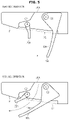
- FIG. 5 is a view showing main flaps and sub flaps in the second embodiment.
- FIG. 6 is a view showing main flaps and sub flaps in the third embodiment.
- FIG. 7 is a view showing the main flap drive mechanism and the sub-flap drive mechanism in the fourth embodiment.
- FIG. 8 is a view showing the main flap drive mechanism and the sub-flap drive mechanism in the fourth embodiment.
- FIG. 9 is a view showing the main flap drive mechanism and the sub-flap drive mechanism in the fourth embodiment.
- FIG. 10 is a view showing the main flap drive mechanism and the sub-flap drive mechanism in the fifth embodiment.
- a ceiling-embedded type indoor unit 100 according to a first exemplary embodiment that is embedded in a recessed portion of a ceiling as shown in FIG. 1 sucks indoor air through an air inlet X 1 , exchanges heat with the sucked air, and discharges the heat-exchanged air into an indoor space via an air outlet X 2 simultaneously.
- the ceiling-embedded type indoor unit 100 includes a front panel P, a fan, a bell mouth, a heat-exchanger, a drain fan, and the like.
- the front panel P is, for example, almost rectangular in a planar view.
- the front panel P having an air inlet X 1 formed at the center and a plurality of air outlets X 2 formed along each side of the front panel P is exemplarily illustrated according to the present embodiment, the concepts of the present disclosure are not limited thereto.
- the shapes of the air inlet X 1 and the air outlets X 2 are not particularly limited, the air inlet X 1 has a nearly circular shape and each air outlet X 2 has a nearly rectangular shape.
- the air outlet X 2 is formed to penetrate the front panel P as shown in FIG. 2 simultaneously constituting a lower end opening of a through-hole L through which air heat-exchanged by a heat-exchanger (not shown) flows.
- the ceiling-embedded type indoor unit 100 includes a main flap 10 and a sub-flap 20 supported via, for example, gears and links, on inner surfaces (hereinafter, referred to as support surface 30 ) of the front panel P provided along short sides of each of the air outlets X 2 and controls a direction and a speed of the air discharged through each of the air outlets X 2 by using these flaps 10 and 20 .
- the main flap 10 is provided to guide the air discharged from the air outlet X 2 in a preset direction.
- the flaps 10 and 20 extend downward to send the air to feet during a heating operation and extend laterally to perform air conditioning of the entire room during a cooling operation.
- preset direction refers to, for example, a direction selected by a user, particularly, a direction selected from a downward direction perpendicular to the air outlet X 2 and a lateral outward direction from the air outlet X 2 , i.e., an opposite direction to the air inlet X 1 .
- the main flap 10 is configured to be supported by the support surface 30 so as to move up and down and to change the direction of air discharged from the air outlet X 2 toward a space below the air outlet X 2 as illustrated in FIG. 3 .
- the main flap 10 includes a first guide part 11 extending down from the air outlet X 2 and a second guide part 12 extending from a lower end portion 111 of the first guide part 11 .
- the first guide part 11 guides air discharged from the air outlet X 2 downward and may have, for example, a plate-shaped member supported by the support surface 30 so as to move up and down in this case.
- the first guide part 11 is formed to have a flat panel shape, be installed along one long side of the air outlet X 2 (long side close to the air inlet X 1 according to the present embodiment), and extends perpendicularly down from the air outlet X 2 .
- the second guide part 12 changes the direction of air guided downward by the first guide part 11 and may be a plate-shaped member supported by the support surface 30 to extend from the lower end portion 111 of the first guide part 11 in this case.
- the second guide part 12 is separately formed from the first guide part 11 configured to be raised and lowered in linkage to the first guide part 11 .
- the second guide part 12 may be may extend in a curved form from the lower end portion 111 of the first guide part 11 in an airflow direction (preset direction).
- the second guide part 12 guides the air guided downward by the first guide part 11 in the preset direction while rotating about the lower end portion 111 of the first guide part 11 as illustrated in FIG. 3 .
- the second guide part 12 is configured to change an angle ( ⁇ ) with the first guide part 11 as the second guide part 12 is supported so as to rotate about the lower end portion 111 of the first guide part 11 or a rotation shaft C 1 installed in the vicinity thereof.
- the main flap 10 may further include a first rotating device 91 configured to rotate the second guide part 12 about the rotation shaft (C 1 ).
- the rotation shaft C 1 is set at one end 121 of the second guide part 12 closer to the first guide part 11 .
- the other end 122 may be oriented in the preset direction.
- the rotation shaft C 1 is installed at an upstream end of the second guide part 12 , more particularly, is disposed at a closest position to the upstream end of a flow path forming surface 103 of the second guide part 12 that forms a flow path through which air flows.
- the rotation shaft C 1 is installed such that a movement distance of the upstream end of the flow path forming surface 103 is the shortest when the second guide part 12 rotates.
- the second guide part 12 of the main flap 10 may guide air guided downward by the first guide part 11 in the preset direction at a position after moving downward away from the air outlet X 2 .
- the sub-flap 20 that compresses an airflow in accordance with a direction controlled by the above-described main flap 10 is a plate-shaped member installed along the other long side (long side opposite to the air inlet X 1 according to the present embodiment) of the air outlet X 2 in this case. More particularly, the sub-flap 20 is installed to face the main flap 10 at the other side of the air outlet X 2 simultaneously being rotatably supported by the support surface 30 and constitutes a flow path through which air flows together with the main flap 10 as illustrated in FIG. 3 .
- the sub-flap 20 is configured to rotate about a rotation shaft C 2 installed at one end 201 supported by the support surface 30 and to change a distance between the other end 202 and the second guide part 12 . That is, the rotation shaft C 2 is installed at an upstream end of the sub-flap 20 , more particularly, such that a distance from an upstream end of a flow path forming surface 204 of the sub-flap 20 constituting a flow path through which air flows is the shortest. In other words, the rotation shaft C 2 is installed such that a movement distance of the upstream end of the flow path forming surface 204 is the shortest when the sub-flap 20 rotates.
- the sub-flap 20 may further include a second rotating device 92 configured to rotate the sub-flap 20 about the rotation shaft C 2 .
- a length of the main flap 10 in the airflow direction is configured to be greater than that of the sub-flap 20 in the airflow direction.
- a length of the second guide part 12 of the main flap 10 in the airflow direction is configured to be greater than that of the sub-flap 20 in the airflow direction. That is, an area of the second guide part 12 of the main flap 10 in the airflow direction may be greater than that of the sub-flap 20 in the airflow direction.
- a heat insulating member (not shown) is installed on each of the above-described main flap 10 and the sub-flap 20 according to the present embodiment.
- the heat insulating member is disposed on a surface of the main flap 10 in contact with air discharged from the air outlet X 2 (the above-described flow path forming surface 103 ) and a back surface 203 of the sub-flap 20 opposite to the surface (the above-described flow path forming surface 204 ) of the sub-flap 20 in contact with the air discharged from the air outlet X 2 .
- the heat insulating member is disposed on upper surfaces of the main flap 10 and the sub-flap 20 , i.e., surfaces of the main flap 10 and the sub-flap 20 invisible from the outside there below, while air discharged from the air outlet X 2 flows in a lateral direction.
- the ceiling-embedded type indoor unit 100 further includes the elevating device configured to raise and lower the main flap 10 , the first rotating device 91 configured to rotate the second guide part 12 , and the second rotating device 92 configured to rotate the sub-flap 20 .
- the elevating device that raises and lowers the main flap 10 between an accommodation position M where wind direction controllers 11 and 12 are accommodated at upper positions than the air outlet X 2 and a control position N where the wind direction controllers 11 and 12 control the direction of air discharged from the air outlet X 2 at lower positions than the air outlet X 2 as illustrated in FIG. 4 is configured to raise and lower the wind direction controllers 11 and 12 in linkage to each other, by using, for example, a rack and pinion in this case.
- the first rotating device 91 that changes the angle ( ⁇ ) between the wind direction controllers 11 and 12 by rotating the second guide part 12 may include, for example, a motor (not shown) connected to the rotation shaft C 1 of the second guide part 12 .
- the first rotating device 91 is configured to receive a set wind direction signal indicating a direction of air discharged from the air outlet X 2 , i.e., a direction set by the user as described above, from a controller (not shown) and rotate the second guide part 12 by a predetermined angle in accordance with the set wind direction signal.
- the angle ( ⁇ ) between the wind direction controllers 11 and 12 changes, for example, within a range of 90° to 180° so that the direction of air may be controlled in a preset direction.
- the first rotating device 91 rotates the second guide part 12 by a predetermined angle.
- the second rotating device 92 that changes a distance between the other end 202 of the sub-flap 20 and the main flap 10 by rotating the sub-flap 20 may include, for example, a motor (not shown) connected to the rotation shaft C 2 of the sub-flap 20 , and the like.
- a wind speed may be controlled in the preset direction as the second rotating device 92 changes a distance between the sub-flap 20 and the first guide part 11 or a distance between the sub-flap 20 and the second guide part 12 .
- this configuration enables air conditioning of a wider area.
- hot air may be supplied to the feet during a heating operation, a temperature difference between the top and bottom in a room caused by insufficient heating around the floor and density difference.
- the second rotating device rotates the sub-flap 20 in a predetermined direction so as to be accommodated at an upper position than the air outlet X 2 together with the main flap 10 .
- the sub-flap 20 may be hidden by the main flap 10 such that the sub-flap 20 cannot be seen from the user in the case where the air is discharged in a lateral direction or the flaps 10 and 20 are accommodated at upper positions than the air outlet X 2 , and thus, designability may not deteriorate.
- the second guide part 12 is configured to change the distance between the sub-flap 20 and the second guide part 12 by rotating about the lower end portion 111 of the first guide part 11 , air discharged from the air outlet X 2 may be guided in the preset direction and compressed in the direction.
- a pressure loss of air may be considerably reduced without undesirably compressing the airflow according to conventional methods, particularly, the speed of air discharged in the lateral direction may be increased. Furthermore, air-conditioning of the entire room may be possible.
- the air outlet X 2 may be compressed by the flaps 10 and 20 and all air discharged through the air outlet X 2 may be controlled.
- the rotation shaft C 1 is installed at the upstream end of the second guide part 12 and the rotation shaft C 2 is installed at the upstream end of the sub-flap 20 , a cross-section of a flow path may be widened in comparison with conventional flow paths.
- the pressure loss may decrease, the comfort during the cooling and heating operations may be improved, and the designability may be maintained.
- Dew condensation may be caused at a dew point by a temperature decrease in each of the flaps 10 and 20 due to heat conduction on non-design surfaces through which cool air passes.
- the heat insulating member is disposed on the surfaces of the main flap 10 and the sub-flap 20 invisible from the outside there below, dew condensation may be prevented on the main flap 10 and the sub-flap 20 without marring the appearance.
- the present disclosure is not limited to the above-described embodiment.
- the first guide part and the second guide part are separate elements according to the above embodiment, the second guide part may also be connected to a lower end portion of the first guide part and rotate about the lower end portion as a central axis.
- the first rotating device is configured to rotate the second guide part by a predetermined angle while the elevating device lowers the main flap from the accommodation position to the control position according to the present embodiment
- the first rotating device may also rotate the second guide part by a predetermined angle after the elevating device lowers the main flap from the accommodation position to the control position.
- heat insulating member is disposed on the main flap and the sub-flap according to the present embodiment, dew condensation may be prevented on the flaps by applying a hollow structure to both flaps or one of the flaps.
- the plurality of air outlets is formed along each side of the front panel having a nearly rectangular shape in a planar view according to the present embodiment, the number of the air outlets is not limited thereto and one or two air outlets may also be formed in the front panel.
- main flap and the sub-flap there is no need to install the main flap and the sub-flap at all air outlets and the main flap and the sub-flap may be installed at some of the air outlets provided in the front panel such that air discharged through the air outlets is controlled.
- main flap 10 A may also be configured to control the wind direction by a single guide part 13 A as illustrated in FIG. 5 .
- the guide part 13 A is configured to rotate about a rotation shaft C 3 located at an upper position than the air outlet X 2 without being raised or lowered in a different manner from the previous embodiment
- a sub-flap 20 A that rotates about the rotation shaft C 2 in the same manner as the previous embodiment is configured to change the distance from the guide part 13 A.
- the airflow may be compressed by the main flap 10 A and the sub-flap 20 A according to the above-described configuration, air may be guided in the preset direction with no decrease in speed of the air.
- the main flap 10 A described above may overlap the sub-flap 20 A such that the sub-flap 20 A is not visible from an indoor room simultaneously closing and the air outlet X 2 in an operation stop state where an air conditioning operation is stopped as illustrated in FIG. 6 according to a third exemplary embodiment.
- an indoor side surface 10 Aa of the main flap 10 A is provided on the same plane as an indoor side surface Pa of the front panel P in the operation stop state.
- the indoor side surface 10 Aa of the main flap 10 A constitutes a part of the indoor side surface Pa of the front panel P in the operation stop state. More particularly, the front end portion (downstream portion) of the indoor side surface 10 Aa of the main flap 10 A is continuously formed with the air outlet X 2 of the indoor side surface Pa of the front panel P in the operation stop state as illustrated in FIG. 6 .
- a length of the main flap 10 extending down from the air outlet X 2 may be shorter than that of the main flap according to the previous embodiment during the heating operation, thereby improving designability.
- the airflow may be compressed by the main flap 10 A and the sub-flap 20 A according to the above-described configuration, air may be guided in the preset direction with no decrease in speed of the air.
- main flap 10 A is configured such that the main flap 10 A screens the sub-flap 20 A to be invisible from the indoor room and the indoor side surface 10 Aa of the main flap 10 A constitutes a part of the indoor side surface Pa of the front panel P in the operation stop state, designability may not deteriorate.
- first rotating device 91 configured to rotate the main flap
- second rotating device 92 configured to rotate the sub-flap, each including a motor (not shown)
- a ceiling-embedded type indoor unit configured to drive the main flap and the sub-flap by using a single common motor will be described.
- the ceiling-embedded type indoor unit includes a main flap driving device 101 B configured to rotate a main flap 10 B about a rotation shaft C 1 and a sub-flap driving device 102 B configured to rotate a sub-flap 20 B about a rotation shaft C 2 as illustrated in FIGS. 7 to 9 .
- the main flap driving device 101 B raises and lowers the main flap 10 B between a closed position X where the air outlet is closed and an open position Y located at a lower position than the closed position X where the air outlet is open and rotates the main flap 10 B located at the open position Y about the rotation shaft C 1 .
- the air outlet is formed at a position marked in FIG. 3 in the same manner as the first exemplary embodiment.
- the main flap driving device 101 B according to the present embodiment includes a motor (not show, for example, a stepping motor) and uses a so-called rack and pinion that converts rotational movement of a driving shaft of the motor into linear movement.
- the main flap driving device 101 B includes a slide member (rack) 4 B mounted on the main flap 10 B and provided with a plurality of gears along the vertical direction and a gear 5 B connected to a driving axis of the motor (not shown) and engaged with the slide member 4 B.
- the slide member 4 B that slides in the vertical direction in linkage to rotation of the gear 5 B has a flat plate shape and includes a slide groove 41 B formed along the vertical direction in this case.
- a first guide part 11 B is mounted on the slide member 4 B via a bolt or the like inserted into the slide groove 41 B, and the slide member 4 B is configured to slide in the vertical direction along the first guide part 11 B.
- a second guide part 12 B is mounted on a lower end portion of the slide member 4 B. More particularly, the second guide part 12 B, which is configured to be in contact with a downstream end of the first guide part 11 B at an upstream end thereof and to rotate about the rotation shaft C 1 installed at the upstream end, rotates about the rotation shaft C 1 in linkage to slide movement of the slide member 4 B.
- the slide member 4 C is provided with an elastic member (not shown) such as a spring to be elastically supported upward from a lower portion.
- the gear 5 B may include a plurality of gears installed along a circumferential direction and an extended portion 51 B extending outward in a radial direction.
- the gear 5 B is, for example, a toothed gear provided with a plurality of gears in a portion along the circumferential direction and a pair of extended portions 51 C (hereinafter referred to as one extended portion 51 Ba and the other extended portion 51 Bb to distinguish the respective extended portions 51 C) are provided on the circumferentially outer sides of the gear.
- the pair of extended portions 51 B are configured such that one extended portion 51 Ba is in contact with an upper end of the slide member 4 B and the other extended portion 51 Bb is in contact with a sub-flap driving device 12 B, which will be described later, in a state where the gear 5 B is not engaged with the slide member 4 B.
- the second guide part 12 B rotates by a predetermined angle in accordance with, for example, a set wind direction signal input by the user, and arrives at the control position N as illustrated in FIG. 9 .
- the slide member 4 B moves upward by movement of the one extended portion 51 Ba to be elastically supported upward from a lower portion by an elastic member (not shown).
- the second guide part 12 B is rotated about the rotation shaft C 1 to arrive at the open position Y as the second guide part 12 B is pulled by the slide member 4 B to approach the air outlet.
- the gear 5 B is engaged with the slide member 4 B.
- the sub-flap driving device 102 B is disposed between the sub-flap 20 B and the main flap driving device 101 B and rotates the sub-flap 20 B about the rotation shaft C 2 in linkage to rotational movement of the main flap 10 B.
- the sub-flap driving device 102 B includes a link member 6 B disposed between the sub-flap 20 B and the main flap driving device 101 B.
- the link member 6 B fitted to a pair of guides G is configured to move forward and backward along an elongation direction of the link member 6 B, and, in this case, for example, is provided with an elastic member B such as a spring to be elastically supported from one end 61 B toward the other end.
- a locking part 63 B protruding in a thickness direction is installed at the one end 61 B of the link member 6 B, and one extended portion 51 Ba is in contact with the locking part 63 B in a state where the gear 5 B is not engaged with the slide member 4 B.
- the sub-flap 20 B is rotatably mounted on the other end 62 B of the link member 6 B. Particularly, the sub-flap 20 B is configured to rotate about the rotation shaft C 2 installed at an upstream end mounted on the other end 62 B of the link member 6 B and rotates about the rotation shaft C 2 in linkage to forward-backward movement of the link member 6 B.
- the sub-flap 20 B is accommodated at an upper portion than the air outlet and screened by the main flap 10 B not to be seen from the indoor room.
- the sub-flap 20 B rotates about the rotation shaft C 2 to approach the main flap 10 (here, the first guide part 11 B).
- the sub-flap 20 B rotates by a predetermined angle, for example, by the set wind direction signal input by the user in the same manner as the second guide part 12 B.
- the sub-flap 20 B since the sub-flap 20 B is elastically supported by the elastic member B toward the other end 62 B from the one end 61 B, the sub-flap 20 B rotates about the rotation shaft C 2 to move away from the main flap 10 B (here, the first guide part 11 B) by the above-described movement of the other extended portion 51 Bb.
- the sub-flap 20 B is configured to rotate about the rotation shaft C 2 in linkage to forward-backward movement of the link member 6 B performed by the other extended portion 51 Bb installed at the gear 5 B. That is, according to the present embodiment, the motor of the main flap driving device 101 B is also used as a driving source of the sub-flap driving device 102 B.
- the entire apparatus may become compact, thereby realizing efficient use of space and arranging more parts constituting an indoor unit in a limited space.
- exemplary embodiments of driving of the main flap 10 B and the sub-flap 20 B by using the common motor are not limited to the present embodiment.
- a main flap driving device 101 C may rotate a main flap 10 C about a rotation shaft C 1 without raising and lowering the main flap 10 C.
- the main flap driving device 101 includes a motor (not shown) and a plurality of gears 71 C and 72 C disposed between the motor and the main flap 10 C.
- the main flap driving device 101 C includes a first gear 71 C connected to a driving shaft of the motor and a second gear 72 C engaged with the first gear 71 C and connected to the rotation shaft C 1 of the main flap 10 C.
- the main flap 10 C rotatably moves about the rotation shaft C 1 between the closed position X and the open position Y in linkage to forward and reverse rotation of the motor by the main flap driving device 101 C away from the air outlet or toward the air outlet.
- a sub-flap driving device 102 C may include a link member 9 C, as a linking device, disposed between a sub-flap 20 C and the main flap driving device 101 C as illustrated in FIG. 10 ,
- the sub-flap driving device 102 C includes a cam 8 C mounted on the rotation shaft C 2 of the sub-flap 20 C and a link member 9 C connecting the cam 8 C and the second gear 72 C connected to the rotation shaft C 1 of the main flap 10 C.
- the link member 9 C has a plate shape installed from the rotation shaft C 1 of the main flap 10 C to the rotation shaft C 2 of the sub-flap 20 C and through holes H penetrating in a thickness direction are formed at one end of the main flap 10 C and the other end of the sub-flap 20 C.
- a protrusion 721 C such as a pin installed at the second gear 72 C is fitted to the through hole H at the side of the main flap 10 C, and a protrusion 81 C such as a pin installed at the cam 8 C is fitted to the through hole H at the side of the sub-flap 20 C.
- the second gear 72 C and the cam 8 C are connected to each other via the link member 9 C.
- the sub-flap 20 C may be rotated about the rotation shaft C 2 in linkage to rotational movement of the main flap 10 C.
- the main flap driving device includes a motor according to the present embodiment
- the sub-flap driving device may also include a motor to rotate the sub-flap about the rotation shaft
- the main flap driving device may also be configured to be disposed between the sub-flap driving device and the main flap and rotate the main flap about the rotation shaft in linkage to rotational movement of the sub-flap.
Landscapes
- Engineering & Computer Science (AREA)
- Chemical & Material Sciences (AREA)
- Combustion & Propulsion (AREA)
- Mechanical Engineering (AREA)
- General Engineering & Computer Science (AREA)
- Civil Engineering (AREA)
- Air-Flow Control Members (AREA)
- Air Filters, Heat-Exchange Apparatuses, And Housings Of Air-Conditioning Units (AREA)
Abstract
Description
Claims (19)
Priority Applications (3)
| Application Number | Priority Date | Filing Date | Title |
|---|---|---|---|
| US16/896,046 US11359834B2 (en) | 2015-02-18 | 2020-06-08 | Air conditioner |
| US17/745,185 US11754313B2 (en) | 2015-02-18 | 2022-05-16 | Air conditioner |
| US18/219,313 US12000615B2 (en) | 2015-02-18 | 2023-07-07 | Air conditioner |
Applications Claiming Priority (9)
| Application Number | Priority Date | Filing Date | Title |
|---|---|---|---|
| JP2015029165 | 2015-02-18 | ||
| JP2015-029165 | 2015-02-18 | ||
| JP2015-154111 | 2015-08-04 | ||
| JP2015154111A JP2016153717A (en) | 2015-02-18 | 2015-08-04 | Ceiling embedded type indoor machine and air conditioner using the same |
| KR1020150133527A KR102393966B1 (en) | 2015-02-18 | 2015-09-22 | Air conditioner |
| KR10-2015-0133527 | 2015-09-22 | ||
| PCT/KR2015/011358 WO2016133261A1 (en) | 2015-02-18 | 2015-10-27 | Air conditioner |
| US201715552240A | 2017-08-18 | 2017-08-18 | |
| US16/896,046 US11359834B2 (en) | 2015-02-18 | 2020-06-08 | Air conditioner |
Related Parent Applications (2)
| Application Number | Title | Priority Date | Filing Date |
|---|---|---|---|
| US15/552,240 Continuation US10718545B2 (en) | 2015-02-18 | 2015-10-27 | Air conditioner |
| PCT/KR2015/011358 Continuation WO2016133261A1 (en) | 2015-02-18 | 2015-10-27 | Air conditioner |
Related Child Applications (1)
| Application Number | Title | Priority Date | Filing Date |
|---|---|---|---|
| US17/745,185 Continuation US11754313B2 (en) | 2015-02-18 | 2022-05-16 | Air conditioner |
Publications (2)
| Publication Number | Publication Date |
|---|---|
| US20200300501A1 US20200300501A1 (en) | 2020-09-24 |
| US11359834B2 true US11359834B2 (en) | 2022-06-14 |
Family
ID=56760891
Family Applications (2)
| Application Number | Title | Priority Date | Filing Date |
|---|---|---|---|
| US15/552,240 Active 2036-07-24 US10718545B2 (en) | 2015-02-18 | 2015-10-27 | Air conditioner |
| US16/896,046 Active US11359834B2 (en) | 2015-02-18 | 2020-06-08 | Air conditioner |
Family Applications Before (1)
| Application Number | Title | Priority Date | Filing Date |
|---|---|---|---|
| US15/552,240 Active 2036-07-24 US10718545B2 (en) | 2015-02-18 | 2015-10-27 | Air conditioner |
Country Status (3)
| Country | Link |
|---|---|
| US (2) | US10718545B2 (en) |
| JP (1) | JP2016153717A (en) |
| CN (2) | CN107250674B (en) |
Families Citing this family (16)
| Publication number | Priority date | Publication date | Assignee | Title |
|---|---|---|---|---|
| JP2017215086A (en) * | 2016-05-31 | 2017-12-07 | 三菱重工サーマルシステムズ株式会社 | Air conditioner |
| CN106907835B (en) * | 2017-03-16 | 2018-09-14 | 珠海格力电器股份有限公司 | Control method of air conditioner air deflector and air conditioner |
| WO2018216415A1 (en) * | 2017-05-24 | 2018-11-29 | ダイキン工業株式会社 | Indoor unit for air conditioner |
| KR102313903B1 (en) | 2017-05-25 | 2021-10-18 | 엘지전자 주식회사 | ceiling type air conditioner |
| CN107830579A (en) * | 2017-11-23 | 2018-03-23 | 广东美的制冷设备有限公司 | Ceiling machine |
| CN108006818A (en) * | 2017-11-23 | 2018-05-08 | 广东美的制冷设备有限公司 | Ceiling machine |
| CN108240682B (en) * | 2018-03-08 | 2024-09-24 | 广东美的制冷设备有限公司 | Ceiling machine and face lid subassembly thereof |
| KR102168704B1 (en) * | 2018-05-15 | 2020-10-22 | 엘지전자 주식회사 | A ceiling type air conditioner and controlling method thereof |
| KR102167891B1 (en) * | 2018-06-01 | 2020-10-20 | 엘지전자 주식회사 | A ceiling type air conditioner and controlling method thereof |
| CN110030713B (en) * | 2019-04-25 | 2024-03-08 | 珠海格力电器股份有限公司 | An air outlet mechanism and air treatment equipment |
| CN110429747B (en) * | 2019-08-30 | 2020-11-20 | 东方电气集团东方电机有限公司 | Method for reducing circumferential temperature difference between motor coil and iron core |
| CN110429746B (en) * | 2019-08-30 | 2020-11-20 | 东方电气集团东方电机有限公司 | Device capable of reducing circumferential temperature difference between large-diameter motor coil and iron core |
| US11299015B2 (en) * | 2019-10-01 | 2022-04-12 | GM Global Technology Operations LLC | Air vent for a vehicle |
| WO2021135749A1 (en) * | 2019-12-30 | 2021-07-08 | 海信(广东)空调有限公司 | Air conditioner indoor unit |
| CN115727407A (en) * | 2021-08-31 | 2023-03-03 | 宁波奥克斯电气股份有限公司 | Indoor unit and air conditioner |
| WO2023174437A1 (en) * | 2022-03-16 | 2023-09-21 | 珠海格力电器股份有限公司 | Ceiling recessed fan and control method and control apparatus thereof, and recessed air conditioner |
Citations (34)
| Publication number | Priority date | Publication date | Assignee | Title |
|---|---|---|---|---|
| JPH01170792A (en) | 1987-12-26 | 1989-07-05 | Nippon Denso Co Ltd | Cross flow fan device |
| JPH04136450U (en) | 1991-06-03 | 1992-12-18 | ダイキン工業株式会社 | Drive mechanism for two parallel blades in air conditioners |
| JPH06159786A (en) | 1992-11-25 | 1994-06-07 | Mitsubishi Electric Corp | Wind direction control device for air conditioner |
| JPH09196459A (en) | 1996-01-22 | 1997-07-31 | Daikin Ind Ltd | Ceiling-mounted air conditioner |
| JPH10132320A (en) | 1996-11-01 | 1998-05-22 | Sanyo Electric Co Ltd | Air conditioner |
| JP2000009342A (en) | 1998-06-19 | 2000-01-14 | Fujitsu General Ltd | Ceiling-mounted air conditioner |
| JP3069577B2 (en) | 1990-10-01 | 2000-07-24 | 東芝キヤリア株式会社 | Air conditioner |
| JP3302906B2 (en) | 1997-07-15 | 2002-07-15 | 三菱電機株式会社 | Air conditioner |
| KR20050075832A (en) | 2004-01-17 | 2005-07-22 | 삼성전자주식회사 | Air conditioner |
| KR20070019195A (en) | 2005-08-11 | 2007-02-15 | 엘지전자 주식회사 | Wind direction controller of air conditioner |
| KR100728348B1 (en) | 2006-06-29 | 2007-06-13 | 주식회사 대우일렉트로닉스 | Wall-mounted air conditioner with entry and exit flap |
| KR20080010682A (en) | 2006-07-27 | 2008-01-31 | 주식회사 대우일렉트로닉스 | Wall-mounted air conditioner with liftable flow guide unit |
| CN101144633A (en) | 2006-09-15 | 2008-03-19 | 乐金电子(天津)电器有限公司 | Embedded air-conditioner indoor set |
| JP2009052834A (en) | 2007-08-28 | 2009-03-12 | Mitsubishi Electric Corp | Air conditioner |
| KR100898121B1 (en) | 2008-01-22 | 2009-05-18 | 위니아만도 주식회사 | Structure to Prevent Condensation from Ceiling Air Conditioners |
| US20090241576A1 (en) * | 2005-11-11 | 2009-10-01 | Kaichi Tsuji | Interior Panel of Air Conditioner and Air Conditioner |
| JP2010071499A (en) | 2008-09-17 | 2010-04-02 | Hitachi Appliances Inc | Air conditioner |
| JP2010101504A (en) | 2008-10-21 | 2010-05-06 | Panasonic Corp | Air conditioner |
| US20100192611A1 (en) * | 2007-10-25 | 2010-08-05 | Toshiba Carrier Corporation | Ceiling-embedded air conditioner |
| US20100210201A1 (en) | 2007-09-25 | 2010-08-19 | Nord-Micro Ag & Co. Ohg | Outlet valve for an airplane |
| US20120003917A1 (en) | 2008-12-23 | 2012-01-05 | Man Sik Jeong | Ceiling-mounted air conditioner |
| US20120122389A1 (en) * | 2009-07-31 | 2012-05-17 | Kazuyuki Kishimoto | Air-conditioning device |
| JP2013044511A (en) | 2011-08-26 | 2013-03-04 | Daikin Industries Ltd | Air conditioner |
| JP2013050281A (en) * | 2011-08-31 | 2013-03-14 | Daikin Industries Ltd | Air-conditioning indoor unit |
| CN103196181A (en) | 2012-01-06 | 2013-07-10 | 珠海格力电器股份有限公司 | Air conditioner and control method thereof |
| CN203364364U (en) | 2013-05-28 | 2013-12-25 | 珠海格力电器股份有限公司 | Air conditioner |
| JP2014009918A (en) | 2012-07-02 | 2014-01-20 | Panasonic Corp | Air conditioner |
| JP2014044039A (en) | 2012-08-03 | 2014-03-13 | Panasonic Corp | Air-conditioning apparatus |
| US20140138043A1 (en) * | 2012-11-16 | 2014-05-22 | Mitsubishi Electric Corporation | Indoor unit of air-conditioning apparatus |
| US20140179214A1 (en) | 2012-12-20 | 2014-06-26 | Jordan Rinke | Flap-Based Forced Air Cooling Of Datacenter Equipment |
| CN203744487U (en) | 2014-02-18 | 2014-07-30 | 珠海格力电器股份有限公司 | Air deflector and air conditioner |
| US20140227956A1 (en) | 2012-03-16 | 2014-08-14 | Nord-Micro Ag & Co. Ohg | Valve for Controlling the Internal Pressure in a Cabin of an Aircraft |
| KR20140101286A (en) | 2011-12-14 | 2014-08-19 | 파나소닉 주식회사 | Air conditioner |
| US20150176850A1 (en) | 2012-12-19 | 2015-06-25 | Mitsubishi Electric Corporation | Air conditioner |
-
2015
- 2015-08-04 JP JP2015154111A patent/JP2016153717A/en active Pending
- 2015-10-27 CN CN201580076563.1A patent/CN107250674B/en active Active
- 2015-10-27 CN CN202110634378.7A patent/CN113310110A/en active Pending
- 2015-10-27 US US15/552,240 patent/US10718545B2/en active Active
-
2020
- 2020-06-08 US US16/896,046 patent/US11359834B2/en active Active
Patent Citations (34)
| Publication number | Priority date | Publication date | Assignee | Title |
|---|---|---|---|---|
| JPH01170792A (en) | 1987-12-26 | 1989-07-05 | Nippon Denso Co Ltd | Cross flow fan device |
| JP3069577B2 (en) | 1990-10-01 | 2000-07-24 | 東芝キヤリア株式会社 | Air conditioner |
| JPH04136450U (en) | 1991-06-03 | 1992-12-18 | ダイキン工業株式会社 | Drive mechanism for two parallel blades in air conditioners |
| JPH06159786A (en) | 1992-11-25 | 1994-06-07 | Mitsubishi Electric Corp | Wind direction control device for air conditioner |
| JPH09196459A (en) | 1996-01-22 | 1997-07-31 | Daikin Ind Ltd | Ceiling-mounted air conditioner |
| JPH10132320A (en) | 1996-11-01 | 1998-05-22 | Sanyo Electric Co Ltd | Air conditioner |
| JP3302906B2 (en) | 1997-07-15 | 2002-07-15 | 三菱電機株式会社 | Air conditioner |
| JP2000009342A (en) | 1998-06-19 | 2000-01-14 | Fujitsu General Ltd | Ceiling-mounted air conditioner |
| KR20050075832A (en) | 2004-01-17 | 2005-07-22 | 삼성전자주식회사 | Air conditioner |
| KR20070019195A (en) | 2005-08-11 | 2007-02-15 | 엘지전자 주식회사 | Wind direction controller of air conditioner |
| US20090241576A1 (en) * | 2005-11-11 | 2009-10-01 | Kaichi Tsuji | Interior Panel of Air Conditioner and Air Conditioner |
| KR100728348B1 (en) | 2006-06-29 | 2007-06-13 | 주식회사 대우일렉트로닉스 | Wall-mounted air conditioner with entry and exit flap |
| KR20080010682A (en) | 2006-07-27 | 2008-01-31 | 주식회사 대우일렉트로닉스 | Wall-mounted air conditioner with liftable flow guide unit |
| CN101144633A (en) | 2006-09-15 | 2008-03-19 | 乐金电子(天津)电器有限公司 | Embedded air-conditioner indoor set |
| JP2009052834A (en) | 2007-08-28 | 2009-03-12 | Mitsubishi Electric Corp | Air conditioner |
| US20100210201A1 (en) | 2007-09-25 | 2010-08-19 | Nord-Micro Ag & Co. Ohg | Outlet valve for an airplane |
| US20100192611A1 (en) * | 2007-10-25 | 2010-08-05 | Toshiba Carrier Corporation | Ceiling-embedded air conditioner |
| KR100898121B1 (en) | 2008-01-22 | 2009-05-18 | 위니아만도 주식회사 | Structure to Prevent Condensation from Ceiling Air Conditioners |
| JP2010071499A (en) | 2008-09-17 | 2010-04-02 | Hitachi Appliances Inc | Air conditioner |
| JP2010101504A (en) | 2008-10-21 | 2010-05-06 | Panasonic Corp | Air conditioner |
| US20120003917A1 (en) | 2008-12-23 | 2012-01-05 | Man Sik Jeong | Ceiling-mounted air conditioner |
| US20120122389A1 (en) * | 2009-07-31 | 2012-05-17 | Kazuyuki Kishimoto | Air-conditioning device |
| JP2013044511A (en) | 2011-08-26 | 2013-03-04 | Daikin Industries Ltd | Air conditioner |
| JP2013050281A (en) * | 2011-08-31 | 2013-03-14 | Daikin Industries Ltd | Air-conditioning indoor unit |
| KR20140101286A (en) | 2011-12-14 | 2014-08-19 | 파나소닉 주식회사 | Air conditioner |
| CN103196181A (en) | 2012-01-06 | 2013-07-10 | 珠海格力电器股份有限公司 | Air conditioner and control method thereof |
| US20140227956A1 (en) | 2012-03-16 | 2014-08-14 | Nord-Micro Ag & Co. Ohg | Valve for Controlling the Internal Pressure in a Cabin of an Aircraft |
| JP2014009918A (en) | 2012-07-02 | 2014-01-20 | Panasonic Corp | Air conditioner |
| JP2014044039A (en) | 2012-08-03 | 2014-03-13 | Panasonic Corp | Air-conditioning apparatus |
| US20140138043A1 (en) * | 2012-11-16 | 2014-05-22 | Mitsubishi Electric Corporation | Indoor unit of air-conditioning apparatus |
| US20150176850A1 (en) | 2012-12-19 | 2015-06-25 | Mitsubishi Electric Corporation | Air conditioner |
| US20140179214A1 (en) | 2012-12-20 | 2014-06-26 | Jordan Rinke | Flap-Based Forced Air Cooling Of Datacenter Equipment |
| CN203364364U (en) | 2013-05-28 | 2013-12-25 | 珠海格力电器股份有限公司 | Air conditioner |
| CN203744487U (en) | 2014-02-18 | 2014-07-30 | 珠海格力电器股份有限公司 | Air deflector and air conditioner |
Non-Patent Citations (10)
| Title |
|---|
| Chinese Office Action dated Nov. 13, 2020, in corresponding Chinese Patent Application No. 201580076563.1. |
| International Search Report dated Feb. 17, 2016 in connection with International Patent Application No. PCT/KR2015/011358. |
| Notice of Allowance dated Apr. 26, 2022, in Korean Application No. 10-2015-0133527. |
| Office Action dated Apr. 20, 2020 in connection with Chinese Patent Application No. 201580076563.1, 16 pages. |
| Office Action dated Dec. 5, 2019 in Japanese Application No. 2015-154111. |
| Office Action dated Jul. 29, 2019 in connection with Chinese Patent Application No. 201580076563.1, 15 pages. |
| Office Action dated Jun. 19, 2020 in Japanese Application No. 2015-154111. |
| Office Action dated Jun. 25, 2020 in Japanese Application No. 2015-154111. |
| Office Action dated Oct. 28, 2021, in Korean Application No. 10-2015-0133527. |
| Written Opinion of the International Searching Authority dated Feb. 17, 2016 in connection with International Patent Application No. PCT/KR2015/011358. |
Also Published As
| Publication number | Publication date |
|---|---|
| CN107250674B (en) | 2021-06-18 |
| US20180038613A1 (en) | 2018-02-08 |
| CN107250674A (en) | 2017-10-13 |
| JP2016153717A (en) | 2016-08-25 |
| US20200300501A1 (en) | 2020-09-24 |
| US10718545B2 (en) | 2020-07-21 |
| CN113310110A (en) | 2021-08-27 |
Similar Documents
| Publication | Publication Date | Title |
|---|---|---|
| US11359834B2 (en) | Air conditioner | |
| US11754313B2 (en) | Air conditioner | |
| KR102713106B1 (en) | Air conditioner | |
| EP3714214B1 (en) | Air conditioner | |
| JP5194910B2 (en) | Air conditioner | |
| AU2013366977B2 (en) | Air conditioner and control circuit | |
| EP2835597B1 (en) | Air conditioner | |
| CN110044045A (en) | Wind deflector and air-conditioning with it | |
| WO2018192384A1 (en) | Indoor unit for air conditioner | |
| JP2005315537A (en) | Air conditioner | |
| JP6648988B2 (en) | Air conditioner | |
| JP5062341B2 (en) | Air conditioner | |
| JP2014009919A (en) | Air conditioner | |
| JP2012181014A (en) | Air conditioner | |
| KR102332307B1 (en) | Air conditioner indoor unit, air conditioner and control method of air conditioner | |
| JP2008151477A (en) | Floor-mounted air conditioner | |
| JP2014031894A (en) | Air conditioner | |
| JP2014031895A (en) | Air conditioner | |
| CN106468472A (en) | Air conditioner | |
| CN112747445B (en) | Air deflector and air conditioner with same | |
| KR100350436B1 (en) | Method for controlling the direction of blowing from inner unit for air-conditioner | |
| JP5934973B2 (en) | Air conditioner | |
| JP2011027330A (en) | Horizontal blade and air conditioner |
Legal Events
| Date | Code | Title | Description |
|---|---|---|---|
| AS | Assignment |
Owner name: SAMSUNG ELECTRONICS CO., LTD., KOREA, REPUBLIC OF Free format text: ASSIGNMENT OF ASSIGNORS INTEREST;ASSIGNOR:GOTO, SHINJI;REEL/FRAME:052870/0326 Effective date: 20170818 |
|
| FEPP | Fee payment procedure |
Free format text: ENTITY STATUS SET TO UNDISCOUNTED (ORIGINAL EVENT CODE: BIG.); ENTITY STATUS OF PATENT OWNER: LARGE ENTITY |
|
| STPP | Information on status: patent application and granting procedure in general |
Free format text: APPLICATION DISPATCHED FROM PREEXAM, NOT YET DOCKETED |
|
| STPP | Information on status: patent application and granting procedure in general |
Free format text: DOCKETED NEW CASE - READY FOR EXAMINATION |
|
| STPP | Information on status: patent application and granting procedure in general |
Free format text: NON FINAL ACTION MAILED |
|
| STPP | Information on status: patent application and granting procedure in general |
Free format text: RESPONSE TO NON-FINAL OFFICE ACTION ENTERED AND FORWARDED TO EXAMINER |
|
| STPP | Information on status: patent application and granting procedure in general |
Free format text: AWAITING TC RESP., ISSUE FEE NOT PAID |
|
| STPP | Information on status: patent application and granting procedure in general |
Free format text: NOTICE OF ALLOWANCE MAILED -- APPLICATION RECEIVED IN OFFICE OF PUBLICATIONS |
|
| STPP | Information on status: patent application and granting procedure in general |
Free format text: NOTICE OF ALLOWANCE MAILED -- APPLICATION RECEIVED IN OFFICE OF PUBLICATIONS |
|
| STPP | Information on status: patent application and granting procedure in general |
Free format text: PUBLICATIONS -- ISSUE FEE PAYMENT VERIFIED |
|
| STCF | Information on status: patent grant |
Free format text: PATENTED CASE |
|
| MAFP | Maintenance fee payment |
Free format text: PAYMENT OF MAINTENANCE FEE, 4TH YEAR, LARGE ENTITY (ORIGINAL EVENT CODE: M1551); ENTITY STATUS OF PATENT OWNER: LARGE ENTITY Year of fee payment: 4 |