US11358609B2 - Method for warning a driver of a motorcycle as well as ride assistant controller and motorcycle implementing such method - Google Patents
Method for warning a driver of a motorcycle as well as ride assistant controller and motorcycle implementing such method Download PDFInfo
- Publication number
- US11358609B2 US11358609B2 US16/832,232 US202016832232A US11358609B2 US 11358609 B2 US11358609 B2 US 11358609B2 US 202016832232 A US202016832232 A US 202016832232A US 11358609 B2 US11358609 B2 US 11358609B2
- Authority
- US
- United States
- Prior art keywords
- motorcycle
- lean angle
- acceleration change
- predetermined
- current
- Prior art date
- Legal status (The legal status is an assumption and is not a legal conclusion. Google has not performed a legal analysis and makes no representation as to the accuracy of the status listed.)
- Active, expires
Links
Images


Classifications
-
- B—PERFORMING OPERATIONS; TRANSPORTING
- B62—LAND VEHICLES FOR TRAVELLING OTHERWISE THAN ON RAILS
- B62J—CYCLE SADDLES OR SEATS; AUXILIARY DEVICES OR ACCESSORIES SPECIALLY ADAPTED TO CYCLES AND NOT OTHERWISE PROVIDED FOR, e.g. ARTICLE CARRIERS OR CYCLE PROTECTORS
- B62J3/00—Acoustic signal devices; Arrangement of such devices on cycles
-
- B—PERFORMING OPERATIONS; TRANSPORTING
- B62—LAND VEHICLES FOR TRAVELLING OTHERWISE THAN ON RAILS
- B62J—CYCLE SADDLES OR SEATS; AUXILIARY DEVICES OR ACCESSORIES SPECIALLY ADAPTED TO CYCLES AND NOT OTHERWISE PROVIDED FOR, e.g. ARTICLE CARRIERS OR CYCLE PROTECTORS
- B62J27/00—Safety equipment
-
- B—PERFORMING OPERATIONS; TRANSPORTING
- B60—VEHICLES IN GENERAL
- B60W—CONJOINT CONTROL OF VEHICLE SUB-UNITS OF DIFFERENT TYPE OR DIFFERENT FUNCTION; CONTROL SYSTEMS SPECIALLY ADAPTED FOR HYBRID VEHICLES; ROAD VEHICLE DRIVE CONTROL SYSTEMS FOR PURPOSES NOT RELATED TO THE CONTROL OF A PARTICULAR SUB-UNIT
- B60W50/00—Details of control systems for road vehicle drive control not related to the control of a particular sub-unit, e.g. process diagnostic or vehicle driver interfaces
- B60W50/08—Interaction between the driver and the control system
- B60W50/14—Means for informing the driver, warning the driver or prompting a driver intervention
-
- B—PERFORMING OPERATIONS; TRANSPORTING
- B60—VEHICLES IN GENERAL
- B60T—VEHICLE BRAKE CONTROL SYSTEMS OR PARTS THEREOF; BRAKE CONTROL SYSTEMS OR PARTS THEREOF, IN GENERAL; ARRANGEMENT OF BRAKING ELEMENTS ON VEHICLES IN GENERAL; PORTABLE DEVICES FOR PREVENTING UNWANTED MOVEMENT OF VEHICLES; VEHICLE MODIFICATIONS TO FACILITATE COOLING OF BRAKES
- B60T7/00—Brake-action initiating means
- B60T7/12—Brake-action initiating means for automatic initiation; for initiation not subject to will of driver or passenger
- B60T7/22—Brake-action initiating means for automatic initiation; for initiation not subject to will of driver or passenger initiated by contact of vehicle, e.g. bumper, with an external object, e.g. another vehicle, or by means of contactless obstacle detectors mounted on the vehicle
-
- B—PERFORMING OPERATIONS; TRANSPORTING
- B60—VEHICLES IN GENERAL
- B60W—CONJOINT CONTROL OF VEHICLE SUB-UNITS OF DIFFERENT TYPE OR DIFFERENT FUNCTION; CONTROL SYSTEMS SPECIALLY ADAPTED FOR HYBRID VEHICLES; ROAD VEHICLE DRIVE CONTROL SYSTEMS FOR PURPOSES NOT RELATED TO THE CONTROL OF A PARTICULAR SUB-UNIT
- B60W10/00—Conjoint control of vehicle sub-units of different type or different function
- B60W10/04—Conjoint control of vehicle sub-units of different type or different function including control of propulsion units
- B60W10/06—Conjoint control of vehicle sub-units of different type or different function including control of propulsion units including control of combustion engines
-
- B—PERFORMING OPERATIONS; TRANSPORTING
- B60—VEHICLES IN GENERAL
- B60W—CONJOINT CONTROL OF VEHICLE SUB-UNITS OF DIFFERENT TYPE OR DIFFERENT FUNCTION; CONTROL SYSTEMS SPECIALLY ADAPTED FOR HYBRID VEHICLES; ROAD VEHICLE DRIVE CONTROL SYSTEMS FOR PURPOSES NOT RELATED TO THE CONTROL OF A PARTICULAR SUB-UNIT
- B60W10/00—Conjoint control of vehicle sub-units of different type or different function
- B60W10/10—Conjoint control of vehicle sub-units of different type or different function including control of change-speed gearings
- B60W10/11—Stepped gearings
-
- B—PERFORMING OPERATIONS; TRANSPORTING
- B60—VEHICLES IN GENERAL
- B60W—CONJOINT CONTROL OF VEHICLE SUB-UNITS OF DIFFERENT TYPE OR DIFFERENT FUNCTION; CONTROL SYSTEMS SPECIALLY ADAPTED FOR HYBRID VEHICLES; ROAD VEHICLE DRIVE CONTROL SYSTEMS FOR PURPOSES NOT RELATED TO THE CONTROL OF A PARTICULAR SUB-UNIT
- B60W10/00—Conjoint control of vehicle sub-units of different type or different function
- B60W10/18—Conjoint control of vehicle sub-units of different type or different function including control of braking systems
- B60W10/184—Conjoint control of vehicle sub-units of different type or different function including control of braking systems with wheel brakes
-
- B—PERFORMING OPERATIONS; TRANSPORTING
- B60—VEHICLES IN GENERAL
- B60W—CONJOINT CONTROL OF VEHICLE SUB-UNITS OF DIFFERENT TYPE OR DIFFERENT FUNCTION; CONTROL SYSTEMS SPECIALLY ADAPTED FOR HYBRID VEHICLES; ROAD VEHICLE DRIVE CONTROL SYSTEMS FOR PURPOSES NOT RELATED TO THE CONTROL OF A PARTICULAR SUB-UNIT
- B60W40/00—Estimation or calculation of non-directly measurable driving parameters for road vehicle drive control systems not related to the control of a particular sub unit, e.g. by using mathematical models
- B60W40/10—Estimation or calculation of non-directly measurable driving parameters for road vehicle drive control systems not related to the control of a particular sub unit, e.g. by using mathematical models related to vehicle motion
- B60W40/112—Roll movement
-
- B—PERFORMING OPERATIONS; TRANSPORTING
- B62—LAND VEHICLES FOR TRAVELLING OTHERWISE THAN ON RAILS
- B62J—CYCLE SADDLES OR SEATS; AUXILIARY DEVICES OR ACCESSORIES SPECIALLY ADAPTED TO CYCLES AND NOT OTHERWISE PROVIDED FOR, e.g. ARTICLE CARRIERS OR CYCLE PROTECTORS
- B62J45/00—Electrical equipment arrangements specially adapted for use as accessories on cycles, not otherwise provided for
- B62J45/40—Sensor arrangements; Mounting thereof
- B62J45/41—Sensor arrangements; Mounting thereof characterised by the type of sensor
- B62J45/415—Inclination sensors
- B62J45/4151—Inclination sensors for sensing lateral inclination of the cycle
-
- B—PERFORMING OPERATIONS; TRANSPORTING
- B62—LAND VEHICLES FOR TRAVELLING OTHERWISE THAN ON RAILS
- B62J—CYCLE SADDLES OR SEATS; AUXILIARY DEVICES OR ACCESSORIES SPECIALLY ADAPTED TO CYCLES AND NOT OTHERWISE PROVIDED FOR, e.g. ARTICLE CARRIERS OR CYCLE PROTECTORS
- B62J50/00—Arrangements specially adapted for use on cycles not provided for in main groups B62J1/00 - B62J45/00
- B62J50/20—Information-providing devices
- B62J50/21—Information-providing devices intended to provide information to rider or passenger
-
- B—PERFORMING OPERATIONS; TRANSPORTING
- B62—LAND VEHICLES FOR TRAVELLING OTHERWISE THAN ON RAILS
- B62J—CYCLE SADDLES OR SEATS; AUXILIARY DEVICES OR ACCESSORIES SPECIALLY ADAPTED TO CYCLES AND NOT OTHERWISE PROVIDED FOR, e.g. ARTICLE CARRIERS OR CYCLE PROTECTORS
- B62J99/00—Subject matter not provided for in other groups of this subclass
-
- B—PERFORMING OPERATIONS; TRANSPORTING
- B62—LAND VEHICLES FOR TRAVELLING OTHERWISE THAN ON RAILS
- B62L—BRAKES SPECIALLY ADAPTED FOR CYCLES
- B62L3/00—Brake-actuating mechanisms; Arrangements thereof
-
- B—PERFORMING OPERATIONS; TRANSPORTING
- B60—VEHICLES IN GENERAL
- B60T—VEHICLE BRAKE CONTROL SYSTEMS OR PARTS THEREOF; BRAKE CONTROL SYSTEMS OR PARTS THEREOF, IN GENERAL; ARRANGEMENT OF BRAKING ELEMENTS ON VEHICLES IN GENERAL; PORTABLE DEVICES FOR PREVENTING UNWANTED MOVEMENT OF VEHICLES; VEHICLE MODIFICATIONS TO FACILITATE COOLING OF BRAKES
- B60T2201/00—Particular use of vehicle brake systems; Special systems using also the brakes; Special software modules within the brake system controller
- B60T2201/02—Active or adaptive cruise control system; Distance control
- B60T2201/022—Collision avoidance systems
-
- B—PERFORMING OPERATIONS; TRANSPORTING
- B60—VEHICLES IN GENERAL
- B60W—CONJOINT CONTROL OF VEHICLE SUB-UNITS OF DIFFERENT TYPE OR DIFFERENT FUNCTION; CONTROL SYSTEMS SPECIALLY ADAPTED FOR HYBRID VEHICLES; ROAD VEHICLE DRIVE CONTROL SYSTEMS FOR PURPOSES NOT RELATED TO THE CONTROL OF A PARTICULAR SUB-UNIT
- B60W2300/00—Indexing codes relating to the type of vehicle
- B60W2300/36—Cycles; Motorcycles; Scooters
-
- B—PERFORMING OPERATIONS; TRANSPORTING
- B60—VEHICLES IN GENERAL
- B60W—CONJOINT CONTROL OF VEHICLE SUB-UNITS OF DIFFERENT TYPE OR DIFFERENT FUNCTION; CONTROL SYSTEMS SPECIALLY ADAPTED FOR HYBRID VEHICLES; ROAD VEHICLE DRIVE CONTROL SYSTEMS FOR PURPOSES NOT RELATED TO THE CONTROL OF A PARTICULAR SUB-UNIT
- B60W2554/00—Input parameters relating to objects
- B60W2554/40—Dynamic objects, e.g. animals, windblown objects
- B60W2554/406—Traffic density
Definitions
- the present invention relates to a method for warning a driver of a motorcycle. Furthermore, the present invention relates to a ride assistant controller for a motorcycle and to a motorcycle comprising such controller as well as to a computer program product for implementing and controlling the method and a computer readable medium comprising such computer program product.
- sensors may be provided which may sense parameters indicating such critical situations. Accordingly, based on sensor signals, a driver of the vehicle may be warned.
- Assistant controllers have been developed for cars, i.e. for 4-wheel-vehicles, which may warn a driver by temporarily activating brakes of the car in case a critical situation is detected.
- the present invention provides an example method for warning a driver of a motorcycle, an example ride assistant controller and an example motorcycle comprising such ride assistant controller with which an automatic warning brake function may be adapted and used for motorcycles.
- Example embodiments of the present invention may allow warning a driver of a motorcycle in an advantageous manner by temporarily changing the acceleration acting onto the motorcycle while taking into account a current driving condition of the motorcycle. Thereby, inter alia, the process of warning the driver may be made more secure.
- an example method for warning a driver of a motorcycle is provided.
- the example method comprises:
- an example ride assistant controller for a motorcycle is provided, wherein the controller is adapted for one of implementing and controlling an example method according to an embodiment of the first aspect of the present invention.
- a example motorcycle comprises an example ride assistant controller according to an embodiment of the second aspect of the present invention and an acceleration sensor for determining the current lean angle of the motorcycle.
- an example computer program product which includes computer readable instructions which, when executed on a processor of a programmable ride assistant controller, instruct the processor to implementing and controlling a method according to an embodiment of the first aspect of the present invention.
- an example computer readable medium is provided to comprise stored thereon a computer program product according to an embodiment of the fourth aspect of the present invention.
- Example aspects underlying embodiments of the present invention may be interpreted as being based, inter-alia, on the following:
- an automatic warning brake function has already been suggested for cars. However, it has been found that this may not be simply transferred to motorcycles. Particularly, it has been found that automatically actuating a brake of a motorcycle may in certain conditions significantly disturb a driver of the motorcycle or even result in critical or hazardous effects onto the motorcycle's driving condition.
- dynamics of motorcycles significantly differ from dynamics of cars due to the fact that motorcycles have only two instead of four wheels. Due to the fact that motorcycles are single-track vehicles, a motorcycle may lean, i.e., may deviate from a vertical orientation, at a lean angle for example when turning.
- an example method for warning a driver which specifically takes into account the characteristics of a motorcycle being different from those of cars.
- the further parameter indicating the current lean angle of the motorcycle is taken into account when determining whether or not the driver of the motorcycle shall be warned by inducing the acceleration change onto the motorcycle and/or when determining in which way and/or to what degree the acceleration change should be induced.
- the example method for warning the driver may be adopted such that the current driving situation and especially the current lean angle of the motorcycle is taken into account before or upon initiating an automatic warning brake function,
- the manner and/or degree of inducing the acceleration change may be set such that the driver is not disturbed and/or the acceleration change itself does not bring the motorcycle into a critical driving mode. Accordingly, a safety and/or effectiveness of the automatic warning brake function for a motorcycle may be improved. So the actuation of the wheel brakes and the reduction of the acceleration torque are applied for a predetermined period of time. Also the shifting of an automated transmission of the motorcycle to a lower gear will be compensated by shifting back to the original higher gear within a predetermined period of time.
- the period of time is chosen between 0.1 seconds and 2 seconds.
- a strength of the induced acceleration change may be set the higher the smaller the current lean angle is.
- the induced acceleration change may be significantly smaller, i.e. may be less than 80% or even less than 50%, of the acceleration change induced upon a lean angle of 0°, possibly including a tolerance of ⁇ 5°.
- the induced acceleration change may vary linearly or non-linearly with the current lean angle of the motorcycle.
- the induced acceleration change may be maximum at a lean angle of 0° and may be minimum or maybe even zero at a predetermined maximum lean angle value of for example 30°.
- the acceleration change may be induced by actuating a front wheel brake of the motorcycle, actuating a rear wheel brake of the motorcycle, reducing an acceleration torque generated by an engine of the motorcycle and/or shifting an automated transmission of the motorcycle to a lower gear.
- the option to be chosen for a specific driving condition may be determined taking into account the current lean angle of the motorcycle. Possibly, also the type of critical traffic situation determined based on the signals from the sensor in the motorcycle and/or other influences may be taken into account upon setting the option for inducing the acceleration change.
- One option for effecting the acceleration change is to actuate one of the wheel brakes of the motorcycle.
- the front wheel brake and the rear wheel brake have different characteristics regarding their braking effectiveness as well as their influences onto the driving dynamics of the motorcycle.
- actuating front wheel brakes of a motorcycle will most effectively decelerate the motorcycle but may result in very dangerous driving situations in case excessive forces are induced onto the front wheel such that the front wheel loses its traction.
- actuating rear wheel brakes of the motorcycle will result in a less effective deceleration, but for example a blocking rear wheel is generally much less dangerous than a blocking front wheel.
- the motorcycle may be temporarily be decelerated by a braking action, thereby effectively warning the driver upon a critical traffic situation being detected.
- the acceleration change onto the motorcycle may be induced by reducing an acceleration torque generated by the engine of the motorcycle.
- acceleration acting onto the motorcycle may be temporarily changed by throttling the power generated by the motorcycle's engine. The driver may intuitively feel this reduced power and may interpret it as a warning.
- temporarily reducing the power generated by the engine typically also reduces noises generated by the engine, thereby additionally emphasising the warning signal.
- an automated transmission of the motorcycle may be shifted to a lower gear in order to thereby induce the acceleration change.
- the engine of the motorcycle typically has to rotate at a higher rate.
- a change in the acceleration acting onto the motorcycle is typically induced.
- the higher rotation rate generally results in higher noise generation and/or noise generation at a different frequency. Both effects may attract the driver's attention and thereby warn the driver.
- a front wheel brake of the motorcycle is actuated for inducing the acceleration change exclusively in case the current lean angle is smaller than a predetermined first lean angle value.
- the acceleration change is induced by actuating the front wheel brake of the motorcycle only in those cases where the determined current lean angle is for example sufficiently small such that the braking action at the front wheel does not result in any undesired effect onto the driving dynamics of the motorcycle or even a loss of traction at the front wheel.
- the current lean angle is larger than the predetermined first lean angle value
- no actuation of the front wheel brakes may be allowed for generating the intended acceleration change.
- only other options for generating the acceleration change such as actuating the rear wheel brakes, reducing the acceleration torque generated by the engine of the motorcycle and/or shifting the automatic transmission of the motorcycle to a lower gear may be applied.
- the predetermined first lean angle value may be smaller than 20°.
- the first lean angle value may be in a range of between 10° and 20°.
- the first lean angle value may be 15°.
- the first lean angle value may be set depending on a specific type of a motorcycle and its dynamics.
- the first lean angle value may be set to a larger value of for example 17° for motorcycles having a low centre of gravity such as street or race motorcycles whereas the first lean angle value may be set to a smaller value of for example 13° for motorcycles having a higher centre of gravity such as for example off-road motorcycles.
- the predetermined first lean angle value may be set fixedly.
- the predetermined first lean angle value may be adjustable for example by a driver depending for example on the driver's preferences and/or driving skills.
- the acceleration change is induced exclusively when the current lean angle is smaller than a predetermined second lean angle value.
- the predetermined second lean angle value may be smaller than 35°.
- the predetermined second lean angle value may be in a range of between 25° and 35°.
- the predetermined lean angle value may be 30°.
- the second lean angle value may be set depending on a specific type of a motorcycle and its dynamics.
- the second lean angle value may be set to a larger value of for example 33° for motorcycles having a low centre of gravity whereas the first lean angle value may be set to a smaller value of for example 27° for motorcycles having a higher centre of gravity.
- the predetermined second lean angle value may be fixedly set.
- the predetermined second lean angle value may be adjustable for example by a driver depending on the driver's preferences and/or driving skills.
- Embodiments of the example method according to the present invention may be implemented or controlled by a ride assistant controller in the motorcycle.
- the example ride assistant controller may comprise the at least one sensor for monitoring the traffic situations.
- the ride assistant controller itself does not have such sensor but such sensor is comprised in the motorcycle and the ride assistant controller has an interface and/or signal line for communicating with such external sensor.
- the sensor for monitoring the traffic situations may be configured for sensing conditions in the environment of the motorcycle and/or conditions acting onto the motorcycle itself.
- the sensor may be one of a radar sensor, an optical sensor such as a camera, an ultrasonic sensor, etc. It is also possible to use a plurality and/or variety of sensors for monitoring traffic situations.
- traffic situations may be monitored based on sensor signals of sensors detecting driving characteristics of the motorcycle itself such as a velocity sensor, a steering angle sensor, an acceleration sensor, etc.
- the ride assistant controller may comprise an acceleration sensor for determining the current lean angle of the motorcycle.
- such acceleration sensor is not comprised in the ride assistant controller itself but is comprised in the motorcycle and the ride assistant controller may communicate with such acceleration sensor via an interface and/or a signal line.
- Embodiments of the method proposed herein may be implemented in hardware, software or a combination of hardware and software.
- the example ride assistant controller may be programmable or may be part of a programmable controller applied in the motorcycle for other purposes.
- Such programmable device may be programmed using embodiments of the computer program product according to the fourth aspect of the present invention.
- Such computer program product may be formed by computer readable instructions in any computer language such as, when executed on a processor, the processor is implementing or controlling the method steps of the proposed method.
- the computer program product may be stored on any type of computer readable medium such as a flash memory, an optical memory, a magnetic memory, a CD, a DVD, etc.
- the computer program product may be stored on a computer, a server or a data cloud from which it may be downloaded via a network such as the Internet.
- FIG. 1 shows a motorcycle with a ride assistant controller controlling a method for warning a driver according to an embodiment of the present invention.
- FIG. 2 shows a flowchart indicating method steps of the method according to an embodiment of the present invention.
- FIG. 1 shows a motorcycle 1 with a ride assistant controller 3 according to an example embodiment of the present invention.
- the motorcycle 1 comprises an engine 5 and an automatic transmission 7 , an operation of which may be controlled, inter-alia, by the ride assistant controller 3 . Furthermore, the motorcycle 1 comprises a front wheel brake 9 at a front wheel 11 and a rear wheel brake 13 at a rear wheel 15 , an operation of which may be controlled, inter-alia, by the ride assistant controller 3 .
- the ride assistant controller 3 may receive and analyse signals from sensors 17 such as a radar sensor 19 , a camera 21 and/or an ultrasonic sensor 23 . Based on these signals, a critical traffic situation may be detected. For example, the sensor's signals may signal an approaching other vehicle, an obstacle on the road, a red light, etc.
- the ride assistant controller 3 has a processor 27 for processing signals from the sensors 17 and from the acceleration sensor 25 .
- the ride assistant controller 3 may be programmable.
- an automatic warning brake function may be implemented that makes a motorcycle rider to be aware of for example hazardous situations for example by temporarily actuating one of the brakes 9 , 13 .
- the hazardous situation may be recognised for example by using information got from surrounding sensing based on signals of one of the sensors 17 .
- a safety and effectiveness of an automatic warning brake for a motorcycle may be improved by controlling acceleration forces on front and rear wheels of a motorcycle by using attitude information such as lean angle, pitch angle and jaw rate etc.
- attitude information such as lean angle, pitch angle and jaw rate etc.
- components of the drive torque control, gear shifting, regenerative brake and hydraulic brake are applicable to generate brake forces for example. A combination of these components may also be considered depending on a current situation.
- the automatic warning brake system of the motorcycle may consist of a radar and a camera as sensors 17 , an inertial motion sensor for vehicle attitude detection, and engine torque control system for drive torque control, an automated shifting system for gear step control, hydraulic brake unit as a main brake, and a display for an optical warning.
- the system may then calculate required brake forces by integrating surround information and vehicle attitude information, and generate longitudinal motion by controlling engine torque, gear shifts and/or hydraulic brake.
- a drive train most of the motorcycles have rear axle drive with combustion engine, but it may be possible to have both of front and rear axle drive for example with in-wheel-motors. By controlling brake forces on the front and rear wheels appropriately, the system may improve a safety and effectiveness of the warning brake.
- a relationship between the lean angle LA and the warning brake acceleration could be considered as follows: Situation A: 0° ⁇ LA ⁇ 15°: a high degree of brake acceleration is possible
- situation B the motorcycle is significantly leaned to a side such that brake induced acceleration for warning the driver should be limited to a lower degree compared to situation A.
- the suppression of the brake induced acceleration may depend on a roll angle necessary.
- controlling the warning brake function may be implemented by a combination of the following ways to generate the acceleration change onto the motorcycle:
- a high brake force may be generated thereby inducing a high negative acceleration change.
- the actuation of the front wheel brake 9 is the most effective way to make a warning brake.
- the actuation of the front wheel brake 9 may be limited to the above-mentioned situation A.
- Torqueing down the output of the engine 5 of the motorcycle 1 may generate relatively low brake forces.
- an acceleration change may only be induced when the rider is accelerating the motorcycle 1 .
- engine torque down is also an effective way to generate a brake force though it is possible only when certain engine torque is requested by a rider. This option may be used preferably in combination with at least one of the front and rear wheel brake actuation.
- Shifting the automated transmission 7 of the motorcycle 1 to a lower gear may also generate relatively low brake forces. Furthermore, such option may only be applicable when the current gear is at least a second or higher gear. In other words, in case the motorcycle 1 has an automated transmission system, the gear shift down is also a way to generate brake forces. This may also have an acoustic warning effect because of increasing noise made by the engine 5 . This option may also be used preferably in combination with at least one of the front and rear wheel brake actuation and/or the engine torque down.
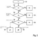
- the flowchart in FIG. 2 shows example method steps made during executing the proposed method for warning a driver of a motorcycle 1 .
- a decision (“? 1 ”) has to be taken regarding whether a critical traffic situation has occurred (step S 2 ). This decision may be made based on continuously or repetitively analysing signals from the sensors 17 . If no critical traffic situation is determined, no action (“na”) has to be initiated (step S 3 ).
- a further decision (“? 2 ”) has to be taken regarding whether a rider is aware of the critical situation (step S 4 ). This decision may be taken based for example on detecting specific reactions made by the rider such as manually actuating brakes and/or changing a steering angle. If the critical traffic situation has been recognised by the rider, no further action has to be taken (step S 5 ).
- ? 3 a further decision has to be taken regarding the manner and/or degree of inducing an acceleration change onto the motorcycle 1 for warning the driver.
- the above-mentioned situations A, B, C may be distinguished based on continuously or repetitively measuring a current lean angle of the motorcycle.
- an action A (“aA”) is initiated (step S 7 ).
- the front wheel brake 9 is actuated for inducing the acceleration change onto the motorcycle 1 .
- further measures such as actuating the rear wheel brake 13 , reducing an acceleration torque generated by the engine 5 and/or shifting the automated transmission 7 to a lower gear may be applied additionally.
- an action B (“aB”) is initiated (step S 8 ).
- the front wheel brake 9 is not actuated. Instead, only the rear wheel brake 13 is actuated for inducing the acceleration change onto the motorcycle 1 .
- further measures such as reducing the acceleration torque generated by the engine 5 and/or shifting the automatic transmission 7 to a lower gear may be applied additionally.
- na no action
Abstract
Description
-
- monitoring traffic situations based on signals from at least one sensor;
- upon detecting a critical traffic situation based on the signals from the at least one sensor, warning the driver by inducing an acceleration change onto the motorcycle;
- wherein a current lean angle of the motorcycle is monitored and a manner and/or degree of inducing the acceleration change onto the motorcycle is set taking into account the current lean angle of the motorcycle,
- wherein the acceleration change is induced by at least actuating a front wheel brake of the motorcycle in case the current lean angle is smaller than a predetermined first lean angle value,
- wherein the acceleration change is induced exclusively by one or more of actuating a rear wheel brake of the motorcycle, reducing an acceleration torque generated by an engine of the motorcycle and temporarily shifting an automated transmission of the motorcycle to a lower gear in case the current lean angle is bigger than the predetermined first lean angle and smaller than a predetermined second lean angle value, the first lean angle value being smaller than the second lean angle value,
- wherein no acceleration change is induced in case the current lean angle is bigger than the predetermined second lean angle.
-
- wherein the acceleration change is induced by at least actuating a front wheel brake of the motorcycle in case the current lean angle is smaller than a predetermined first lean angle value,
- wherein the acceleration change is induced exclusively by one or more of actuating a rear wheel brake of the motorcycle, reducing an acceleration torque generated by an engine of the motorcycle and temporarily shifting an automated transmission of the motorcycle to a lower gear in case the current lean angle is bigger than the predetermined first lean angle and smaller than a predetermined second lean angle value, the first lean angle value being smaller than the second lean angle value,
- wherein no acceleration change is induced in case the current lean angle is bigger than the predetermined second lean angle.
Claims (11)
Applications Claiming Priority (6)
| Application Number | Priority Date | Filing Date | Title |
|---|---|---|---|
| EP19170971.6 | 2019-04-25 | ||
| EP19170971.6A EP3730391A1 (en) | 2019-04-25 | 2019-04-25 | Method for warning a driver of a motorcycle as well as ride assistant controller and motorcycle implementing such method |
| EP19170971 | 2019-04-25 | ||
| EP20164781.5A EP3730392A1 (en) | 2019-04-25 | 2020-03-23 | Method for warning a driver of a motorcycle as well as ride assistant controller and motorcycle implementing such method |
| EP20164781 | 2020-03-23 | ||
| EP20164781.5 | 2020-03-23 |
Publications (2)
| Publication Number | Publication Date |
|---|---|
| US20200339144A1 US20200339144A1 (en) | 2020-10-29 |
| US11358609B2 true US11358609B2 (en) | 2022-06-14 |
Family
ID=66397006
Family Applications (1)
| Application Number | Title | Priority Date | Filing Date |
|---|---|---|---|
| US16/832,232 Active 2041-01-16 US11358609B2 (en) | 2019-04-25 | 2020-03-27 | Method for warning a driver of a motorcycle as well as ride assistant controller and motorcycle implementing such method |
Country Status (5)
| Country | Link |
|---|---|
| US (1) | US11358609B2 (en) |
| EP (2) | EP3730391A1 (en) |
| JP (1) | JP2021002328A (en) |
| CN (1) | CN111846045B (en) |
| DE (1) | DE102020108011A1 (en) |
Families Citing this family (1)
| Publication number | Priority date | Publication date | Assignee | Title |
|---|---|---|---|---|
| JP2021127069A (en) * | 2020-02-17 | 2021-09-02 | ロベルト・ボッシュ・ゲゼルシャフト・ミト・ベシュレンクテル・ハフツングRobert Bosch Gmbh | Control device and control method |
Citations (13)
| Publication number | Priority date | Publication date | Assignee | Title |
|---|---|---|---|---|
| US20040098185A1 (en) * | 2002-11-18 | 2004-05-20 | Wang Everett X. | Computerized automated dynamic control system for single-track vehicles |
| US20120239265A1 (en) | 2011-03-15 | 2012-09-20 | Fuji Jukogyo Kabushiki Kaisha | Vehicle driving support apparatus |
| WO2014064730A1 (en) * | 2012-10-22 | 2014-05-01 | 川崎重工業株式会社 | Regenerative brake control system for electric vehicle |
| DE102013200044A1 (en) | 2013-01-03 | 2014-07-03 | Robert Bosch Gmbh | Method for executing emergency brake of emergency braking system in two-wheeler in event of hazardous situation, involves detecting vehicle state variable, driver parameter and environment parameter within defined range of values |
| DE102015104547A1 (en) | 2015-03-26 | 2016-09-29 | Knorr-Bremse Systeme für Nutzfahrzeuge GmbH | Method for triggering an automatic emergency braking operation with a variable warning period |
| WO2018172871A1 (en) | 2017-03-21 | 2018-09-27 | ローベルト ボッシュ ゲゼルシャフト ミット ベシュレンクテル ハフツング | Control device and control method |
| WO2018172870A1 (en) | 2017-03-21 | 2018-09-27 | ローベルト ボッシュ ゲゼルシャフト ミット ベシュレンクテル ハフツング | Controller and control method |
| WO2018185577A1 (en) | 2017-04-06 | 2018-10-11 | ローベルト ボッシュ ゲゼルシャフト ミット ベシュレンクテル ハフツング | Control device, control method, and brake system |
| WO2018197965A1 (en) | 2017-04-17 | 2018-11-01 | ローベルト ボッシュ ゲゼルシャフト ミット ベシュレンクテル ハフツング | Controller, control method, and brake system |
| WO2019025886A1 (en) | 2017-08-02 | 2019-02-07 | ローベルト ボッシュ ゲゼルシャフト ミット ベシュレンクテル ハフツング | Control device, vehicle behavior control system, motorcycle, and control method |
| WO2019038609A1 (en) | 2017-08-02 | 2019-02-28 | ローベルト ボッシュ ゲゼルシャフト ミット ベシュレンクテル ハフツング | Control device, body behavior control system, motorcycle, and control method |
| US20190211919A1 (en) * | 2018-01-05 | 2019-07-11 | Sri International | Vehicle |
| US20200331460A1 (en) * | 2019-04-22 | 2020-10-22 | Robert Bosch Gmbh | Controller and control method |
Family Cites Families (2)
| Publication number | Priority date | Publication date | Assignee | Title |
|---|---|---|---|---|
| DE102011076633A1 (en) * | 2010-09-14 | 2012-03-15 | Robert Bosch Gmbh | Slope-dependent adaptation of a brake force control in single-track vehicles |
| JP6410509B2 (en) * | 2014-08-04 | 2018-10-24 | 株式会社エフ・シー・シー | Saddle riding |
-
2019
- 2019-04-25 EP EP19170971.6A patent/EP3730391A1/en not_active Withdrawn
-
2020
- 2020-03-23 EP EP20164781.5A patent/EP3730392A1/en active Pending
- 2020-03-24 DE DE102020108011.5A patent/DE102020108011A1/en active Pending
- 2020-03-27 US US16/832,232 patent/US11358609B2/en active Active
- 2020-04-15 JP JP2020072827A patent/JP2021002328A/en active Pending
- 2020-04-24 CN CN202010331321.5A patent/CN111846045B/en active Active
Patent Citations (13)
| Publication number | Priority date | Publication date | Assignee | Title |
|---|---|---|---|---|
| US20040098185A1 (en) * | 2002-11-18 | 2004-05-20 | Wang Everett X. | Computerized automated dynamic control system for single-track vehicles |
| US20120239265A1 (en) | 2011-03-15 | 2012-09-20 | Fuji Jukogyo Kabushiki Kaisha | Vehicle driving support apparatus |
| WO2014064730A1 (en) * | 2012-10-22 | 2014-05-01 | 川崎重工業株式会社 | Regenerative brake control system for electric vehicle |
| DE102013200044A1 (en) | 2013-01-03 | 2014-07-03 | Robert Bosch Gmbh | Method for executing emergency brake of emergency braking system in two-wheeler in event of hazardous situation, involves detecting vehicle state variable, driver parameter and environment parameter within defined range of values |
| DE102015104547A1 (en) | 2015-03-26 | 2016-09-29 | Knorr-Bremse Systeme für Nutzfahrzeuge GmbH | Method for triggering an automatic emergency braking operation with a variable warning period |
| WO2018172871A1 (en) | 2017-03-21 | 2018-09-27 | ローベルト ボッシュ ゲゼルシャフト ミット ベシュレンクテル ハフツング | Control device and control method |
| WO2018172870A1 (en) | 2017-03-21 | 2018-09-27 | ローベルト ボッシュ ゲゼルシャフト ミット ベシュレンクテル ハフツング | Controller and control method |
| WO2018185577A1 (en) | 2017-04-06 | 2018-10-11 | ローベルト ボッシュ ゲゼルシャフト ミット ベシュレンクテル ハフツング | Control device, control method, and brake system |
| WO2018197965A1 (en) | 2017-04-17 | 2018-11-01 | ローベルト ボッシュ ゲゼルシャフト ミット ベシュレンクテル ハフツング | Controller, control method, and brake system |
| WO2019025886A1 (en) | 2017-08-02 | 2019-02-07 | ローベルト ボッシュ ゲゼルシャフト ミット ベシュレンクテル ハフツング | Control device, vehicle behavior control system, motorcycle, and control method |
| WO2019038609A1 (en) | 2017-08-02 | 2019-02-28 | ローベルト ボッシュ ゲゼルシャフト ミット ベシュレンクテル ハフツング | Control device, body behavior control system, motorcycle, and control method |
| US20190211919A1 (en) * | 2018-01-05 | 2019-07-11 | Sri International | Vehicle |
| US20200331460A1 (en) * | 2019-04-22 | 2020-10-22 | Robert Bosch Gmbh | Controller and control method |
Also Published As
| Publication number | Publication date |
|---|---|
| EP3730391A1 (en) | 2020-10-28 |
| JP2021002328A (en) | 2021-01-07 |
| CN111846045B (en) | 2023-09-22 |
| CN111846045A (en) | 2020-10-30 |
| US20200339144A1 (en) | 2020-10-29 |
| DE102020108011A1 (en) | 2020-10-29 |
| EP3730392A1 (en) | 2020-10-28 |
Similar Documents
| Publication | Publication Date | Title |
|---|---|---|
| US20130191000A1 (en) | Stabilization of a vehicle combination | |
| JP5229341B2 (en) | Accelerator pedal misoperation device and program for accelerator pedal misoperation device | |
| US8508351B2 (en) | Method for warning the driver of a motor vehicle of increased risk of an accident | |
| JP5768891B2 (en) | Vehicle driving support system | |
| WO2013098996A1 (en) | Vehicle driving assistance device | |
| JP7261865B2 (en) | CONTROL DEVICE AND CONTROL METHOD FOR CONTROLLING MOTORCYCLE OPERATION | |
| US20200055500A1 (en) | Method for determining autonomous emergency braking, method for performing the emergency braking, and control device for a driving-dynamics system | |
| US11358609B2 (en) | Method for warning a driver of a motorcycle as well as ride assistant controller and motorcycle implementing such method | |
| US20230242100A1 (en) | Controller for straddle-type vehicle, rider-assistance system, and control method for straddle-type vehicle | |
| JPWO2020217133A1 (en) | Control device and control method | |
| US20230219412A1 (en) | Controller and control method | |
| JP7261866B2 (en) | CONTROL DEVICE AND CONTROL METHOD FOR CONTROLLING MOTORCYCLE OPERATION | |
| JP2022536324A (en) | Method and apparatus for performing autonomous braking in a two-wheeled vehicle | |
| US11047317B2 (en) | Method and device for influencing the engine control of a single-track motor vehicle | |
| US20190202493A1 (en) | Vehicle control apparatus | |
| US20230147892A1 (en) | Controller and control method | |
| JP2005022616A (en) | Traveling control device for vehicle | |
| JP4636286B2 (en) | Vehicle steering device | |
| JP4103478B2 (en) | Vehicle travel control device | |
| CN114269589A (en) | Vehicle operation method | |
| JP2005047389A (en) | Sloping road holding control device |
Legal Events
| Date | Code | Title | Description |
|---|---|---|---|
| FEPP | Fee payment procedure |
Free format text: ENTITY STATUS SET TO UNDISCOUNTED (ORIGINAL EVENT CODE: BIG.); ENTITY STATUS OF PATENT OWNER: LARGE ENTITY |
|
| AS | Assignment |
Owner name: KIDDAZZLE, INC., CANADA Free format text: ASSIGNMENT OF ASSIGNORS INTEREST;ASSIGNORS:GABER, STEPHANIE;GABER, JARED;REEL/FRAME:052780/0243 Effective date: 20200327 |
|
| STPP | Information on status: patent application and granting procedure in general |
Free format text: DOCKETED NEW CASE - READY FOR EXAMINATION |
|
| AS | Assignment |
Owner name: ROBERT BOSCH GMBH, GERMANY Free format text: ASSIGNMENT OF ASSIGNORS INTEREST;ASSIGNOR:OSHIDA, YUKI;REEL/FRAME:056804/0102 Effective date: 20210701 |
|
| STPP | Information on status: patent application and granting procedure in general |
Free format text: NOTICE OF ALLOWANCE MAILED -- APPLICATION RECEIVED IN OFFICE OF PUBLICATIONS |
|
| STPP | Information on status: patent application and granting procedure in general |
Free format text: PUBLICATIONS -- ISSUE FEE PAYMENT RECEIVED |
|
| STPP | Information on status: patent application and granting procedure in general |
Free format text: PUBLICATIONS -- ISSUE FEE PAYMENT VERIFIED |
|
| STCF | Information on status: patent grant |
Free format text: PATENTED CASE |