US11358522B2 - Lamp for vehicle - Google Patents
Lamp for vehicle Download PDFInfo
- Publication number
- US11358522B2 US11358522B2 US17/085,075 US202017085075A US11358522B2 US 11358522 B2 US11358522 B2 US 11358522B2 US 202017085075 A US202017085075 A US 202017085075A US 11358522 B2 US11358522 B2 US 11358522B2
- Authority
- US
- United States
- Prior art keywords
- light emitting
- color
- light
- lamp
- turn
- Prior art date
- Legal status (The legal status is an assumption and is not a legal conclusion. Google has not performed a legal analysis and makes no representation as to the accuracy of the status listed.)
- Active
Links
Images


Classifications
-
- F—MECHANICAL ENGINEERING; LIGHTING; HEATING; WEAPONS; BLASTING
- F21—LIGHTING
- F21S—NON-PORTABLE LIGHTING DEVICES; SYSTEMS THEREOF; VEHICLE LIGHTING DEVICES SPECIALLY ADAPTED FOR VEHICLE EXTERIORS
- F21S41/00—Illuminating devices specially adapted for vehicle exteriors, e.g. headlamps
- F21S41/60—Illuminating devices specially adapted for vehicle exteriors, e.g. headlamps characterised by a variable light distribution
- F21S41/65—Illuminating devices specially adapted for vehicle exteriors, e.g. headlamps characterised by a variable light distribution by acting on light sources
- F21S41/663—Illuminating devices specially adapted for vehicle exteriors, e.g. headlamps characterised by a variable light distribution by acting on light sources by switching light sources
-
- F—MECHANICAL ENGINEERING; LIGHTING; HEATING; WEAPONS; BLASTING
- F21—LIGHTING
- F21S—NON-PORTABLE LIGHTING DEVICES; SYSTEMS THEREOF; VEHICLE LIGHTING DEVICES SPECIALLY ADAPTED FOR VEHICLE EXTERIORS
- F21S43/00—Signalling devices specially adapted for vehicle exteriors, e.g. brake lamps, direction indicator lights or reversing lights
- F21S43/10—Signalling devices specially adapted for vehicle exteriors, e.g. brake lamps, direction indicator lights or reversing lights characterised by the light source
- F21S43/13—Signalling devices specially adapted for vehicle exteriors, e.g. brake lamps, direction indicator lights or reversing lights characterised by the light source characterised by the type of light source
- F21S43/15—Strips of light sources
-
- B—PERFORMING OPERATIONS; TRANSPORTING
- B60—VEHICLES IN GENERAL
- B60Q—ARRANGEMENT OF SIGNALLING OR LIGHTING DEVICES, THE MOUNTING OR SUPPORTING THEREOF OR CIRCUITS THEREFOR, FOR VEHICLES IN GENERAL
- B60Q1/00—Arrangement of optical signalling or lighting devices, the mounting or supporting thereof or circuits therefor
- B60Q1/26—Arrangement of optical signalling or lighting devices, the mounting or supporting thereof or circuits therefor the devices being primarily intended to indicate the vehicle, or parts thereof, or to give signals, to other traffic
- B60Q1/34—Arrangement of optical signalling or lighting devices, the mounting or supporting thereof or circuits therefor the devices being primarily intended to indicate the vehicle, or parts thereof, or to give signals, to other traffic for indicating change of drive direction
- B60Q1/38—Arrangement of optical signalling or lighting devices, the mounting or supporting thereof or circuits therefor the devices being primarily intended to indicate the vehicle, or parts thereof, or to give signals, to other traffic for indicating change of drive direction using immovably-mounted light sources, e.g. fixed flashing lamps
- B60Q1/381—Arrangement of optical signalling or lighting devices, the mounting or supporting thereof or circuits therefor the devices being primarily intended to indicate the vehicle, or parts thereof, or to give signals, to other traffic for indicating change of drive direction using immovably-mounted light sources, e.g. fixed flashing lamps with several light sources activated in sequence, e.g. to create a sweep effect
-
- B—PERFORMING OPERATIONS; TRANSPORTING
- B60—VEHICLES IN GENERAL
- B60Q—ARRANGEMENT OF SIGNALLING OR LIGHTING DEVICES, THE MOUNTING OR SUPPORTING THEREOF OR CIRCUITS THEREFOR, FOR VEHICLES IN GENERAL
- B60Q1/00—Arrangement of optical signalling or lighting devices, the mounting or supporting thereof or circuits therefor
- B60Q1/26—Arrangement of optical signalling or lighting devices, the mounting or supporting thereof or circuits therefor the devices being primarily intended to indicate the vehicle, or parts thereof, or to give signals, to other traffic
- B60Q1/48—Arrangement of optical signalling or lighting devices, the mounting or supporting thereof or circuits therefor the devices being primarily intended to indicate the vehicle, or parts thereof, or to give signals, to other traffic for parking purposes
-
- B—PERFORMING OPERATIONS; TRANSPORTING
- B60—VEHICLES IN GENERAL
- B60Q—ARRANGEMENT OF SIGNALLING OR LIGHTING DEVICES, THE MOUNTING OR SUPPORTING THEREOF OR CIRCUITS THEREFOR, FOR VEHICLES IN GENERAL
- B60Q11/00—Arrangement of monitoring devices for devices provided for in groups B60Q1/00 - B60Q9/00
- B60Q11/005—Arrangement of monitoring devices for devices provided for in groups B60Q1/00 - B60Q9/00 for lighting devices, e.g. indicating if lamps are burning or not
- B60Q11/007—Arrangement of monitoring devices for devices provided for in groups B60Q1/00 - B60Q9/00 for lighting devices, e.g. indicating if lamps are burning or not the lighting devices indicating change of drive direction
-
- F—MECHANICAL ENGINEERING; LIGHTING; HEATING; WEAPONS; BLASTING
- F21—LIGHTING
- F21S—NON-PORTABLE LIGHTING DEVICES; SYSTEMS THEREOF; VEHICLE LIGHTING DEVICES SPECIALLY ADAPTED FOR VEHICLE EXTERIORS
- F21S43/00—Signalling devices specially adapted for vehicle exteriors, e.g. brake lamps, direction indicator lights or reversing lights
- F21S43/10—Signalling devices specially adapted for vehicle exteriors, e.g. brake lamps, direction indicator lights or reversing lights characterised by the light source
- F21S43/13—Signalling devices specially adapted for vehicle exteriors, e.g. brake lamps, direction indicator lights or reversing lights characterised by the light source characterised by the type of light source
- F21S43/14—Light emitting diodes [LED]
-
- F—MECHANICAL ENGINEERING; LIGHTING; HEATING; WEAPONS; BLASTING
- F21—LIGHTING
- F21S—NON-PORTABLE LIGHTING DEVICES; SYSTEMS THEREOF; VEHICLE LIGHTING DEVICES SPECIALLY ADAPTED FOR VEHICLE EXTERIORS
- F21S43/00—Signalling devices specially adapted for vehicle exteriors, e.g. brake lamps, direction indicator lights or reversing lights
- F21S43/10—Signalling devices specially adapted for vehicle exteriors, e.g. brake lamps, direction indicator lights or reversing lights characterised by the light source
- F21S43/19—Attachment of light sources or lamp holders
-
- F—MECHANICAL ENGINEERING; LIGHTING; HEATING; WEAPONS; BLASTING
- F21—LIGHTING
- F21V—FUNCTIONAL FEATURES OR DETAILS OF LIGHTING DEVICES OR SYSTEMS THEREOF; STRUCTURAL COMBINATIONS OF LIGHTING DEVICES WITH OTHER ARTICLES, NOT OTHERWISE PROVIDED FOR
- F21V25/00—Safety devices structurally associated with lighting devices
- F21V25/02—Safety devices structurally associated with lighting devices coming into action when lighting device is disturbed, dismounted, or broken
-
- H—ELECTRICITY
- H05—ELECTRIC TECHNIQUES NOT OTHERWISE PROVIDED FOR
- H05B—ELECTRIC HEATING; ELECTRIC LIGHT SOURCES NOT OTHERWISE PROVIDED FOR; CIRCUIT ARRANGEMENTS FOR ELECTRIC LIGHT SOURCES, IN GENERAL
- H05B45/00—Circuit arrangements for operating light-emitting diodes [LED]
- H05B45/20—Controlling the colour of the light
-
- B—PERFORMING OPERATIONS; TRANSPORTING
- B60—VEHICLES IN GENERAL
- B60Q—ARRANGEMENT OF SIGNALLING OR LIGHTING DEVICES, THE MOUNTING OR SUPPORTING THEREOF OR CIRCUITS THEREFOR, FOR VEHICLES IN GENERAL
- B60Q2400/00—Special features or arrangements of exterior signal lamps for vehicles
- B60Q2400/20—Multi-color single source or LED matrix, e.g. yellow blinker and red brake lamp generated by single lamp
-
- B—PERFORMING OPERATIONS; TRANSPORTING
- B60—VEHICLES IN GENERAL
- B60Q—ARRANGEMENT OF SIGNALLING OR LIGHTING DEVICES, THE MOUNTING OR SUPPORTING THEREOF OR CIRCUITS THEREFOR, FOR VEHICLES IN GENERAL
- B60Q2400/00—Special features or arrangements of exterior signal lamps for vehicles
- B60Q2400/30—Daytime running lights [DRL], e.g. circuits or arrangements therefor
-
- F—MECHANICAL ENGINEERING; LIGHTING; HEATING; WEAPONS; BLASTING
- F21—LIGHTING
- F21W—INDEXING SCHEME ASSOCIATED WITH SUBCLASSES F21K, F21L, F21S and F21V, RELATING TO USES OR APPLICATIONS OF LIGHTING DEVICES OR SYSTEMS
- F21W2103/00—Exterior vehicle lighting devices for signalling purposes
- F21W2103/10—Position lights
-
- F—MECHANICAL ENGINEERING; LIGHTING; HEATING; WEAPONS; BLASTING
- F21—LIGHTING
- F21W—INDEXING SCHEME ASSOCIATED WITH SUBCLASSES F21K, F21L, F21S and F21V, RELATING TO USES OR APPLICATIONS OF LIGHTING DEVICES OR SYSTEMS
- F21W2103/00—Exterior vehicle lighting devices for signalling purposes
- F21W2103/20—Direction indicator lights
-
- F—MECHANICAL ENGINEERING; LIGHTING; HEATING; WEAPONS; BLASTING
- F21—LIGHTING
- F21W—INDEXING SCHEME ASSOCIATED WITH SUBCLASSES F21K, F21L, F21S and F21V, RELATING TO USES OR APPLICATIONS OF LIGHTING DEVICES OR SYSTEMS
- F21W2103/00—Exterior vehicle lighting devices for signalling purposes
- F21W2103/55—Daytime running lights [DRL]
-
- F—MECHANICAL ENGINEERING; LIGHTING; HEATING; WEAPONS; BLASTING
- F21—LIGHTING
- F21Y—INDEXING SCHEME ASSOCIATED WITH SUBCLASSES F21K, F21L, F21S and F21V, RELATING TO THE FORM OR THE KIND OF THE LIGHT SOURCES OR OF THE COLOUR OF THE LIGHT EMITTED
- F21Y2113/00—Combination of light sources
- F21Y2113/10—Combination of light sources of different colours
- F21Y2113/13—Combination of light sources of different colours comprising an assembly of point-like light sources
- F21Y2113/17—Combination of light sources of different colours comprising an assembly of point-like light sources forming a single encapsulated light source
Definitions
- the present disclosure relates to a lamp for a vehicle, and more specifically, to a lamp for a vehicle that allows a nearby vehicle or a pedestrian to easily recognize a driving state of the vehicle.
- a vehicle is equipped with various lamps having an illumination function for easily confirming an object positioned in the vicinity of the vehicle at low light conditions (e.g., nighttime driving), and a signaling function for informing a surrounding vehicle or pedestrians of a driving state of the vehicle.
- an illumination function for easily confirming an object positioned in the vicinity of the vehicle at low light conditions (e.g., nighttime driving)
- a signaling function for informing a surrounding vehicle or pedestrians of a driving state of the vehicle.
- the main purpose of head lamps and fog lamps is the illumination function
- the main purpose of position lamps, daytime running lamps, turn signal lamps, backup lamps, brake lamps, or the like is the signaling function.
- Each lamp is stipulated by laws and regulations for their installation standards and specifications so that each function may be fully utilized.
- aspects of the present disclosure provide a lamp for a vehicle that may be implemented to generate the light in different light emitting modes, and thereby any one of a plurality of functions may be performed alone or two or more functions may be performed simultaneously depending on operating status of the vehicle.
- a lamp for a vehicle may include a lamp unit including a plurality of light emitting areas arranged in a direction; a mode determination unit configured to determine a selected light emitting mode among a plurality of light emitting modes of the lamp unit; and a control unit configured to cause at least one of the plurality of light emitting areas to generate light having a first color or a second color based on the determined light emitting mode.
- the plurality of light emitting modes may include a first light emitting mode in which the light of the first color is generated from the plurality of light emitting areas; and a second light emitting mode in which the light generated from each of the plurality of light emitting areas is changed from the first color to the second color sequentially from a first side to a second side along the arrangement direction of the plurality of light emitting areas.
- the mode determination unit may be configured to determine that the second light emitting mode is selected in response to a turn signal being input during the first light emitting mode.
- a brightness of the light generated from the plurality of light emitting areas may be varied based on a function of the lamp unit.
- control unit may be configured to cause the plurality of light emitting areas to sequentially turn off the light of the first color, and to sequentially turn on the light of the second color.
- control unit may be configured to cause the lamp unit to operate in the second light emitting mode based on an operation signal that includes a turn-on period and a turn-off period repeated with a predetermined period.
- the control unit may be configured to cause the lamp unit to operate in the second light emitting mode based on an operation signal that includes a turn-on period and a turn-off period repeated with a predetermined period.
- the second light emitting mode during a first time segment of the turn-on period, the light of the first color may be turned off and the light of the second color may be turned on sequentially from the plurality of light emitting areas.
- the light of the second color may be generated from the plurality of light emitting areas.
- the turn-off period the light of the first color may be generated from the plurality of light emitting areas.
- the plurality of light emitting modes may further comprise a third light emitting mode in which the light of the second color is sequentially generated from the plurality of light emitting areas, and the control unit may be configured to simultaneously turn off the plurality of light emitting areas in which the light in accordance with the first light emitting mode is generated, and to subsequently operate the plurality of light emitting areas in the third light emitting mode.
- the mode determination unit may be configured to determine that the third light emitting mode is selected in response to a turn signal being input during the first light emitting mode.
- either one of the second light emitting mode or the third light emitting mode may be selected based on a brightness of the light generated from the plurality of light emitting areas.
- the lamp unit may comprise a plurality of light emitting units that form each of the plurality of light emitting areas.
- Each of the plurality of light emitting units may include a first light source to generate the light of the first color; and a second light source to generate the light of the second color.
- the first light source of the first color may be sequentially turned off, and the second light source of the second color may be sequentially turned on.
- a time point when the first light source of the first color is turned off may correspond to a time point when the second light source of the second color is turned on.
- the first light source of the first color may be sequentially turned off, and the second light source of the second color may be sequentially turned on. Either one of a time point when the first light source of the first color is turned off and a time point when the second light source of the second color is turned on may be earlier than the other. A delay time between the time point when the first light source of the first color is turned off and the time point when the second light source of the second color is turned on may be equal to or less than about 100 ms.
- a failure detection unit may be further provided to detect a failure of the lamp unit.
- the control unit may be configured to cause the plurality of light emitting areas to generate the light with one of the first color or the second color in unison.
- the control unit may be configured to cause the plurality of light emitting areas to alternately generate the light of the first color in unison and the light of the second color in unison.
- the control unit may be configured to cause the plurality of the light emitting areas to generate the light of the first color in unison.
- the first color may be white, which is for a function of a position lamp or a daytime running lamp
- the second color may be yellow, which is for a function of a turn signal lamp.
- a method of operating a lamp for vehicle comprising a plurality of light emitting areas each configured to generate light having a first color or a second color.
- the method may include generating the light of the first color in each of the plurality of light emitting areas; during a first time segment of a turn-on period, changing the light in each of the plurality of light emitting areas from the first color to the second color sequentially from a first side to a second side along an arrangement direction of the plurality of light emitting areas; during a second time segment of the turn-on period, which follows the first time segment of the turn-on period, generating the light of the second color in each of the plurality of light emitting areas; and changing the light in each of the plurality of light emitting areas from the second color to the first color simultaneously and sustaining the light of the first color during a turn-off period.
- the first time segment of the turn-on period may be initiated in response to a turn signal being input, and thereafter, the first time segment of the turn-
- the method may further include, in response to detecting a failure of the lamp while the turn signal is input, alternately generating the light of the second color in unison during the turn-on period and the light of the first color in unison during the turn-off period from the plurality of light emitting areas.
- the light with one of the first color or the second color may be generated in unison from the plurality of light emitting areas until the failure is resolved.
- the light of the first color may be generated in unison from the plurality of light emitting areas until the failure is resolved.
- a lamp for a vehicle has one or more of the following benefits. It may be implemented to generate the light in different light emitting modes, such that any one of a plurality of functions is performed alone or two or more functions are performed simultaneously depending on operation status of the vehicle. Therefore, it is possible to implement more various functions. In addition, compared to the case of having each lamp for each function, the installation space may be reduced, and thus space utilization may be improved.
- the benefits of the present disclosure are not limited to the above-mentioned benefits, and other benefits not mentioned may be clearly understood by a person skilled in the art from the claims.
- FIG. 1 is a block diagram showing the configuration of a lamp for a vehicle according to an exemplary embodiment of the present disclosure
- FIG. 2 is a perspective view showing a lamp unit according to the exemplary embodiment of the present disclosure
- FIG. 3 is a front view showing the lamp unit according to the exemplary embodiment of the present disclosure.
- FIG. 4 is an exploded perspective view showing the lamp unit according to the exemplary embodiment of the present disclosure.
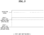
- FIG. 5 is a graph showing a timing chart of a first light emitting mode according to the exemplary embodiment of the present disclosure
- FIG. 6 is a schematic diagram showing an operation process of the first light emitting mode according to the exemplary embodiment of the present disclosure
- FIG. 7 is a graph showing a timing chart of a second light emitting mode according to the exemplary embodiment of the present disclosure.
- FIG. 8 is a schematic diagram showing an operation process of the second light emitting mode according to the exemplary embodiment of the present disclosure.
- FIG. 9 is a graph showing a timing chart of a third light emitting mode according to the exemplary embodiment of the present disclosure.
- FIG. 10 is a schematic diagram showing an operation process of the third light emitting mode according to the exemplary embodiment of the present disclosure.
- FIG. 11 is a graph showing a timing chart of a fourth light emitting mode according to the exemplary embodiment of the present disclosure.
- FIG. 12 is a schematic diagram showing an operation process of the fourth light emitting mode according to the exemplary embodiment of the present disclosure.
- FIG. 13 is a graph showing a timing chart of a fifth light emitting mode according to the exemplary embodiment of the present disclosure.
- FIG. 14 is a schematic diagram showing an operation process of the fifth light emitting mode according to the exemplary embodiment of the present disclosure.
- Exemplary embodiments of the disclosure are described herein with reference to plan and cross-section illustrations that are schematic illustrations of idealized exemplary embodiments of the disclosure. As such, variations from the shapes of the illustrations as a result, for example, of manufacturing techniques and/or tolerances, are to be expected. Thus, exemplary embodiments of the disclosure should not be construed as limited to the particular shapes of regions illustrated herein but are to include deviations in shapes that result, for example, from manufacturing. In the drawings, respective components may be enlarged or reduced in size for convenience of explanation.
- FIG. 1 is a block diagram showing the configuration of a lamp for a vehicle according to an exemplary embodiment of the present disclosure.
- a lamp 1 for a vehicle according to an exemplary embodiment of the present disclosure may include a lamp unit 100 , a mode determination unit 200 , and a control unit 300 .
- the lamp 1 for the vehicle may be used as a function such as a position lamp, a daytime running lamp, a turn signal lamp, or the like that may inform a surrounding vehicle or a pedestrian of a driving state of the vehicle.
- the lamp 1 for the vehicle of the present disclosure may be used for one of the functions described above or may be used together for two or more functions.
- an example will be described in which the lamp 1 for the vehicle is used for two or more functions, such as a position lamp and a turn signal lamp, or a daytime running lamp and a turn signal lamp.
- the lamp unit 100 may generate light that is suitable for the functions of the lamp 1 for the vehicle of the present disclosure.
- a color, a brightness, an emission region, or the like of the light generated by the lamp unit 100 may be varied depending on the functions of the lamp 1 for the vehicle of the present disclosure.
- FIG. 2 is a perspective view showing the lamp unit according to the exemplary embodiment of the present disclosure.
- FIG. 3 is a front view showing the lamp unit according to the exemplary embodiment of the present disclosure.
- FIG. 4 is an exploded perspective view showing the lamp unit according to the exemplary embodiment of the present disclosure.
- the lamp unit 100 may include a plurality of light emitting units 110 , 120 , and 130 arranged in a direction.
- the plurality of light emitting units 110 , 120 , and 130 may be accommodated in a space formed by a lamp housing 100 a and a lens unit 100 b coupled to the lamp housing 100 a , and at least one of the plurality of light emitting units 110 , 120 , and 130 may generate light based on a required lighting image.
- the plurality of light emitting units 110 , 120 , and 130 may be arranged in a left-right direction, that is, a vehicle width direction or a lateral direction.
- the plurality of light emitting units 110 , 120 , and 130 will be referred to as a first light emitting unit 110 , a second light emitting unit 120 , and a third light emitting unit 130 , respectively, in a direction from the inboard to the outboard of the vehicle.
- the light emitting area A of the lamp unit 100 may correspond to an area in which an emission surface 100 c of the lens unit 100 b through which the light is emitted from the lamp unit 100 is formed, and may include a plurality of light emitting areas A 1 , A 2 , and A 3 formed by each of the plurality of light emitting units 110 , 120 , and 130 .
- the plurality of light emitting areas A 1 , A 2 , and A 3 formed by the first to third light emitting units 110 , 120 , and 130 , respectively, will be referred to as a first light emitting area A 1 , a second light emitting area A 2 , and a third light emitting area A 3 .
- the plurality of light emitting units 110 , 120 , and 130 may be formed in three to form three light emitting areas.
- the present disclosure is not limited thereto, and the number of light emitting units may be varied depending on a layout of the lamp unit 100 or on design perspectives.
- Each of the plurality of light emitting units 110 , 120 , and 130 may include at least one first light source 141 for generating light of a first color and at least one second light source 142 for generating light of a second color.
- the number or position of the light sources included in each light emitting unit may vary depending on a size or shape of a light emitting area formed by each light emitting unit.
- the first light source 141 of the first color and the second light source 142 of the second color may form one light source group, and each light source group may be installed on a substrate 143 mounted on a support 144 such as a heat sink.
- the number of light source groups included in each of the first to third light emitting units 110 , 120 , and 130 decreases from the first light emitting unit 110 to the third light emitting unit 130 .
- the present disclosure is not limited thereto, and the number of light source groups included in each of the first to third light emitting units 110 , 120 , and 130 may vary depending on a size or shape of each of the first to third light emitting areas A 1 , A 2 , and A 3 .
- each of the plurality of light emitting units 110 , 120 , and 130 may include the first light source 141 of the first color and the second light source 142 of the second color, and thus to the two light sources 141 and 142 may be used together for the functions described above.
- the plurality of light emitting units 110 , 120 , and 130 may generate at least one of the first color or the second color based on the function of the lamp 1 for the vehicle of the present disclosure.
- the first color may be white, which is suitable for a function of a position lamp or a daytime running lamp
- the second color may be yellow, which is suitable for a function of a turn signal lamp.
- the present disclosure is not limited thereto, and the first color and the second color may be variously changed based on the function of the lamp 1 for the vehicle of the present disclosure.
- the lamp unit 100 may be operated in any one of a plurality of light emitting modes.
- light having the first color or the second color may be generated from at least one of the plurality of light emitting units 110 , 120 , and 130 in accordance with each light emitting mode.
- the plurality of light emitting modes may include, for example, a first light emitting mode, a second light emitting mode, and a third light emitting mode.
- first light emitting mode light with the first color may be collectively generated from the plurality of light emitting units 110 , 120 , and 130 .
- second light emitting mode which may follow the first light emitting mode, light generated from each of the plurality of light emitting units 110 , 120 , and 130 may be sequentially changed from the first color to the second color.
- the light corresponding to the first light emitting mode may be turned off from the plurality of light emitting units 110 , 120 , and 130 in unison, and light with the second color may be generated sequentially from each of the plurality of light emitting units 110 , 120 , and 130 along the arrangement direction thereof.
- the first light emitting mode may be for a function of a position lamp or a function of a daytime running lamp
- the second light emitting mode and the third light emitting mode may be for a function of a turn signal lamp.
- the first to third light emitting modes are described in detail as follows.
- the first light emitting mode may be used as a position lamp function or a daytime running lamp function, and the light of the first color may be collectively generated from the plurality of light emitting units 110 , 120 , and 130 .
- the brightness of the light generated from the plurality of light emitting units 110 , 120 , and 130 may be varied based on the function of the lamp 1 for the vehicle of the present disclosure. For example, compared to the case where the lamp 1 for the vehicle of the present disclosure is used for a function of a position lamp, in the case where it is used for a function of a daytime running lamp, the brightness of the light generated from the plurality of light emitting units 110 , 120 , and 130 may be greater. This is to ensure visibility of the daytime running lamp, since the daytime running lamp is typically used during the daytime when it is more difficult to ensure visibility, whereas the position lamp is typically used during the nighttime.
- the second light emitting mode and the third light emitting mode may be used for when a turn signal is input by a driver or a sensor installed in a vehicle while the lamp unit 100 is in the first light emitting mode.
- the second light emitting mode and the third light emitting mode may be determined based on the function of the lamp 1 for the vehicle of the present disclosure.
- the position lamp since the position lamp may mainly serve to inform the presence of the vehicle and the width thereof at night or in low light conditions, it needs to be illuminated constantly or substantially constantly.
- the daytime running lamp may be mainly used for allowing the vehicle to be more easily recognized when the weather is cloudy or foggy during the daytime, and it may be not be required to be constantly illuminated, unlike the position lamp. Therefore, different light emitting modes may be used for the position lamp and the daytime running lamp.
- the second light emitting mode may be used when a turn signal is input while the lamp 1 for the vehicle of the present disclosure is being used as a function of a position lamp.
- the second light emitting mode may be understood as a mode in which a function of a position lamp and a function of a turn signal lamp are simultaneously performed in response to the turn signal being input.
- the light generated from each of the plurality of light emitting units 110 , 120 , and 130 may be changed from the first color to the second color sequentially from a first side to a second side along the arrangement direction of the plurality of light emitting units 110 , 120 , and 130 .
- yellow light may be generated in the order of the first light emitting part 110 , the second light emitting part 120 , and the third light emitting part 130 , such that as a whole, the white light is sequentially turned off, and the yellow light is sequentially turned on.
- the position lamp function and the turn signal lamp function may be performed simultaneously.
- the first light emitting area A 1 of a light emitting unit that generates the yellow light first among the first to third light emitting units 110 , 120 , and 130 may have an area of at least 24 cm 2 .
- This is to allow nearby vehicles or pedestrians to easily recognize that the function of the turn signal lamp is being performed.
- a light emitting area formed by the light emitting unit that first generates the light may have an area of at least 24 cm 2 .
- the third light emitting mode may be used when a turn signal is input while the lamp 1 for the vehicle of the present disclosure is being used as a function of a daytime running lamp. Accordingly, in the third light emitting mode, the lamp 1 for the vehicle may be used for a function of a turn signal lamp instead of the daytime running lamp in response to the turn signal being input.
- the third light emitting mode when the turn signal is input while the lamp unit 100 is operating in the first light emitting mode and the light of the first color is collectively generated from the plurality of light emitting units 110 , 120 , and 130 , after the light of the first color is turned off simultaneously, light of the second color may be generated sequentially from each of the plurality of light emitting units 110 , 120 , and 130 from the first side to the second side along the arrangement direction thereof.
- the yellow light may be generated in the order of the first light emitting unit 110 , the second light emitting unit 120 , and the third light emitting unit 130 , to allow the function of the turn signal lamp to be performed.
- the mode determination unit 200 may determine the light emitting mode of the lamp unit 100 and transmit the information regarding the determined light emitting mode to the control unit 300 . For example, when an operation signal of the position lamp or daytime running lamp is input, the mode determination unit 200 may determine it as the first light emitting mode. In addition, when a turn signal is input in the first light emitting mode, the mode determination unit 200 may determine whether to transmit the information corresponding to the second light emitting mode or to the third light emitting mode. In particular, the second light emitting mode and the third light emitting mode may be determined based on for which function the lamp 1 for the vehicle of the present disclosure is being used in the first light emitting mode.
- the control unit 300 may be configured to control an operation of the plurality of light emitting units 110 , 120 , and 130 based on the light emitting mode determined by the mode determination unit 200 .
- FIG. 5 is a graph showing a timing chart of the first light emitting mode according to the exemplary embodiment of the present disclosure.
- the control unit 300 when an operation signal of the position lamp or daytime running lamp is input, the control unit 300 according to the exemplary embodiment of the present disclosure may be configured to turn on the light source of the first color included in each of the first to third light emitting units 110 , 120 , and 130 in the first light emitting mode, and turn off the light source of the second color, thereby enabling the light of the first color to be generated in the first to third light emitting areas A 1 , A 2 , and A 3 in unison as shown in FIG. 6 .
- FIG. 7 is a graph showing a timing chart of the second light emitting mode according to the exemplary embodiment of the present disclosure.
- the control unit 300 in response to a turn signal being input during the first light emitting mode operating as the position lamp function, the control unit 300 according to the exemplary embodiment of the present disclosure may be configured to cause the light of the first color to be sequentially turned off and the light of the second color to be sequentially turned on going from a first side to a second side in the arrangement direction based on the operation signal.
- the operation signal may include a turn-on period T on and a turn-off period T off , which are repeated with a predetermined period T. Accordingly, the functions of the position lamp and turn signal lamp may be performed simultaneously.
- the light of the first color in a state in which the light of the first color is generated from the first to third light emitting areas A 1 , A 2 , and A 3 as shown in FIG. 8 , the light of the first color may be sequentially turned off from the first light emitting area A 1 to the third light emitting area A 3 , and the light of the second color may be sequentially turned on.
- the light generated from the first to third light emitting units 110 , 120 , and 130 may be sequentially changed from the first color to the second color at a predetermined time interval t during the first time segment T 1 of the turn-on period T on , and after the first time segment T 1 , the second color may be maintained for the second time segment T 2 . Subsequently, the light of the first color may be generated from the first to third light emitting units 110 , 120 , and 130 during the turn-off period T off . Accordingly, the functions of the position lamp and the turn signal lamp may be performed simultaneously.
- a time point of turning off the light of the first color and a time point of turning on the light of the second color may or may not correspond to each other.
- the time point of turning off the light having the first color and the time point of turning on the light having the second color are different from each other, either one of the time point of turning off the light having the first color and the time point of turning on the light having the second color may be earlier than the other, and a delay time between the two time points may be greater than 0 and equal to or less than about 100 ms.
- the delay time between the time point of turning off the light having the first color and the time point of turning on the light having the second color corresponds to a time period during which a surrounding vehicle or a pedestrian may recognize the change of color and during which a lighting image may be smoothly transitioned.
- FIG. 9 is a graph showing a timing chart of the third light emitting mode according to the exemplary embodiment of the present disclosure.
- the control unit 300 in response to a turn signal being input during the first light emitting mode operating as the daytime running lamp, the control unit 300 according to the exemplary embodiment of the present disclosure may be configured to turn off the first to third light emitting units 110 , 120 , and 130 simultaneously, and subsequently, to cause the first to third light emitting units 110 , 120 , and 130 to be sequentially turned on such that the light of the second color is generated from the first side to the second side along the arrangement direction based on the operation signal.
- the operation signal may include the turn-on period T on and the turn-off period T off that are repeated with a predetermined period T. Accordingly, the function of the turn signal lamp may be performed instead of the daytime running lamp.
- the light of the first color in a state in which the light of the first color is generated from the first to third light emitting areas A 1 , A 2 , and A 3 as shown in FIG. 10 , when the turn signal is input, the light of the first color may be turned off together, and subsequently, the light of the second color may be sequentially turned on from the first light emitting area A 1 to the third light emitting area A 3 .
- the light of the second color may be sequentially generated from the first to third light emitting units 110 , 120 , and 130 at a predetermined time interval t during the first time segment T 1 .
- the second color may be maintained for the second time segment T 2 .
- the first to third light emitting units 110 , 120 , and 130 may be turned off together.
- the control unit 300 may be configured to operate the lamp unit 100 in a light emitting mode different from the first to third light emitting modes described above (e.g., a fourth light emitting mode).
- the lamp 1 for the vehicle of the present disclosure may further include a failure detection unit 400 for detecting a failure of the lamp unit 100 due to various causes such as described above.
- the sequential illumination of the first to third light emitting units 110 , 120 , and 130 may be used for the turn signal lamp. Therefore, an example will be presented in which the failure detection unit 400 detects a light source failure or a control circuit malfunction for an operation of the turn signal lamp based on an electric current or a voltage.
- the control unit 300 may be configured to determine that normal sequential turn-off or sequential turn-on is unavailable, and may be configured to cause light having at least one of the first color or the second color to be generated in unison from the first to third light emitting units 110 , 120 , and 130 .
- the control unit 300 may be configured to cause the first to third light emitting units 110 , 120 , and 130 to alternately generate the light of the first color and the light of the second color based on the turn-on period T on and the turn-off period T off of the operation signal as shown in FIGS. 11 and 12 .
- the control unit 300 may be configured to cause the light of the first color and the light of the second color to be alternately generated based on the operation signal. Therefore, the occurrence of a vehicle accident may be prevented due to the notifying nearby vehicles or pedestrians of a turn direction of the vehicle while allowing a failure to be recognized.
- FIGS. 11 and 12 were described as an example in which the lamp unit 100 is operated in the fourth light emitting mode in response to the occurrence of a failure.
- the present disclosure is not limited thereto, and the fourth light emitting mode may be selected by a driver.
- the control unit 300 may be configured to cause the first to third light emitting units 110 , 120 , and 130 to generate the light of the first color in unison from a time point when the light source failure is detected until the failure is resolved (e.g., a fifth light emitting mode).
- FIGS. 13 and 14 an example is described in which when a failure of the light source occurs, the light of the first color is generated in unison from the first to third light emitting units 110 , 120 and 130 until the failure is resolved.
- the present disclosure is not limited thereto, and even when the light source failure occurs, it may be operated in the fourth light emitting mode described above.
- the lamp 1 for the vehicle of the present disclosure since it may be used for two or more functions, vehicle accidents may be presented due to the different light emitting modes enabled depending on whether the light is required to be constantly on or not.
Abstract
Description
Claims (19)
Applications Claiming Priority (2)
| Application Number | Priority Date | Filing Date | Title |
|---|---|---|---|
| KR10-2019-0160767 | 2019-12-05 | ||
| KR1020190160767A KR20210070698A (en) | 2019-12-05 | 2019-12-05 | Lamp for vehicle |
Publications (2)
| Publication Number | Publication Date |
|---|---|
| US20210170940A1 US20210170940A1 (en) | 2021-06-10 |
| US11358522B2 true US11358522B2 (en) | 2022-06-14 |
Family
ID=76210784
Family Applications (1)
| Application Number | Title | Priority Date | Filing Date |
|---|---|---|---|
| US17/085,075 Active US11358522B2 (en) | 2019-12-05 | 2020-10-30 | Lamp for vehicle |
Country Status (2)
| Country | Link |
|---|---|
| US (1) | US11358522B2 (en) |
| KR (1) | KR20210070698A (en) |
Citations (14)
| Publication number | Priority date | Publication date | Assignee | Title |
|---|---|---|---|---|
| US20050134447A1 (en) * | 2003-12-22 | 2005-06-23 | Wen-Wei Su | Automobile indicator |
| US20050269480A1 (en) * | 2003-10-23 | 2005-12-08 | Ford Timothy D | Multifunction multi-spectrum signalling device |
| JP2011195032A (en) * | 2010-03-19 | 2011-10-06 | Panasonic Corp | Device and method for monitoring rear of vehicle |
| US20120242227A1 (en) * | 2011-03-22 | 2012-09-27 | Bob Miller | Lighting device and method of transitioning color outputs |
| DE102013207587A1 (en) * | 2012-05-03 | 2013-11-14 | GM Global Technology Operations LLC (n. d. Gesetzen des Staates Delaware) | Autonomous vehicle positioning system for determining position of car for e.g. traffic management application, has host vehicle control unit for utilizing signal reception properties at reference points associated with broadcast messages |
| US20140361738A1 (en) * | 2013-06-05 | 2014-12-11 | Samsung Electronics Co., Ltd. | Method of generating load variation for detecting wireless power receiving unit in wireless charging, and wireless power receiving unit |
| US20150296599A1 (en) * | 2014-04-11 | 2015-10-15 | Wireless Environment, Llc | Modular coordinated lighting system |
| US20180051869A1 (en) * | 2016-08-22 | 2018-02-22 | Barco Lighting Systems, Inc. | Theatre light apparatus and method incorporating a plurality of light sources with anti-collision |
| US20180279454A1 (en) * | 2017-03-24 | 2018-09-27 | Panasonic Intellectual Property Management Co., Ltd. | Illumination apparatus and illumination system |
| US20190077427A1 (en) * | 2016-05-12 | 2019-03-14 | Kyosan Electric Mfg. Co., Ltd. | On-board system and train occupancy range calculation method |
| WO2019082615A1 (en) * | 2017-10-23 | 2019-05-02 | 株式会社小糸製作所 | Vehicle light fixture |
| WO2019155832A1 (en) * | 2018-02-08 | 2019-08-15 | 株式会社小糸製作所 | Vehicular lamp |
| EP3421328B1 (en) * | 2017-05-30 | 2019-10-02 | LG Electronics Inc. | Parking assistance system |
| EP3799533A1 (en) * | 2019-09-27 | 2021-03-31 | Helvar Oy Ab | Self-adaptive lighting control |
Family Cites Families (1)
| Publication number | Priority date | Publication date | Assignee | Title |
|---|---|---|---|---|
| KR20170082670A (en) | 2016-01-06 | 2017-07-17 | 엘지전자 주식회사 | Lamp for vehicle and Vehicle including the same |
-
2019
- 2019-12-05 KR KR1020190160767A patent/KR20210070698A/en unknown
-
2020
- 2020-10-30 US US17/085,075 patent/US11358522B2/en active Active
Patent Citations (14)
| Publication number | Priority date | Publication date | Assignee | Title |
|---|---|---|---|---|
| US20050269480A1 (en) * | 2003-10-23 | 2005-12-08 | Ford Timothy D | Multifunction multi-spectrum signalling device |
| US20050134447A1 (en) * | 2003-12-22 | 2005-06-23 | Wen-Wei Su | Automobile indicator |
| JP2011195032A (en) * | 2010-03-19 | 2011-10-06 | Panasonic Corp | Device and method for monitoring rear of vehicle |
| US20120242227A1 (en) * | 2011-03-22 | 2012-09-27 | Bob Miller | Lighting device and method of transitioning color outputs |
| DE102013207587A1 (en) * | 2012-05-03 | 2013-11-14 | GM Global Technology Operations LLC (n. d. Gesetzen des Staates Delaware) | Autonomous vehicle positioning system for determining position of car for e.g. traffic management application, has host vehicle control unit for utilizing signal reception properties at reference points associated with broadcast messages |
| US20140361738A1 (en) * | 2013-06-05 | 2014-12-11 | Samsung Electronics Co., Ltd. | Method of generating load variation for detecting wireless power receiving unit in wireless charging, and wireless power receiving unit |
| US20150296599A1 (en) * | 2014-04-11 | 2015-10-15 | Wireless Environment, Llc | Modular coordinated lighting system |
| US20190077427A1 (en) * | 2016-05-12 | 2019-03-14 | Kyosan Electric Mfg. Co., Ltd. | On-board system and train occupancy range calculation method |
| US20180051869A1 (en) * | 2016-08-22 | 2018-02-22 | Barco Lighting Systems, Inc. | Theatre light apparatus and method incorporating a plurality of light sources with anti-collision |
| US20180279454A1 (en) * | 2017-03-24 | 2018-09-27 | Panasonic Intellectual Property Management Co., Ltd. | Illumination apparatus and illumination system |
| EP3421328B1 (en) * | 2017-05-30 | 2019-10-02 | LG Electronics Inc. | Parking assistance system |
| WO2019082615A1 (en) * | 2017-10-23 | 2019-05-02 | 株式会社小糸製作所 | Vehicle light fixture |
| WO2019155832A1 (en) * | 2018-02-08 | 2019-08-15 | 株式会社小糸製作所 | Vehicular lamp |
| EP3799533A1 (en) * | 2019-09-27 | 2021-03-31 | Helvar Oy Ab | Self-adaptive lighting control |
Also Published As
| Publication number | Publication date |
|---|---|
| KR20210070698A (en) | 2021-06-15 |
| US20210170940A1 (en) | 2021-06-10 |
Similar Documents
| Publication | Publication Date | Title |
|---|---|---|
| EP3369622B1 (en) | Vehicle with an illumination device | |
| US9550448B2 (en) | Light distribution control method and light distribution control device for a vehicular headlamp | |
| EP2543542B1 (en) | Automotive turn signal lamp and controlling method for the same | |
| US7019463B2 (en) | Daytime running light module and system | |
| US11014575B2 (en) | Vehicular illumination device, vehicle system and vehicle | |
| WO2017073632A1 (en) | Vehicular illumination device, vehicle system, and vehicle | |
| US9260053B2 (en) | Automotive headlamp system and method of controlling the same | |
| US9889792B2 (en) | Automotive lamp | |
| EP3178698A1 (en) | Automotive lamp and method of controlling the same | |
| CN210035343U (en) | Vehicle lamp | |
| CN111278680B (en) | Turning back and turning back taillight and unmanned method using same | |
| KR20140110593A (en) | Vehicle having lamp | |
| KR20130000203A (en) | Automotive lamp | |
| CN110997407A (en) | Autonomous vehicle | |
| JP5809701B2 (en) | Lighting system | |
| US11358522B2 (en) | Lamp for vehicle | |
| JP2013184521A (en) | Vehicular lighting system and control system thereof | |
| EP2666671B1 (en) | Automotive headlamp system and method of controlling the same | |
| JP2020032745A (en) | Vehicular lighting fixture | |
| CN209938434U (en) | Vehicle lamp system and vehicle | |
| US20210048162A1 (en) | Headlamp for vehicle and method for controlling the same | |
| JP2013189105A (en) | In-vehicle lighting device | |
| KR101105133B1 (en) | A rear assist lighting device for vehicle | |
| US20230122166A1 (en) | Light distribution control device | |
| KR101656685B1 (en) | Apparatus and method for controlling of automotive lamp |
Legal Events
| Date | Code | Title | Description |
|---|---|---|---|
| AS | Assignment |
Owner name: SL CORPORATION, KOREA, REPUBLIC OF Free format text: ASSIGNMENT OF ASSIGNORS INTEREST;ASSIGNORS:KWON, MIN JAE;JEONG, SEUNG HO;CHOI, GYEONG HO;REEL/FRAME:054225/0433 Effective date: 20201028 |
|
| FEPP | Fee payment procedure |
Free format text: ENTITY STATUS SET TO UNDISCOUNTED (ORIGINAL EVENT CODE: BIG.); ENTITY STATUS OF PATENT OWNER: LARGE ENTITY |
|
| STPP | Information on status: patent application and granting procedure in general |
Free format text: APPLICATION DISPATCHED FROM PREEXAM, NOT YET DOCKETED |
|
| STPP | Information on status: patent application and granting procedure in general |
Free format text: DOCKETED NEW CASE - READY FOR EXAMINATION |
|
| STPP | Information on status: patent application and granting procedure in general |
Free format text: NON FINAL ACTION MAILED |
|
| STPP | Information on status: patent application and granting procedure in general |
Free format text: RESPONSE TO NON-FINAL OFFICE ACTION ENTERED AND FORWARDED TO EXAMINER |
|
| STPP | Information on status: patent application and granting procedure in general |
Free format text: NOTICE OF ALLOWANCE MAILED -- APPLICATION RECEIVED IN OFFICE OF PUBLICATIONS |
|
| STPP | Information on status: patent application and granting procedure in general |
Free format text: PUBLICATIONS -- ISSUE FEE PAYMENT RECEIVED |
|
| STPP | Information on status: patent application and granting procedure in general |
Free format text: PUBLICATIONS -- ISSUE FEE PAYMENT VERIFIED |
|
| STCF | Information on status: patent grant |
Free format text: PATENTED CASE |