US11351909B2 - Resilient cover clip - Google Patents
Resilient cover clip Download PDFInfo
- Publication number
- US11351909B2 US11351909B2 US17/005,826 US202017005826A US11351909B2 US 11351909 B2 US11351909 B2 US 11351909B2 US 202017005826 A US202017005826 A US 202017005826A US 11351909 B2 US11351909 B2 US 11351909B2
- Authority
- US
- United States
- Prior art keywords
- channel
- arm
- cover
- clip
- tab
- Prior art date
- Legal status (The legal status is an assumption and is not a legal conclusion. Google has not performed a legal analysis and makes no representation as to the accuracy of the status listed.)
- Active, expires
Links
- 239000000463 material Substances 0.000 claims description 20
- 238000003780 insertion Methods 0.000 claims description 4
- 230000037431 insertion Effects 0.000 claims description 4
- 230000003247 decreasing effect Effects 0.000 claims description 3
- 230000000717 retained effect Effects 0.000 claims description 3
- 239000012858 resilient material Substances 0.000 claims description 2
- 239000011152 fibreglass Substances 0.000 description 17
- 241000785736 Pholis crassispina Species 0.000 description 16
- 230000008901 benefit Effects 0.000 description 8
- 238000001125 extrusion Methods 0.000 description 6
- 229910052751 metal Inorganic materials 0.000 description 6
- 239000002184 metal Substances 0.000 description 6
- 239000004744 fabric Substances 0.000 description 4
- 239000004033 plastic Substances 0.000 description 4
- 239000000758 substrate Substances 0.000 description 4
- 229910052782 aluminium Inorganic materials 0.000 description 3
- XAGFODPZIPBFFR-UHFFFAOYSA-N aluminium Chemical compound [Al] XAGFODPZIPBFFR-UHFFFAOYSA-N 0.000 description 3
- 238000005553 drilling Methods 0.000 description 3
- 235000013361 beverage Nutrition 0.000 description 2
- 230000006835 compression Effects 0.000 description 2
- 238000007906 compression Methods 0.000 description 2
- 238000005336 cracking Methods 0.000 description 2
- 238000009434 installation Methods 0.000 description 2
- 238000012423 maintenance Methods 0.000 description 2
- 230000013011 mating Effects 0.000 description 2
- 238000000034 method Methods 0.000 description 2
- 230000008569 process Effects 0.000 description 2
- XLYOFNOQVPJJNP-UHFFFAOYSA-N water Substances O XLYOFNOQVPJJNP-UHFFFAOYSA-N 0.000 description 2
- 238000003466 welding Methods 0.000 description 2
- XOJVVFBFDXDTEG-UHFFFAOYSA-N Norphytane Natural products CC(C)CCCC(C)CCCC(C)CCCC(C)C XOJVVFBFDXDTEG-UHFFFAOYSA-N 0.000 description 1
- 238000004026 adhesive bonding Methods 0.000 description 1
- 230000008859 change Effects 0.000 description 1
- 238000013461 design Methods 0.000 description 1
- 230000000694 effects Effects 0.000 description 1
- 239000003000 extruded plastic Substances 0.000 description 1
- 238000002347 injection Methods 0.000 description 1
- 239000007924 injection Substances 0.000 description 1
- 230000014759 maintenance of location Effects 0.000 description 1
- 230000007246 mechanism Effects 0.000 description 1
- 238000012986 modification Methods 0.000 description 1
- 230000004048 modification Effects 0.000 description 1
- 230000002028 premature Effects 0.000 description 1
- 230000008439 repair process Effects 0.000 description 1
- 238000009958 sewing Methods 0.000 description 1
Images


Classifications
-
- B—PERFORMING OPERATIONS; TRANSPORTING
- B60—VEHICLES IN GENERAL
- B60P—VEHICLES ADAPTED FOR LOAD TRANSPORTATION OR TO TRANSPORT, TO CARRY, OR TO COMPRISE SPECIAL LOADS OR OBJECTS
- B60P7/00—Securing or covering of load on vehicles
- B60P7/02—Covering of load
- B60P7/04—Covering of load by tarpaulins or like flexible members
-
- B—PERFORMING OPERATIONS; TRANSPORTING
- B60—VEHICLES IN GENERAL
- B60J—WINDOWS, WINDSCREENS, NON-FIXED ROOFS, DOORS, OR SIMILAR DEVICES FOR VEHICLES; REMOVABLE EXTERNAL PROTECTIVE COVERINGS SPECIALLY ADAPTED FOR VEHICLES
- B60J7/00—Non-fixed roofs; Roofs with movable panels, e.g. rotary sunroofs
- B60J7/08—Non-fixed roofs; Roofs with movable panels, e.g. rotary sunroofs of non-sliding type, i.e. movable or removable roofs or panels, e.g. let-down tops or roofs capable of being easily detached or of assuming a collapsed or inoperative position
- B60J7/10—Non-fixed roofs; Roofs with movable panels, e.g. rotary sunroofs of non-sliding type, i.e. movable or removable roofs or panels, e.g. let-down tops or roofs capable of being easily detached or of assuming a collapsed or inoperative position readily detachable, e.g. tarpaulins with frames, or fastenings for tarpaulins
- B60J7/102—Readily detachable tarpaulins, e.g. for utility vehicles; Frames therefor
- B60J7/104—Fastening means for tarpaulins
-
- F—MECHANICAL ENGINEERING; LIGHTING; HEATING; WEAPONS; BLASTING
- F16—ENGINEERING ELEMENTS AND UNITS; GENERAL MEASURES FOR PRODUCING AND MAINTAINING EFFECTIVE FUNCTIONING OF MACHINES OR INSTALLATIONS; THERMAL INSULATION IN GENERAL
- F16B—DEVICES FOR FASTENING OR SECURING CONSTRUCTIONAL ELEMENTS OR MACHINE PARTS TOGETHER, e.g. NAILS, BOLTS, CIRCLIPS, CLAMPS, CLIPS OR WEDGES; JOINTS OR JOINTING
- F16B2/00—Friction-grip releasable fastenings
- F16B2/20—Clips, i.e. with gripping action effected solely by the inherent resistance to deformation of the material of the fastening
- F16B2/22—Clips, i.e. with gripping action effected solely by the inherent resistance to deformation of the material of the fastening of resilient material, e.g. rubbery material
-
- F—MECHANICAL ENGINEERING; LIGHTING; HEATING; WEAPONS; BLASTING
- F16—ENGINEERING ELEMENTS AND UNITS; GENERAL MEASURES FOR PRODUCING AND MAINTAINING EFFECTIVE FUNCTIONING OF MACHINES OR INSTALLATIONS; THERMAL INSULATION IN GENERAL
- F16B—DEVICES FOR FASTENING OR SECURING CONSTRUCTIONAL ELEMENTS OR MACHINE PARTS TOGETHER, e.g. NAILS, BOLTS, CIRCLIPS, CLAMPS, CLIPS OR WEDGES; JOINTS OR JOINTING
- F16B5/00—Joining sheets or plates, e.g. panels, to one another or to strips or bars parallel to them
- F16B5/06—Joining sheets or plates, e.g. panels, to one another or to strips or bars parallel to them by means of clamps or clips
- F16B5/0692—Joining sheets or plates, e.g. panels, to one another or to strips or bars parallel to them by means of clamps or clips joining flexible sheets to other sheets or plates or to strips or bars
-
- F—MECHANICAL ENGINEERING; LIGHTING; HEATING; WEAPONS; BLASTING
- F16—ENGINEERING ELEMENTS AND UNITS; GENERAL MEASURES FOR PRODUCING AND MAINTAINING EFFECTIVE FUNCTIONING OF MACHINES OR INSTALLATIONS; THERMAL INSULATION IN GENERAL
- F16B—DEVICES FOR FASTENING OR SECURING CONSTRUCTIONAL ELEMENTS OR MACHINE PARTS TOGETHER, e.g. NAILS, BOLTS, CIRCLIPS, CLAMPS, CLIPS OR WEDGES; JOINTS OR JOINTING
- F16B5/00—Joining sheets or plates, e.g. panels, to one another or to strips or bars parallel to them
- F16B5/12—Fastening strips or bars to sheets or plates, e.g. rubber strips, decorative strips for motor vehicles, by means of clips
- F16B5/126—Fastening strips or bars to sheets or plates, e.g. rubber strips, decorative strips for motor vehicles, by means of clips at least one of the sheets, plates, bars or strips having integrally formed or integrally connected snap-in-features
-
- B—PERFORMING OPERATIONS; TRANSPORTING
- B63—SHIPS OR OTHER WATERBORNE VESSELS; RELATED EQUIPMENT
- B63B—SHIPS OR OTHER WATERBORNE VESSELS; EQUIPMENT FOR SHIPPING
- B63B17/00—Vessels parts, details, or accessories, not otherwise provided for
- B63B17/02—Awnings, including rigid weather protection structures, e.g. sunroofs; Tarpaulins; Accessories for awnings or tarpaulins
-
- Y—GENERAL TAGGING OF NEW TECHNOLOGICAL DEVELOPMENTS; GENERAL TAGGING OF CROSS-SECTIONAL TECHNOLOGIES SPANNING OVER SEVERAL SECTIONS OF THE IPC; TECHNICAL SUBJECTS COVERED BY FORMER USPC CROSS-REFERENCE ART COLLECTIONS [XRACs] AND DIGESTS
- Y10—TECHNICAL SUBJECTS COVERED BY FORMER USPC
- Y10T—TECHNICAL SUBJECTS COVERED BY FORMER US CLASSIFICATION
- Y10T24/00—Buckles, buttons, clasps, etc.
- Y10T24/44—Clasp, clip, support-clamp, or required component thereof
- Y10T24/44017—Clasp, clip, support-clamp, or required component thereof with specific mounting means for attaching to rigid or semirigid supporting structure or structure-to-be-secured
- Y10T24/44026—Clasp, clip, support-clamp, or required component thereof with specific mounting means for attaching to rigid or semirigid supporting structure or structure-to-be-secured for cooperating with aperture in supporting structure or structure-to-be-secured
Definitions
- the present invention relates generally to the field of boat and marine accessories. More particularly, the present invention relates to the attachment and removal of accessories such as covers.
- Marine vehicles require upkeep and maintenance.
- One example of such maintenance is the frequent activity of uncovering and covering a boat, such as before and after use.
- the industry standard for attaching covers to boats is round metal snaps.
- One problem with such snaps is that because snaps are typically made from metal, they corrode and/or get dented and deformed and thus become more difficult to use over time. For example, if the mating component of a snap gets corroded, dented and/or dinged, it can affect the snap's ability to mate with the corresponding snap on a cover or may even prevent the snap from disengaging from the corresponding snap on a cover.
- the snap may be prevented from being moved along a channel of the boat to properly align with the corresponding snap on a cover. In either case, the snap can no longer perform its function. Snaps also have quite a small surface area in relation to the cover. Thus, over time, the cover may tear from the small surface area of the cover being exposed to high tensile forces when the cover is being put on the boat.
- the invention provides a clip for use in attaching an accessory to a vehicle such as a boat.
- the clip includes a bulbous portion, a tab and an arm.
- the bulbous portion has a first and second side and is adapted to fit in a channel of a vehicle.
- the tab is connected to the first side of the bulbous portion and is adapted to be attached to a cover.
- the arm is connected to the second side of the bulbous portion and is located a distance away from the tab.
- the invention provides a fastener attached to a sheet of material.
- the fastener includes a first arm and a second arm, each having a first end and a second end.
- the first end of the second arm is connected to the first end of the first arm.
- the second end of the first arm and the second end of the second arm are movable from a base position to a pinched position so as to reshape the engagement section for insertion into a channel of a vehicle.
- the invention provides a cover for a vehicle with a channel having an opening at least partially defined by protrusions.
- the cover includes a fabric sized and shaped to cover the vehicle and a plurality of clips attached to the fabric.
- Each of the plurality of clips includes a first arm with a first and second end and a second arm with a first and second end. The first end of the second arm is connected to the first end of the first arm.
- Each of the plurality of clips are movable between a first position in which the second end of the first arm and the second end of the second arm of one of the plurality of clips are pinched together and a second position in which the second end of the first arm and the second end of the second arm are not pinched together.
- the one of the plurality of clips When one of the plurality of clips is in the first position, the one of the plurality of clips can be inserted between the protrusions and into the channel. When one of the plurality of clips is in the second position, the one of the plurality of clips is secured within the channel by the protrusions.
- the invention provides a cover attachment system for a marine vehicle.
- the cover attachment system includes a rail configured to be attached to the marine vehicle, a channel within the rail having an opening formed at least in part by lips, and a number of compressible members.
- Each of the compressible members includes a channel end, a first arm and a second arm.
- One of the arms is attached to a cover.
- the channel end is compressed when the arms are compressed towards each other.
- the compressible member can be inserted at least partially through the opening and into the channel.
- the compressible member is retained by the lips when the compressible member is not compressed.
- FIG. 1 is an isometric side view of a boat.
- FIG. 2 is an enlarged view of a portion of the gunnel rail of FIG. 1 .
- FIG. 3 is an end view of an extrusion of the gunnel rail in FIG. 1 .
- FIG. 4 is a cross-sectional view of the boat of FIG. 1 taken along the line 4 - 4 in FIG. 1 .
- FIG. 5 is an isometric side view of a pontoon boat.
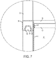
- FIG. 6 is a cross-sectional view of the pontoon boat of FIG. 5 taken along the line 6 - 6 in FIG. 5 .
- FIG. 7 is an enlarged view of a portion of the fence of FIG. 6 .
- FIG. 8 is a cross-sectional view of a clip engaged in a rail.
- FIG. 9 is a cross-sectional view of the clip from FIG. 8 partially inserted in the rail from FIG. 8 .
- FIG. 10 is a perspective view of a clip connected to a cover engaged in a rail.
- FIG. 11 is a perspective view of an alternative embodiment of a clip.
- FIG. 12 is a perspective view of an alternative embodiment of a clip.
- FIG. 13 is a perspective view of the clip of FIG. 12 engaged in a rail.
- FIG. 14 is a cross-sectional view of an alternative embodiment of a clip engaged in a rail.
- FIG. 15 is a cross-sectional view of an alternative embodiment of a clip connected to a cover.
- FIG. 16 is an end elevation view of an alternative embodiment of a rail.
- FIG. 17 is an end elevation view of an alternative embodiment of a rail.
- FIG. 18 is a perspective view of an alternative embodiment of a clip.
- FIG. 19 is a perspective view of an alternative embodiment of a clip.
- FIG. 20 is a perspective view of an alternative embodiment of a clip.
- FIG. 21 is a perspective view of an alternative embodiment of a clip.
- FIG. 22 is a perspective view of an alternative embodiment of a clip.
- FIG. 23 is a perspective view of an alternative embodiment of a clip.
- FIG. 24 is a perspective view of an alternative embodiment of a clip.
- FIG. 25 is a perspective view of an alternative embodiment of a clip.
- FIG. 26 is a perspective view of a portion of an alternative embodiment of a rail.
- FIG. 27 is a perspective view of a portion of an alternative embodiment of a rail.
- a gunnel rail 10 can be attached to each side of a hull 12 for a boat 14 , as seen in FIG. 1 .
- Such a gunnel rail 10 could be used to attach a cover to the boat 14 or accessories such as beverage or tool holders.
- An enlarged portion of the gunnel rail 10 can be more clearly seen in FIG. 2 .
- the gunnel rail 10 illustrated in FIG. 3 includes a hull recess 16 and hull guide 18 for securing the gunnel rail to the boat frame, an interior channel 20 for attaching accessories for use inside the boat 14 and an exterior channel 22 typically used for attaching accessories to the exterior of the boat.
- the exterior channel 22 includes constrictions 24 to help the exterior channel retain the attachment portion of an accessory within the exterior channel such as a snap for a cover.
- the gunnel rail 10 is attached to the boat 14 by inserting one side of the hull 12 into the hull recess 16 of the gunnel rail.
- the hull recess 16 and the hull guide 18 of the gunnel rail 10 help secure the gunnel rail to the boat 14 and properly orient the gunnel rail with respect to the hull 12 .
- the hull 12 can be secured to the gunnel rail 10 such as by welding or bolting.
- Other means for securing a hull 12 to a gunnel rail 10 are known in the industry, the use of which would not defeat the spirit of the invention.
- a rail 26 or fence can be attached to a pontoon boat 28 such as by securing the rail to the platform 30 of the pontoon boat as is seen in FIG. 5 .
- a number of vertical posts 32 are connected to the platform 30 of the pontoon boat 28 .
- the vertical posts 32 are connected to each other by horizontal railings.
- the vertical posts 32 are connected by a top rail 34 and a mid rail 36 .
- the mid rail 36 includes a channel 38 and a skirt leg 40 .
- the skirt leg 40 can be used to hold a decorative skirt 41 that enhances the physical appearance of the pontoon boat 28 and helps prevent items inside the pontoon boat from falling into the water.
- the skirt leg 40 can securely hold the skirt 41 by being crimped to the skirt, welded or other such means known in the industry.
- the skirt leg 41 is typically positioned on the exterior side of the mid rail 36 , such that the skirt appears on the exterior side of the rail and hides the structural components of the rail 26 .
- the skirt leg 41 is positioned on the interior side of the mid rail 36 in order to provide access to a channel 38 for attaching accessories to the exterior of the pontoon boat 28 , such as a cover.
- covers are secured to marine vehicles by installing metal snaps into a channel such as the exterior channel 22 . Then corresponding snaps attached to the cover are mated with the snaps in the channel. This process is tedious, time consuming and frustrating for all of the reasons previously described.
- the present invention relates to compressible members such as clips or fasteners that can be securely held by a large variety of channels exiting in current rails and fences of marine vehicles in use today.
- FIG. 8 shows one embodiment of such a clip.
- the clip 42 shown in FIG. 8 includes a flag, tab or leg 44 for attaching the clip to a substrate such as a fabric or plastic, a channel end or bulbous portion 46 for securing the clip within a channel, and two arms 48 , 50 or prongs for removing the clip from the channel.
- the clip 42 can be attached to the substrate by sewing the substrate to the flag 44 of the clip.
- Other means for attaching a substrate are known in the industry, for example, thermal welding, gluing, riveting, etc., the use of which will not defeat the spirit of the invention.
- the clip 42 could similarly be used to attach bow covers, tops and other enclosures and accessories.
- the first end 48 a , 50 a of the first and second arms 48 , 50 are connected at the channel end or engagement section 46 and diverge at the second end or handles 48 b , 50 b of the first and second arms.
- the channel end 46 can be shaped such that it can be easily inserted into the exterior channel 22 .
- the channel end 46 is a wedge shape.
- the wedge shape allows the channel end 46 to be easily inserted into the exterior channel 22 because a first end or side 52 of the channel end 46 is smaller than the exterior channel and the opening to the channel formed by the constrictions or lips 24 .
- the insertion of the channel end 46 requires less precision than perfectly lining up a snap with its mating counterpart and is therefore, easier and less time consuming and burdensome.
- the clip 42 is sized and shaped such that the channel end 46 must compress to fit between the constrictions 24 in the exterior channel 22 of the gunnel rail 10 as most clearly seen in FIG. 9 .
- One way to compress or deform the channel end 46 is by pinching, compressing or contracting the arms 48 , 50 together to reduce the distance there between. Once the channel end 46 has passed through the constrictions 24 , the channel end can decompress inside the exterior channel 22 as seen in FIG. 8 into its first or base position. When compressed, the clip 42 is in its second or pinched position.
- the clip 42 includes grooves 58 behind the channel end.
- the grooves or recesses 58 interlock with the constrictions 24 to securely hold the clip 42 in place and prevent premature dislodging while the remaining clips are installed.
- the recesses 58 can also be used to provide a clicking sound and/or feel to indicate to the installer of the clip 42 that the clip is properly seated.
- the second end or side 56 of the wedge shaped channel end 46 can be generally about the size of the exterior channel 22 or slightly smaller. If the second end 56 of the channel end 46 is smaller than the size of the exterior channel 22 , the clip 42 will exert an outward force on the exterior channel as the clip tries to decompress to its original size, but is restrained from so doing by the size of the exterior channel. This outward force assists the clip 42 in remaining within and from being undesirably withdrawn from the exterior channel 22 .
- the clips 42 can be attached to the perimeter of a cover material at determined intervals to allow a user to insert the clips into the exterior channel 22 around the perimeter of the boat 14 while standing inside or outside the boat. As progress is made around the perimeter, more of the boat 14 becomes covered until ultimately the entire boat is covered.
- the cover for a boat or other vehicle will begin to become taught.
- the flag 44 is connected to one arm 50 of the clip 42 such that as the taught cover pulls on the flag, a portion of the second arm 50 is pulled a greater distance away from a portion of the first arm 48 . This causes the clip 42 to be more securely held within the exterior channel 22 .
- the cover can be even further tightened by tenting the cover with poles or a strap mechanism if desired.
- a user can pinch the arms 48 , 50 , in the embodiment shown in FIGS. 8-9 , thereby disengaging the grooves or concavities 58 from the constrictions 24 of the exterior channel 22 .
- the clip 42 can then be easily pulled out of the exterior channel 22 .
- the first arm 48 can still be moved towards the second arm quite easily to remove the clip 42 from the exterior channel 22 .
- the remaining clips engaged in the exterior channel become easier to remove.
- the main body of the clip can be made from a resilient material, such as via an extruded plastic that allows for a desired amount of flexibility, spring and/or resilience.
- the continuous extrusion can then be trimmed at specified intervals to provide the proper length of the clip.
- the clip or portions thereof may also be injection molded or created utilizing a co-extrusion process to achieve desired material properties at select locations.
- the flexibility, resilience and/or spring of the plastic from which the clip is made allows for a desired amount of compression and pinching to occur and for the clip to return to its original shape when no forces are acting upon it.
- the clip 60 has a first flag 62 and a second flag 64 .
- the first and second flags 62 , 64 are secured to a cover material 65 by stitching 66 , 68 .
- the clip 60 also has an arm 70 .
- the arm 70 is moved towards the second flag 64 , thereby decreasing the distance between them, to compress or deform the channel end 72 .
- the compression of the channel end 72 causes the recesses 74 to disengage from the constrictions 24 and allows the clip 60 to be withdrawn from the exterior channel 22 .
- the taught cover pulls on one or both of the flags 62 , 64 the arm 70 is pulled a greater distance away from the flag to more securely hold the clip 60 within the exterior channel 22 .
- the clip 76 is similar to the clip 60 previously described.
- the clip 76 generally differs from the clip 60 previously described, in that the clip 76 is rounded at the first end 78 of the channel end 80 .
- the round shape of the first end 78 of the channel end 80 promotes ease of insertion because if any part of the first end is between the constrictions 24 , the round shape of the first end will self-center the channel end.
- FIG. 12 shows another embodiment of a clip 82 , which has a first and second flag 84 , 86 , an arm 88 and a channel end 90 .
- the channel end 90 includes a locator 92 .
- the locator 92 is sized and positioned such that it helps ensure that the channel end 90 is properly positioned within the channel by spacing the channel end a distance equal to the size of the locator away from a channel wall 94 . The proper spacing ensures that the recess 96 is engaged with one of the constrictions 98 .
- the clip 100 has a flag 102 which is used to attach the clip to a cover material 65 , such as, for example by stitching 103 , an arm 104 and a round channel end 106 behind which reside recesses 108 .
- the clip 100 is attached to the cover material 65 at the flag 112 and arm 114 , as seen in FIG. 15 . By allowing extra cover material at the arm 114 , a flap 116 is created that can be used to release the clip 110 from the exterior channel 22 .
- the flap 116 When it is desired to remove the clip 110 from the exterior channel 22 , the flap 116 can be pulled towards the flag 112 causing the channel end 118 to compress and the recesses 120 to disengage from the constrictions 24 . Thereafter, the clip 110 can be withdrawn from the exterior channel 22 .
- the clip and rail configuration is amendable to many sizes and shapes.
- the clip can be configured such that it can be pinched into a compressed state and inserted, and when released expands into an available channel of a marine vehicle.
- one cover clip configuration can be used to attach covers to a variety of existing channel shapes or a single existing channel.
- a clip could be configured so as to be optimally engaged with a channel of new design.
- a clip can also be configured for a particular feature. For example, a clip can be made such that it clicks when properly installed, or must be pinched and rolled into the channel.
- a clip can also be incorporated into accessories such as beverage or tool holders or pockets.
- the clips described herein can also be used with channels made from a variety of materials including, but not limited to aluminum and plastic.
- a rail or fence could be mounted to the side rails, Bimini rails, roof poles or deck edge of a pontoon boat or a channel could be added to an existing extrusion such as the rub rail of a fiberglass boat.
- rub rails used today in the fiberglass boat industry are made from aluminum extrusions. Such aluminum extruded rub rails can be modified to add a channel like those described above. As such, the above described clips could then be used with fiberglass boats without having to drill holes in the fiberglass to add an after-market rail or snaps.
- Modifying the rub rail on fiberglass boats would also eliminate the time and expense of having to drill holes for the metal snaps and the possibility of cracking the fiberglass during such drilling.
- the removal of metal snaps enhances the appearance of the boat so that the smooth fiberglass surface is not interrupted by metal boat snaps.
- the ability to move the above described cover clips along the rub rail around the boat allows boat owners to be able to use a wider variety of covers and cover manufacturers to make covers that fit a wider variety of boats, including fiberglass boats. Covers also stretch a bit over time. If the snaps for a fiberglass boat are permanently located at holes drilled in the fiberglass, the snaps cannot be moved to account for the change in cover size. The inability to move the snaps can lead to an ill-fitting cover that is unsightly and/or does not cover the boat. Since the clips have no specific location in which they must attach to a channel, the clips can be inserted into the channel at any desired location.
Abstract
Description
Claims (21)
Priority Applications (1)
| Application Number | Priority Date | Filing Date | Title |
|---|---|---|---|
| US17/005,826 US11351909B2 (en) | 2014-01-29 | 2020-08-28 | Resilient cover clip |
Applications Claiming Priority (4)
| Application Number | Priority Date | Filing Date | Title |
|---|---|---|---|
| US201461933184P | 2014-01-29 | 2014-01-29 | |
| US14/606,735 US10300833B2 (en) | 2014-01-29 | 2015-01-27 | Resilient cover clip |
| US16/373,179 US10793049B2 (en) | 2014-01-29 | 2019-04-02 | Resilient cover clip |
| US17/005,826 US11351909B2 (en) | 2014-01-29 | 2020-08-28 | Resilient cover clip |
Related Parent Applications (1)
| Application Number | Title | Priority Date | Filing Date |
|---|---|---|---|
| US16/373,179 Continuation US10793049B2 (en) | 2014-01-29 | 2019-04-02 | Resilient cover clip |
Publications (2)
| Publication Number | Publication Date |
|---|---|
| US20200391651A1 US20200391651A1 (en) | 2020-12-17 |
| US11351909B2 true US11351909B2 (en) | 2022-06-07 |
Family
ID=53678620
Family Applications (3)
| Application Number | Title | Priority Date | Filing Date |
|---|---|---|---|
| US14/606,735 Active 2035-08-19 US10300833B2 (en) | 2014-01-29 | 2015-01-27 | Resilient cover clip |
| US16/373,179 Active US10793049B2 (en) | 2014-01-29 | 2019-04-02 | Resilient cover clip |
| US17/005,826 Active 2035-01-31 US11351909B2 (en) | 2014-01-29 | 2020-08-28 | Resilient cover clip |
Family Applications Before (2)
| Application Number | Title | Priority Date | Filing Date |
|---|---|---|---|
| US14/606,735 Active 2035-08-19 US10300833B2 (en) | 2014-01-29 | 2015-01-27 | Resilient cover clip |
| US16/373,179 Active US10793049B2 (en) | 2014-01-29 | 2019-04-02 | Resilient cover clip |
Country Status (2)
| Country | Link |
|---|---|
| US (3) | US10300833B2 (en) |
| CA (1) | CA2880403C (en) |
Families Citing this family (10)
| Publication number | Priority date | Publication date | Assignee | Title |
|---|---|---|---|---|
| USD773691S1 (en) * | 2014-09-29 | 2016-12-06 | Dowco, Inc. | Keder |
| DE102016204483B4 (en) * | 2016-03-17 | 2021-06-17 | Volkswagen Aktiengesellschaft | Fastening element with at least one clip for establishing a connection with a corresponding plug-on element and arrangement of a fastening element on a plug-on element |
| US10865819B2 (en) * | 2016-05-20 | 2020-12-15 | Yazaki North America, Inc. | Tuneless cantilever system |
| US10661882B2 (en) * | 2016-09-01 | 2020-05-26 | Horizon Hobby, LLC | Wing lock and disconnect mechanisms for a RC aircraft |
| EP3589846B1 (en) * | 2017-02-28 | 2022-06-15 | 3M Innovative Properties Company | Attachment device and related methods |
| US10724679B2 (en) * | 2017-07-31 | 2020-07-28 | Taylor Made Group, Llc | Pontoon canvas clip |
| US10619659B2 (en) * | 2017-08-03 | 2020-04-14 | U.S. Farathane Corporation | Closure assembly with collapsible crush barbs configured within a recess cavity defining edge of a first piece for engagement by a projection of a second piece when press fit within the recess cavity in order to engage the pieces together |
| USD902318S1 (en) * | 2018-05-21 | 2020-11-17 | Brunswick Corporation | Safety rail for a marine vessel |
| US10648613B1 (en) | 2018-11-19 | 2020-05-12 | Brunswick Corporation | Methods and devices for securing devices and accessories to a track system |
| US11052972B1 (en) | 2019-10-09 | 2021-07-06 | Brunswick Corporation | Apparatuses for attaching a cover to a marine vessel |
Citations (133)
| Publication number | Priority date | Publication date | Assignee | Title |
|---|---|---|---|---|
| US559506A (en) | 1896-05-05 | Bolting or clamping device | ||
| GB270307A (en) | 1926-04-27 | 1928-08-27 | Ig Farbenindustrie Ag | Improvements in dyeing textile goods |
| US2570533A (en) | 1949-06-06 | 1951-10-09 | Charles F Elliott | Universal automobile cover |
| US2571362A (en) | 1946-09-28 | 1951-10-16 | Hervey Eugene | Foldable canopy frame |
| US2646097A (en) | 1950-12-22 | 1953-07-21 | Delbert R Gaverth | Automobile cover |
| US2732877A (en) | 1956-01-31 | taylor | ||
| US2821989A (en) | 1956-09-10 | 1958-02-04 | Shepard Harwood | Convertible top for boats |
| US2961725A (en) | 1959-04-16 | 1960-11-29 | Mcgee Richard | Fastening device |
| US3059659A (en) | 1961-07-14 | 1962-10-23 | Charles R Ipsen | Boat cover support |
| US3122394A (en) | 1960-06-13 | 1964-02-25 | Brydon Vera May | Convertible top interlock |
| US3172419A (en) | 1963-01-31 | 1965-03-09 | Lone Star Boat Company | Canopy lock for boats |
| US3186129A (en) | 1961-11-15 | 1965-06-01 | Isora Illuminating Ceilings Lt | Ceilings or walls |
| US3354892A (en) | 1965-07-15 | 1967-11-28 | Gentex Corp | Boat canopy |
| US3399687A (en) | 1966-04-27 | 1968-09-03 | Gentex Corp | Simplified boat canopy |
| US3426400A (en) | 1966-12-29 | 1969-02-11 | Anthony Lauro | Plastic hook and eye fastener apparatus |
| US3489452A (en) | 1967-09-08 | 1970-01-13 | Victor Plante | Trailer camper |
| US3572353A (en) | 1969-04-01 | 1971-03-23 | Howard H Pinkley | Convertible tops for boats |
| US3574367A (en) | 1968-01-26 | 1971-04-13 | Johannes Jankowski | Coupling |
| US3654648A (en) | 1970-08-05 | 1972-04-11 | Glastron Boat Co | Windshield |
| US3698409A (en) | 1969-11-12 | 1972-10-17 | Raymond A Koontz | Protective cover structure |
| US3810267A (en) | 1973-09-26 | 1974-05-14 | Bonnet W Inc | Boat windshield mounting means |
| US4075723A (en) | 1976-09-20 | 1978-02-28 | Kellwood Company | Boat cover means |
| US4132335A (en) | 1977-09-27 | 1979-01-02 | Four Star Corporation | Slidable bracket for article carrier |
| US4194636A (en) | 1978-04-14 | 1980-03-25 | Minnesota Mining And Manufacturing Company | Bracket assembly |
| US4209098A (en) | 1978-05-26 | 1980-06-24 | Adams John R | Adjustable storage system for fishing rods |
| US4273278A (en) | 1979-05-07 | 1981-06-16 | Oliver Industries, Inc. | Adjustable luggage rack |
| US4406386A (en) | 1981-04-06 | 1983-09-27 | Masco Corporation | Article carrier and a bracket therefor |
| US4596105A (en) | 1984-12-14 | 1986-06-24 | Aluma-Form, Inc. | Crossarm brace for utility pole |
| US4639033A (en) | 1984-09-14 | 1987-01-27 | Wheatley Donald G | Tonneau cover |
| GB2198396A (en) | 1986-12-01 | 1988-06-15 | York Trailer Co Ltd | Trailer roof joint |
| US4754905A (en) | 1985-09-20 | 1988-07-05 | Bott John Anthony | Vehicle article carrier |
| US4771897A (en) | 1987-10-02 | 1988-09-20 | Jackson Ho | Key hanging device |
| US4863082A (en) | 1988-04-11 | 1989-09-05 | Evans Andrew L | Water ski rack |
| US4869378A (en) | 1988-08-29 | 1989-09-26 | Hospital Systems, Inc. | Mounting rail for hospital appliances and bracket |
| US4993351A (en) | 1989-09-19 | 1991-02-19 | Aldon Industries, Inc. | Rounded top header extrusion for boat windshields |
| US5014458A (en) | 1990-05-15 | 1991-05-14 | Wagner Larry C | Fishing pole holder |
| US5058652A (en) | 1984-09-14 | 1991-10-22 | Wheatley Donald G | Tonneau cover |
| US5152574A (en) | 1991-02-19 | 1992-10-06 | Design Automotive Trim And Accessories, Inc. | Apparatus for attaching a cover for an open-topped vehicle enclosure |
| US5189980A (en) | 1989-09-19 | 1993-03-02 | Aldon Industries Inc. | Rounded top header extrusion for boat windshields |
| US5201487A (en) | 1992-04-17 | 1993-04-13 | Epplett Richard E | Vehicular rooftop rail mount-to-gutter mount adaptor system |
| US5215032A (en) | 1991-11-19 | 1993-06-01 | Ray Industries, Inc. | System, apparatus and method for rapidly attaching a boat cover or canopy to a windshield |
| US5303667A (en) | 1991-07-22 | 1994-04-19 | Aldon Industries, Inc. | Boat camper system and method |
| US5322296A (en) | 1993-08-02 | 1994-06-21 | Weimerskirch Ronald W | Top gun dog fight game |
| US5367977A (en) * | 1991-11-19 | 1994-11-29 | Ray Industries, Inc. | System, apparatus and method for rapidly attaching a boat cover or canopy to a windshield and frame |
| US5438789A (en) | 1994-10-03 | 1995-08-08 | Big Jon, Inc. | Fishing rod holder assembly |
| US5479872A (en) | 1994-02-18 | 1996-01-02 | Hulett; Randall V. | Support for boatcover |
| US5522409A (en) | 1994-11-07 | 1996-06-04 | May; Margaret E. | Collapsible vehicle cover |
| US5577856A (en) | 1993-08-10 | 1996-11-26 | Tezuka; Junichi | Beam support system for forming precompressed wood joints |
| US5617909A (en) | 1992-09-14 | 1997-04-08 | Duginske; Mark A. | Woodworking machinery jig and fixture system |
| US5664793A (en) | 1996-02-21 | 1997-09-09 | Engibarov; Eddy | Quick-change chuck jaws |
| JP2556629Y2 (en) | 1991-07-24 | 1997-12-08 | 澤藤電機株式会社 | Welder fan control |
| US5697320A (en) | 1996-03-19 | 1997-12-16 | Murray; Robert W. | Convertible top/umbrella |
| US5706752A (en) | 1995-08-30 | 1998-01-13 | Premier Marine, Inc. | Bimini sun top frame for a pontoon boat |
| US5706753A (en) | 1996-05-21 | 1998-01-13 | Premier Marine, Inc. | Boat cover fastening system |
| FR2753166A1 (en) | 1996-09-09 | 1998-03-13 | Equipment Nv | Cover for marine vessel |
| US5743208A (en) | 1996-09-24 | 1998-04-28 | Bayliner Marine Corporation | Tensioning device for boat cover |
| US5743204A (en) | 1996-08-29 | 1998-04-28 | Arctic Cat Inc. | Edge trim for watercraft |
| US5768966A (en) | 1992-09-14 | 1998-06-23 | Duginske; Mark A. | Woodworking machinery jig and fixture system |
| US5803104A (en) | 1996-12-28 | 1998-09-08 | Pollen; Randall Paul | Bimini cover for a deck of a water craft |
| US5839388A (en) | 1997-06-24 | 1998-11-24 | N.A. Taylor Company, Inc. | Clip assembly |
| US5901657A (en) | 1997-07-08 | 1999-05-11 | Schwartz; Thomas L. | Support structure for protective cover for boats |
| US5941594A (en) | 1996-08-19 | 1999-08-24 | O'neill; Rory Francis | Protective cover for vehicles |
| US5970904A (en) | 1996-05-21 | 1999-10-26 | Premier Marine, Inc. | Boat cover fastening system |
| US6006692A (en) | 1998-01-28 | 1999-12-28 | Szukhent, Jr.; Steve | Boat canopy mounting apparatus |
| US6053558A (en) | 1997-10-01 | 2000-04-25 | Penda Corporation | Cover assembly for the cargo area of a vehicle |
| US6079051A (en) | 1998-10-13 | 2000-06-27 | O. S. Systems, Incorporated | Waist closure system for waterproof pull-over jacket |
| US6089781A (en) | 1998-08-12 | 2000-07-18 | Hughes Electronics Corporation | Structure utilizing a shape-memory alloy fastener |
| US6129034A (en) | 1998-09-18 | 2000-10-10 | Santa Cruz; Cathy D. | Accessory cover for a boat |
| US6152312A (en) | 1996-05-21 | 2000-11-28 | Ezio Terragni | Suspending system for various types of hanging supports, in particular designed to fit wardrobes |
| US6209477B1 (en) | 1999-08-06 | 2001-04-03 | Harris Kayot, Inc. | Power retractable top for a boat |
| US6227505B1 (en) | 1998-04-10 | 2001-05-08 | Prince Corporation | Adjustable accessory mount |
| US6257306B1 (en) | 1999-06-29 | 2001-07-10 | Penda Corporation | Snap/snapless cover for the cargo area of a vehicle |
| US20020069812A1 (en) * | 2000-12-07 | 2002-06-13 | Harris Kayot, Inc. | Cover fastening system |
| US20020106240A1 (en) | 2001-02-05 | 2002-08-08 | Johnson Raymond D. | Furniture joint |
| US20020109371A1 (en) * | 2001-02-12 | 2002-08-15 | Wheatley Donald G. | Pivoting rail having tonneau cover system |
| US6481679B1 (en) | 2000-11-17 | 2002-11-19 | Bryant K. Bennett | System for mounting medical accessories on supportive structures |
| US20020180235A1 (en) * | 2001-06-01 | 2002-12-05 | Wheatley Donald G. | Hinged j-strip for a tonneau cover |
| US6561117B1 (en) | 2001-12-24 | 2003-05-13 | Curtis Kell | Accessory mounting track for watercraft |
| US6591541B1 (en) | 2001-11-19 | 2003-07-15 | Berton L. Cummings | Fishing tackle holder |
| US6637364B1 (en) | 2002-01-22 | 2003-10-28 | James J. Campeau | Flexible cover support frame tensioning apparatus |
| US6666163B2 (en) | 2002-01-10 | 2003-12-23 | David Pastor | Adjustable boat top |
| US6672241B2 (en) | 2002-07-12 | 2004-01-06 | Bennington Marine, Inc. | Foldable frame for a boat cover |
| US6688668B2 (en) | 2001-10-29 | 2004-02-10 | Bestop, Inc. | Retainer system for vehicle soft tops and tonneau covers |
| US6698603B2 (en) | 2002-04-15 | 2004-03-02 | Stephen Lawson | Extendable rack |
| US6789495B2 (en) | 2002-06-25 | 2004-09-14 | Nelson A. Taylor Co., Inc. | Self-supporting boat cover |
| US6837661B2 (en) | 2002-02-21 | 2005-01-04 | Schwarz Verbindungs-Systeme Gmbh | Detachable insert connection arrangement for a retaining channel and method of connecting |
| US6871749B2 (en) | 2003-04-11 | 2005-03-29 | Dillingham Products Company, Llc | Extendable/retractable valet rack |
| US6886489B2 (en) | 2003-02-04 | 2005-05-03 | Lund Boat Company | Cover fastening system for a boat |
| US6895887B2 (en) | 2003-05-30 | 2005-05-24 | Crestliner, Inc. | Gunwale member for a boat |
| US6983716B1 (en) | 2005-01-25 | 2006-01-10 | Terence Dean Ankney | Automatic bimini top |
| US7063035B2 (en) | 2004-05-11 | 2006-06-20 | Belcher Larry J | Boat mounted blind |
| US7107926B2 (en) | 2004-10-29 | 2006-09-19 | Bennington Marine, Llc | Bimini top main bow connector |
| JP2007009589A (en) | 2005-07-01 | 2007-01-18 | Formosa Saint Jose Corp | Ratchet pulley for tensioning rope |
| US7204466B2 (en) | 2005-03-11 | 2007-04-17 | Wu-Hong Hsieh | Quick-acting telescopic tube |
| US7255511B2 (en) | 2005-02-22 | 2007-08-14 | Dolan Kevin P | Releasable dovetail corner joint |
| US7341231B2 (en) | 2003-09-29 | 2008-03-11 | Lund Boat Company | Accessory mounting system for a boat |
| US20080066794A1 (en) | 2006-09-20 | 2008-03-20 | Zachary Durfee | Automatic hunting blind |
| US20080104808A1 (en) * | 2006-11-03 | 2008-05-08 | James Badalamenti | Tonneau cover fastening system |
| US7380383B2 (en) | 1998-02-04 | 2008-06-03 | Pergo (Europe) Ab | Guiding means at a joint |
| US7401995B2 (en) | 2005-03-31 | 2008-07-22 | Nissan Technical Center North America, Inc. | Channel connector |
| US7418919B2 (en) | 2006-10-26 | 2008-09-02 | Smith Charles M | Fishing boat bathroom privacy system |
| US7430981B2 (en) | 2007-01-22 | 2008-10-07 | Kcs International | Walk-through windshield |
| US7444922B2 (en) | 2003-01-28 | 2008-11-04 | Koganei Corporation | Fastening assembly, fastener, and fluid pressure cylinder unit |
| US7448523B2 (en) | 2002-10-24 | 2008-11-11 | Jac Products, Inc. | Vehicle article carrier having stowable cross bars |
| US7458333B2 (en) | 2006-06-23 | 2008-12-02 | Formosa Saint Jose Corp. | Covering and securing structure for a covering body |
| US7517117B2 (en) | 2003-08-25 | 2009-04-14 | Kmor Innovations, Inc. | Cam lock for track systems |
| US7536971B1 (en) | 2008-02-20 | 2009-05-26 | John Fry | Lowerable water sport tow attachment |
| US7547170B2 (en) | 2003-01-03 | 2009-06-16 | Nissan Technical Center North America, Inc. | Track slot fastener |
| US20090194016A1 (en) | 2007-11-27 | 2009-08-06 | Murphy Mark J | Boat trim strip and cover attachment system |
| US7571691B2 (en) | 2006-07-15 | 2009-08-11 | Russikoff Ronald K | Retractable bimini top device |
| US7634875B2 (en) | 2005-01-10 | 2009-12-22 | Conergy Ag | Mounting system with threaded sliding block |
| US7669723B2 (en) | 2007-10-03 | 2010-03-02 | Jui-Chien Kao | Tool suspension device |
| US7690856B2 (en) | 2003-02-28 | 2010-04-06 | Praktisk Teknologi As | Connection device |
| US7717278B2 (en) | 2008-07-07 | 2010-05-18 | Jui-Chien Kao | Tool suspension device |
| US20100290831A1 (en) | 2008-05-08 | 2010-11-18 | Sauder Woodworking Company | Coupling assembly for furniture components |
| US20100290931A1 (en) | 2008-09-22 | 2010-11-18 | Anthony Jonathan Sanders | Hand-actuated pump |
| US7895964B2 (en) | 2006-07-15 | 2011-03-01 | Russikoff Ronald K | Retractable boat top with arched canopy |
| US7921797B2 (en) | 2008-03-14 | 2011-04-12 | Dowco, Inc. | Bimini top |
| US7950342B2 (en) | 2008-10-03 | 2011-05-31 | Russikoff Ronald K | Automated bimini top device |
| US8070378B2 (en) | 2008-12-19 | 2011-12-06 | Nicholas A. Gargaro, III | Channeled track connector |
| US8418708B2 (en) | 2010-03-31 | 2013-04-16 | TS2 Tactical Spec-Solutions Inc. | Canopy apparatus for a vehicle-mounted weapon system |
| US8601971B2 (en) | 2008-04-18 | 2013-12-10 | Marine Concepts, Llc | Suspended boat cover and suspended boat cover system |
| US8616511B2 (en) | 2008-01-30 | 2013-12-31 | Dowco, Inc. | Apparatus and method for mounting a bimini top |
| US8752498B1 (en) | 2012-08-06 | 2014-06-17 | Michael A. Schwindaman | Automatic bimini top |
| US8800469B2 (en) | 2012-07-27 | 2014-08-12 | Yamaha Motor Corporation, Usa | Boat cover |
| US8857366B2 (en) | 2010-05-28 | 2014-10-14 | Ronald K. Russikoff | Manually-operated boat canopy system |
| US8875646B2 (en) | 2011-09-13 | 2014-11-04 | Taylor Made Group, Llc | Mooring/shipping cover |
| US8876646B2 (en) | 2007-04-23 | 2014-11-04 | Julius Blum Gmbh | Drive for a movable furniture part |
| US8925100B2 (en) | 2009-05-05 | 2014-12-30 | Absolute Software Corporation | Discriminating data protection system |
| US8950416B1 (en) | 2013-04-09 | 2015-02-10 | Michael J. Spellman | Removable and collapsible cover system |
| US9409629B2 (en) | 2013-12-18 | 2016-08-09 | Cabela's Incorporated | Boat cover with an interior strap structure |
| US9718517B2 (en) | 2013-08-19 | 2017-08-01 | Taylor Made Group, Llc | Ratchet playpen cover for a pontoon boat |
| US11052972B1 (en) * | 2019-10-09 | 2021-07-06 | Brunswick Corporation | Apparatuses for attaching a cover to a marine vessel |
Family Cites Families (2)
| Publication number | Priority date | Publication date | Assignee | Title |
|---|---|---|---|---|
| JP2556629B2 (en) * | 1990-12-16 | 1996-11-20 | 三星電管株式會社 | Inner shield and frame connection clip |
| TW332188B (en) | 1996-11-06 | 1998-05-21 | Riso Kagaku Corp | The ink-supplying apparatus for printer |
-
2015
- 2015-01-27 US US14/606,735 patent/US10300833B2/en active Active
- 2015-01-29 CA CA2880403A patent/CA2880403C/en active Active
-
2019
- 2019-04-02 US US16/373,179 patent/US10793049B2/en active Active
-
2020
- 2020-08-28 US US17/005,826 patent/US11351909B2/en active Active
Patent Citations (133)
| Publication number | Priority date | Publication date | Assignee | Title |
|---|---|---|---|---|
| US2732877A (en) | 1956-01-31 | taylor | ||
| US559506A (en) | 1896-05-05 | Bolting or clamping device | ||
| GB270307A (en) | 1926-04-27 | 1928-08-27 | Ig Farbenindustrie Ag | Improvements in dyeing textile goods |
| US2571362A (en) | 1946-09-28 | 1951-10-16 | Hervey Eugene | Foldable canopy frame |
| US2570533A (en) | 1949-06-06 | 1951-10-09 | Charles F Elliott | Universal automobile cover |
| US2646097A (en) | 1950-12-22 | 1953-07-21 | Delbert R Gaverth | Automobile cover |
| US2821989A (en) | 1956-09-10 | 1958-02-04 | Shepard Harwood | Convertible top for boats |
| US2961725A (en) | 1959-04-16 | 1960-11-29 | Mcgee Richard | Fastening device |
| US3122394A (en) | 1960-06-13 | 1964-02-25 | Brydon Vera May | Convertible top interlock |
| US3059659A (en) | 1961-07-14 | 1962-10-23 | Charles R Ipsen | Boat cover support |
| US3186129A (en) | 1961-11-15 | 1965-06-01 | Isora Illuminating Ceilings Lt | Ceilings or walls |
| US3172419A (en) | 1963-01-31 | 1965-03-09 | Lone Star Boat Company | Canopy lock for boats |
| US3354892A (en) | 1965-07-15 | 1967-11-28 | Gentex Corp | Boat canopy |
| US3399687A (en) | 1966-04-27 | 1968-09-03 | Gentex Corp | Simplified boat canopy |
| US3426400A (en) | 1966-12-29 | 1969-02-11 | Anthony Lauro | Plastic hook and eye fastener apparatus |
| US3489452A (en) | 1967-09-08 | 1970-01-13 | Victor Plante | Trailer camper |
| US3574367A (en) | 1968-01-26 | 1971-04-13 | Johannes Jankowski | Coupling |
| US3572353A (en) | 1969-04-01 | 1971-03-23 | Howard H Pinkley | Convertible tops for boats |
| US3698409A (en) | 1969-11-12 | 1972-10-17 | Raymond A Koontz | Protective cover structure |
| US3654648A (en) | 1970-08-05 | 1972-04-11 | Glastron Boat Co | Windshield |
| US3810267A (en) | 1973-09-26 | 1974-05-14 | Bonnet W Inc | Boat windshield mounting means |
| US4075723A (en) | 1976-09-20 | 1978-02-28 | Kellwood Company | Boat cover means |
| US4132335A (en) | 1977-09-27 | 1979-01-02 | Four Star Corporation | Slidable bracket for article carrier |
| US4194636A (en) | 1978-04-14 | 1980-03-25 | Minnesota Mining And Manufacturing Company | Bracket assembly |
| US4209098A (en) | 1978-05-26 | 1980-06-24 | Adams John R | Adjustable storage system for fishing rods |
| US4273278A (en) | 1979-05-07 | 1981-06-16 | Oliver Industries, Inc. | Adjustable luggage rack |
| US4406386A (en) | 1981-04-06 | 1983-09-27 | Masco Corporation | Article carrier and a bracket therefor |
| US4639033A (en) | 1984-09-14 | 1987-01-27 | Wheatley Donald G | Tonneau cover |
| US5058652A (en) | 1984-09-14 | 1991-10-22 | Wheatley Donald G | Tonneau cover |
| US4596105A (en) | 1984-12-14 | 1986-06-24 | Aluma-Form, Inc. | Crossarm brace for utility pole |
| US4754905A (en) | 1985-09-20 | 1988-07-05 | Bott John Anthony | Vehicle article carrier |
| GB2198396A (en) | 1986-12-01 | 1988-06-15 | York Trailer Co Ltd | Trailer roof joint |
| US4771897A (en) | 1987-10-02 | 1988-09-20 | Jackson Ho | Key hanging device |
| US4863082A (en) | 1988-04-11 | 1989-09-05 | Evans Andrew L | Water ski rack |
| US4869378A (en) | 1988-08-29 | 1989-09-26 | Hospital Systems, Inc. | Mounting rail for hospital appliances and bracket |
| US4993351A (en) | 1989-09-19 | 1991-02-19 | Aldon Industries, Inc. | Rounded top header extrusion for boat windshields |
| US5189980A (en) | 1989-09-19 | 1993-03-02 | Aldon Industries Inc. | Rounded top header extrusion for boat windshields |
| US5014458A (en) | 1990-05-15 | 1991-05-14 | Wagner Larry C | Fishing pole holder |
| US5152574A (en) | 1991-02-19 | 1992-10-06 | Design Automotive Trim And Accessories, Inc. | Apparatus for attaching a cover for an open-topped vehicle enclosure |
| US5303667A (en) | 1991-07-22 | 1994-04-19 | Aldon Industries, Inc. | Boat camper system and method |
| JP2556629Y2 (en) | 1991-07-24 | 1997-12-08 | 澤藤電機株式会社 | Welder fan control |
| US5215032A (en) | 1991-11-19 | 1993-06-01 | Ray Industries, Inc. | System, apparatus and method for rapidly attaching a boat cover or canopy to a windshield |
| US5367977A (en) * | 1991-11-19 | 1994-11-29 | Ray Industries, Inc. | System, apparatus and method for rapidly attaching a boat cover or canopy to a windshield and frame |
| US5201487A (en) | 1992-04-17 | 1993-04-13 | Epplett Richard E | Vehicular rooftop rail mount-to-gutter mount adaptor system |
| US5617909A (en) | 1992-09-14 | 1997-04-08 | Duginske; Mark A. | Woodworking machinery jig and fixture system |
| US5768966A (en) | 1992-09-14 | 1998-06-23 | Duginske; Mark A. | Woodworking machinery jig and fixture system |
| US5322296A (en) | 1993-08-02 | 1994-06-21 | Weimerskirch Ronald W | Top gun dog fight game |
| US5577856A (en) | 1993-08-10 | 1996-11-26 | Tezuka; Junichi | Beam support system for forming precompressed wood joints |
| US5479872A (en) | 1994-02-18 | 1996-01-02 | Hulett; Randall V. | Support for boatcover |
| US5438789A (en) | 1994-10-03 | 1995-08-08 | Big Jon, Inc. | Fishing rod holder assembly |
| US5522409A (en) | 1994-11-07 | 1996-06-04 | May; Margaret E. | Collapsible vehicle cover |
| US5706752A (en) | 1995-08-30 | 1998-01-13 | Premier Marine, Inc. | Bimini sun top frame for a pontoon boat |
| US5664793A (en) | 1996-02-21 | 1997-09-09 | Engibarov; Eddy | Quick-change chuck jaws |
| US5697320A (en) | 1996-03-19 | 1997-12-16 | Murray; Robert W. | Convertible top/umbrella |
| US6152312A (en) | 1996-05-21 | 2000-11-28 | Ezio Terragni | Suspending system for various types of hanging supports, in particular designed to fit wardrobes |
| US5706753A (en) | 1996-05-21 | 1998-01-13 | Premier Marine, Inc. | Boat cover fastening system |
| US5970904A (en) | 1996-05-21 | 1999-10-26 | Premier Marine, Inc. | Boat cover fastening system |
| US5941594A (en) | 1996-08-19 | 1999-08-24 | O'neill; Rory Francis | Protective cover for vehicles |
| US5743204A (en) | 1996-08-29 | 1998-04-28 | Arctic Cat Inc. | Edge trim for watercraft |
| FR2753166A1 (en) | 1996-09-09 | 1998-03-13 | Equipment Nv | Cover for marine vessel |
| US5743208A (en) | 1996-09-24 | 1998-04-28 | Bayliner Marine Corporation | Tensioning device for boat cover |
| US5803104A (en) | 1996-12-28 | 1998-09-08 | Pollen; Randall Paul | Bimini cover for a deck of a water craft |
| US5839388A (en) | 1997-06-24 | 1998-11-24 | N.A. Taylor Company, Inc. | Clip assembly |
| US5901657A (en) | 1997-07-08 | 1999-05-11 | Schwartz; Thomas L. | Support structure for protective cover for boats |
| US6053558A (en) | 1997-10-01 | 2000-04-25 | Penda Corporation | Cover assembly for the cargo area of a vehicle |
| US6006692A (en) | 1998-01-28 | 1999-12-28 | Szukhent, Jr.; Steve | Boat canopy mounting apparatus |
| US7380383B2 (en) | 1998-02-04 | 2008-06-03 | Pergo (Europe) Ab | Guiding means at a joint |
| US6227505B1 (en) | 1998-04-10 | 2001-05-08 | Prince Corporation | Adjustable accessory mount |
| US6089781A (en) | 1998-08-12 | 2000-07-18 | Hughes Electronics Corporation | Structure utilizing a shape-memory alloy fastener |
| US6129034A (en) | 1998-09-18 | 2000-10-10 | Santa Cruz; Cathy D. | Accessory cover for a boat |
| US6079051A (en) | 1998-10-13 | 2000-06-27 | O. S. Systems, Incorporated | Waist closure system for waterproof pull-over jacket |
| US6257306B1 (en) | 1999-06-29 | 2001-07-10 | Penda Corporation | Snap/snapless cover for the cargo area of a vehicle |
| US6209477B1 (en) | 1999-08-06 | 2001-04-03 | Harris Kayot, Inc. | Power retractable top for a boat |
| US6481679B1 (en) | 2000-11-17 | 2002-11-19 | Bryant K. Bennett | System for mounting medical accessories on supportive structures |
| US20020069812A1 (en) * | 2000-12-07 | 2002-06-13 | Harris Kayot, Inc. | Cover fastening system |
| US20020106240A1 (en) | 2001-02-05 | 2002-08-08 | Johnson Raymond D. | Furniture joint |
| US20020109371A1 (en) * | 2001-02-12 | 2002-08-15 | Wheatley Donald G. | Pivoting rail having tonneau cover system |
| US20020180235A1 (en) * | 2001-06-01 | 2002-12-05 | Wheatley Donald G. | Hinged j-strip for a tonneau cover |
| US6688668B2 (en) | 2001-10-29 | 2004-02-10 | Bestop, Inc. | Retainer system for vehicle soft tops and tonneau covers |
| US6591541B1 (en) | 2001-11-19 | 2003-07-15 | Berton L. Cummings | Fishing tackle holder |
| US6561117B1 (en) | 2001-12-24 | 2003-05-13 | Curtis Kell | Accessory mounting track for watercraft |
| US6666163B2 (en) | 2002-01-10 | 2003-12-23 | David Pastor | Adjustable boat top |
| US6637364B1 (en) | 2002-01-22 | 2003-10-28 | James J. Campeau | Flexible cover support frame tensioning apparatus |
| US6837661B2 (en) | 2002-02-21 | 2005-01-04 | Schwarz Verbindungs-Systeme Gmbh | Detachable insert connection arrangement for a retaining channel and method of connecting |
| US6698603B2 (en) | 2002-04-15 | 2004-03-02 | Stephen Lawson | Extendable rack |
| US6789495B2 (en) | 2002-06-25 | 2004-09-14 | Nelson A. Taylor Co., Inc. | Self-supporting boat cover |
| US6672241B2 (en) | 2002-07-12 | 2004-01-06 | Bennington Marine, Inc. | Foldable frame for a boat cover |
| US7448523B2 (en) | 2002-10-24 | 2008-11-11 | Jac Products, Inc. | Vehicle article carrier having stowable cross bars |
| US7547170B2 (en) | 2003-01-03 | 2009-06-16 | Nissan Technical Center North America, Inc. | Track slot fastener |
| US7444922B2 (en) | 2003-01-28 | 2008-11-04 | Koganei Corporation | Fastening assembly, fastener, and fluid pressure cylinder unit |
| US6886489B2 (en) | 2003-02-04 | 2005-05-03 | Lund Boat Company | Cover fastening system for a boat |
| US7690856B2 (en) | 2003-02-28 | 2010-04-06 | Praktisk Teknologi As | Connection device |
| US6871749B2 (en) | 2003-04-11 | 2005-03-29 | Dillingham Products Company, Llc | Extendable/retractable valet rack |
| US6895887B2 (en) | 2003-05-30 | 2005-05-24 | Crestliner, Inc. | Gunwale member for a boat |
| US7517117B2 (en) | 2003-08-25 | 2009-04-14 | Kmor Innovations, Inc. | Cam lock for track systems |
| US7341231B2 (en) | 2003-09-29 | 2008-03-11 | Lund Boat Company | Accessory mounting system for a boat |
| US7063035B2 (en) | 2004-05-11 | 2006-06-20 | Belcher Larry J | Boat mounted blind |
| US7107926B2 (en) | 2004-10-29 | 2006-09-19 | Bennington Marine, Llc | Bimini top main bow connector |
| US7634875B2 (en) | 2005-01-10 | 2009-12-22 | Conergy Ag | Mounting system with threaded sliding block |
| US6983716B1 (en) | 2005-01-25 | 2006-01-10 | Terence Dean Ankney | Automatic bimini top |
| US7255511B2 (en) | 2005-02-22 | 2007-08-14 | Dolan Kevin P | Releasable dovetail corner joint |
| US7204466B2 (en) | 2005-03-11 | 2007-04-17 | Wu-Hong Hsieh | Quick-acting telescopic tube |
| US7401995B2 (en) | 2005-03-31 | 2008-07-22 | Nissan Technical Center North America, Inc. | Channel connector |
| JP2007009589A (en) | 2005-07-01 | 2007-01-18 | Formosa Saint Jose Corp | Ratchet pulley for tensioning rope |
| US7458333B2 (en) | 2006-06-23 | 2008-12-02 | Formosa Saint Jose Corp. | Covering and securing structure for a covering body |
| US7895964B2 (en) | 2006-07-15 | 2011-03-01 | Russikoff Ronald K | Retractable boat top with arched canopy |
| US7571691B2 (en) | 2006-07-15 | 2009-08-11 | Russikoff Ronald K | Retractable bimini top device |
| US20080066794A1 (en) | 2006-09-20 | 2008-03-20 | Zachary Durfee | Automatic hunting blind |
| US7418919B2 (en) | 2006-10-26 | 2008-09-02 | Smith Charles M | Fishing boat bathroom privacy system |
| US20080104808A1 (en) * | 2006-11-03 | 2008-05-08 | James Badalamenti | Tonneau cover fastening system |
| US7430981B2 (en) | 2007-01-22 | 2008-10-07 | Kcs International | Walk-through windshield |
| US8876646B2 (en) | 2007-04-23 | 2014-11-04 | Julius Blum Gmbh | Drive for a movable furniture part |
| US7669723B2 (en) | 2007-10-03 | 2010-03-02 | Jui-Chien Kao | Tool suspension device |
| US20090194016A1 (en) | 2007-11-27 | 2009-08-06 | Murphy Mark J | Boat trim strip and cover attachment system |
| US8616511B2 (en) | 2008-01-30 | 2013-12-31 | Dowco, Inc. | Apparatus and method for mounting a bimini top |
| US7536971B1 (en) | 2008-02-20 | 2009-05-26 | John Fry | Lowerable water sport tow attachment |
| US7921797B2 (en) | 2008-03-14 | 2011-04-12 | Dowco, Inc. | Bimini top |
| US8601971B2 (en) | 2008-04-18 | 2013-12-10 | Marine Concepts, Llc | Suspended boat cover and suspended boat cover system |
| US20100290831A1 (en) | 2008-05-08 | 2010-11-18 | Sauder Woodworking Company | Coupling assembly for furniture components |
| US7717278B2 (en) | 2008-07-07 | 2010-05-18 | Jui-Chien Kao | Tool suspension device |
| US20100290931A1 (en) | 2008-09-22 | 2010-11-18 | Anthony Jonathan Sanders | Hand-actuated pump |
| US7950342B2 (en) | 2008-10-03 | 2011-05-31 | Russikoff Ronald K | Automated bimini top device |
| US8070378B2 (en) | 2008-12-19 | 2011-12-06 | Nicholas A. Gargaro, III | Channeled track connector |
| US8925100B2 (en) | 2009-05-05 | 2014-12-30 | Absolute Software Corporation | Discriminating data protection system |
| US8418708B2 (en) | 2010-03-31 | 2013-04-16 | TS2 Tactical Spec-Solutions Inc. | Canopy apparatus for a vehicle-mounted weapon system |
| US8857366B2 (en) | 2010-05-28 | 2014-10-14 | Ronald K. Russikoff | Manually-operated boat canopy system |
| US8875646B2 (en) | 2011-09-13 | 2014-11-04 | Taylor Made Group, Llc | Mooring/shipping cover |
| US8800469B2 (en) | 2012-07-27 | 2014-08-12 | Yamaha Motor Corporation, Usa | Boat cover |
| US8752498B1 (en) | 2012-08-06 | 2014-06-17 | Michael A. Schwindaman | Automatic bimini top |
| US8950416B1 (en) | 2013-04-09 | 2015-02-10 | Michael J. Spellman | Removable and collapsible cover system |
| US9718517B2 (en) | 2013-08-19 | 2017-08-01 | Taylor Made Group, Llc | Ratchet playpen cover for a pontoon boat |
| US9409629B2 (en) | 2013-12-18 | 2016-08-09 | Cabela's Incorporated | Boat cover with an interior strap structure |
| US11052972B1 (en) * | 2019-10-09 | 2021-07-06 | Brunswick Corporation | Apparatuses for attaching a cover to a marine vessel |
Non-Patent Citations (18)
| Title |
|---|
| Brochure and catalog for Harris Flotebote; vol. 4; Issue 1; 2013. |
| Brochure; Dec. 10, 2013; Side-Winder Pontoon Roll Cover. |
| https://www.youtube.com/watch?v=kanacQovuzU; Dec. 10, 2013; Side-Winder Pontoon Roll Cover Demonstration. |
| Photograph of Bennington Clip; 2015; (prior art for purposes of prosecution). |
| Website screenshot https://www.outube.com/watch?v=9BEImomRxV4; Sea to Summit—13 Liter Lightweight Dry Sack by TheGearTester—YouTube; published Dec. 4, 2015. |
| Website screenshot https://www.youtube.com/watch?v=2qhNBqXFrME; How to install a contour fit PWC cover—YouTube; published Nov. 8, 2007. |
| Website screenshot https://wwwyoutube.com/watch?v=wX3pinLR4_s; Explore the eBages TLS Expandable 22 Carry-On—YouTube; captured Nov. 28, 2012. |
| Website Screenshot; http://www.boattest.com/boats/boat_video.aspx?ID=3035; BoatTest.com; captured Feb. 20, 2015; (prior art for purposes of prosecution). |
| Website screenshot; http://www.crestliner-legacy/; Crestliner Legacy; captured Feb. 20, 2015; date clip J-Hood introduced 2005. |
| Website screenshot; http://www.ebay.com/ltm/HARRIS-KAYOT-FSH-230-PONTOON-BOAT-COVER-BURGUNDY-W-VENTS-MARINE-BOAT-/191343936000; ebay listing of Harris Kayot FSH 230 Pontoon Boat Cover Burgundy w/Vents Marine Boat; captured Feb. 20, 2015; date identified on tag Oct. 6, 2010. |
| Website screenshot; https://shop.pontoons.com/store/detail/259/playpen_storage_covers_miscellaneous_canvas/2002/j_clip_kit_b/; Premier Marine, Inc.; captured Feb. 20, 2015; (prior art for purposes of prosecution). |
| Website screenshot; https://web.archive.org/web/20120820000834/http://www.websweeper.com/php/boat_covers/bc-018.php; Aug. 20, 2012. |
| Website screenshot; https://web.archive.org/web/20130925032949/http://www.outdoorfabricscanada.com/Vents-Mooring-Supports_c_304.html; Sep. 25, 2013. |
| Website screenshot; https://web.archive.org/web/20131020233755/http://www.wayfair.com/Navigloo-19-tO-22%C2%BD-ft-Storage-Storage-System-Fishing-Runabout-with-Tarpaulin-Cover-3370-NAVI1004.html; Oct. 20, 2013. |
| Website screenshot; https://web.archive.rg/web/20131108112133/http://www.canvas-boat-cover-and-repair-advisor.com/boat-cover-supports.html; Nov. 8, 2013. |
| Website screenshot; https://www.youtub.com/watch?v=RepAaag_wbQ; link to youtube video titled How to Use Bennington's Quick Clip Mooring Cover; captured Feb. 20, 2015; published Jun. 10, 2013. |
| Website screenshot; https://www.youtube.com/watch?v=1jGOfijiVM; How to Use an Adjustable Support Pole in a Cover; published Dec. 12, 2013. |
| Website screenshot; https://www.youtube.com/watch?v=k9vbnj5KYq0; Ameritex Pontoon Cover Innovation Award Video; admitted prior art for the purposes of prosecution. |
Also Published As
| Publication number | Publication date |
|---|---|
| US10793049B2 (en) | 2020-10-06 |
| CA2880403C (en) | 2023-01-10 |
| US20190225136A1 (en) | 2019-07-25 |
| US20150211556A1 (en) | 2015-07-30 |
| CA2880403A1 (en) | 2015-07-29 |
| US20200391651A1 (en) | 2020-12-17 |
| US10300833B2 (en) | 2019-05-28 |
Similar Documents
| Publication | Publication Date | Title |
|---|---|---|
| US11351909B2 (en) | Resilient cover clip | |
| US9759373B2 (en) | Fabric attachment system | |
| US4688304A (en) | Tarp fastener | |
| US10668955B2 (en) | Fender flare for vehicles | |
| US7484472B1 (en) | Retractable pontoon boat cover | |
| US4903629A (en) | Boat slide channel assembly | |
| US9657894B2 (en) | Mounting clips and adapters for mounting decorative articles | |
| EP0280441A1 (en) | Method and apparatus for releasably fastening a stretchable fabric cover | |
| US9718517B2 (en) | Ratchet playpen cover for a pontoon boat | |
| US20090194016A1 (en) | Boat trim strip and cover attachment system | |
| US9777756B2 (en) | Glass edge snap attachment | |
| US7281486B2 (en) | Marine windshield and cockpit cover attachment system | |
| US9682759B1 (en) | Trolling motor lift cord clamp device | |
| US6457189B1 (en) | Pool liner retainer with cap | |
| US20140026383A1 (en) | Systems and methods for covering ladder rung throughbores | |
| US5622136A (en) | Boat canopy mounting system | |
| US6763776B1 (en) | Cleat device for a flexible line and method of using same | |
| US10724679B2 (en) | Pontoon canvas clip | |
| US7025012B1 (en) | Boat cleat and method of securing a rope thereto | |
| US20080235862A1 (en) | Multi-Purpose Beading For Swimming Pool Liners | |
| US7434534B2 (en) | Fastener for a boat cover | |
| US7503275B2 (en) | System for attaching a flexible enclosure to a boat windshield frame | |
| US5134964A (en) | Flexible security loop for kayaks | |
| US20200144757A1 (en) | Resilient snap connector system | |
| US5088438A (en) | Apparatus for flexible marine windows |
Legal Events
| Date | Code | Title | Description |
|---|---|---|---|
| FEPP | Fee payment procedure |
Free format text: ENTITY STATUS SET TO UNDISCOUNTED (ORIGINAL EVENT CODE: BIG.); ENTITY STATUS OF PATENT OWNER: LARGE ENTITY |
|
| AS | Assignment |
Owner name: DOWCO, INC., WISCONSIN Free format text: ASSIGNMENT OF ASSIGNORS INTEREST;ASSIGNORS:ALEXANDER, JON;HOUGH, JUSTIN;SIGNING DATES FROM 20150203 TO 20150204;REEL/FRAME:053646/0992 |
|
| STPP | Information on status: patent application and granting procedure in general |
Free format text: DOCKETED NEW CASE - READY FOR EXAMINATION |
|
| STPP | Information on status: patent application and granting procedure in general |
Free format text: NON FINAL ACTION MAILED |
|
| STPP | Information on status: patent application and granting procedure in general |
Free format text: RESPONSE TO NON-FINAL OFFICE ACTION ENTERED AND FORWARDED TO EXAMINER |
|
| STPP | Information on status: patent application and granting procedure in general |
Free format text: NOTICE OF ALLOWANCE MAILED -- APPLICATION RECEIVED IN OFFICE OF PUBLICATIONS |
|
| STPP | Information on status: patent application and granting procedure in general |
Free format text: PUBLICATIONS -- ISSUE FEE PAYMENT VERIFIED |
|
| STCF | Information on status: patent grant |
Free format text: PATENTED CASE |