US11348204B2 - Image adaptive noise reduction method and device thereof - Google Patents
Image adaptive noise reduction method and device thereof Download PDFInfo
- Publication number
- US11348204B2 US11348204B2 US16/646,054 US202016646054A US11348204B2 US 11348204 B2 US11348204 B2 US 11348204B2 US 202016646054 A US202016646054 A US 202016646054A US 11348204 B2 US11348204 B2 US 11348204B2
- Authority
- US
- United States
- Prior art keywords
- sub
- image
- significant
- blocks
- noise reduction
- Prior art date
- Legal status (The legal status is an assumption and is not a legal conclusion. Google has not performed a legal analysis and makes no representation as to the accuracy of the status listed.)
- Active, expires
Links
- 230000009467 reduction Effects 0.000 title claims abstract description 72
- 238000000034 method Methods 0.000 title claims abstract description 41
- 230000003044 adaptive effect Effects 0.000 title claims abstract description 38
- 238000006243 chemical reaction Methods 0.000 claims abstract description 48
- 238000001914 filtration Methods 0.000 claims abstract description 27
- 238000004458 analytical method Methods 0.000 claims abstract description 20
- 230000011218 segmentation Effects 0.000 claims abstract description 14
- 230000002146 bilateral effect Effects 0.000 claims description 24
- 238000010606 normalization Methods 0.000 claims description 7
- 238000004364 calculation method Methods 0.000 claims description 6
- 238000012545 processing Methods 0.000 description 9
- 238000010586 diagram Methods 0.000 description 6
- 230000015654 memory Effects 0.000 description 6
- 230000000903 blocking effect Effects 0.000 description 3
- 230000006870 function Effects 0.000 description 3
- 230000009286 beneficial effect Effects 0.000 description 2
- 230000006835 compression Effects 0.000 description 2
- 238000007906 compression Methods 0.000 description 2
- 230000000694 effects Effects 0.000 description 2
- 239000011159 matrix material Substances 0.000 description 2
- 238000012986 modification Methods 0.000 description 2
- 230000004048 modification Effects 0.000 description 2
- 230000008569 process Effects 0.000 description 2
- 241000255925 Diptera Species 0.000 description 1
- 238000004891 communication Methods 0.000 description 1
- 230000006837 decompression Effects 0.000 description 1
- 238000005516 engineering process Methods 0.000 description 1
- 238000003709 image segmentation Methods 0.000 description 1
- 230000003287 optical effect Effects 0.000 description 1
- 238000012805 post-processing Methods 0.000 description 1
Images


Classifications
-
- G—PHYSICS
- G06—COMPUTING; CALCULATING OR COUNTING
- G06T—IMAGE DATA PROCESSING OR GENERATION, IN GENERAL
- G06T5/00—Image enhancement or restoration
- G06T5/001—Image restoration
- G06T5/002—Denoising; Smoothing
-
- G06T5/70—
-
- G—PHYSICS
- G06—COMPUTING; CALCULATING OR COUNTING
- G06T—IMAGE DATA PROCESSING OR GENERATION, IN GENERAL
- G06T7/00—Image analysis
- G06T7/10—Segmentation; Edge detection
- G06T7/11—Region-based segmentation
-
- G—PHYSICS
- G06—COMPUTING; CALCULATING OR COUNTING
- G06T—IMAGE DATA PROCESSING OR GENERATION, IN GENERAL
- G06T5/00—Image enhancement or restoration
- G06T5/10—Image enhancement or restoration by non-spatial domain filtering
-
- G—PHYSICS
- G06—COMPUTING; CALCULATING OR COUNTING
- G06T—IMAGE DATA PROCESSING OR GENERATION, IN GENERAL
- G06T5/00—Image enhancement or restoration
- G06T5/20—Image enhancement or restoration by the use of local operators
-
- G—PHYSICS
- G06—COMPUTING; CALCULATING OR COUNTING
- G06T—IMAGE DATA PROCESSING OR GENERATION, IN GENERAL
- G06T5/00—Image enhancement or restoration
- G06T5/50—Image enhancement or restoration by the use of more than one image, e.g. averaging, subtraction
-
- G—PHYSICS
- G06—COMPUTING; CALCULATING OR COUNTING
- G06T—IMAGE DATA PROCESSING OR GENERATION, IN GENERAL
- G06T7/00—Image analysis
- G06T7/10—Segmentation; Edge detection
- G06T7/136—Segmentation; Edge detection involving thresholding
-
- G—PHYSICS
- G06—COMPUTING; CALCULATING OR COUNTING
- G06T—IMAGE DATA PROCESSING OR GENERATION, IN GENERAL
- G06T2207/00—Indexing scheme for image analysis or image enhancement
- G06T2207/10—Image acquisition modality
- G06T2207/10024—Color image
-
- G—PHYSICS
- G06—COMPUTING; CALCULATING OR COUNTING
- G06T—IMAGE DATA PROCESSING OR GENERATION, IN GENERAL
- G06T2207/00—Indexing scheme for image analysis or image enhancement
- G06T2207/20—Special algorithmic details
- G06T2207/20004—Adaptive image processing
-
- G—PHYSICS
- G06—COMPUTING; CALCULATING OR COUNTING
- G06T—IMAGE DATA PROCESSING OR GENERATION, IN GENERAL
- G06T2207/00—Indexing scheme for image analysis or image enhancement
- G06T2207/20—Special algorithmic details
- G06T2207/20021—Dividing image into blocks, subimages or windows
-
- G—PHYSICS
- G06—COMPUTING; CALCULATING OR COUNTING
- G06T—IMAGE DATA PROCESSING OR GENERATION, IN GENERAL
- G06T2207/00—Indexing scheme for image analysis or image enhancement
- G06T2207/20—Special algorithmic details
- G06T2207/20024—Filtering details
- G06T2207/20028—Bilateral filtering
-
- G—PHYSICS
- G06—COMPUTING; CALCULATING OR COUNTING
- G06T—IMAGE DATA PROCESSING OR GENERATION, IN GENERAL
- G06T2207/00—Indexing scheme for image analysis or image enhancement
- G06T2207/20—Special algorithmic details
- G06T2207/20076—Probabilistic image processing
-
- G—PHYSICS
- G06—COMPUTING; CALCULATING OR COUNTING
- G06T—IMAGE DATA PROCESSING OR GENERATION, IN GENERAL
- G06T2207/00—Indexing scheme for image analysis or image enhancement
- G06T2207/20—Special algorithmic details
- G06T2207/20212—Image combination
- G06T2207/20221—Image fusion; Image merging
Definitions
- the present invention relates to the field of image processing technology, and in particular, to an image adaptive noise reduction method and a device thereof.
- BDCT Discrete Cosine Transform
- Blocking and mosquito noise caused by traditional decompression use global noise reduction methods, such as bilateral filtering noise reduction methods with uniform parameters for an entire image. If the bilateral filtering noise reduction methods with uniform parameters are used for the image, regions with more details will still be blurred, and reducing image qualities. Moreover, due to limited hardware resources, complex algorithms will cause longer processing time and cannot be processed in real time.
- an objective of the present invention is to provide a new technical solution to solve one of the above problems.
- the present invention provides a method based on the human eye significance analysis, which can reduce consumption of hardware resources to a certain extent when the human eye is difficult to detect, and obtains a detailed map through local entropy, which can retain details as much as possible while denoising.
- the present invention provides an image adaptive noise reduction method, comprising following steps of: (1) dividing an original RGB image with noise into a plurality of sub-blocks; (2) performing an image space conversion from an RGB space to a YCbCr space for all the sub-blocks; (3) performing a significance analysis on each of the sub-blocks to obtain a significant characteristic map after the image space conversion; (4) determining whether a weight threshold of the significant characteristic map of a currently processed one of the sub-blocks is greater than a significant standard value, wherein if the weight threshold is greater than the significant standard value, the currently processed one of the sub-blocks is classified into a significant characteristic region, otherwise currently processed one of the sub-blocks is classified into a non-significant characteristic region, wherein significant values of the sub-blocks are generated and recorded, and all the significant characteristic maps are examined to obtain the significant characteristic region and the non-significant characteristic region; (5) obtaining a detailed map through a local entropy calculation for each sub-block in the significant characteristic region;
- the present invention further provides an image adaptive noise reduction method, comprising following steps of: (1) dividing an original RGB image with noise into a plurality of sub-blocks; (2) performing an image space conversion from an RGB space to a YCbCr space for all the sub-blocks; (3) performing a significance analysis on each of the sub-blocks to obtain a significant characteristic map after the image space conversion; (4) performing a threshold segmentation on all the significant characteristic maps by a significant standard value to obtain a significant characteristic region and a non-significant characteristic region; (5) performing adaptive noise reduction on pixel values of the sub-blocks in the significant characteristic region to output first images, and each the sub-block in the non-significant characteristic region outputs a second image with an original pixel value, and mixing all the first images with the second images to obtain a mixed image; and (6) performing an image space inverse conversion from the YCbCr space to the RGB space for the mixed image and outputting a final image.
- the present invention further provides an image adaptive noise reduction device, comprising: an image division module for dividing an original RGB image with noise into a plurality of sub-blocks; an image space conversion module for performing an image space conversion from an RGB space to a YCbCr space on all the sub-blocks; a significance analysis module for performing a significance analysis on each of the sub-blocks to obtain a significant characteristic map after the image space conversion; a significant segmentation module for performing a threshold segmentation on all the significant characteristic maps by a significant standard value to obtain a significant characteristic region and a non-significant characteristic region; an image output module for performing adaptive noise reduction on pixel values of the sub-blocks in the significant characteristic region to output first images, controlling each the sub-block in the non-significant characteristic region to output a second image with an original pixel value, and mixing the first image and the second image to obtain a mixed image; and an image space inverse conversion module for inversely converting the mixed image from the YCbCr space to the RGB space and
- the beneficial effect of the present invention is: using a method of dividing images, based on significant characteristics of the images, adaptively denoising a significant region and reducing a noise reduction of non-significant region. Without reducing perceived quality of people, while improving the image display quality, it saves algorithm running time and hardware resources. Calculating image detail map through local entropy, adaptively adjusting weight of bilateral filtering according to an amount of detail, retaining the details, and solving a phenomenon of blurring in the detail region caused by a filtering method to achieve a sufficient noise reduction effect.
- the significance analysis method of image segmentation can be applied to other noise reduction algorithms and has universality.
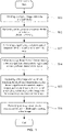
- FIG. 1 is a flowchart of an image adaptive noise reduction method of the present invention.
- FIG. 2 is a processing result of an original image after blocking.
- FIG. 3 is a flowchart of sub-steps according to an embodiment of significance analysis of the present invention.
- FIG. 4 is a significant characteristic diagram obtained after processing a sub-block of the present invention.
- FIG. 5 is a schematic diagram of an algorithm for processing a significant characteristic region according to an embodiment of the present invention.
- FIG. 6 is a structural block diagram of an image adaptive noise reduction device of the present invention.
- first and second are used for descriptive purposes only and are not to be construed as indicating or implying relative importance or implicitly indicating the number of technical features indicated. Thus, features defined as “first”, “second”, may explicitly or implicitly include one or more of the described features.
- plurality means two or more unless specifically limited otherwise.
- including and any variations thereof are intended to cover a non-exclusive inclusion.
- the terms “mounted,” “connected,” and “linked” are to be construed broadly, e.g., as meaning either a fixed connection, a removable connection, or an integral connection; may be mechanically connected, may be electrically connected or may be in communication with each other; either directly or indirectly through intervening media, either internally or in any other relationship.
- the specific meaning of the above terms in the present invention can be understood by those of ordinary skill in the art as appropriate.
- FIG. 1 is a flowchart of an image adaptive noise reduction method of the present invention.
- FIG. 2 is a processing result of an original image after blocking.
- FIG. 3 is a flowchart of sub-steps according to an embodiment of significance analysis of the present invention.
- FIG. 4 is a significant characteristic diagram obtained after processing a sub-block of the present invention.
- FIG. 5 is a schematic diagram of an algorithm for processing a significant characteristic region according to an embodiment of the present invention.
- the present invention provides an image adaptive noise reduction method. Specific steps of the method comprise: S 11 : dividing an original RGB image with noise into a plurality of sub-blocks. S 12 : performing an image space conversion from an RGB space to a YCbCr space for all the sub-blocks. S 13 : performing a significance analysis on each of the sub-blocks to obtain a significant characteristic map after the image space conversion.
- S 15 obtaining a detailed map through a local entropy calculation for each sub-block in the significant characteristic region; performing bilateral filtering on Y channels of all the sub-blocks in the significant characteristic region, and using the detail map to adaptively adjust bilateral filtering results to output first noise reduction images; adjusting channel values of the Y channels of all the sub-blocks in the significant characteristic region through the detail map to output second noise reduction images; mixing the first noise reduction image and the second noise reduction image to obtain a first image, each sub-block in the non-significant characteristic region outputs a second image with original pixel values, and mixing all the first images with the second images to obtain a mixed image.
- S 16 performing an image space inverse conversion from the YCbCr space to the RGB space for the mixed image and outputting a final image.
- step S 11 dividing the original RGB image with noise into the plurality of sub-blocks.
- the image is divided into blocks according to a certain size. Dividing the original RGB image with noise into multiple disjoint sub-blocks of the same size, as shown in FIG. 2 .
- the size of the sub-blocks can be set according to an actual image size and hardware resources. For example, for a 768 ⁇ 512 resolution image, it can be divided into 36 sub-blocks of 96 ⁇ 128 size for post-processing, but it is not limited to the embodiment.
- step S 12 performing the image space conversion from the RGB space to the YCbCr space for all the sub-blocks.
- adopted conversion parameters can be set as:
- step S 13 performing the significance analysis on each of the sub-blocks to obtain the significant characteristic map after the image space conversion.
- step S 13 further comprises:
- the current sub-block is processed into a significant feature map. It can be seen from the significant feature map of the image that the significant feature map has extracted regions of human interest. Due to hardware resource constraints, noise reduction processing can be performed on strong regions of concern, and the hardware resources can be saved by reducing noise reduction in weak regions of interest.
- step S 14 performing the significant threshold segmentation on all the significant characteristic maps by the significant standard value to obtain the significant characteristic region and the non-significant characteristic region.
- significant threshold segmentation is performed on all the significant characteristic maps by a significant standard value ⁇ .
- the significant threshold segmentation is to judge whether the weight threshold of the significant characteristic map of the current operating sub-block is greater than the significant standard value, thereby generating and recording the significant value of the sub-block. All the significant characteristic maps are examined to obtain the significant characteristic region and the non-significant characteristic region. If the weight threshold of the significant map of the current operator sub-block is greater than the significant standard value ⁇ , it is classified into the significant characteristic region, and the significant value R(x) is recorded as 1. Otherwise, it is classified into the non-significant characteristic region, and the significant value R(x) is recorded as 0. As shown in the following formula:
- R ⁇ ( x ) ⁇ 1 if ⁇ ⁇ wNorm ⁇ ( x ) > ⁇ 0 if ⁇ ⁇ wNorm ⁇ ( x ) ⁇ ⁇
- step S 15 outputting the first image after adaptively denoising pixel values of each sub-block in the significant characteristic region, each sub-block in the non-significant characteristic region outputting the second image with original pixel values, and mixing all the first images with the second images to obtain the mixed image.
- the step S 15 further comprises: S 51 : obtaining the detailed map through the local entropy calculation for each sub-block in the significant characteristic region; S 52 : performing bilateral filtering on Y channels of all the sub-blocks in the significant characteristic region, and using the detail map to adaptively adjust bilateral filtering results to output first noise reduction images; S 53 : adjusting the channel values of the Y channels of all the sub-blocks in the significant characteristic region through the detail map to output the second noise reduction images; and S 54 : mixing the first noise reduction image and the second noise reduction image to obtain the first image.
- a value of the local entropy can indicate the amount of detail, the higher the value, the more texture or detail in the region.
- x is the center coordinate of the sub-block
- Pi is a probability of the number of gray levels of a current pixel in the total number of local pixels in a local window ⁇
- i is a gray value of the current pixel
- j is the other gray value
- Hist[i] is a histogram of the gray value of i. that is, the number of i gray levels in the local window ⁇ .
- a size of the local window ⁇ can be set to 5 ⁇ 5 or 7 ⁇ 7.
- the bilateral filtering is calculated by a formula (7):
- I ⁇ ⁇ ( x ) 1 C ⁇ ⁇ y ⁇ N ⁇ ( x ) ⁇ e - ⁇ y - x ⁇ 2 2 ⁇ ⁇ ⁇ d 2 ⁇ e - ⁇ I ⁇ ( y ) - I ⁇ ( x ) ⁇ 2 2 ⁇ ⁇ ⁇ r 2 ⁇ I ⁇ ( y ) ( 7 )
- the pixel difference is small in the flat region, and the corresponding range weight is close to 1.
- Airspace weights play a major role, which is equivalent to directly Gaussian blurring in the region.
- the kernel function is reduced and the current pixel is less affected, thereby maintaining the edge details.
- x is the center coordinate of the sub-block
- R(x) is a significant value of the corresponding sub-block
- E(x) is the local entropy of the corresponding sub-block
- ⁇ (x) is an operation result of the bilateral filtering
- Y in (x) is a channel value of an input of the Y channel.
- the detail map of the output image obtained from local entropy adaptively adjusts bilateral filtering.
- the output image mainly depends on the Y channel through the original image.
- the output image mainly depends on the filtered image.
- the output is the original pixel value.
- step S 16 performing the image space inverse conversion from the YCbCr space to the RGB space for the mixed image and outputting the final image.
- the conversion parameters adopted are set to:
- Image block significance analysis method can be applied to other noise reduction algorithms and has universality.
- FIG. 6 is a structural block diagram of an image adaptive noise reduction device of the present invention.
- the invention further discloses an image adaptive noise reduction device, comprising: an image division module 61 , an image space conversion module 62 , a significance analysis module 63 , a significant segmentation module 64 , an image output module 65 , and an image space inverse conversion module 66 .
- the image division module 61 is for dividing an original RGB image with noise into a plurality of sub-blocks. Specifically, the image division module 61 divides the image into blocks according to a certain size, and divides the original RGB image with noise into multiple disjoint sub-blocks of the same size. The size of the sub-block can be set according to the actual image size and hardware resources.
- the image space conversion module 62 is for performing an image space conversion from an RGB space to a YCbCr space on all the sub-blocks.
- the image space conversion module 62 can perform matrix operations, and the conversion parameters used can be set to:
- the significance analysis module 63 is for performing a significance analysis on each of the sub-blocks to obtain a significant characteristic map after the image space conversion.
- the significance analysis module 63 obtains channel values of the Y, Cb, and Cr channels of each of the sub-blocks, respectively. According to the obtained channel values, the channel averages of the three channels Y, Cb, and Cr are respectively calculated, and the Euclidean distances of the channel values of the Y, Cb, and Cr of each of the sub-blocks and the corresponding channel averages are respectively calculated as significant weight. Normalize each of the significant weights to obtain a corresponding weight normalization value, and then obtain the significant characteristic map.
- the significant segmentation module 64 is for performing a threshold segmentation on all the significant characteristic maps by a significant standard value to obtain a significant characteristic region and a non-significant characteristic region.
- the significant segmentation module 64 determines whether the weight threshold of the significant characteristic map of the current operation sub-block is greater than the significant standard value. If the weight threshold is greater than the significant standard value, the currently processed one of the sub-blocks is classified into a significant characteristic region, otherwise the currently processed one of the sub-blocks is classified into a non-significant characteristic region, and significant values of the sub-blocks are generated and recorded. All the significant characteristic maps are traversed to obtain the significant characteristic region and the non-significant characteristic region.
- the image output module 65 is for performing adaptive noise reduction on pixel values of the sub-blocks in the significant characteristic region to output first images, controlling each the sub-block in the non-significant characteristic region to output a second image with an original pixel value, and mixing the first image and the second image to obtain a mixed image.
- the image output module 65 is further configured to: obtaining a detailed map through a local entropy calculation for each sub-block in the significant characteristic region; performing bilateral filtering on Y channels of all the sub-blocks in the significant characteristic region, and using the detail map to adaptively adjust the bilateral filtering results to output first noise reduction images; adjusting channel values of the Y channels of all the sub-blocks in the significant characteristic region through the detail map to output second noise reduction images; and mixing the first noise reduction images with the second noise reduction images to obtain the first image.
- the image space inverse conversion module 66 is for inversely converting the mixed image from the YCbCr space to the RGB space and outputting a final image.
- the image space inverse conversion module 66 may perform matrix operations, and the conversion parameters adopted are set to:
- the image adaptive noise reduction method of the present invention can be applied to display terminals, and the display terminals may be smart phones, tablet computers, televisions, and other devices.
- the display terminals comprise processors and memories that are electrically connected to each other.
- the processors are control centers of the display terminals.
- the processors use various interfaces and lines to connect various parts of the entire display terminals.
- the processors run or load applications stored in the memories, and call data stored in the memories to perform various functions of the display terminals and process data to monitor the display terminal as a whole.
- the processors in the display terminals load the instructions corresponding to the process of one or more application programs into the memories according to the steps in the image adaptive noise reduction method of the present invention, and the processors run the application program stored in the memories, so as to realize various functions.
- an embodiment of the present invention provides a storage medium in which a plurality of instructions are stored, and the instructions can be loaded by the processors to execute the steps in any of the image adaptive noise reduction methods provided by the embodiments of the present invention.
- the storage mediums may include: read-only memory (ROM), random access memory (RAM), magnetic disk or optical disk, etc.
Abstract
Description
-
- wherein N is a total number of the sub-blocks;
w(x)=∥(Y(x),Cb(x),Cr(x))−(Y ave ,Cb ave ,Cr ave)∥2 (4)
-
- wherein wMax is a maximum of all the significant weights, and x is the center coordinate of the sub-block.
-
- Wherein, α∈[0,1], the value of a is related to specific hardware resources. In the embodiment, α=0.6.
E(x)=−Σi=0 255 P i logP i (6)
x is the center coordinate of the sub-block; Pi is a probability of the number of gray levels of a current pixel in the total number of local pixels in a local window Ω; i is a gray value of the current pixel; j is the other gray value; Hist[i] is a histogram of the gray value of i. that is, the number of i gray levels in the local window Ω. A size of the local window Ω can be set to 5×5 or 7×7.
x is the center coordinate of the sub-block; y is the other coefficient coordinates of a template window; I(x) and I(y) represent pixel values corresponding to the coordinates; N(x) is a neighborhood of pixel (x); C is a normalization constant; σd is a standard deviation of a geometric distance, and σr is a standard deviation of a gray distance, which respectively control the attenuation rate of two geometric distances and gray distances. In the bilateral filtering, the pixel difference is small in the flat region, and the corresponding range weight is close to 1. Airspace weights play a major role, which is equivalent to directly Gaussian blurring in the region. In an edge region, the larger the pixel difference is, the lower the range coefficient is. As a result, the kernel function is reduced and the current pixel is less affected, thereby maintaining the edge details.
Y out(x)=R(x)×(E(x)×I(x)+(1−E))×Y in(x))+(1−R(x))×Y in(x) (8)
Claims (17)
w(x)=∥(Y(x),Cb(x),Cr(x))−(Y ave ,Cb ave ,Cr ave)∥2 (4)
E(x)=−Σi=0 255 P i logP i (6)
Y out(x)=R(x)×(E(x)×I(x)+(1−E))×Y in(x))+(1−R(x))×Y in(x) (8)
w(x)=∥(Y(x),Cb(x),Cr(x))−(Y ave ,Cb ave ,Cr ave)∥2 (4)
E(x)=−Σi=0 255 P i logP i (6)
Y out(x)=R(x)×(E(x)×I(x)+(1−E))×Y in(x))+(1−R(x))×Y in(x) (8)
Applications Claiming Priority (3)
| Application Number | Priority Date | Filing Date | Title |
|---|---|---|---|
| CN201911352759.5A CN111161177B (en) | 2019-12-25 | 2019-12-25 | Image self-adaptive noise reduction method and device |
| CN201911352759.5 | 2019-12-25 | ||
| PCT/CN2020/071307 WO2021128498A1 (en) | 2019-12-25 | 2020-01-10 | Image adaptive noise reduction method and apparatus |
Publications (2)
| Publication Number | Publication Date |
|---|---|
| US20220051368A1 US20220051368A1 (en) | 2022-02-17 |
| US11348204B2 true US11348204B2 (en) | 2022-05-31 |
Family
ID=70556545
Family Applications (1)
| Application Number | Title | Priority Date | Filing Date |
|---|---|---|---|
| US16/646,054 Active 2040-08-11 US11348204B2 (en) | 2019-12-25 | 2020-01-10 | Image adaptive noise reduction method and device thereof |
Country Status (3)
| Country | Link |
|---|---|
| US (1) | US11348204B2 (en) |
| CN (1) | CN111161177B (en) |
| WO (1) | WO2021128498A1 (en) |
Families Citing this family (2)
| Publication number | Priority date | Publication date | Assignee | Title |
|---|---|---|---|---|
| CN113763275A (en) * | 2021-09-09 | 2021-12-07 | 深圳市文立科技有限公司 | Adaptive image noise reduction method and system and readable storage medium |
| CN117576139B (en) * | 2024-01-17 | 2024-04-05 | 深圳市致佳仪器设备有限公司 | Edge and corner detection method and system based on bilateral filtering |
Citations (6)
| Publication number | Priority date | Publication date | Assignee | Title |
|---|---|---|---|---|
| US20100111414A1 (en) * | 2007-06-25 | 2010-05-06 | Olympus Corporation | Image processing device, image processing method, and computer-readable storage medium storing image processing program |
| US8457433B2 (en) * | 2010-01-28 | 2013-06-04 | Texas Instruments Incorporated | Methods and systems for image noise filtering |
| US20170061582A1 (en) * | 2015-08-31 | 2017-03-02 | Apple Inc. | Temporal filtering of independent color channels in image data |
| US20170061234A1 (en) * | 2015-08-31 | 2017-03-02 | Apple Inc. | Noise filtering and image sharpening utilizing common spatial support |
| US20170070718A1 (en) * | 2015-09-04 | 2017-03-09 | Apple Inc. | Advanced Multi-Band Noise Reduction |
| US20170318240A1 (en) * | 2016-05-02 | 2017-11-02 | Qualcomm Incorporated | Methods and apparatus for automated noise and texture optimization of digital image sensors |
Family Cites Families (14)
| Publication number | Priority date | Publication date | Assignee | Title |
|---|---|---|---|---|
| TWI387312B (en) * | 2008-10-28 | 2013-02-21 | Novatek Microelectronics Corp | Image noise reduction method and processor |
| US7983511B1 (en) * | 2010-11-29 | 2011-07-19 | Adobe Systems Incorporated | Methods and apparatus for noise reduction in digital images |
| CN102663714B (en) * | 2012-03-28 | 2014-06-25 | 中国人民解放军国防科学技术大学 | Saliency-based method for suppressing strong fixed-pattern noise in infrared image |
| CN103679661B (en) * | 2013-12-25 | 2016-09-28 | 北京师范大学 | A kind of self adaptation remote sensing image fusion method based on significance analysis |
| CN104751415B (en) * | 2013-12-31 | 2017-12-26 | 展讯通信(上海)有限公司 | The method, apparatus and image processing system of a kind of image noise reduction and enhancement |
| US9911179B2 (en) * | 2014-07-18 | 2018-03-06 | Dolby Laboratories Licensing Corporation | Image decontouring in high dynamic range video processing |
| US9852353B2 (en) * | 2014-11-12 | 2017-12-26 | Adobe Systems Incorporated | Structure aware image denoising and noise variance estimation |
| CN106296638A (en) * | 2015-06-04 | 2017-01-04 | 欧姆龙株式会社 | Significance information acquisition device and significance information acquisition method |
| CN104978718A (en) * | 2015-06-12 | 2015-10-14 | 中国科学院深圳先进技术研究院 | Video raindrop removing method and system based on image entropy |
| CN104978720A (en) * | 2015-07-01 | 2015-10-14 | 深圳先进技术研究院 | Video image raindrop removal method and apparatus |
| CN105243652B (en) * | 2015-11-19 | 2019-06-07 | Tcl集团股份有限公司 | The method and device of image noise reduction |
| CN105957054B (en) * | 2016-04-20 | 2019-03-19 | 北京航空航天大学 | A kind of image change detection method |
| CN109389560B (en) * | 2018-09-27 | 2022-07-01 | 深圳开阳电子股份有限公司 | Adaptive weighted filtering image noise reduction method and device and image processing equipment |
| CN109754374A (en) * | 2018-12-20 | 2019-05-14 | 深圳市资福医疗技术有限公司 | A kind of method and device removing brightness of image noise |
-
2019
- 2019-12-25 CN CN201911352759.5A patent/CN111161177B/en active Active
-
2020
- 2020-01-10 WO PCT/CN2020/071307 patent/WO2021128498A1/en active Application Filing
- 2020-01-10 US US16/646,054 patent/US11348204B2/en active Active
Patent Citations (6)
| Publication number | Priority date | Publication date | Assignee | Title |
|---|---|---|---|---|
| US20100111414A1 (en) * | 2007-06-25 | 2010-05-06 | Olympus Corporation | Image processing device, image processing method, and computer-readable storage medium storing image processing program |
| US8457433B2 (en) * | 2010-01-28 | 2013-06-04 | Texas Instruments Incorporated | Methods and systems for image noise filtering |
| US20170061582A1 (en) * | 2015-08-31 | 2017-03-02 | Apple Inc. | Temporal filtering of independent color channels in image data |
| US20170061234A1 (en) * | 2015-08-31 | 2017-03-02 | Apple Inc. | Noise filtering and image sharpening utilizing common spatial support |
| US20170070718A1 (en) * | 2015-09-04 | 2017-03-09 | Apple Inc. | Advanced Multi-Band Noise Reduction |
| US20170318240A1 (en) * | 2016-05-02 | 2017-11-02 | Qualcomm Incorporated | Methods and apparatus for automated noise and texture optimization of digital image sensors |
Also Published As
| Publication number | Publication date |
|---|---|
| US20220051368A1 (en) | 2022-02-17 |
| WO2021128498A1 (en) | 2021-07-01 |
| CN111161177B (en) | 2023-09-26 |
| CN111161177A (en) | 2020-05-15 |
Similar Documents
| Publication | Publication Date | Title |
|---|---|---|
| US9576346B2 (en) | Non-local means image denoising with an adaptive directional spatial filter | |
| US9489720B2 (en) | Non-local means image denoising with detail preservation using self-similarity driven blending | |
| US7657114B2 (en) | Data processing apparatus, data processing method, and program | |
| US20100278423A1 (en) | Methods and systems for contrast enhancement | |
| US10963995B2 (en) | Image processing apparatus and image processing method thereof | |
| US8244054B2 (en) | Method, apparatus and integrated circuit capable of reducing image ringing noise | |
| US11348204B2 (en) | Image adaptive noise reduction method and device thereof | |
| US8131104B2 (en) | Method and apparatus for adjusting the contrast of an input image | |
| EP3379817A1 (en) | Method for real-time video noise reduction in coding process, terminal, and nonvolatile computer readable storage medium | |
| US9025903B2 (en) | Image processing device and image processing method | |
| US20080279279A1 (en) | Content adaptive motion compensated temporal filter for video pre-processing | |
| CN105006001B (en) | A kind of method for evaluating quality for having ginseng image based on nonlinear organization similarity deviation | |
| CN111988611A (en) | Method for determining quantization offset information, image coding method, image coding device and electronic equipment | |
| CN109255752B (en) | Image self-adaptive compression method, device, terminal and storage medium | |
| CN107292834B (en) | Infrared image detail enhancement method | |
| CN103971345A (en) | Image denoising method based on improved bilateral filtering | |
| Wei et al. | Visual saliency based perceptual video coding in HEVC | |
| CN112950491B (en) | Video processing method and device | |
| CN112150368A (en) | Image processing method, image processing device, electronic equipment and computer readable storage medium | |
| US11915392B2 (en) | Image enhancement method and apparatus | |
| US20180114297A1 (en) | Systems and methods for image noise reduction | |
| CN111724325B (en) | Trilateral filtering image processing method and trilateral filtering image processing device | |
| US20210352299A1 (en) | Image and video data processing method and system | |
| CN115802038A (en) | Quantization parameter determination method and device and video coding method and device | |
| US11528488B2 (en) | Image and video data processing method and system |
Legal Events
| Date | Code | Title | Description |
|---|---|---|---|
| FEPP | Fee payment procedure |
Free format text: ENTITY STATUS SET TO UNDISCOUNTED (ORIGINAL EVENT CODE: BIG.); ENTITY STATUS OF PATENT OWNER: LARGE ENTITY |
|
| AS | Assignment |
Owner name: TCL CHINA STAR OPTOELECTRONICS TECHNOLOGY CO., LTD., CHINA Free format text: ASSIGNMENT OF ASSIGNORS INTEREST;ASSIGNOR:CHEN, YUNNA;REEL/FRAME:054663/0244 Effective date: 20191220 |
|
| STPP | Information on status: patent application and granting procedure in general |
Free format text: NON FINAL ACTION MAILED |
|
| STPP | Information on status: patent application and granting procedure in general |
Free format text: RESPONSE TO NON-FINAL OFFICE ACTION ENTERED AND FORWARDED TO EXAMINER |
|
| STPP | Information on status: patent application and granting procedure in general |
Free format text: NOTICE OF ALLOWANCE MAILED -- APPLICATION RECEIVED IN OFFICE OF PUBLICATIONS |
|
| STPP | Information on status: patent application and granting procedure in general |
Free format text: PUBLICATIONS -- ISSUE FEE PAYMENT VERIFIED |
|
| STCF | Information on status: patent grant |
Free format text: PATENTED CASE |