US11340975B2 - System monitor - Google Patents
System monitor Download PDFInfo
- Publication number
- US11340975B2 US11340975B2 US16/794,067 US202016794067A US11340975B2 US 11340975 B2 US11340975 B2 US 11340975B2 US 202016794067 A US202016794067 A US 202016794067A US 11340975 B2 US11340975 B2 US 11340975B2
- Authority
- US
- United States
- Prior art keywords
- fault
- state
- monitoring circuit
- data frame
- examples
- Prior art date
- Legal status (The legal status is an assumption and is not a legal conclusion. Google has not performed a legal analysis and makes no representation as to the accuracy of the status listed.)
- Active, expires
Links
Images


Classifications
-
- G—PHYSICS
- G06—COMPUTING OR CALCULATING; COUNTING
- G06F—ELECTRIC DIGITAL DATA PROCESSING
- G06F1/00—Details not covered by groups G06F3/00 - G06F13/00 and G06F21/00
- G06F1/26—Power supply means, e.g. regulation thereof
- G06F1/32—Means for saving power
- G06F1/3203—Power management, i.e. event-based initiation of a power-saving mode
- G06F1/3234—Power saving characterised by the action undertaken
- G06F1/3296—Power saving characterised by the action undertaken by lowering the supply or operating voltage
-
- G—PHYSICS
- G06—COMPUTING OR CALCULATING; COUNTING
- G06F—ELECTRIC DIGITAL DATA PROCESSING
- G06F11/00—Error detection; Error correction; Monitoring
- G06F11/07—Responding to the occurrence of a fault, e.g. fault tolerance
- G06F11/0703—Error or fault processing not based on redundancy, i.e. by taking additional measures to deal with the error or fault not making use of redundancy in operation, in hardware, or in data representation
- G06F11/0706—Error or fault processing not based on redundancy, i.e. by taking additional measures to deal with the error or fault not making use of redundancy in operation, in hardware, or in data representation the processing taking place on a specific hardware platform or in a specific software environment
- G06F11/0721—Error or fault processing not based on redundancy, i.e. by taking additional measures to deal with the error or fault not making use of redundancy in operation, in hardware, or in data representation the processing taking place on a specific hardware platform or in a specific software environment within a central processing unit [CPU]
-
- G—PHYSICS
- G06—COMPUTING OR CALCULATING; COUNTING
- G06F—ELECTRIC DIGITAL DATA PROCESSING
- G06F11/00—Error detection; Error correction; Monitoring
- G06F11/07—Responding to the occurrence of a fault, e.g. fault tolerance
- G06F11/0703—Error or fault processing not based on redundancy, i.e. by taking additional measures to deal with the error or fault not making use of redundancy in operation, in hardware, or in data representation
- G06F11/0706—Error or fault processing not based on redundancy, i.e. by taking additional measures to deal with the error or fault not making use of redundancy in operation, in hardware, or in data representation the processing taking place on a specific hardware platform or in a specific software environment
- G06F11/0736—Error or fault processing not based on redundancy, i.e. by taking additional measures to deal with the error or fault not making use of redundancy in operation, in hardware, or in data representation the processing taking place on a specific hardware platform or in a specific software environment in functional embedded systems, i.e. in a data processing system designed as a combination of hardware and software dedicated to performing a certain function
- G06F11/0739—Error or fault processing not based on redundancy, i.e. by taking additional measures to deal with the error or fault not making use of redundancy in operation, in hardware, or in data representation the processing taking place on a specific hardware platform or in a specific software environment in functional embedded systems, i.e. in a data processing system designed as a combination of hardware and software dedicated to performing a certain function in a data processing system embedded in automotive or aircraft systems
-
- G—PHYSICS
- G06—COMPUTING OR CALCULATING; COUNTING
- G06F—ELECTRIC DIGITAL DATA PROCESSING
- G06F11/00—Error detection; Error correction; Monitoring
- G06F11/07—Responding to the occurrence of a fault, e.g. fault tolerance
- G06F11/0703—Error or fault processing not based on redundancy, i.e. by taking additional measures to deal with the error or fault not making use of redundancy in operation, in hardware, or in data representation
- G06F11/0751—Error or fault detection not based on redundancy
- G06F11/0754—Error or fault detection not based on redundancy by exceeding limits
- G06F11/0757—Error or fault detection not based on redundancy by exceeding limits by exceeding a time limit, i.e. time-out, e.g. watchdogs
-
- G—PHYSICS
- G06—COMPUTING OR CALCULATING; COUNTING
- G06F—ELECTRIC DIGITAL DATA PROCESSING
- G06F11/00—Error detection; Error correction; Monitoring
- G06F11/07—Responding to the occurrence of a fault, e.g. fault tolerance
- G06F11/0703—Error or fault processing not based on redundancy, i.e. by taking additional measures to deal with the error or fault not making use of redundancy in operation, in hardware, or in data representation
- G06F11/0766—Error or fault reporting or storing
- G06F11/0772—Means for error signaling, e.g. using interrupts, exception flags, dedicated error registers
-
- G—PHYSICS
- G06—COMPUTING OR CALCULATING; COUNTING
- G06F—ELECTRIC DIGITAL DATA PROCESSING
- G06F13/00—Interconnection of, or transfer of information or other signals between, memories, input/output devices or central processing units
- G06F13/38—Information transfer, e.g. on bus
- G06F13/40—Bus structure
- G06F13/4004—Coupling between buses
- G06F13/4027—Coupling between buses using bus bridges
-
- G—PHYSICS
- G01—MEASURING; TESTING
- G01R—MEASURING ELECTRIC VARIABLES; MEASURING MAGNETIC VARIABLES
- G01R31/00—Arrangements for testing electric properties; Arrangements for locating electric faults; Arrangements for electrical testing characterised by what is being tested not provided for elsewhere
- G01R31/005—Testing of electric installations on transport means
- G01R31/006—Testing of electric installations on transport means on road vehicles, e.g. automobiles or trucks
- G01R31/007—Testing of electric installations on transport means on road vehicles, e.g. automobiles or trucks using microprocessors or computers
-
- G—PHYSICS
- G01—MEASURING; TESTING
- G01R—MEASURING ELECTRIC VARIABLES; MEASURING MAGNETIC VARIABLES
- G01R31/00—Arrangements for testing electric properties; Arrangements for locating electric faults; Arrangements for electrical testing characterised by what is being tested not provided for elsewhere
- G01R31/36—Arrangements for testing, measuring or monitoring the electrical condition of accumulators or electric batteries, e.g. capacity or state of charge [SoC]
- G01R31/371—Arrangements for testing, measuring or monitoring the electrical condition of accumulators or electric batteries, e.g. capacity or state of charge [SoC] with remote indication, e.g. on external chargers
Definitions
- the monitoring allows for system performance and/or analytics reporting, enforcement of safety mechanisms (e.g., such as turn-off or forced reduction in performance if monitored conditions exceed permitted thresholds), trimming or tuning of system performance, etc.
- Some approaches to this monitoring include constant polling to obtain data. However, this approach can be expensive from perspectives of both communication bandwidth consumption and power consumption and can result in an extended fault detection time interval.
- Other approaches to this monitoring include the inclusion of dedicated fault detection hardware that is daisy chained between devices so that a fault signal is forwarded to a controller through the daisy chain. However, this approach can also be expensive due to a requirement for additional components and couplings and due to power consumed, because at least some implementations of this approach prevent the controller from being placed in a low-power mode (e.g., idle or shutdown).
- the circuit includes a microcontroller and a communication bridge.
- the communication bridge is coupled to the microcontroller and configured to implement a state machine.
- the state machine comprises a first state configured to receive a data frame comprising data and a second state configured to determine whether a system fault is indicated in the data frame. The first state transitions to the second state when the data frame is received.
- the state machine further comprises a third state configured to assert a fault signal when the system fault is indicated in the data frame.
- the second state transitions to the third state when the system fault is indicated in the data frame.
- the state machine further comprises a fourth state configured to transmit the data from the data frame to the microcontroller. The third state transitions to the fourth state after asserting the fault signal.
- the circuit includes a register and a monitoring circuit coupled to the register and configured to implement a state machine.
- the state machine comprises a first state configured to generate a data frame including at least some data from the register and a second state configured to determine a system fault status. The first state transitions to the second state after generating the data frame.
- the state machine further comprises a third state configured to set a fault status indication of the data frame when a fault exists in the system. The second state transitions to the third state when the monitoring circuit detects a fault.
- the state machine further comprises a fourth state configured to transmit the data frame to a next device. The second state transitions to the fourth state when the monitoring circuit does not detect a fault.
- the third state transitions to the fourth state after setting the fault status indication of the data frame.
- the system includes a microcontroller, an energy storage element, a monitoring circuit, and a communication bridge.
- the monitoring circuit is coupled to the energy storage element and configured to determine whether a fault associated with the energy storage element is present, generate an indication of the fault when the fault with the energy storage element is present, and transmit the indication of the fault.
- the communication bridge is configured to receive the indication of the fault and assert a fault signal and transmit the fault signal to the microcontroller.
- FIG. 1 shows a block diagram of an illustrative system in accordance with various examples
- FIG. 2 shows a schematic diagram of an illustrative data frame in accordance with various examples
- FIG. 3 shows a timing diagram of signal generation in a system in accordance with various examples
- FIG. 4 shows a flowchart of an illustrative method in accordance with various examples
- FIG. 5 shows a flowchart of an illustrative method in accordance with various examples
- FIG. 6 shows a flowchart of an illustrative method in accordance with various examples
- FIG. 7 shows a flowchart of an illustrative method in accordance with various examples
- FIG. 8 is a diagram of an illustrative state machine in accordance with various examples.
- FIG. 9 is a diagram of an illustrative state machine in accordance with various examples.
- FIG. 10 is a diagram of an illustrative state machine in accordance with various examples.
- FIG. 11 is a diagram of an illustrative state machine in accordance with various examples.
- FIG. 12 is a diagram of an illustrative state machine in accordance with various examples.
- a status of the energy storage cells e.g., batteries
- monitoring the batteries can provide an indication of a voltage of the batteries, temperatures, the existence of a fault, etc. This information can then in turn be used for decision making regarding the energy storage system, such as shutting down the system, reducing performance of the system, bypassing portions of the system, generating a notice that the system requires service, etc.
- communication exists between a controller, such as a microcontroller, microprocessor, or other processing device and one or more monitor units. This communication includes one or more pieces of data, in at least some examples arranged in data frames, each of which includes a plurality of bytes of data.
- these frames of data include data bits that are ignored, unnecessary, redundant, or otherwise unused.
- each byte of the data frame follows a same general format that includes a start of frame (SOF) data bit.
- SOF start of frame
- the SOF data bits of subsequent bytes of the data frame are then unused with respect to containing meaningful data and are unutilized overhead.
- at least some implementations of the system monitor of the present disclosure repurpose the SOF data bit of at least some of the subsequent bytes of the data frame to indicate a fault status in a system.
- a value of the SOF data bit of one byte, two bytes, three bytes, etc. may indicate the fault status.
- reuse of the SOF data bit as described herein has certain benefits with regard to backward compatibility (e.g., not requiring support for a different length data frame) that make use of the SOF data bit advantageous over other data bits.
- backward compatibility e.g., not requiring support for a different length data frame
- repurposing of otherwise unused SOF data bits enables support for fault detection and reporting/notification in existing communication data frames without adding additional data bits and/or bytes to the data frame for the purpose of performing the fault detection and/or reporting/notification.
- any suitable bit(s) of any suitable byte(s) of a data frame may be repurposed to indicate a fault status in a system, or, alternatively, no data bits may be repurposed and new data bit(s) and/or byte(s) may be added to support fault reporting functionality.
- a controller communicates (e.g., a command frame) with a first monitor, which communicates with a second monitor, and so forth until a final monitor in a daisy chain of monitors communicates back to the controller.
- the communication from the monitor back to the controller (e.g., a response frame), in at least some examples, follows the same communication links in a reverse order that the communication from the controller to the monitor followed.
- the controller communicates with a monitor along the daisy chain of monitors without communication back to the controller (e.g., such as when no response to the controller is necessary).
- the monitor has an opportunity to alter the data frame, such as to indicate a fault in that monitor.
- a fault status can be indicated in the data frame.
- the fault status can be indicated in a command frame or in a response frame (each of which is collectively referred to hereinafter as a data frame).
- a monitor in the daisy chain copies the indication to a response frame.
- the fault indication included in the SOF data bit only indicates an existence of a fault in the system and not a nature of the fault or a location of the fault.
- other information may be provided, such as a device address of a monitor reporting the fault, a nature or type of the fault, etc.
- a value of the SOF data bit of one byte, two bytes, three bytes, etc. may indicate the fault status.
- a monitor reporting a fault sets the SOF data bit of one byte of the data frame to a logical 1.
- the monitor provides data redundancy by setting the SOF data bit of more than one byte to a logical 1. In this way, if a portion of the data frame including an SOF data bit set to indicate a fault is corrupted prior to receipt by the controller, the controller retains an ability to determine the existence of the fault through a redundantly set SOF data bit of another byte of the data frame.
- which byte has a SOF data bit set to a logical 1 may be determined by a type of fault being reported (e.g., a temperature fault reported via a SOF data bit of one byte, a voltage fault reported via a SOF data bit of another byte, etc.).
- a type of fault e.g., a temperature fault reported via a SOF data bit of one byte, a voltage fault reported via a SOF data bit of another byte, etc.
- a communication bridge exists between the monitors and the controller.
- the communication bridge receives and processes the data frame from the monitors, generating a fault output signal when a SOF data bit of the data frame indicates an existence of a fault.
- the fault output signal is provided to the controller by the bridge device.
- the controller when the bridge device outputs the fault output signal, the controller is in a low-power state such that the controller is idle, shutdown, or otherwise in a state that prevents the controller from receiving the fault output signal.
- the communication bridge further generates and outputs a trigger signal.
- the trigger signal in at least some examples, causes the controller to exit the low-power state.
- the trigger signal causes the controller to exit the low-power state, in some examples, by causing a power management component to provide power to the controller.
- the trigger signal is received by the controller and causes the controller to exit the low-power state. When the controller exits the low-power state, the controller receives the fault output signal that was output by the communication bridge.
- the bridge outputs a heartbeat signal in place of the data frame.
- the heartbeat signal is output, in some examples, periodically, such as about every 400 milliseconds.
- the heartbeat signal progresses through the daisy chain of monitors and back to the communication bridge. For example, a monitor receives the heartbeat tone and generates another heartbeat tone that is forwarded to an upstream monitor in the daisy chain until a final monitor in the daisy chain transmits the heartbeat tone to the communication bridge.
- one of the monitors does not receive the heartbeat tone, does not receive the heartbeat tone within a predetermined or expected period of time, or detects a fault, that respective monitor generates and transmits a fault tone in place of the heartbeat tone.
- the communication bridge does not receive the heartbeat tones for a predetermined period of time (e.g., such as about 1 second, indicating that two heartbeat tones have been missed), the communication bridge determines that a fault exists and outputs the fault output signal and/or the trigger signal.
- the communication bridge receives a fault tone instead of a heartbeat tone, the communication bridge determines that a fault exists and outputs the fault output signal and/or the trigger signal.
- a management unit (e.g., that includes the controller and/or the bridge) transmits the data frame to a monitor coupled to the management unit.
- the data frame is forwarded through one or more monitors via a daisy chain until it reaches a last monitor in the daisy chain, or a monitor to which the data frame is addressed.
- a response frame is then transmitted back to the management unit from one of the monitors in the daisy chain.
- communication couplings can be damaged or break. In some of the alternative approaches to system monitoring, this can entirely prevent any future monitoring until the damaged coupling is repaired or replaced, if either of those options is available.
- the system monitor of the present disclosure when a break is detected, retains an ability to communicate and detect faults.
- the management unit transmits two data frames—one to the first monitor in a daisy chain and one to the last monitor in the daisy chain. The data frames then progress through the daisy chain of monitors from one or both ends of the daisy chain until reaching the broken or damaged coupling. In this way, the management unit retains an ability to communicate with, and detect faults in, a system despite damage to a communication coupling in the system.
- the controller polls the monitors (e.g., sends data frames addressed to each monitor requesting data from the specifically addressed monitor) to learn more information about the fault, such as a location of the fault, nature of the fault, etc.
- the system 100 is representative of an energy storage system.
- the system 100 is representative of at least a portion of a hybrid or electric vehicle (whether land, air, or sea and manner, semi-autonomous, or fully-autonomous), such as a sub-system of the hybrid or electric vehicle.
- a hybrid or electric vehicle whether land, air, or sea and manner, semi-autonomous, or fully-autonomous
- the system 100 are representative of a powertrain sub-system of a vehicle and/or a power sub-system of a vehicle.
- the system 100 is representative of any system in which one or more components are monitored by one or more monitors that communicate with a management unit and/or controller.
- the components being monitored may be batteries, sensors, circuits, circuit components, articulating components, etc., or any combinations thereof.
- the system 100 monitors multiple different types of components (e.g., the system 100 may monitor both batteries and sensors, etc.).
- the system 100 includes, in some examples, a management unit 102 , a monitoring unit 104 , and a monitoring unit 106 .
- the system 100 further includes, or is configured to couple to, a component 108 , a component 110 , a component 112 , and a component 114 .
- each of the component 108 , the component 110 , the component 112 , and the component 114 are energy storage elements, such as batteries.
- any one or more of the component 108 , the component 110 , the component 112 , or the component 114 are any other suitable component being monitored by the system 100 . While the system 100 includes only two monitoring units, each monitoring two components, in various examples, the system 100 includes any number of monitoring units coupled together, each of which monitors any number of components.
- the management unit 102 includes a communication bridge 116 , a microcontroller 118 , and a power management component 120 .
- the power management component 120 controls the providing of power to the microcontroller 118 and, in some examples, the communication bridge 116 .
- the power management component 120 couples to a node 121 at which an input voltage (VIN) is present and further couples to a VIN terminal of the communication bridge 116 .
- the communication bridge 116 includes a first communication interface (interfaces not expressly depicted) configured to couple to the monitoring unit 104 and a second communication interface configured to couple to the monitoring unit 106 .
- the communication bridge 116 further includes one or more couplings with the microcontroller 118 to facilitate data flow between the communication bridge 116 and the microcontroller 118 .
- one or more components such as isolation components, are coupled to one or more ends of the couplings within the system 100 .
- Data transmitted between the communication bridge 116 and the microcontroller 118 can include the fault output signal, as discussed elsewhere herein, data for inclusion in a data frame to be output by the communication bridge 116 , data received by the communication bridge 116 in a data frame, or any other suitable data.
- the communication bridge 116 is further coupled to the power management component 120 .
- the communication bridge 116 is coupled to an enable input of the power management component 120 such that an asserted output signal of the communication bridge 116 causes the power management component 120 to become enabled and provide power to the microcontroller 118 .
- the communication bridge 116 includes one or more components capable of, or suitable for, performing logical operations.
- the communication bridge 116 include components suitable for performing logical operations to implement a state machine.
- the communication bridge 116 is a state machine circuit that implements one or more state machines.
- the communication bridge 116 is alternatively, or additionally, referred to as an integrated circuit.
- Various implementations of the communication bridge 116 include additional functionality not described herein, where that additional functionality is controlled and/or implemented through one or more additional state machines.
- the communication bridge 116 implements a state machine to perform functions of the present disclosure, such as detection, in a received data frame, of an indication of a fault and generation of the fault output signal based on such detection.
- the state machine or alternatively another state machine, performs other functions of the present disclosure, such as output of, and monitoring for, a heartbeat signal and generation of the fault output signal and trigger signal based on a predetermined number of heartbeat signals not being detected or a heartbeat signal not being detected for a predetermined period of time.
- the monitoring unit 104 includes a monitoring circuit 122 , a storage element 123 , and a monitoring circuit 124 .
- the monitoring unit 106 includes a monitoring circuit 126 , a storage element 127 , and a monitoring circuit 128 . While each monitoring unit of the system 100 is illustrated as including two monitoring circuits, in in at least some examples, one or more of the monitoring units includes fewer, or more, monitoring circuits. Additionally, while each monitoring unit of the system 100 is illustrated as including one storage element, in other examples, either monitoring unit may include additional storage elements. Additionally, in at least some examples, the storage elements may be implemented as components of a respective monitoring circuit.
- the storage element 123 and the storage element 127 each comprise a plurality of registers configured to store data.
- the monitoring circuit 122 and/or the monitoring circuit 124 interact with the storage element 123 to read data from, or write data to, the storage element 123 .
- the monitoring circuit 126 and/or the monitoring circuit 128 interact with the storage element 127 to read data from, or write data to, the storage element 127 .
- the monitoring circuit 122 is coupled to the communication bridge 116 , the monitoring circuit 124 , and the storage element 123 .
- the monitoring circuit 122 is further coupled to the component 108 and configured to monitor the component 108 .
- the monitoring circuit 124 is coupled to the monitoring circuit 122 , the monitoring circuit 126 , and the storage element 123 .
- the monitoring circuit 124 is further coupled to the component 110 and configured to monitor the component 110 .
- the monitoring circuit 126 is coupled to the monitoring circuit 124 , the monitoring circuit 128 , and the storage element 127 .
- the monitoring circuit 126 is further coupled to the component 112 and configured to monitor the component 112 .
- the monitoring circuit 128 is coupled to the monitoring circuit 126 , the communication bridge 116 , and the storage element 127 .
- the monitoring circuit 128 is further coupled to the component 114 and configured to monitor the component 114 .
- the couplings in the system 100 are illustrated as two-wire couplings (e.g., such as couplings between the management unit 102 , the monitoring unit 104 , and the monitoring unit 106 , and within the monitoring unit 104 and the monitoring unit 106 ), in other examples, the couplings are single-wire.
- one or more additional components are coupled in-line between a respective monitoring circuit and the component to which the monitoring circuit is coupled.
- the communication bridge 116 outputs a data frame to the monitoring circuit 122 .
- the data frame includes data received by the communication bridge 116 from the microcontroller 118 .
- the data frame includes a device address of one of the monitoring circuit 122 , the monitoring circuit 124 , the monitoring circuit 126 , or the monitoring circuit 128 .
- the data frame further includes data provided by the microcontroller 118 for the one of the monitoring circuit 122 , the monitoring circuit 124 , the monitoring circuit 126 , or the monitoring circuit 128 to which the data frame is addressed.
- the data frame progresses in a sequential manner through the daisy chain of couplings that create a closed loop beginning and ending at the communication bridge 116 .
- the data frame progresses from the communication bridge 116 to the monitoring circuit 122 , from the monitoring circuit 122 to the monitoring circuit 124 , from the monitoring circuit 124 to the monitoring circuit 126 , from the monitoring circuit 126 to the monitoring circuit 128 , and from the monitoring circuit 128 to the communication bridge 116 .
- any one or more of the monitoring circuit 122 , the monitoring circuit 124 , the monitoring circuit 126 , or the monitoring circuit 128 may set one or more data bits of the data frame to indicate a presence of a fault.
- the fault is, in some examples, a fault with the component 108 , the component 110 , the component 112 , and/or the component 114 . In other examples, the fault is a fault with the monitoring circuit 124 , the monitoring circuit 126 , and/or the monitoring circuit 128 .
- one or more SOF data bits of one or more bytes other than a first byte of the data frame are set to a logical 1 value to indicate the presence of a fault.
- the monitoring circuit 122 , the monitoring circuit 124 , the monitoring circuit 126 , and/or the monitoring circuit 128 sets the data bit(s) to indicate the presence of the fault by performing a logical OR operation between the data bit(s) and a value of logical 1.
- the communication bridge 116 examines the data frame to determine whether a fault exists in the system 100 . In some examples, the communication bridge 116 determines that a fault exists in the system 100 based on a single data bit being set to a logical 1. In other examples, the communication bridge 116 determines that a fault exists in the system 100 based on multiple data bits being set to a logical 1.
- the communication bridge 116 determines that a fault exists in the system 100 based on a majority of a particular set of data bits being set to a logical 1 (e.g., a majority of SOF data bits of a particular set of bytes of the data frame being set to logical 1).
- the communication bridge 116 determines that a fault exists in the system 100 based on a value of a data bit of the data frame, in at least some examples, the communication bridge 116 outputs the fault output signal indicating presence of a fault to the microcontroller 118 . In some examples, the communication bridge 116 further outputs additional data received in the data frame to the microcontroller 118 .
- the microcontroller 118 takes one or more actions based on the fault output signal indicating the presence of a fault in the system 100 . For example, the microcontroller 118 shuts down, or outputs a signal that causes another component (not shown) to shut down, at least a portion of the system 100 , modifies a usage of a circuit, device, or component from which the fault originated, limits power consumption of the system 100 or another device (not shown) coupled to the system 100 , generates and outputs an alert or message warning of the fault, or takes any other suitable action.
- the microcontroller 118 is in a low-power state.
- the microcontroller 118 does not send data to the communication bridge 116 to enable the communication bridge 116 to generate and/or output the data frame to the monitoring circuit 122 .
- faults can still occur in the system 100 when the microcontroller 118 is in the low-power mode.
- the communication bridge 116 when the microcontroller 118 is in the low-power state, the communication bridge 116 generates and outputs a heartbeat tone to the monitoring circuit 122 .
- the heartbeat tone progresses in a sequential manner through the daisy chain of couplings that create the closed loop beginning and ending at the communication bridge 116 .
- the heartbeat tone progresses from the communication bridge 116 to the monitoring circuit 122 , from the monitoring circuit 122 to the monitoring circuit 124 , from the monitoring circuit 124 to the monitoring circuit 126 , from the monitoring circuit 126 to the monitoring circuit 128 , and from the monitoring circuit 128 to the communication bridge 116 .
- any of the monitoring circuit 122 , monitoring circuit 124 , monitoring circuit 126 , or monitoring circuit 128 detects the presence of a fault in the system 100 , that respective monitoring circuit 122 , monitoring circuit 124 , monitoring circuit 126 , or monitoring circuit 128 does not transmit a heartbeat tone. Instead, that respective monitoring circuit 122 , monitoring circuit 124 , monitoring circuit 126 , or monitoring circuit 128 generates and outputs a fault tone.
- the communication bridge 116 receives the fault tone instead of the heartbeat tone, the communication bridge 116 determines that a fault exists in the system 100 .
- the communication bridge 116 determines that a fault exists in the system 100 .
- the heartbeat tone is a signal having a predetermined pattern of pulses.
- the fault tone is another signal having a different predetermined pattern of pulses.
- the fault tone is the same for each of the monitoring circuit 122 , monitoring circuit 124 , monitoring circuit 126 , and monitoring circuit 128 .
- one or more of the monitoring circuit 122 , monitoring circuit 124 , monitoring circuit 126 , or monitoring circuit 128 is configured to generate and output a unique fault tone.
- the predetermined pattern of pulses of the fault tone is unique to a type of fault detected.
- the communication bridge 116 is also in a low-power state in which the communication bridge 116 is powered but asleep (e.g., in a sleep mode).
- the power management component 120 may further be in a low-power state and asleep.
- the communication bridge 116 wakes from the sleep mode when the communication bridge 116 is asleep and receives a fault tone.
- the communication bridge 116 wakes from the sleep mode, the communication bridge 116 generates and outputs the fault output signal.
- the communication bridge 116 is instead in a shutdown mode (e.g., in which less power is consumed than when in the sleep mode), the communication bridge 116 wakes from the shutdown mode and validates the fault tone.
- the communication bridge 116 If the fault tone is validated, the communication bridge 116 generates and outputs the fault output signal. Similarly, the power management component 120 receiving the trigger signal from the communication bridge 116 may wake the power management component 120 and return the power management component 120 to normal operation, supplying power to the microcontroller 118 to bring the microcontroller 118 out of the low-power state or bring the microcontroller 118 back from a no-power state or off mode). In such examples when the communication bridge 116 , the microcontroller 118 , and the power management component 120 are each in low-power states, it is sometimes still desirable to learn of a fault in the system 100 in a timely manner (e.g., without waiting for a scheduled periodic exit from the low-power states).
- the monitoring circuit 122 , the monitoring circuit 124 , the monitoring circuit 126 , and the monitoring circuit 128 are capable of generating a fault tone and outputting the fault tone.
- the fault tone propagates back to the communication bridge 116 , through the daisy chain of the monitoring circuit 122 , the monitoring circuit 124 , the monitoring circuit 126 , and the monitoring circuit 128 .
- the communication bridge 116 receives the fault tone and is in the sleep mode, the communication bridge 116 wakes substantially as described above when receiving a fault tone in response to transmitting a heartbeat tone while the microcontroller 118 is in the low-power state.
- the communication bridge 116 determines that a fault exists in the system 100 , either through receipt of the fault tone or a lack of receipt of the heartbeat tone for a predetermined period of time, the communication bridge 116 generates and outputs the fault output signal indicating the presence of the fault. However, because the microcontroller 118 is in the low-power state, the microcontroller 118 does not receive the fault output signal. To remove the microcontroller 118 from the low-power state, in at least some examples, the communication bridge 116 generates and outputs the trigger signal.
- the trigger signal in at least some examples, is an enable or interrupt signal that causes the power management component 120 to provide power to the microcontroller 118 and/or otherwise cause the microcontroller 118 to exit the low-power state.
- the microcontroller 118 When the microcontroller 118 exits the low-power state, the microcontroller 118 returns to operation substantially the same as discussed above with respect to the first example of operation of the system 100 . In this way, when the microcontroller 118 exits the low-power state, the microcontroller 118 receives the fault output signal indicating the presence of the fault in the system 100 and takes one or more actions based on the presence of the fault.
- the first example of operation of the system 100 and the second example of operation of the system 100 are complementary such that they are implemented simultaneously.
- a communication bridge 116 that is capable of determining that a fault exists in the system 100 when the microcontroller 118 is in the low-power state is further capable of determining that a fault exists in the system 100 when the microcontroller 118 is not in the low-power state.
- the communication bridge 116 achieves this functionality through the implementation and/or execution of multiple state machines running concurrently or non-concurrently.
- the communication bridge 116 While the present disclosure generally describes the communication bridge 116 as transmitting to the monitoring circuit 122 and receiving from the monitoring circuit 128 , communication in the opposite direction is also possible. In such an implementation, the communication bridge 116 will transmit to the monitoring circuit 128 and receive from the monitoring circuit 122 . Furthermore, in at least some examples, the communication bridge 116 transmits to both the monitoring circuit 122 and the monitoring circuit 128 and receives from both the monitoring circuit 122 and the monitoring circuit 128 . In some examples, the transmitting to both the monitoring circuit 122 and the monitoring circuit 128 is performed substantially concurrently. In other examples, the transmitting to both the monitoring circuit 122 and the monitoring circuit 128 is performed consecutively.
- the daisy chain is broken and communication from the communication bridge 116 to all monitoring circuits of the daisy chain is no longer possible through the daisy chain.
- the remaining communication couplings are utilized in a bidirectional manner.
- the communication bridge 116 transmits to both the monitoring circuit 122 and the monitoring circuit 128 and communication progresses through the daisy chain of devices until the unusable coupling of the daisy chain is reached.
- the communication reverses course and traverses back over the same couplings, but in the reverse direction, to return to the communication bridge 116 such that a monitoring device that received data from the communication bridge 116 is also a same monitoring device that transmits data back to the communication bridge 116 .
- an unusable coupling in a daisy chain between the monitoring circuit 122 , the monitoring circuit 124 , the monitoring circuit 126 , and the monitoring circuit 128 does not prevent the continued detection and reporting of faults in the system 100 .
- FIG. 2 a diagram of an illustrative data frame 200 is shown.
- the data frame 200 is suitable for implementation as the data frame discussed above with respect to the system 100 of FIG. 1 . Accordingly, reference may be made to at least some components of the system 100 in describing the data frame 200 .
- the data frame 200 is illustrated and described as one possible implementation for the data frame discussed with respect to the system 100 , the data frame 200 is not exclusive in its suitability for use in the system 100 .
- Other data frame formats, or similar data frames with different byte formats may also be suitable for implementation as the data frame discussed with respect to the system 100 and such other data frames and/or data bytes are included within the scope of the present disclosure.
- the data frame 200 is representative of a format of a command frame and a response frame, as discussed herein.
- the data frame 200 includes a plurality of bytes 202 A, 202 B, 202 C, 202 D, 202 E, and 202 F. While the data frame 200 is illustrated as including six bytes, in various examples, the data frame 200 includes any suitable number of bytes, such as more than, or fewer than, six bytes.
- the byte 202 A is an initialization byte that includes general information regarding the data frame.
- the byte 202 A is a first byte of the data frame 200 and a SOF data bit of the byte 202 A being set to a logical 1 value indicates to a device receiving the data frame 200 that the data frame 200 is beginning.
- the byte 202 B in at least some examples, is a device address byte. In at least some examples of the data frame 200 , the byte 202 B is a second byte of the data frame 200 .
- the byte 202 B in some examples, includes an address or other indication of a device to which the data frame 200 is addressed. For example, in the system 100 the byte 202 B includes an address or other indication of one of the monitoring circuit 122 , the monitoring circuit 124 , the monitoring circuit 126 , or the monitoring circuit 128 .
- a SOF data bit of the byte 202 B is repurposed for use in indicating whether a fault exists in a system through which the data frame 200 passes.
- the byte 202 C includes an upper half (e.g., a most-significant 8 bits) of a register address.
- the register address is, in some examples, an address of a register of one of the monitoring circuit 122 , the monitoring circuit 124 , the monitoring circuit 126 , or the monitoring circuit 128 and instructs that respective monitoring circuit which register to write to and/or read from.
- the byte 202 C is a third byte of the data frame 200 .
- a SOF data bit of the byte 202 C is repurposed for use in indicating whether a fault exists in a system through which the data frame 200 passes.
- the byte 202 D in some examples, includes a lower half (e.g., least-significant 8 bits) of the register address. In at least some examples of the data frame 200 , the byte 202 D is a fourth byte of the data frame 200 . In at least some examples, a SOF data bit of the byte 202 D is repurposed for use in indicating whether a fault exists in a system through which the data frame 200 passes.
- the byte 202 E in some examples, is a data byte.
- the byte 202 E in at least some examples, includes payload data being communicated via the data frame 202 . While only one data byte is illustrated, in at least some examples, the data frame includes a plurality of data bytes based on a maximum amount of data transmittable in a single data frame 200 .
- the byte 202 F in at least some examples, is a cyclic redundancy check (CRC) byte.
- CRC cyclic redundancy check
- the byte 202 F in at least some examples, is an error detection byte that indicates whether the data frame 200 has become corrupted in transmission or is otherwise unreliable.
- SOF data bits of the byte 202 A are often unused. At least some of these otherwise unused SOF data bits are repurposed for the fault detection of the present disclosure.
- SOF data bits of one or more of the byte 202 B, byte 202 C, byte 202 D, and/or byte 202 E are repurposed for the fault detection of the present disclosure without repurposing the SOF data bit of byte 202 F or other data bytes (not shown) appearing in the data frame 200 .
- this selection of one or more of one or more of the byte 202 B, byte 202 C, byte 202 D, and/or byte 202 E is made because a number of data bytes in the data frame 200 may vary, leading to unpredictable positioning and/or quantity.
- at least some implementations of the fault detection of the present disclosure rely on usage of SOF data bits only of one or more bytes which are included in each variation and/or implementation of the data frame 200 .
- each of the byte 202 B, byte 202 C, byte 202 D, and/or byte 202 E are described as a “byte” which customarily includes eight data bits, at least some of the byte 202 B, byte 202 C, byte 202 D, and/or byte 202 E include, or are associated with, additional data bits referred to as overhead. For example, in at least one implementation, each of the byte 202 B, byte 202 C, byte 202 D, and/or byte 202 E include about five data bits of overhead data.
- At least some of the byte 202 B, byte 202 C, byte 202 D, and/or byte 202 E include a one-half bit Preamble, a two-bit SYNC pattern, the one-bit SOF data bit, a one-bit Byte Error bit, and a one-half bit Postamble around an eight-bit Data portion.
- the term byte includes eight bits of data plus five bits of overhead data including at least a SOF data bit.
- the Data portion of the byte 202 B, byte 202 C, byte 202 D, and/or byte 202 E is received by the communication bridge 116 from the microcontroller 118 for command frames and is forwarded to the microcontroller 118 from the communication bridge 116 for response frames.
- the timing diagram 300 illustrates timing and signals associated with detection of a fault in a system and reporting of the fault to a controller in a low-power state.
- the timing diagram 300 is illustrative of at least some signals present in the system 100 of FIG. 1 . Accordingly, reference may be made to components and/or signals of the system 100 in describing the timing diagram 300 .
- the monitoring circuit when a monitoring circuit detects a fault, the monitoring circuit outputs a fault tone and the fault tone propagates back to the communication bridge 116 .
- the monitoring circuit is any one of the monitoring circuit 122 , the monitoring circuit 124 , the monitoring circuit 126 , or the monitoring circuit 128 .
- the communication bridge 116 receives the fault signal, in at least some examples, the communication bridge 116 is in a low-power or sleep mode and the fault signal operates as an interrupt to wake the communication bridge 116 . In other examples, the communication bridge 116 is in an active state (e.g., the communication bridge is transmitting heartbeat signals).
- the communication bridge 116 When the communication bridge 116 receives the fault signal, the communication bridge 116 confirms the fault tone based on a pattern of pulses of the fault tone. When the communication bridge 116 confirms the fault tone as being valid, the communication bridge 116 sources current to a pin of the communication bridge 116 at which the communication bridge 116 outputs the trigger signal (illustrated in FIG. 3 as INH) to the power management component 120 and a pin at which the communication bridge 116 outputs the fault detect signal (illustrated in FIG. 3 as FAULT). Sourcing the current to the pin, in at least some examples, drives the pin high so that a value of logical 1 is present at the pin, as shown by the timing diagram 300 .
- the power management component 120 activates, sourcing power to the microcontroller 118 and causing the microcontroller 118 to activate, exiting the low-power state.
- a state of a power supply to the microcontroller 118 is illustrated in FIG. 3 as MICROCONTROLLER POWER.
- the microcontroller 118 When the microcontroller 118 activates, the microcontroller 118 receives FAULT and determines that the fault is present in the system 100 .
- the method 400 is implemented at least partially by the communication bridge 116 of the system 100 of FIG. 1 . Accordingly, reference may be made to at least some components and/or signals of the system 100 in describing the method 400 .
- the method 400 is a method for fault detection via a communication data frame. The fault detection is performed, in at least some examples, without modifying a structure of the data frame. For example, the fault detection is performed in some implementations without adding additional data bits and/or bytes to the data frame for the purpose of performing the fault detection and/or notification associated with the fault detection.
- one or more additional data bits and/or bytes are added to the data frame to facilitate the fault detection having a greater amount of detail regarding a detected fault (e.g., a nature of the fault, a location or relative/approximate location of the fault, etc.).
- data is received from the microcontroller 118 .
- the data includes any one or more of a device address, a register address, or payload data.
- the device address in at least some examples, indicates a monitoring circuit (e.g., one of the monitoring circuit 122 , the monitoring circuit 124 , the monitoring circuit 126 , or the monitoring circuit 128 ) to which the microcontroller 118 wishes to send the payload data.
- the communication bridge 116 packages the received data into a data frame and transmits the data frame to the monitoring circuit 122 . Alternatively, in some examples the communication bridge 116 transmits the data frame to the monitoring circuit 128 .
- the communication bridge 116 receives the data frame from the monitoring circuit 128 (when the communication bridge 116 initially transmitted the data frame to the monitoring circuit 122 ). Alternatively, in some examples, the communication bridge 116 receives the data frame from the monitoring circuit 122 (when the communication bridge 116 initially transmitted the data frame to the monitoring circuit 128 ).
- the communication bridge 116 determines whether a fault has been reported in the received data frame. In at least some examples, the communication bridge 116 determines whether a fault has been reported in the received data frame by examining one or more data bits of the data frame to determine whether the data bits have been set to a value of logical 1. For example, in at least one implementation, the communication bridge 116 examines SOF data bits of one or more bytes of the data frame other than a first byte of the data frame to determine whether the data bits have been set to a value of logical 1. In some examples, the communication bridge 116 determines that a fault exists in the system 100 when one examined bit has been set to a value of logical 1.
- the communication bridge 116 determines that a fault exists in the system 100 when more than one examined bit has been set to a value of logical 1.
- the method proceeds to operation 410 .
- the method proceeds to operation 412 .
- the communication bridge 116 transmits data received in the received data frame to the microcontroller 118 and waits to receive new data (e.g., such as by returning to operation 402 ).
- the communication bridge 116 generates the fault output signal and transmits the fault output signal to the microcontroller 118 .
- the communication bridge 116 further transmits data received in the received data frame to the microcontroller 118 , such as by returning to the operation 410 .
- the method 500 is implemented at least partially by the communication bridge 116 of the system 100 of FIG. 1 . Accordingly, reference may be made to at least some components and/or signals of the system 100 in describing the method 500 .
- the method 500 is a method for fault detection when the microcontroller 118 is in a low-power state. When the microcontroller 118 is in the low-power state the communication bridge 116 does not receive data from the microcontroller 118 for inclusion in a data frame, as described above with respect to the method 400 of FIG. 4 . Instead, when the microcontroller 118 is in the low-power state, the fault detection is performed, in at least some examples, via a heartbeat tone and/or a fault tone.
- the communication bridge 116 generates and outputs a heartbeat tone.
- the heartbeat tone in at least some examples, is a signal having a predetermined pattern of signal pulses.
- the communication bridge 116 determines whether the heartbeat tone has been received. Receipt of the heartbeat tone by the communication bridge 116 indicates that a fault is not present in the system 100 . When the heartbeat tone is received, the method 500 returns to operation 502 . When the heartbeat tone is not received, the method 500 proceeds to operations 506 .
- the communication bridge 116 determines whether a fault tone has been received.
- the heartbeat tone in at least some examples, is another signal having a different predetermined pattern of pulses. Receipt of the fault tone by the communication bridge 116 indicates that a fault is present in the system 100 .
- the method 500 proceeds to operation 510 .
- the method 500 proceeds to operations 508 .
- the communication bridge 116 determines whether a predetermined period of time has passed since the heartbeat tone was sent at operation 502 .
- the predetermined period of time e.g., exceeded a permitted threshold
- the communication bridge 116 determines that a fault exists in the system 100 .
- the method 500 proceeds to operation 510 .
- the predetermined period of time has not passed, the method 500 returns to operation 504 .
- the communication bridge 116 generates and outputs the trigger signal.
- the trigger signal in at least some examples, causes the power management component 120 to cause the microcontroller 118 to exit the low-power state (e.g., either a sleep mode or a shutdown mode).
- the communication bridge 116 At operation 512 , which in some examples is performed concurrently with operation 510 , the communication bridge 116 generates and outputs the fault output signal.
- the fault output signal in at least some examples, informs the microcontroller 118 that a fault has been detected in the system 100 .
- the operation 502 , the operation 504 , and the operation 508 are omitted such that the method 500 begins with operation 506 , remains at operation 506 until the “Yes” condition is met, and then proceeds to operation 510 .
- Such an implementation of the method 500 occurs when, for example, the communication bridge 116 is in a low-power or shutdown mode. In these examples, the communication bridge 116 does not generate and output the heartbeat tone and ignores received heartbeat tones. Instead, in these modes the communication bridge 116 is woken on receipt of the fault tone.
- FIG. 6 a flowchart of an illustrative method 600 of fault detection is shown.
- the method 600 is implemented at least partially by one or more of the monitoring circuit 122 , the monitoring circuit 124 , the monitoring circuit 126 , or the monitoring circuit 128 of the system 100 of FIG. 1 . Accordingly, reference may be made to at least some components and/or signals of the system 100 in describing the method 600 .
- the method 600 will be described with respect to the monitoring circuit 122 , the method 600 is equally applicable to the monitoring circuit 124 , the monitoring circuit 126 , and the monitoring circuit 128 .
- the method 600 is a method for fault detection via a communication data frame.
- the fault detection is performed, in at least some examples, without modifying a structure of the data frame.
- the fault detection is performed in some implementations without adding additional data bits and/or bytes to the data frame for the purpose of performing the fault detection and/or notification associated with the fault detection.
- one or more additional data bits and/or bytes are added to the data frame to facilitate the fault detection having a greater amount of detail regarding a detected fault (e.g., a nature of the fault, a location or relative/approximate location of the fault, etc.).
- a data frame is received from a previous device.
- the data frame is received from the communication bridge 116 .
- the data frame is addressed to the monitoring circuit 122 and/or includes data directed to the monitoring circuit 122 .
- the monitoring circuit 122 performs one or more actions related to the data frame being addressed to the monitoring circuit 122 and the scope of these actions is not limited herein.
- processing the data frame includes the monitoring circuit 122 reading data from the data frame.
- processing the data frame includes the monitoring circuit 122 creating a new data frame (e.g., a response frame).
- the monitoring circuit 122 determines whether a fault exists in the system 100 .
- the monitoring circuit 122 performs monitoring of one or more components of the system 100 (e.g., such as the component 108 ) to determine whether a fault exists with the monitored component(s).
- the method 600 proceeds to operation 606 .
- the method 600 proceeds to operation 608 .
- the monitoring circuit 122 forwards the data frame from operation 602 to a next device.
- the data frame is forwarded (e.g., transmitted) to the monitoring circuit 124 .
- the data frame is forwarded (e.g., transmitted) to the communication bridge 116 .
- the monitoring circuit 122 modifies the data frame to indicate the presence of the fault in the system 100 .
- modifying the data frame includes setting one or more data bits of the data frame to a value of logical 1.
- the data bits are, in at least some implementations, SOF data bits of one or more bytes of the data frame.
- the SOF data bits are SOF data bits of one or more bytes of the data frame other than a first byte of the data frame.
- Setting the one or more data bits comprises performing a logical OR operation between the data bit(s) being set and a value of logical 1.
- modifying the data frame includes modifying the content of one or more bytes of the data frame (e.g., such as to indicate that a fault exists, indicate a nature of a fault, indicate a location of a fault, etc.).
- the monitoring circuit 122 forwards the modified data frame to a next device.
- the forwarding is performed in a manner substantially the same as operation 606 .
- the method 700 is implemented at least partially by one or more of the monitoring circuit 122 , the monitoring circuit 124 , the monitoring circuit 126 , or the monitoring circuit 128 of the system 100 of FIG. 1 . Accordingly, reference may be made to at least some components and/or signals of the system 100 in describing the method 700 . Thus, while the method 700 will be described with respect to the monitoring circuit 122 , the method 700 is equally applicable to the monitoring circuit 124 , the monitoring circuit 126 , and the monitoring circuit 128 . In at least some examples, the method 700 is a method for fault detection when the microcontroller 118 is in a low-power state.
- the communication bridge 116 does not receive data from the microcontroller 118 for inclusion in a data frame, as described elsewhere herein, thus the monitoring circuit 122 does not receive a data frame such as described above with respect to the method 600 of FIG. 6 .
- the fault detection is performed, in at least some examples, via a heartbeat tone and/or a fault tone.
- the monitoring circuit 122 determines whether a heartbeat tone has been received.
- the heartbeat tone in at least some examples, is a signal having a predetermined pattern of pulses.
- the heartbeat tone is received, in at least some examples, from the communication bridge 116 .
- the method 700 proceeds to operation 703 .
- the method 700 proceeds to operation 704 .
- the monitoring circuit 122 determines whether a predetermined period of time has been exceeded since a last heartbeat tone was received.
- the period of time is, in some examples, about 1 second when heartbeat tones are transmitted about every 400 milliseconds in the system 100 .
- the method 700 returns to the operation 702 .
- the method 700 proceeds to operation 706 .
- the monitoring circuit 122 determines whether a fault exists in the system 100 .
- the monitoring circuit 122 performs monitoring of one or more components of the system 100 (e.g., such as the component 108 ) to determine whether a fault exists with the monitored component(s).
- the method 700 proceeds to operation 706 .
- the monitoring circuit 122 determines that a fault exists in the system 100 , the method 700 proceeds to operation 708 .
- the monitoring circuit 122 generates and transmits the heartbeat tone to a next device.
- the heartbeat tone is forwarded (e.g., transmitted) to the monitoring circuit 124 .
- the next device that receives the heartbeat tone is the communication bridge 116 .
- the monitoring circuit 122 generates a fault tone.
- the fault tone in at least some examples, is a signal having another predetermined pattern of pulses.
- the predetermined pattern of pulses is specific to the monitoring circuit 122 .
- the predetermined pattern of pulses of the fault tone is specific to a type or nature of a fault.
- the predetermined pattern of pulses is specific to a relative or approximate location of a fault.
- the monitoring circuit 122 transmits the fault tone to a next device. In at least some examples, the transmitting is performed in a manner substantially the same as operation 706 .
- operation 702 , operation 703 , and operation 706 are omitted from the method 700 .
- Such an implementation occurs, in some examples, when both the communication bridge 116 and the microcontroller 118 are in a low-power state or sleep mode such that the monitoring circuit 122 does not receive a data frame or a heartbeat tone from the communication bridge 116 but retains an ability to timely report a fault occurring in the system 100 .
- any one or more of the operations recited herein include one or more sub-operations. In some examples, any one or more of the operations recited herein is omitted. In some examples, any one or more of the operations recited herein is performed in an order other than that presented herein (e.g., in a reverse order, substantially simultaneously, overlapping, etc.). Each of these alternatives is intended to fall within the scope of the present disclosure.
- FIG. 8 a diagram of an illustrative state machine 800 is shown.
- the state machine 800 is implemented by a communication bridge in a system, such as the communication bridge 116 of the system 100 of FIG. 1 .
- the communication bridge implements the state machine 800 to determine whether a fault exists in the system.
- the state machine 800 includes a state 802 , a state 804 , a state 806 , and a state 808 .
- the communication bridge monitors to determine whether a data frame (e.g., a communication data frame) has been received.
- the data frame is received from a monitoring circuit, such as the monitoring circuit 122 of the system 100 .
- the data frame in at least some examples, includes a data portion and an overhead portion.
- the overhead portion includes one or more SOF data bits.
- the state machine 800 remains at state 802 until a data frame is received, after which the state machine 800 transitions to state 804 .
- the communication bridge determines whether fault status bits of the data frame are set.
- the fault status bits being set indicates, in at least some examples, a fault in the system, as discussed in greater detail elsewhere herein.
- the fault status bits include one or more SOF data bits, as discussed in greater detail elsewhere herein.
- the fault status bits include one or more other data bits of the data frame.
- the communication bridge asserts a fault signal.
- the fault signal is provided, in at least some examples, to the microcontroller to inform the microcontroller of the fault in the system.
- the state machine 800 transitions to state 808 .
- the communication bridge forwards and/or transmits the data portion of the received data frame to a microcontroller, such as the microcontroller 118 of the system 100 .
- a microcontroller such as the microcontroller 118 of the system 100 .
- both data and the indication of the fault in the system are provided in the same data frame, eliminating a need for a separate communication interface or coupling for reporting fault information.
- Including the data and the indication of the fault in the system in the same data frame reduces a bill of materials associated with implementing the system, reducing a cost of implementing the system.
- the state machine 900 is implemented by a communication bridge in a system, such as the communication bridge 116 of the system 100 of FIG. 1 .
- the communication bridge implements the state machine 900 to determine whether a fault exists in the system.
- the state machine 900 includes a state 902 , a state 904 , and a state 906 .
- the communication bridge monitors to determine whether a fault exists in the system.
- the state machine 900 remains at state 902 until a data frame is received, after which the state machine 900 transitions to state 904 .
- the state machine 900 determines that the fault exists when the communication bridge itself detects a fault, when the communication bridge receives a fault tone from another device, or when the communication bridge does not receive a heartbeat tone for a predetermined period of time or within an expected time period.
- the fault tone and/or the heartbeat tone are received, or would be received, by the communication bridge from a monitoring circuit.
- the communication bridge as an element of monitoring to determine whether a fault exists in the system, the communication bridge generates and transmits a heartbeat tone to a monitoring circuit.
- the communication bridge asserts a trigger signal.
- a microcontroller coupled to the communication bridge is in a shutdown or powered-down mode and the communication bridge is in a sleep mode (e.g., a low-power mode).
- the shutdown mode, the sleep mode, and the low-power mode are collectively referred to as reduced power modes.
- the trigger signal causes the microcontroller to exit the reduced-power mode.
- the trigger signal causes the microcontroller to exit the reduced-power mode by causing a power management component to provide a supply voltage to the microcontroller.
- the communication bridge asserts a fault signal.
- the fault signal is provided, in at least some examples, to the microcontroller to inform the microcontroller of the fault in the system.
- the state machine 900 transitions back to state 902 .
- FIG. 10 a diagram of an illustrative state machine 1000 is shown.
- the state machine 1000 is implemented by a communication bridge in a system, such as the communication bridge 116 of the system 100 of FIG. 1 .
- the communication bridge implements the state machine 1000 to determine whether a fault exists in the system.
- the state machine 1000 includes a state 1002 , a state 1004 , and a state 1006 .
- the communication bridge is in a shutdown state.
- the communication bridge consumes less power than when not in the shutdown state.
- the state machine 1000 remains at state 1002 until a fault tone is received, after which the state machine 1000 transitions to state 1004 .
- the fault tone is received, or would be received, by the communication bridge from a monitoring circuit.
- the communication bridge ignores other received signals, such as a heartbeat tone, while operating at state 1002 .
- Receiving the fault tone while in the shutdown mode in at least some examples, causes the communication bridge to partially wake from the shutdown mode, such as to enter a validate mode.
- the communication bridge validates the received fault tone. For example, the communication bridge compares the received fault tone to an expected pattern for the fault tone. When the fault tone is validated, the state machine 1000 transitions to state 1006 . When the fault tone is not validated, the state machine 1000 transitions back to state 1002 .
- the communication bridge asserts a fault signal.
- the fault signal is provided, in at least some examples, to the microcontroller to inform the microcontroller of the fault in the system.
- the state machine 1000 transitions back to state 1002 .
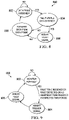
- FIG. 11 a diagram of an illustrative state machine 1100 is shown.
- the state machine 1100 is implemented at least partially by one or more of the monitoring circuit 122 , the monitoring circuit 124 , the monitoring circuit 126 , or the monitoring circuit 128 of the system 100 of FIG. 1 .
- the state machine 1100 will be described with respect to the monitoring circuit 122 , the state machine 1100 is equally applicable to the monitoring circuit 124 , the monitoring circuit 126 , and the monitoring circuit 128 .
- the monitoring circuit implements the state machine 1100 to determine whether a fault exists in the system.
- the state machine 1100 includes a state 1102 , a state 1104 , a state 1106 , and a state 1108 .
- the monitoring circuit forms a data frame.
- forming the data frame comprises reading data from a register and generating the data frame including the data read from the register, as well as one or more additional data elements.
- forming the data frame comprises receiving a data frame and forwarding the received data frame. After forming the data frame, the state machine 1100 transitions to state 1104 .
- the monitoring circuit determines whether a fault is detected.
- the fault is, for example, a fault with a component monitored by the monitoring circuit.
- the component is an energy storage element, such as a battery of a hybrid or electric vehicle (e.g., such as a component of a hybrid or electric vehicle powertrain or power sub-system).
- the state machine 1100 transitions to state 1106 .
- the state machine 1100 transitions to state 1108 .
- the monitoring circuit transmits the data frame.
- the data frame is transmitted to another monitoring circuit that itself implements the state machine 1100 or another state machine substantially similar to the state machine 1100 .
- the data frame is transmitted to a communication bridge, such as the communication bridge 116 of the system 100 . After transmitting the data frame, in at least some examples, the state machine 1100 returns to the state 1102 .
- the monitoring circuit sets a fault status in the data frame.
- setting the fault status comprises performing a logical OR operation between data bit(s) being set and a value of logical 1.
- setting the fault status includes modifying the content of one or more bytes of the data frame (e.g., such as to indicate that a fault exists, indicate a nature of a fault, indicate a location of a fault, etc.). After setting the fault status, the state machine 1100 transitions to the state 1106 .
- FIG. 12 a diagram of an illustrative state machine 1200 is shown.
- the state machine 1200 is implemented at least partially by one or more of the monitoring circuit 122 , the monitoring circuit 124 , the monitoring circuit 126 , or the monitoring circuit 128 of the system 100 of FIG. 1 .
- the state machine 1200 will be described with respect to the monitoring circuit 122 , the state machine 1200 is equally applicable to the monitoring circuit 124 , the monitoring circuit 126 , and the monitoring circuit 128 .
- the monitoring circuit implements the state machine 1200 to determine whether a fault exists in the system.
- the state machine 1200 includes a state 1202 , a state 1204 , and a state 1206 .
- the monitoring circuit monitors to determine whether a fault exists.
- the fault is, for example, a fault with a component monitored by the monitoring circuit.
- the component is an energy storage element, such as a battery of a hybrid or electric vehicle (e.g., such as a component of a hybrid or electric vehicle powertrain or power sub-system).
- a fault exists when the monitoring device detects a fault with a monitored component, when the monitoring device receives a fault tone from another device, or when the monitoring device does not receive a heartbeat tone for a predetermined period of time or within an expected time period.
- the fault tone and/or the heartbeat tone are received, or would be received, by the monitoring device from another monitoring circuit or a communication bridge.
- the state machine 1200 transitions to state 1206 .
- the state machine 1200 transitions to state 1204 .
- the monitoring circuit generates and transmits a fault tone.
- the fault tone in at least some examples, is a signal having another predetermined pattern of pulses.
- the predetermined pattern of pulses is specific to the monitoring circuit generating the fault tone.
- the predetermined pattern of pulses of the fault tone is specific to a type or nature of a fault.
- the predetermined pattern of pulses of the fault tone is specific to a type or nature of a fault.
- the predetermined pattern of pulses is specific to a relative or approximate location of a fault.
- the fault tone is transmitted to another monitoring circuit.
- the fault tone is transmitted to a communication bridge. After generating and transmitting the fault tone, in at least some examples, the state machine 1200 transitions to the state 1202 .
- the monitoring circuit generates and outputs a heartbeat tone.
- the heartbeat tone in at least some examples, is a signal having a predetermined pattern of pulses.
- the heartbeat tone is transmitted to another monitoring circuit.
- the heartbeat tone is transmitted to a communication bridge. After transmitting the heartbeat tone, the state machine 1200 transitions back to the state 1202 .
- the terms “including” and “comprising” are used in an open-ended fashion, and thus should be interpreted to mean “including, but not limited to . . . .”
- the term “couple” is used throughout the specification. The term may cover connections, communications, or signal paths that enable a functional relationship consistent with the description of the present disclosure. For example, if device A generates a signal to control device B to perform an action, in a first example device A is coupled to device B, or in a second example device A is coupled to device B through intervening component C if intervening component C does not substantially alter the functional relationship between device A and device B such that device B is controlled by device A via the control signal generated by device A.
- a device that is “configured to” perform a task or function may be configured (e.g., programmed and/or hardwired) at a time of manufacturing by a manufacturer to perform the function and/or may be configurable (or re-configurable) by a user after manufacturing to perform the function and/or other additional or alternative functions.
- the configuring may be through firmware and/or software programming of the device, through a construction and/or layout of hardware components and interconnections of the device, or a combination thereof.
- a circuit or device that is said to include certain components may instead be configured to couple to those components to form the described circuitry or device.
- a structure described as including one or more semiconductor elements such as transistors), one or more passive elements (such as resistors, capacitors, and/or inductors), and/or one or more sources (such as voltage and/or current sources) may instead include only the semiconductor elements within a single physical device (e.g., a semiconductor die and/or integrated circuit (IC) package) and may be configured to couple to at least some of the passive elements and/or the sources to form the described structure either at a time of manufacture or after a time of manufacture, for example, by an end-user and/or a third-party.
- semiconductor elements such as transistors
- passive elements such as resistors, capacitors, and/or inductors
- sources such as voltage and/or current sources
Landscapes
- Engineering & Computer Science (AREA)
- Theoretical Computer Science (AREA)
- General Engineering & Computer Science (AREA)
- Physics & Mathematics (AREA)
- General Physics & Mathematics (AREA)
- Quality & Reliability (AREA)
- Computer Hardware Design (AREA)
- Debugging And Monitoring (AREA)
Abstract
Description
Claims (15)
Priority Applications (1)
| Application Number | Priority Date | Filing Date | Title |
|---|---|---|---|
| US16/794,067 US11340975B2 (en) | 2019-02-18 | 2020-02-18 | System monitor |
Applications Claiming Priority (3)
| Application Number | Priority Date | Filing Date | Title |
|---|---|---|---|
| US201962807145P | 2019-02-18 | 2019-02-18 | |
| US201962903436P | 2019-09-20 | 2019-09-20 | |
| US16/794,067 US11340975B2 (en) | 2019-02-18 | 2020-02-18 | System monitor |
Publications (2)
| Publication Number | Publication Date |
|---|---|
| US20200264945A1 US20200264945A1 (en) | 2020-08-20 |
| US11340975B2 true US11340975B2 (en) | 2022-05-24 |
Family
ID=72042221
Family Applications (1)
| Application Number | Title | Priority Date | Filing Date |
|---|---|---|---|
| US16/794,067 Active 2040-04-19 US11340975B2 (en) | 2019-02-18 | 2020-02-18 | System monitor |
Country Status (1)
| Country | Link |
|---|---|
| US (1) | US11340975B2 (en) |
Families Citing this family (7)
| Publication number | Priority date | Publication date | Assignee | Title |
|---|---|---|---|---|
| DE112021005135T5 (en) * | 2020-10-01 | 2023-07-13 | Analog Devices, Inc. | Method for monitoring system parameters with low power consumption |
| US11947478B2 (en) * | 2020-12-11 | 2024-04-02 | Sct Ltd. | Methods for identifying target slave address for serial communication interface |
| CN112596501B (en) * | 2020-12-17 | 2022-04-29 | 河南嘉晨智能控制股份有限公司 | A processor, vehicle remote diagnosis system and method |
| CN114714909A (en) * | 2021-01-05 | 2022-07-08 | 广汽埃安新能源汽车有限公司 | Power battery monitoring system and vehicle |
| CN115309689B (en) * | 2022-02-24 | 2026-01-02 | 广州硅芯电子科技有限公司 | A method of using a host to program and control multiple slave devices in a daisy chain. |
| US12519924B2 (en) | 2022-08-31 | 2026-01-06 | Snap Inc. | Multi-perspective augmented reality experience |
| US12466415B2 (en) * | 2023-04-28 | 2025-11-11 | Qualcomm Incorporated | Domain isolation in an automotive automated driving system |
Citations (4)
| Publication number | Priority date | Publication date | Assignee | Title |
|---|---|---|---|---|
| US20090099802A1 (en) * | 2007-10-10 | 2009-04-16 | Texas Instruments Incorporated | Systems, Methods and Circuits for Determining Potential Battery Failure Based on a Rate of Change of Internal Impedance |
| US20130169038A1 (en) * | 2011-12-30 | 2013-07-04 | Allen King | Uninterruptible battery power for electric motor vehicle |
| US20160170824A1 (en) * | 2014-12-16 | 2016-06-16 | Oshri Ben Hamo | Apparatus, method and system to exchange error information in a unified protocol communication |
| US20160261127A1 (en) * | 2014-08-26 | 2016-09-08 | Elite Power Innovations, Llc | Method and system for battery management |
-
2020
- 2020-02-18 US US16/794,067 patent/US11340975B2/en active Active
Patent Citations (4)
| Publication number | Priority date | Publication date | Assignee | Title |
|---|---|---|---|---|
| US20090099802A1 (en) * | 2007-10-10 | 2009-04-16 | Texas Instruments Incorporated | Systems, Methods and Circuits for Determining Potential Battery Failure Based on a Rate of Change of Internal Impedance |
| US20130169038A1 (en) * | 2011-12-30 | 2013-07-04 | Allen King | Uninterruptible battery power for electric motor vehicle |
| US20160261127A1 (en) * | 2014-08-26 | 2016-09-08 | Elite Power Innovations, Llc | Method and system for battery management |
| US20160170824A1 (en) * | 2014-12-16 | 2016-06-16 | Oshri Ben Hamo | Apparatus, method and system to exchange error information in a unified protocol communication |
Also Published As
| Publication number | Publication date |
|---|---|
| US20200264945A1 (en) | 2020-08-20 |
Similar Documents
| Publication | Publication Date | Title |
|---|---|---|
| US11340975B2 (en) | System monitor | |
| JP7527312B2 (en) | PHYSICAL LAYER DEVICE HAVING SLEEP MODE AND PARTIAL NETWORKING SUPPORT, AND ASSOCIATED SYSTEMS, METHODS, AND DEVICES - Patent application | |
| US9043623B2 (en) | Host initiated state control of remote client in communications system | |
| CN211223102U (en) | Bidirectional wake-up circuit of battery management system, battery management system and electric vehicle | |
| US8081643B2 (en) | Relay connection unit | |
| US20080008103A1 (en) | Communication network system and wakeup method for un-wakeup node | |
| KR101967464B1 (en) | Method for preventing battery discharge and electronic control unit using the same | |
| CN103246577A (en) | Watchdog circuits, power ICs, and watchdog monitoring systems | |
| US12512700B2 (en) | Communication system and electronic control device | |
| US20240351520A1 (en) | In-vehicle apparatus, information processing method, and program | |
| JP5260762B2 (en) | Transmission network with optical receiver using two power supply pins and one status pin to reduce power consumption, reduce manufacturing cost and increase transmission efficiency | |
| JP2010245935A (en) | Gateway device, slave device, and network system | |
| US20250123668A1 (en) | Communication system and electronic control device | |
| US8775841B2 (en) | Circuit configuration having a transceiver circuit for a bus system and nodes for a bus system | |
| JP2015154189A (en) | Communication system, gateway device, communication node and communication control method | |
| CN103532724B (en) | A kind of MOST network interface circuit and MOST network state control method | |
| CN115339403A (en) | On-vehicle device diagnosis device, vehicle provided with on-vehicle device diagnosis device, on-vehicle device diagnosis method, and storage medium | |
| CN118418962B (en) | Control method, module, system and vehicle of electronic parking brake | |
| JP4866214B2 (en) | Control unit and in-vehicle multiple communication system | |
| US20240031181A1 (en) | Managing power state at a physical layer | |
| CN114363728B (en) | Electronic device and method for preventing current backflow | |
| CN101938360B (en) | Network interface device and related power saving method | |
| JP5678843B2 (en) | Integrated circuit device | |
| CN120237754A (en) | Power supply system and power supply method of vehicle-mounted power supply | |
| CN119960334A (en) | Power timing control chip and method, and computer readable storage medium |
Legal Events
| Date | Code | Title | Description |
|---|---|---|---|
| FEPP | Fee payment procedure |
Free format text: ENTITY STATUS SET TO UNDISCOUNTED (ORIGINAL EVENT CODE: BIG.); ENTITY STATUS OF PATENT OWNER: LARGE ENTITY |
|
| STPP | Information on status: patent application and granting procedure in general |
Free format text: DOCKETED NEW CASE - READY FOR EXAMINATION |
|
| AS | Assignment |
Owner name: TEXAS INSTRUMENTS INCORPORATED, TEXAS Free format text: ASSIGNMENT OF ASSIGNORS INTEREST;ASSIGNORS:GANGOPADHYAY, INDRANIL;HUI, WAN LAAN JACKIE;SCOTT, KYL WAYNE;AND OTHERS;SIGNING DATES FROM 20200320 TO 20201005;REEL/FRAME:054035/0966 |
|
| STPP | Information on status: patent application and granting procedure in general |
Free format text: NON FINAL ACTION MAILED |
|
| STPP | Information on status: patent application and granting procedure in general |
Free format text: RESPONSE TO NON-FINAL OFFICE ACTION ENTERED AND FORWARDED TO EXAMINER |
|
| STPP | Information on status: patent application and granting procedure in general |
Free format text: FINAL REJECTION MAILED |
|
| STPP | Information on status: patent application and granting procedure in general |
Free format text: NOTICE OF ALLOWANCE MAILED -- APPLICATION RECEIVED IN OFFICE OF PUBLICATIONS |
|
| STPP | Information on status: patent application and granting procedure in general |
Free format text: PUBLICATIONS -- ISSUE FEE PAYMENT VERIFIED |
|
| STCF | Information on status: patent grant |
Free format text: PATENTED CASE |
|
| MAFP | Maintenance fee payment |
Free format text: PAYMENT OF MAINTENANCE FEE, 4TH YEAR, LARGE ENTITY (ORIGINAL EVENT CODE: M1551); ENTITY STATUS OF PATENT OWNER: LARGE ENTITY Year of fee payment: 4 |