US11338917B2 - Ducted fan assembly with a movable leading edge - Google Patents
Ducted fan assembly with a movable leading edge Download PDFInfo
- Publication number
- US11338917B2 US11338917B2 US17/036,942 US202017036942A US11338917B2 US 11338917 B2 US11338917 B2 US 11338917B2 US 202017036942 A US202017036942 A US 202017036942A US 11338917 B2 US11338917 B2 US 11338917B2
- Authority
- US
- United States
- Prior art keywords
- fan assembly
- leading edge
- ducted fan
- mode
- aircraft
- Prior art date
- Legal status (The legal status is an assumption and is not a legal conclusion. Google has not performed a legal analysis and makes no representation as to the accuracy of the status listed.)
- Active, expires
Links
Images


Classifications
-
- F—MECHANICAL ENGINEERING; LIGHTING; HEATING; WEAPONS; BLASTING
- F04—POSITIVE - DISPLACEMENT MACHINES FOR LIQUIDS; PUMPS FOR LIQUIDS OR ELASTIC FLUIDS
- F04D—NON-POSITIVE-DISPLACEMENT PUMPS
- F04D19/00—Axial-flow pumps
-
- B—PERFORMING OPERATIONS; TRANSPORTING
- B64—AIRCRAFT; AVIATION; COSMONAUTICS
- B64C—AEROPLANES; HELICOPTERS
- B64C29/00—Aircraft capable of landing or taking-off vertically, e.g. vertical take-off and landing [VTOL] aircraft
- B64C29/0008—Aircraft capable of landing or taking-off vertically, e.g. vertical take-off and landing [VTOL] aircraft having its flight directional axis horizontal when grounded
- B64C29/0016—Aircraft capable of landing or taking-off vertically, e.g. vertical take-off and landing [VTOL] aircraft having its flight directional axis horizontal when grounded the lift during taking-off being created by free or ducted propellers or by blowers
- B64C29/0033—Aircraft capable of landing or taking-off vertically, e.g. vertical take-off and landing [VTOL] aircraft having its flight directional axis horizontal when grounded the lift during taking-off being created by free or ducted propellers or by blowers the propellers being tiltable relative to the fuselage
-
- F—MECHANICAL ENGINEERING; LIGHTING; HEATING; WEAPONS; BLASTING
- F04—POSITIVE - DISPLACEMENT MACHINES FOR LIQUIDS; PUMPS FOR LIQUIDS OR ELASTIC FLUIDS
- F04D—NON-POSITIVE-DISPLACEMENT PUMPS
- F04D27/00—Control, e.g. regulation, of pumps, pumping installations or pumping systems specially adapted for elastic fluids
-
- F—MECHANICAL ENGINEERING; LIGHTING; HEATING; WEAPONS; BLASTING
- F04—POSITIVE - DISPLACEMENT MACHINES FOR LIQUIDS; PUMPS FOR LIQUIDS OR ELASTIC FLUIDS
- F04D—NON-POSITIVE-DISPLACEMENT PUMPS
- F04D29/00—Details, component parts, or accessories
- F04D29/18—Rotors
- F04D29/181—Axial flow rotors
-
- F—MECHANICAL ENGINEERING; LIGHTING; HEATING; WEAPONS; BLASTING
- F04—POSITIVE - DISPLACEMENT MACHINES FOR LIQUIDS; PUMPS FOR LIQUIDS OR ELASTIC FLUIDS
- F04D—NON-POSITIVE-DISPLACEMENT PUMPS
- F04D29/00—Details, component parts, or accessories
- F04D29/26—Rotors specially for elastic fluids
- F04D29/32—Rotors specially for elastic fluids for axial flow pumps
- F04D29/325—Rotors specially for elastic fluids for axial flow pumps for axial flow fans
- F04D29/326—Rotors specially for elastic fluids for axial flow pumps for axial flow fans comprising a rotating shroud
-
- F—MECHANICAL ENGINEERING; LIGHTING; HEATING; WEAPONS; BLASTING
- F04—POSITIVE - DISPLACEMENT MACHINES FOR LIQUIDS; PUMPS FOR LIQUIDS OR ELASTIC FLUIDS
- F04D—NON-POSITIVE-DISPLACEMENT PUMPS
- F04D29/00—Details, component parts, or accessories
- F04D29/40—Casings; Connections of working fluid
- F04D29/52—Casings; Connections of working fluid for axial pumps
- F04D29/54—Fluid-guiding means, e.g. diffusers
- F04D29/56—Fluid-guiding means, e.g. diffusers adjustable
- F04D29/563—Fluid-guiding means, e.g. diffusers adjustable specially adapted for elastic fluid pumps
Definitions
- the present disclosure relates generally to rotor-driven aircraft and more particularly, but not by way of limitation, to a ducted fan assembly with a movable leading edge.
- Tiltrotor aircraft are configured to fly in helicopter mode for vertical takeoff and landing (VTOL) and in airplane mode for high-speed flight. These aircraft are preferably compact and light-weight vehicles.
- One safety aspect in consideration is the durability of components of the aircraft, such as the rotor ducts.
- aircraft sometimes encounter foreign objects (e.g., birds or debris) that may strike a rotor or a rotor duct.
- components of the aircraft e.g., the rotor duct
- a ducted fan assembly in an embodiment, includes a housing that further includes a rotor.
- the ducted fan assembly also includes a rim that defines an opening surrounding at least a portion of the housing.
- the ducted fan assembly also includes a movable leading edge that is attached to the rim and extends around at least a portion of a perimeter of the ducted fan assembly, where the movable leading edge is adjustable between at least a first position and a second position.
- a method is performed on an aircraft that includes a ducted fan assembly.
- the method includes, during a first mode of operation of the aircraft, adjusting a movable leading edge of the ducted fan assembly to a first position in which the movable leading edge extends outward from a rim of the ducted fan assembly.
- a rotorcraft in an embodiment, includes a plurality of fan assemblies.
- Each fan assembly includes a housing that further includes a rotor.
- Each fan assembly also includes a rim that defines an opening surrounding at least a portion of the housing.
- Each fan assembly also includes a movable leading edge that is attached to the rim and extends around at least a portion of a perimeter of the fan assembly, where the movable leading edge is adjustable between at least a first position and a second position.
- FIG. 1 is a perspective view of an aircraft oriented in a helicopter mode according to aspects of the disclosure
- FIG. 2 is a perspective view of an aircraft oriented in an airplane mode according to aspects of the disclosure
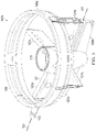
- FIG. 3 is a perspective view of a ducted fan assembly according to aspects of the disclosure.
- FIG. 4 is a sectioned view of a ducted fan assembly according to aspects of the disclosure.
- FIGS. 5A-C illustrate a ducted fan assembly with an adjustable bladder in a first position for helicopter mode
- FIGS. 6A-C illustrate a ducted fan assembly with an adjustable bladder in a second position for airplane mode.
- Rotorcraft 101 is generally configured as a vertical takeoff and landing (VTOL) aircraft, more specifically a tiltrotor, that is operable in an airplane mode associated with forward flight and a helicopter mode associated with vertical takeoff from and landing to a landing zone.
- VTOL vertical takeoff and landing
- Rotorcraft 101 comprises a fuselage 103 comprising a cockpit and/or passenger compartment, wings 105 extending from the fuselage 103 , a pair of ducted fan assemblies 107 a , 107 b carried by, supported by and/or otherwise coupled to fuselage 103 , a pair of ducted fan assemblies 107 c , 107 d carried by, supported by, and/or otherwise coupled to wings 105 .
- Ducted fan assemblies 107 a - 107 d are arranged about fuselage 103 to be generally coplanar when rotorcraft 101 is in helicopter and airplane modes.
- Each ducted fan assembly 107 a , 107 b is supported by a rotatable shaft or spindle 113 extending at least partially through fuselage 103 and coupled to the pair of ducted fan assemblies 107 a , 107 b .
- the pair of ducted fan assemblies 107 a , 107 b may be selectively rotated with respect to fuselage 103 by at least one actuator (e.g. electric, electro-mechanical, magnetic, and/or hydraulic) in order to transition rotorcraft 101 between the airplane and helicopter modes.
- Each ducted fan assembly 107 a - 107 d comprises a duct 108 a - 108 d , respectively, with each duct 108 a - 108 d having a plurality of structural supports and/or struts 110 a - 110 d .
- outer surfaces of the ducts 108 may be shaped to provide optimal and/or preferred flight characteristics in at least one of the airplane mode and the helicopter mode.
- Ducted fan assemblies 107 a , 107 b each include a fan 112 a , 112 b , respectively. It will be appreciated that fans 112 a , 112 b rotate in opposing directions with respect to one another to balance the torque generated by each fan 112 a , 112 b .
- Each fan 112 a , 112 b includes plurality of rotor blades.
- Fans 112 a , 112 b are disposed within their respective duct 108 and are configured to generate thrust when selectively rotated. As illustrated in FIGS. 1 and 2 , each fan 112 a , 112 b comprises five rotor blades. However, in other aspects, each fan 112 a , 112 b may comprise two, three, five, six, seven, eight, and/or more rotor blades.
- Each wing 105 carries a single ducted fan assembly of the pair of ducted fan assemblies 107 c , 107 d .
- the pair of ducted fan assemblies 107 c , 107 d are supported by a rotatable shaft or spindle (e.g., similar to spindle 113 ) that extends at least partially through wings 105 and is coupled to the pair of ducted fan assemblies 107 c , 107 d .
- the pair of ducted fan assemblies 107 c , 107 d may be selectively rotated with respect to fuselage 103 by at least one actuator (e.g. electric, electro-mechanical, magnetic, and/or hydraulic) in order to transition rotorcraft 101 between the airplane and helicopter modes.
- actuator e.g. electric, electro-mechanical, magnetic, and/or hydraulic
- the pair of ducted fan assemblies 107 c , 107 d are structurally similar to the pair of ducted fan assemblies 107 a , 107 b and each includes its own duct 108 c , 108 d , struts 110 c , 110 d , fans 112 c , 112 d .
- the pair of ducted fan assemblies 107 c , 107 d are disposed further outboard of fuselage 103 .
- Rotorcraft 101 is controlled via flight control system 150 .
- Flight control system 150 includes flight control computer 152 that connected to and in communication with propulsion system 154 .
- Propulsion system 154 is controlled by flight control computer 152 and includes components that assist with the flight of rotorcraft 101 .
- Propulsion system 154 may generally include a hybrid electrical system, a hybrid hydraulic system and/or combinations thereof.
- Flight control computer 152 is configured to selectively control the components of propulsion system 154 to operate rotorcraft 101 .
- Flight control system 150 may include flight control input hardware (e.g.
- flight controls configured to receive inputs and/or commands from a pilot to control operation of the rotorcraft 101 and/or a plurality of sensors and/or gauges configured to provide feedback regarding operational characteristics of rotorcraft 101 to the flight control computer 152 .
- flight control computer 152 may be configured to selectively control the operation, orientation, rotation, position, and/or rotational speed of the pairs of ducted fan assemblies 107 a , 107 b and 107 c , 107 d .
- flight control system 150 may comprise fly-by-wire architecture for controlling rotorcraft 101 . Additionally, in some aspects, flight control system 150 may be capable of optionally-piloted operation.
- flight control system 150 may comprise collective pitch control for adjusting the pitch of rotor blades 124 and rotational speed control for individually adjusting a rotational speed of rotor systems 122 of each of the ducted fan assemblies 107 a - 107 d , without the need for cyclic control for controlling operation of rotorcraft 101 .
- FIG. 3 illustrates ducted fan assembly 107 a according to aspects of the disclosure.
- Ducted fan assembly 107 a will be discussed with the understanding that the discussion thereof applies to ducted fan assemblies 107 b - 107 d .
- Ducted fan assembly 107 a is depicted in FIG. 3 without fan 112 a .
- Ducted fan assembly 107 a includes duct 108 a and a central housing 119 that is configured to support and house components such as a rotor, a gearbox, and/or other components to which fan 112 a may be positioned over and attached.
- Ducted fan assembly 107 a further includes a plurality of stators 121 that extend outward from housing 119 .
- ducted fan assembly 107 a includes four stators 121 that extend radially outward from housing 119 . More specifically, ducted fan assembly 107 a has two primary stators that include an inboard primary stator 121 a and an outboard primary stator 121 b . Inboard primary stator 121 a is configured to be coupled to a corresponding spindle, such as spindle 113 . Ducted fan assembly 107 a is rotatable about a spindle axis 123 that is defined by spindle 113 . Ducted fan assembly 107 a includes two secondary stators 121 c .
- Primary inboard and outboard stators 121 a , 121 b respectively are configured to carry a larger proportion of the load of ducted fan assembly 107 a back to fuselage 103 than are secondary stators 121 c .
- Inboard primary stator 121 a and outboard primary stator 121 b are longitudinally aligned relative to each other on opposed sides of housing 119 and secondary stators 121 c are longitudinally aligned relative to each other on opposed sides of housing 119 and aligned perpendicularly to inboard primary stator 121 a and outboard primary stator 121 b .
- stators 121 are equally spaced about housing 119 .
- ducted fan assembly 107 may be alternatively configured with more or fewer stators 121 .
- ducted fan assembly 107 a may be alternatively configured with different spacing of stators 121 about housing 119 .
- Ducted fan assembly 107 a further includes an inboard control vane 125 a and an outboard control vane 125 b , which are pivotally attached to inboard primary stator 121 a and outboard primary stator 121 b , respectively.
- Inboard control vane 125 a and outboard control vane 125 b are pivotable about a vane axis 127 that extends parallel to spindle axis 123 .
- inboard control vane 125 a and outboard control vane 125 b are configured to rotate together to facilitate yaw control, changes of direction, turning, etc. during flight of rotorcraft 101 .
- inboard control vane 125 a and outboard control vane 125 b may alternatively be configured to rotate independently from one another.
- ducted fan assembly 107 a is not limited to the illustrated configuration of inboard control vane 125 a and outboard control vane 125 b .
- ducted fan assembly 107 a may alternatively be configured with more or fewer control vanes, such as a single control vane that defines a continuous control surface.
- Ducted fan assembly 107 a includes a movable leading edge 129 that forms an outer covering of ducted fan assembly 107 a , and that defines an opening that extends through ducted fan assembly 107 a .
- housing 119 is located primarily aft of the opening.
- An outer surface of movable leading edge 129 can include, for example, one or more sections of skin.
- Movable leading edge 129 is configured to change shape, or adjust between various positions, to alter the flow path of air around duct 108 a .
- movable leading edge 129 can adjust between a first position for helicopter mode and a second position for airplane mode.
- first position for helicopter mode movable leading edge 129 can extend to form a lip, or bulge, that maximizes the amount of lift produced by ducted fan assembly 107 a .
- second position for airplane mode movable leading edge 129 can be retracted relative to the first position so as to reduce drag for more efficient aerodynamics.
- movable leading edge 129 can be, for example, a rigid structure that is mechanically actuated to extend and retract.
- movable leading edge 129 can be formed from a multiple-chamber bladder that extends and retracts through changes in air pressure.
- An example structure of movable leading edge 129 will be discussed in more detail relative to FIGS. 4, 5A -C and 6 A-C.
- FIG. 4 is a sectioned view of ducted fan assembly 107 a according to aspects of the disclosure.
- Ducted fan assembly 107 a includes a rim 128 that extends around the perimeter of duct 108 a and is supported by the plurality of stators 121 and the control vanes 125 .
- Rim 128 provides structure and support for ducted fan assembly 107 a .
- rim 128 defines an opening surrounding at least a portion of central housing 119 .
- rim 128 sits on, or is attached to, rim 128 to form movable leading edge 129 .
- rim 128 includes a frame 132 that in cross-section forms a hat-like shape. Frame 132 reinforces rim 128 and provides additional structure to which adjustable bladder 130 may be secured.
- Rim 128 is positioned within duct 108 a to be adjacent to fan 112 a .
- rim 128 is made from metals or composites that are more rigid than adjustable bladder 130 , such that the rim 128 has greater rigidity than adjustable bladder 130 .
- a space between the tips of fan 112 a and duct 108 a is, for example, less than or equal to 0.25 inches.
- Adjustable bladder 130 is formed from a pliable material that can deform in the event a foreign object impacts adjustable bladder 130 during flight. Allowing adjustable bladder 130 to deform attenuates the energy of the strike to minimize or eliminate damage to duct 108 a . Adjustable bladder 130 is rigid enough to provide a desired aerodynamic shape to improve the performance of duct 108 a (i.e., maintains shape for the efficient flow of air over duct 108 a to improve the amount of thrust generated by ducted fan assembly 107 a ), but is also pliable enough to absorb and withstand impacts from foreign objects.
- adjustable bladder 130 may be made from various polymers. In some aspects, the polymer is a rubber material and may be reinforced with fibers (e.g., polymers and the like).
- Adjustable bladder 130 includes multiple chambers configured to be filled with a gas.
- each chamber of adjustable bladder 130 is separately filled with a gas (e.g., nitrogen as nitrogen is less sensitive to changes in temperature) and sealed.
- a first chamber of adjustable bladder 130 can remain at a constant pressure while a second chamber of adjustable bladder 130 can have a variable pressure. The pressure within the second chamber can be controlled, or varied, so as to cause the adjustable bladder 130 , and the movable leadable edge 129 formed thereby, to adjust between the first position for helicopter mode and the second position for airplane mode.
- the second chamber in the first position for helicopter mode, has its pressure increased so as to cause adjustable bladder 130 to extend outward from rim 128 to form a lip or bulge that maximizes the amount of lift produced by ducted fan assembly 107 a .
- the second chamber in the second position for airplane mode, can have its pressure decreased (e.g., complete deflation in some embodiments) so as to cause adjustable bladder 130 to retract inward, toward rim 128 , to form a more aerodynamic shape suitable for airplane mode.
- adjustable bladder 130 is in the second position for airplane mode.
- adjustable bladder 130 is described as having two chambers and configurability to adjust between two positions, in various embodiments, adjustable bladder 130 can have any number of chambers and configurability to adjust between or among any number of positions.
- adjustable bladder 130 The rigidity of adjustable bladder 130 is determined in part by the material it is made from and in part by the pressure provided by the gas with which its chambers are filled.
- adjustable bladder 130 may include a feature 138 , such as a blow-off valve, a weakened section, and the like, to bleed off pressure that results from a foreign object impacting adjustable bladder 130 during flight. In the event of a failure of adjustable bladder 130 or as a part of maintenance, adjustable bladder 130 may be removed from rim 128 for inspection, repair, or replacement.
- adjustable bladder 130 offers improved performance regarding impacts by foreign objects. For example, compared to metals and composites, adjustable bladder 130 can more easily retain its shape after an impact event. Retaining shape after an impact event can prevent the loss in performance that occurs when a metal or composite duct is deformed or destroyed by an impact event. Adjustable bladder 130 also provides weight savings compared to conventional duct designs. A further benefit is the ease and low cost with which adjustable bladder 130 can be manufactured.
- FIGS. 5A-C illustrate ducted fan assembly 107 a with adjustable bladder 130 in the first position for helicopter mode. More particularly, FIG. 5A is a sectioned view in which adjustable bladder 130 is shown to have two chambers, namely, a first chamber 131 and a second chamber 133 .
- the first chamber 131 has approximately the same pressure in both the first position for helicopter mode and the second position for airplane mode.
- the second chamber 133 has been inflated, or had its pressure increased, such that movable leading edge 129 extends outward to form a lip or bulge. As described previously, the lip or bulge of the movable leading edge 129 serves to maximize the amount of lift produced by ducted fan assembly 107 a .
- FIG. 5A is a sectioned view in which adjustable bladder 130 is shown to have two chambers, namely, a first chamber 131 and a second chamber 133 .
- the first chamber 131 has approximately the same pressure in both the first position for helicopter mode and the second position for airplane mode.
- FIG. 5B is a zoomed-in view of the sectioned view of FIG. 5A .
- FIG. 5C is a perspective view of adjustable bladder 130 in the first position for helicopter mode and illustrates the lip or bulge of the movable leading edge 129 extending around the entire perimeter of ducted fan assembly 107 a.
- FIGS. 6A-C illustrate ducted fan assembly 107 a with adjustable bladder 130 in the second position for airplane mode. More particularly, FIG. 6A is a sectioned view showing the first chamber 131 at approximately the same pressure described relative FIGS. 5A-C . In the illustrated embodiment, the second chamber 133 has been deflated, or had its pressure decreased, such that movable leading edge 129 retracts inward and the lip or bulge described relative to FIGS. 5A-C is no longer visible. In that way, the adjustable bladder 130 has retracted to form a more aerodynamic shape suitable for airplane mode. FIG. 6B is a zoomed-in view of the sectioned view of FIG. 6A . FIG. 6C is a perspective view of adjustable bladder 130 in the second position for airplane mode.
- acts, events, or functions of any of the algorithms, methods, or processes described herein can be performed in a different sequence, can be added, merged, or left out altogether (e.g., not all described acts or events are necessary for the practice of the algorithms, methods, or processes).
- acts or events can be performed concurrently, e.g., through multi-threaded processing, interrupt processing, or multiple processors or processor cores or on other parallel architectures, rather than sequentially.
- certain computer-implemented tasks are described as being performed by a particular entity, other aspects are possible in which these tasks are performed by a different entity.
- substantially is defined as largely but not necessarily wholly what is specified (and includes what is specified; e.g., substantially 90 degrees includes 90 degrees and substantially parallel includes parallel), as understood by a person of ordinary skill in the art.
- the terms “substantially,” “approximately,” “generally,” “generally in the range of,” and “about” may be substituted with “within [a percentage] of” what is specified, as understood by a person of ordinary skill in the art. For example, within 1%, 2%, 3%, 5%, and 10% of what is specified herein.
Abstract
Description
Claims (18)
Priority Applications (1)
| Application Number | Priority Date | Filing Date | Title |
|---|---|---|---|
| US17/036,942 US11338917B2 (en) | 2020-09-29 | 2020-09-29 | Ducted fan assembly with a movable leading edge |
Applications Claiming Priority (1)
| Application Number | Priority Date | Filing Date | Title |
|---|---|---|---|
| US17/036,942 US11338917B2 (en) | 2020-09-29 | 2020-09-29 | Ducted fan assembly with a movable leading edge |
Publications (2)
| Publication Number | Publication Date |
|---|---|
| US20220097839A1 US20220097839A1 (en) | 2022-03-31 |
| US11338917B2 true US11338917B2 (en) | 2022-05-24 |
Family
ID=80823370
Family Applications (1)
| Application Number | Title | Priority Date | Filing Date |
|---|---|---|---|
| US17/036,942 Active 2040-10-29 US11338917B2 (en) | 2020-09-29 | 2020-09-29 | Ducted fan assembly with a movable leading edge |
Country Status (1)
| Country | Link |
|---|---|
| US (1) | US11338917B2 (en) |
Cited By (1)
| Publication number | Priority date | Publication date | Assignee | Title |
|---|---|---|---|---|
| US20210371093A1 (en) * | 2018-03-31 | 2021-12-02 | Dr. Nakamats Innovation Institute | Aerial vehicle such as high speed drone |
Citations (14)
| Publication number | Priority date | Publication date | Assignee | Title |
|---|---|---|---|---|
| US3054578A (en) * | 1957-10-08 | 1962-09-18 | Cie De Rech S Et D Etudes Aero | Annular aircraft with elastic collector ring rim |
| US3083934A (en) | 1961-10-12 | 1963-04-02 | Edward G Vanderlip | Rotary wing aircraft |
| US3285003A (en) | 1964-02-01 | 1966-11-15 | Dunlop Rubber Co | Inflatable structure |
| US3494380A (en) | 1965-08-10 | 1970-02-10 | Dunlop Rubber Co | Inflatable structures |
| US3524611A (en) | 1968-07-22 | 1970-08-18 | Kurt Frank | Controllable air duct for vertical and short take-off and landing type of air vehicle |
| US4843992A (en) | 1987-07-02 | 1989-07-04 | Sarkis S. Babikian | Air tube protected by belts |
| US20110147533A1 (en) * | 2009-12-21 | 2011-06-23 | Honeywell International Inc. | Morphing ducted fan for vertical take-off and landing vehicle |
| US9297333B2 (en) * | 2014-08-26 | 2016-03-29 | The Boeing Company | Variable geometry inlet for a ducted fan and method of assembling same |
| US20170341725A1 (en) * | 2016-05-29 | 2017-11-30 | Edward Francis Skahan | Motor-wing Gimbal Aircraft, Methods, and Applications |
| US9975631B1 (en) * | 2017-11-01 | 2018-05-22 | Kitty Hawk Corporation | Tiltwing multicopter with foldable and non-foldable propellers |
| US20180208305A1 (en) * | 2016-10-31 | 2018-07-26 | Bell Helicopter Textron Inc. | Vertical Takeoff and Landing (VTOL) Aircraft |
| US20190283888A1 (en) | 2018-03-13 | 2019-09-19 | U. S. Aeronautics, Inc. | Efficient low-noise aircraft propulsion system |
| US10641290B1 (en) * | 2016-09-20 | 2020-05-05 | Piasecki Aircraft Corporation | Ducted fan having aerodynamic features |
| US20200354051A1 (en) * | 2019-04-10 | 2020-11-12 | Safran | Propulsion system for an aircraft |
-
2020
- 2020-09-29 US US17/036,942 patent/US11338917B2/en active Active
Patent Citations (14)
| Publication number | Priority date | Publication date | Assignee | Title |
|---|---|---|---|---|
| US3054578A (en) * | 1957-10-08 | 1962-09-18 | Cie De Rech S Et D Etudes Aero | Annular aircraft with elastic collector ring rim |
| US3083934A (en) | 1961-10-12 | 1963-04-02 | Edward G Vanderlip | Rotary wing aircraft |
| US3285003A (en) | 1964-02-01 | 1966-11-15 | Dunlop Rubber Co | Inflatable structure |
| US3494380A (en) | 1965-08-10 | 1970-02-10 | Dunlop Rubber Co | Inflatable structures |
| US3524611A (en) | 1968-07-22 | 1970-08-18 | Kurt Frank | Controllable air duct for vertical and short take-off and landing type of air vehicle |
| US4843992A (en) | 1987-07-02 | 1989-07-04 | Sarkis S. Babikian | Air tube protected by belts |
| US20110147533A1 (en) * | 2009-12-21 | 2011-06-23 | Honeywell International Inc. | Morphing ducted fan for vertical take-off and landing vehicle |
| US9297333B2 (en) * | 2014-08-26 | 2016-03-29 | The Boeing Company | Variable geometry inlet for a ducted fan and method of assembling same |
| US20170341725A1 (en) * | 2016-05-29 | 2017-11-30 | Edward Francis Skahan | Motor-wing Gimbal Aircraft, Methods, and Applications |
| US10641290B1 (en) * | 2016-09-20 | 2020-05-05 | Piasecki Aircraft Corporation | Ducted fan having aerodynamic features |
| US20180208305A1 (en) * | 2016-10-31 | 2018-07-26 | Bell Helicopter Textron Inc. | Vertical Takeoff and Landing (VTOL) Aircraft |
| US9975631B1 (en) * | 2017-11-01 | 2018-05-22 | Kitty Hawk Corporation | Tiltwing multicopter with foldable and non-foldable propellers |
| US20190283888A1 (en) | 2018-03-13 | 2019-09-19 | U. S. Aeronautics, Inc. | Efficient low-noise aircraft propulsion system |
| US20200354051A1 (en) * | 2019-04-10 | 2020-11-12 | Safran | Propulsion system for an aircraft |
Non-Patent Citations (3)
| Title |
|---|
| Amante, William Anthony, et al.; "Ducted Fan Assembly for an Aircraft"; U.S. Appl. No. 17/036,798; filed Sep. 29, 2020; 34 pages. |
| Carr, Timothy Brian, et al.; "Ducted Fan Assembly With Blade in Leading Edge"; U.S. Appl. No. 17/037,082; filed Sep. 29, 2020; 38 pages. |
| Carr, Timothy Brian, et al.; "Ducted Fan Assembly With Material-Filled Cavity in Leading Edge"; U.S. Appl. No. 17/037,190; filed Sep. 29, 2020; 38 pages. |
Cited By (1)
| Publication number | Priority date | Publication date | Assignee | Title |
|---|---|---|---|---|
| US20210371093A1 (en) * | 2018-03-31 | 2021-12-02 | Dr. Nakamats Innovation Institute | Aerial vehicle such as high speed drone |
Also Published As
| Publication number | Publication date |
|---|---|
| US20220097839A1 (en) | 2022-03-31 |
Similar Documents
| Publication | Publication Date | Title |
|---|---|---|
| US20220099110A1 (en) | Ducted fan assembly with material-filled cavity in leading edge | |
| CN110035954B (en) | Ventilated rotor mounting boom for private aircraft | |
| JP5421503B2 (en) | Private aircraft | |
| AU659787B2 (en) | Aircraft with a ducted fan in a circular wing | |
| JP5676824B2 (en) | Private aircraft | |
| US10710712B2 (en) | Rotor blade afterbody | |
| CN109665094B (en) | Multi-rotor aircraft with fuselage and at least one wing | |
| US20110174920A1 (en) | Flight control system especially suited for vtol vehicles | |
| JP2003512253A (en) | Airplane and airplane control method | |
| EP3919379B1 (en) | Flight efficiency improving system for compound helicopter | |
| US11338917B2 (en) | Ducted fan assembly with a movable leading edge | |
| US11634216B2 (en) | Ducted fan assembly for an aircraft | |
| US11655021B2 (en) | Rotary wing aircraft with an asymmetrical rear section | |
| US9004394B2 (en) | Mission-adaptive rotor blade with circulation control | |
| US9637229B2 (en) | Mission-adaptive rotor blade with circulation control | |
| US11479338B2 (en) | Ducted fan assembly with blade in leading edge | |
| US20220258858A1 (en) | Rotary wing aircraft with a shrouded tail propeller | |
| CN114954899A (en) | Wing assembly for an aircraft | |
| Cheeseman | Circulation control and its application to stopped rotor aircraft | |
| US11697493B2 (en) | Rotary wing aircraft with a shrouded tail propeller | |
| EP3722208B1 (en) | Powered high-lift system for short take-off and landing (stol) air vehicles | |
| RU2789464C1 (en) | Axisymmetric aircraft | |
| US20220185466A1 (en) | Rotary wing aircraft with an asymmetrical front section | |
| CN116374157A (en) | Aeronautical drive, aircraft and method for operating aeronautical drive | |
| AU2011282250B2 (en) | Personal aircraft |
Legal Events
| Date | Code | Title | Description |
|---|---|---|---|
| AS | Assignment |
Owner name: BELL TEXTRON INC., TEXAS Free format text: ASSIGNMENT OF ASSIGNORS INTEREST;ASSIGNORS:AMANTE, WILLIAM ANTHONY;CARR, TIMOTHY BRIAN;REEL/FRAME:053924/0048 Effective date: 20200924 |
|
| FEPP | Fee payment procedure |
Free format text: ENTITY STATUS SET TO UNDISCOUNTED (ORIGINAL EVENT CODE: BIG.); ENTITY STATUS OF PATENT OWNER: LARGE ENTITY |
|
| AS | Assignment |
Owner name: TEXTRON INNOVATIONS INC., RHODE ISLAND Free format text: ASSIGNMENT OF ASSIGNORS INTEREST;ASSIGNOR:BELL TEXTRON RHODE ISLAND INC.;REEL/FRAME:055603/0134 Effective date: 20210101 Owner name: BELL TEXTRON RHODE ISLAND INC., RHODE ISLAND Free format text: ASSIGNMENT OF ASSIGNORS INTEREST;ASSIGNOR:BELL TEXTRON INC.;REEL/FRAME:055602/0698 Effective date: 20210101 |
|
| STPP | Information on status: patent application and granting procedure in general |
Free format text: RESPONSE TO NON-FINAL OFFICE ACTION ENTERED AND FORWARDED TO EXAMINER |
|
| STPP | Information on status: patent application and granting procedure in general |
Free format text: NOTICE OF ALLOWANCE MAILED -- APPLICATION RECEIVED IN OFFICE OF PUBLICATIONS |
|
| STPP | Information on status: patent application and granting procedure in general |
Free format text: PUBLICATIONS -- ISSUE FEE PAYMENT VERIFIED |
|
| STCF | Information on status: patent grant |
Free format text: PATENTED CASE |