US11326759B2 - Lamp for vehicle having a movable mirror and a light adjustment unit - Google Patents
Lamp for vehicle having a movable mirror and a light adjustment unit Download PDFInfo
- Publication number
- US11326759B2 US11326759B2 US17/071,517 US202017071517A US11326759B2 US 11326759 B2 US11326759 B2 US 11326759B2 US 202017071517 A US202017071517 A US 202017071517A US 11326759 B2 US11326759 B2 US 11326759B2
- Authority
- US
- United States
- Prior art keywords
- light
- lens
- lamp
- unit
- present disclosure
- Prior art date
- Legal status (The legal status is an assumption and is not a legal conclusion. Google has not performed a legal analysis and makes no representation as to the accuracy of the status listed.)
- Active
Links
Images


Classifications
-
- F—MECHANICAL ENGINEERING; LIGHTING; HEATING; WEAPONS; BLASTING
- F21—LIGHTING
- F21S—NON-PORTABLE LIGHTING DEVICES; SYSTEMS THEREOF; VEHICLE LIGHTING DEVICES SPECIALLY ADAPTED FOR VEHICLE EXTERIORS
- F21S41/00—Illuminating devices specially adapted for vehicle exteriors, e.g. headlamps
- F21S41/20—Illuminating devices specially adapted for vehicle exteriors, e.g. headlamps characterised by refractors, transparent cover plates, light guides or filters
-
- F—MECHANICAL ENGINEERING; LIGHTING; HEATING; WEAPONS; BLASTING
- F21—LIGHTING
- F21S—NON-PORTABLE LIGHTING DEVICES; SYSTEMS THEREOF; VEHICLE LIGHTING DEVICES SPECIALLY ADAPTED FOR VEHICLE EXTERIORS
- F21S41/00—Illuminating devices specially adapted for vehicle exteriors, e.g. headlamps
- F21S41/60—Illuminating devices specially adapted for vehicle exteriors, e.g. headlamps characterised by a variable light distribution
- F21S41/63—Illuminating devices specially adapted for vehicle exteriors, e.g. headlamps characterised by a variable light distribution by acting on refractors, filters or transparent cover plates
- F21S41/635—Illuminating devices specially adapted for vehicle exteriors, e.g. headlamps characterised by a variable light distribution by acting on refractors, filters or transparent cover plates by moving refractors, filters or transparent cover plates
-
- F—MECHANICAL ENGINEERING; LIGHTING; HEATING; WEAPONS; BLASTING
- F21—LIGHTING
- F21S—NON-PORTABLE LIGHTING DEVICES; SYSTEMS THEREOF; VEHICLE LIGHTING DEVICES SPECIALLY ADAPTED FOR VEHICLE EXTERIORS
- F21S41/00—Illuminating devices specially adapted for vehicle exteriors, e.g. headlamps
- F21S41/60—Illuminating devices specially adapted for vehicle exteriors, e.g. headlamps characterised by a variable light distribution
- F21S41/67—Illuminating devices specially adapted for vehicle exteriors, e.g. headlamps characterised by a variable light distribution by acting on reflectors
- F21S41/675—Illuminating devices specially adapted for vehicle exteriors, e.g. headlamps characterised by a variable light distribution by acting on reflectors by moving reflectors
-
- F—MECHANICAL ENGINEERING; LIGHTING; HEATING; WEAPONS; BLASTING
- F21—LIGHTING
- F21S—NON-PORTABLE LIGHTING DEVICES; SYSTEMS THEREOF; VEHICLE LIGHTING DEVICES SPECIALLY ADAPTED FOR VEHICLE EXTERIORS
- F21S43/00—Signalling devices specially adapted for vehicle exteriors, e.g. brake lamps, direction indicator lights or reversing lights
- F21S43/30—Signalling devices specially adapted for vehicle exteriors, e.g. brake lamps, direction indicator lights or reversing lights characterised by reflectors
- F21S43/31—Optical layout thereof
-
- B—PERFORMING OPERATIONS; TRANSPORTING
- B60—VEHICLES IN GENERAL
- B60Q—ARRANGEMENT OF SIGNALLING OR LIGHTING DEVICES, THE MOUNTING OR SUPPORTING THEREOF OR CIRCUITS THEREFOR, FOR VEHICLES IN GENERAL
- B60Q1/00—Arrangement of optical signalling or lighting devices, the mounting or supporting thereof or circuits therefor
- B60Q1/0029—Spatial arrangement
-
- B—PERFORMING OPERATIONS; TRANSPORTING
- B60—VEHICLES IN GENERAL
- B60Q—ARRANGEMENT OF SIGNALLING OR LIGHTING DEVICES, THE MOUNTING OR SUPPORTING THEREOF OR CIRCUITS THEREFOR, FOR VEHICLES IN GENERAL
- B60Q1/00—Arrangement of optical signalling or lighting devices, the mounting or supporting thereof or circuits therefor
- B60Q1/26—Arrangement of optical signalling or lighting devices, the mounting or supporting thereof or circuits therefor the devices being primarily intended to indicate the vehicle, or parts thereof, or to give signals, to other traffic
-
- F—MECHANICAL ENGINEERING; LIGHTING; HEATING; WEAPONS; BLASTING
- F21—LIGHTING
- F21S—NON-PORTABLE LIGHTING DEVICES; SYSTEMS THEREOF; VEHICLE LIGHTING DEVICES SPECIALLY ADAPTED FOR VEHICLE EXTERIORS
- F21S10/00—Lighting devices or systems producing a varying lighting effect
- F21S10/02—Lighting devices or systems producing a varying lighting effect changing colors
- F21S10/023—Lighting devices or systems producing a varying lighting effect changing colors by selectively switching fixed light sources
-
- F—MECHANICAL ENGINEERING; LIGHTING; HEATING; WEAPONS; BLASTING
- F21—LIGHTING
- F21S—NON-PORTABLE LIGHTING DEVICES; SYSTEMS THEREOF; VEHICLE LIGHTING DEVICES SPECIALLY ADAPTED FOR VEHICLE EXTERIORS
- F21S41/00—Illuminating devices specially adapted for vehicle exteriors, e.g. headlamps
- F21S41/10—Illuminating devices specially adapted for vehicle exteriors, e.g. headlamps characterised by the light source
- F21S41/12—Illuminating devices specially adapted for vehicle exteriors, e.g. headlamps characterised by the light source characterised by the type of emitted light
- F21S41/125—Coloured light
-
- F—MECHANICAL ENGINEERING; LIGHTING; HEATING; WEAPONS; BLASTING
- F21—LIGHTING
- F21S—NON-PORTABLE LIGHTING DEVICES; SYSTEMS THEREOF; VEHICLE LIGHTING DEVICES SPECIALLY ADAPTED FOR VEHICLE EXTERIORS
- F21S41/00—Illuminating devices specially adapted for vehicle exteriors, e.g. headlamps
- F21S41/20—Illuminating devices specially adapted for vehicle exteriors, e.g. headlamps characterised by refractors, transparent cover plates, light guides or filters
- F21S41/25—Projection lenses
-
- F—MECHANICAL ENGINEERING; LIGHTING; HEATING; WEAPONS; BLASTING
- F21—LIGHTING
- F21S—NON-PORTABLE LIGHTING DEVICES; SYSTEMS THEREOF; VEHICLE LIGHTING DEVICES SPECIALLY ADAPTED FOR VEHICLE EXTERIORS
- F21S41/00—Illuminating devices specially adapted for vehicle exteriors, e.g. headlamps
- F21S41/30—Illuminating devices specially adapted for vehicle exteriors, e.g. headlamps characterised by reflectors
-
- F—MECHANICAL ENGINEERING; LIGHTING; HEATING; WEAPONS; BLASTING
- F21—LIGHTING
- F21S—NON-PORTABLE LIGHTING DEVICES; SYSTEMS THEREOF; VEHICLE LIGHTING DEVICES SPECIALLY ADAPTED FOR VEHICLE EXTERIORS
- F21S41/00—Illuminating devices specially adapted for vehicle exteriors, e.g. headlamps
- F21S41/60—Illuminating devices specially adapted for vehicle exteriors, e.g. headlamps characterised by a variable light distribution
- F21S41/67—Illuminating devices specially adapted for vehicle exteriors, e.g. headlamps characterised by a variable light distribution by acting on reflectors
-
- F—MECHANICAL ENGINEERING; LIGHTING; HEATING; WEAPONS; BLASTING
- F21—LIGHTING
- F21S—NON-PORTABLE LIGHTING DEVICES; SYSTEMS THEREOF; VEHICLE LIGHTING DEVICES SPECIALLY ADAPTED FOR VEHICLE EXTERIORS
- F21S43/00—Signalling devices specially adapted for vehicle exteriors, e.g. brake lamps, direction indicator lights or reversing lights
- F21S43/20—Signalling devices specially adapted for vehicle exteriors, e.g. brake lamps, direction indicator lights or reversing lights characterised by refractors, transparent cover plates, light guides or filters
- F21S43/26—Refractors, transparent cover plates, light guides or filters not provided in groups F21S43/235 - F21S43/255
-
- F—MECHANICAL ENGINEERING; LIGHTING; HEATING; WEAPONS; BLASTING
- F21—LIGHTING
- F21S—NON-PORTABLE LIGHTING DEVICES; SYSTEMS THEREOF; VEHICLE LIGHTING DEVICES SPECIALLY ADAPTED FOR VEHICLE EXTERIORS
- F21S43/00—Signalling devices specially adapted for vehicle exteriors, e.g. brake lamps, direction indicator lights or reversing lights
- F21S43/40—Signalling devices specially adapted for vehicle exteriors, e.g. brake lamps, direction indicator lights or reversing lights characterised by the combination of reflectors and refractors
-
- F—MECHANICAL ENGINEERING; LIGHTING; HEATING; WEAPONS; BLASTING
- F21—LIGHTING
- F21V—FUNCTIONAL FEATURES OR DETAILS OF LIGHTING DEVICES OR SYSTEMS THEREOF; STRUCTURAL COMBINATIONS OF LIGHTING DEVICES WITH OTHER ARTICLES, NOT OTHERWISE PROVIDED FOR
- F21V13/00—Producing particular characteristics or distribution of the light emitted by means of a combination of elements specified in two or more of main groups F21V1/00 - F21V11/00
- F21V13/02—Combinations of only two kinds of elements
- F21V13/04—Combinations of only two kinds of elements the elements being reflectors and refractors
- F21V13/06—Combinations of only two kinds of elements the elements being reflectors and refractors a reflector being rotatable
-
- F—MECHANICAL ENGINEERING; LIGHTING; HEATING; WEAPONS; BLASTING
- F21—LIGHTING
- F21V—FUNCTIONAL FEATURES OR DETAILS OF LIGHTING DEVICES OR SYSTEMS THEREOF; STRUCTURAL COMBINATIONS OF LIGHTING DEVICES WITH OTHER ARTICLES, NOT OTHERWISE PROVIDED FOR
- F21V5/00—Refractors for light sources
- F21V5/02—Refractors for light sources of prismatic shape
-
- F—MECHANICAL ENGINEERING; LIGHTING; HEATING; WEAPONS; BLASTING
- F21—LIGHTING
- F21V—FUNCTIONAL FEATURES OR DETAILS OF LIGHTING DEVICES OR SYSTEMS THEREOF; STRUCTURAL COMBINATIONS OF LIGHTING DEVICES WITH OTHER ARTICLES, NOT OTHERWISE PROVIDED FOR
- F21V5/00—Refractors for light sources
- F21V5/04—Refractors for light sources of lens shape
-
- B—PERFORMING OPERATIONS; TRANSPORTING
- B60—VEHICLES IN GENERAL
- B60Q—ARRANGEMENT OF SIGNALLING OR LIGHTING DEVICES, THE MOUNTING OR SUPPORTING THEREOF OR CIRCUITS THEREFOR, FOR VEHICLES IN GENERAL
- B60Q2300/00—Indexing codes for automatically adjustable headlamps or automatically dimmable headlamps
- B60Q2300/30—Indexing codes relating to the vehicle environment
- B60Q2300/32—Road surface or travel path
-
- B—PERFORMING OPERATIONS; TRANSPORTING
- B60—VEHICLES IN GENERAL
- B60Q—ARRANGEMENT OF SIGNALLING OR LIGHTING DEVICES, THE MOUNTING OR SUPPORTING THEREOF OR CIRCUITS THEREFOR, FOR VEHICLES IN GENERAL
- B60Q2300/00—Indexing codes for automatically adjustable headlamps or automatically dimmable headlamps
- B60Q2300/40—Indexing codes relating to other road users or special conditions
- B60Q2300/45—Special conditions, e.g. pedestrians, road signs or potential dangers
-
- F—MECHANICAL ENGINEERING; LIGHTING; HEATING; WEAPONS; BLASTING
- F21—LIGHTING
- F21W—INDEXING SCHEME ASSOCIATED WITH SUBCLASSES F21K, F21L, F21S and F21V, RELATING TO USES OR APPLICATIONS OF LIGHTING DEVICES OR SYSTEMS
- F21W2103/00—Exterior vehicle lighting devices for signalling purposes
- F21W2103/60—Projection of signs from lighting devices, e.g. symbols or information being projected onto the road
-
- F—MECHANICAL ENGINEERING; LIGHTING; HEATING; WEAPONS; BLASTING
- F21—LIGHTING
- F21W—INDEXING SCHEME ASSOCIATED WITH SUBCLASSES F21K, F21L, F21S and F21V, RELATING TO USES OR APPLICATIONS OF LIGHTING DEVICES OR SYSTEMS
- F21W2107/00—Use or application of lighting devices on or in particular types of vehicles
- F21W2107/10—Use or application of lighting devices on or in particular types of vehicles for land vehicles
Definitions
- the present disclosure relates to a lamp for a vehicle. More specifically, it relates to a lamp for a vehicle that allows an image for information delivery to be formed on a road surface around the vehicle.
- a vehicle is equipped with various types of vehicle lamps having a function of securing a field of view and confirming an object in the vicinity of the vehicle in low light conditions (e.g. nighttime driving), and a signaling function for notifying other vehicle or road users of a running state of the vehicle.
- low light conditions e.g. nighttime driving
- signaling function for notifying other vehicle or road users of a running state of the vehicle.
- head lamps or fog lamps are intended to secure a field of view
- daytime running lamps, position lamps, turn signal lamps, tail lamps, or brake lamps are intended for signaling function.
- installation standards and specifications of such vehicle lamps are stipulated by regulations to allow each function to be fully utilized.
- aspects of the present disclosure provide a lamp for a vehicle that may improve communication with the vehicle by forming an image for information delivery on a road surface around the vehicle. Aspects of the present disclosure also provide a lamp for a vehicle that enables formation of a clear image even if a position where the image is formed on a road surface around the vehicle changes.
- aspects of the present disclosure are not restricted to those set forth herein. The above and other aspects of the present disclosure will become more apparent to one of ordinary skill in the art to which the present disclosure pertains by referencing the detailed description of the present disclosure given below.
- a lamp for a vehicle may include a light source unit for generating a first light; a light adjustment unit for adjusting a first light concentration for the first light to generate a second light having a second light concentration that is different from the first light concentration; and a movable mirror unit for reflecting the second light to form an image of a predetermined shape on a road surface.
- a position where the image is formed on the road surface may be changed depending on a position of the movable mirror unit.
- the light source unit may comprise a plurality of light sources; and an optical unit for synthesizing light generated from the plurality of light sources to generate the first light. At least some of the plurality of light sources may generate light of different colors. Further, the optical unit may cause the light generated from each of the plurality of light sources to be transmitted or reflected. In particular, the optical unit may comprise a prism or a mirror.
- the light adjustment unit may comprise a plurality of lenses, and the plurality of lenses may have different effective areas.
- the plurality of lenses may comprise a first lens to which the first light is incident; and a second lens from which the second light is emitted.
- an effective area of the first lens may be greater than an effective area of the second lens.
- the first lens and the second lens may have the same optical axis. Further, the first light incident on the first lens and the second light emitted from the second lens may proceed substantially parallel to the optical axis.
- the first lens may cause the first light to be concentrated on a focal point that is disposed between the first lens and the second lens.
- the first lens may have a different focal length than the second lens.
- a mirror unit may be further provided for reflecting the first light and causing the first light to proceed to the light adjustment unit. At least a portion of the mirror unit may face the movable mirror unit to allow the first light to pass through the light adjustment unit and proceed to the movable mirror unit.
- a lamp for a vehicle according to the present disclosure may provide one or more of the following benefits.
- By forming an image for information delivery on a road surface around the vehicle more various information may be delivered or conveyed to other road users, and accordingly, communication may be improved.
- a clearer image may be formed, thereby enabling the delivery of more accurate information.
- the benefits of the present disclosure are not limited to the above-mentioned benefits, and other benefits not mentioned may be clearly understood by a person skilled in the art from the claims.
- FIG. 1 is a schematic diagram showing a configuration of a lamp for a vehicle according to an exemplary embodiment of the present disclosure
- FIGS. 2 to 4 are schematic diagrams showing a configuration of a light source unit according to the exemplary embodiment of the present disclosure
- FIG. 5 is a schematic diagram showing a configuration of a light adjustment unit according to the exemplary embodiment of the present disclosure
- FIG. 6 is a schematic diagram showing an optical path of the light adjustment unit according to the exemplary embodiment of the present disclosure.
- FIG. 7 is a schematic diagram showing a configuration of a light adjustment unit according to another exemplary embodiment of the present disclosure.
- FIGS. 8 to 10 are schematic diagrams showing a light irradiation direction depending on a position of a movable mirror unit according to the exemplary embodiment of the present disclosure
- FIG. 11 is a schematic diagram showing a configuration of a lamp for a vehicle according to another exemplary embodiment of the present disclosure.
- FIG. 12 is a schematic diagram showing a position where light is irradiated to a road surface around a vehicle from the lamp for the vehicle according to the exemplary embodiment of the present disclosure.
- Exemplary embodiments of the disclosure are described herein with reference to plan and cross-section illustrations that are schematic illustrations of idealized exemplary embodiments of the disclosure. As such, variations from the shapes of the illustrations as a result, for example, of manufacturing techniques and/or tolerances, are to be expected. Thus, exemplary embodiments of the disclosure should not be construed as limited to the particular shapes of regions illustrated herein but are to include deviations in shapes that result, for example, from manufacturing. In the drawings, respective components may be enlarged or reduced in size for convenience of explanation.
- FIG. 1 is a schematic diagram showing a configuration of a lamp for a vehicle according to an exemplary embodiment of the present disclosure.
- the lamp for the vehicle 1 according to the exemplary embodiment of the present disclosure may include a light source unit 100 , a light adjustment unit 200 , and a movable mirror unit 300 .
- the lamp for the vehicle 1 may be used for a function of improving communication by forming an image on a road surface around the vehicle, the image being of a predetermined shape that represents various information that a passenger, a surrounding vehicle, or a pedestrian needs to recognize.
- the present disclosure is not limited thereto, and the lamp for the vehicle 1 of the present disclosure may be used for various types of lamps installed in a vehicle.
- the image formed on the road surface around the vehicle may be include characters, patterns, or a combination thereof.
- the light source unit 100 may generate light L 1 (hereinafter, referred to as “first light”) having a color and/or brightness suitable for a function of the lamp for the vehicle 1 of the present disclosure.
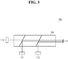
- FIGS. 2 to 4 are schematic diagrams showing a configuration of a light source unit according to the exemplary embodiment of the present disclosure.
- the light source unit 100 may include a plurality of light sources 111 , 112 , and 113 , and an optical unit 120 to synthesize (e.g., combine or collect) light generated from the plurality of light sources 111 , 112 , and 113 to generate the first light L 1 .
- the light source unit 100 may include the plurality of light sources 111 , 112 , and 113 to generate light of different colors so that light having various colors may be generated from the light source unit 100 .
- the present disclosure is not limited thereto, and the number of light sources included in the light source unit 100 or the color of the light generated from each light source may vary depending on the color of the light required in the lamp for the vehicle 1 of the present disclosure.
- the plurality of light sources 111 , 112 , and 113 of the exemplary embodiment of the present disclosure will be referred to as a first light source 111 that generates red light, a second light source 112 that generates green light, and a third light source 113 that generates blue light, respectively.
- the color of the first light L 1 generated from the light source unit 100 may be changed depending on an intensity of the light generated from each of the first to third light sources 111 , 112 , and 113 .
- the intensity of the light generated from each of the first to third light sources 111 , 112 , and 113 may refer to not only a brightness of the light, but also an on-off state of the light source.
- the optical unit 120 may generate synthetic light by synthesizing the light generated from at least one of the first to third light sources 111 , 112 , and 113 . It may be understood that the synthetic light generated by the optical unit 120 is the first light L 1 generated from the light source unit 100 .
- FIGS. 2 and 3 are examples of the case where a prism is used as the optical unit 120 .
- the optical unit 120 may transmit some of the light generated from the first to third light sources 111 , 112 , and 113 , and reflect other, thereby enabling the light generated from the first to third light sources 111 , 112 , and 113 to be synthesized.
- the optical unit 120 may transmit the light in some wavelength bands of the light generated from the first to third light sources 111 , 112 , and 113 , and may reflect the light in other wavelength bands to generate the synthetic light.
- FIG. 2 is an example in which the light generated from each of the first to third light sources 111 , 112 , and 113 is incident through different surfaces of the prism (i.e., the optical unit 120 ), in which the light generated from the first and third light sources 111 and 113 is reflected, and the light generated from the second light source 112 is transmitted, so that the synthetic light is generated.
- the prism i.e., the optical unit 120
- FIG. 3 is an example in which the light generated from the first and second light sources 111 and 112 is incident through the same surface of the prism (i.e., the optical unit 120 ), and the light generated from the third light source 113 is incident through a surface different from the first and second light sources 111 and 112 , in which the light generated from the first and second light sources 111 and 112 is reflected, and the light generated from the third light source 113 is transmitted, so that the synthetic light is generated.
- the prism i.e., the optical unit 120
- a prism may be used as the optical unit 120 .
- the present disclosure is not limited thereto, and a plurality of mirrors 121 , 122 , and 123 may be used as the optical unit 120 as shown in FIG. 4 .
- the plurality of mirrors 121 , 122 , and 123 may transmit or reflect the light generated from each of the first to third light sources 111 , 112 , and 113 to generate the synthetic light.
- each of the plurality of mirrors 121 , 122 , and 123 may reflect the light generated from any one of the first to third light sources 111 , 112 , and 113 , and may transmit the light generated from the other light sources to generate the synthetic light.
- a prism is used as the optical unit 120
- a mirror is used as the optical unit 120
- the present disclosure is not limited thereto, and both a prism and a mirror may be used in one optical unit 120 .
- various types of optical elements that enable synthesis of light as well as prisms and mirrors may be used as the optical unit 120 .
- the light adjustment unit 200 may adjust a light concentration of the light generated from the light source unit 100 . Adjusting the light concentration of the light generated from the light source unit 100 by the light adjustment unit 200 may ensure that a clear image is formed when the image is formed on a road surface around the vehicle through the lamp for the vehicle 1 of the present disclosure.
- FIG. 5 is a schematic diagram showing a configuration of a light adjustment unit according to the exemplary embodiment of the present disclosure.
- the light adjustment unit 200 may include a plurality of lenses 210 and 220 arranged along a direction of light proceeding (e.g. light projection).
- the plurality of lenses 210 and 220 will be referred to as a first lens 210 and a second lens 220 , respectively.
- the first lens 210 may be disposed closer to the light source unit 100 than the second lens 220 with respect to a proceeding path of the first light L 1 that is generated from the light source unit 100 .
- the first lens 210 and the second lens 220 may be disposed to have a coinciding optical axis Ax.
- an effective area of the second lens 220 may be formed to be smaller than an effective area of the first lens 210 .
- This configuration may increase the light concentration while the light incident from the light source unit 100 passes through the first lens 210 and the second lens 220 .
- the effective area of the lens may refer to an area projected on a plane perpendicular to an optical axis of the lens, through which the light from the light source 110 actually passes.
- the effective area may be, within the entire area of the lens projected on the plane perpendicular to the optical axis of the lens, the part that actually affects a path of incident light.
- the effective area of the lens may be an area having at least one radius around the optical axis of the lens.
- the effective area of the lens may be the entire area of the lens, or may be a partial area thereof.
- FIG. 5 is an example in which the entire areas of the first lens 210 and the second lens 220 serve as the effective areas, the first lens 210 is formed larger than the second lens 220 so that the effective area A 1 of the first lens 210 is larger than the effective area A 2 of the second lens 220 , and thus, a focal length of the second lens 220 is shorter than a focal length of the first lens 210 .
- the first lens 210 and the second lens 220 may have different physical sizes.
- the present disclosure is not limited thereto, and even if the first lens 210 and the second lens 220 have the same or substantially same physical size in consideration of assembly or the like, the first lens 210 may have a larger effective area than the second lens 220 by adjusting optical properties such as curvatures of an incident or emitting surface of the first lens 210 and the second lens 220 . It may be understood that different sizes of the first lens 210 and the second lens 220 mean that lengths of at least one radial direction are different from each other with respect to the optical axis Ax.
- a shape of the lens and a shape of the effective area may be the same.
- the present disclosure is not limited thereto, and the shape of the lens and the shape of the effective area may be different.
- the effective area may have a circular shape or a non-circular shape.
- the shape of the lens and the shape of the effective area are not limited to the examples described above, and the lens and the effective area may have a circular shape, a polygonal shape, or a combination thereof.
- the first lens 210 and the second lens 220 may be used as the light adjustment unit 200 .
- the first lens 210 , the second lens 220 , the effective area of the first lens 210 , and the effective area of the second lens 220 may have the same shape, or one of them may have a different shape from the other.
- FIG. 6 is a schematic diagram showing an optical path of the light adjustment unit according to the exemplary embodiment of the present disclosure.
- the first light L 1 that is generated from the light source unit 100 may proceed substantially parallel to the optical axis Ax of the first lens 210 , may be incident on the first lens 210 , and then, may be concentrated on a focal point F disposed between the first lens 210 and the second lens 220 . Subsequently, the first light L 1 may be converted into a second light L 2 which is parallel to the optical axis Ax of the second lens 220 and be emitted by the second lens 220 .
- the light adjustment unit 200 may adjust the light to cause the light concentration of the second light L 2 to be greater than the light concentration of the first light L 1 . Accordingly, the focal length may be increased, so that even if the position where the image is formed on the road surface around the vehicle changes, a clear image may be formed.
- the entire areas of the first lens 210 and the second lens 220 may serve as the effective areas, and the first lens 210 may be larger than the second lens 220 to allow the first lens 210 to have a larger effective area than the second lens 220 , and thereby to allow the first lens 210 and the second lens 220 to have different focal lengths.
- the present disclosure is not limited thereto, and even if the first lens 210 and the second lens 220 have the same size, the first lens 210 may have a larger effective area than the second lens 220 by adjusting optical properties such as curvatures of an incident or emitting surface of at least one of the first lens 210 and the second lens 220 as shown in FIG. 7 . Accordingly, the light may be adjusted to cause the light concentration of the second light L 2 to be greater than the light concentration of the first light L 1 .
- the movable mirror unit 300 may adjust a direction of the second light L 2 , the light concentration of which has been adjusted by the light adjustment unit 200 .
- a direction of the light that is reflected by the movable mirror unit 300 may be changed depending on a position of the movable mirror unit 300 . Accordingly, the position where the image is formed on the road surface around the vehicle may be changed.
- the movable mirror 300 initially has a position as shown in FIG. 8
- the direction of the light that is reflected by the movable mirror 300 may be changed. Therefore, the position where the image is formed on the road surface around the vehicle may be changed.
- the dotted arrows in FIGS. 9 and 10 indicate a reflection direction when the movable mirror unit 300 is at the initial position shown in FIG. 8 , and the dotted arrows may be used for comparison with a reflection direction when the position of the movable mirror 300 is changed as shown in FIGS. 9 and 10 .
- the movable mirror unit 300 is rotated to adjust its position.
- this configuration is only an example for helping the understanding of the present disclosure.
- the present disclosure is not limited thereto, and the movable mirror unit 300 may be adjusted in position by rotational motion, linear motion, or a combination thereof.
- the first light L 1 generated from the light source unit 100 is directly incident on the light adjustment unit 200 .
- the present disclosure is not limited thereto, and when it is necessary to change the path of the light due to a layout of the lamp for the vehicle 1 of the present disclosure or for design reasons or the like, the first light L 1 generated from the light source unit 100 may be reflected by an additional mirror unit 400 and may proceed to the light adjustment unit 200 , as shown in FIG. 11 .
- the movable mirror unit 300 and the mirror unit 400 may be disposed to face each other to allow the light reflected by the mirror unit 400 to proceed to the movable mirror unit 300 through the light adjustment unit 200 .
- FIG. 11 it is described as an example in which the mirror unit 400 is formed as a single unit.
- this configuration is only an example for helping the understanding of the present disclosure.
- the present disclosure is not limited thereto, and two or more mirror units 400 may be provided to change the path of light.
- FIG. 12 is a schematic diagram showing the position where the light is irradiated (e.g., projected) to the road surface around the vehicle from the lamp for the vehicle according to the exemplary embodiment of the present disclosure
- FIG. 12 shows an example where the lamp for the vehicle of the present disclosure is installed on the front of the vehicle and is provided at a head lamp that irradiates light in the driving direction of the vehicle.
- the second light L 2 that is concentrated by the light adjustment unit 200 may be irradiated to a first position P 1 or a second position P 2 depending on the position of the movable mirror unit 300 , to form a predetermined image.
- FIG. 12 it is described as an example in which the light is irradiated to either the first position P 1 or the second position P 2 .
- the present disclosure is not limited thereto, and the position to which the light is irradiated may be added, removed, or changed depending on the position of the movable mirror 300 .
- the light when the light is irradiated to the first position P 1 or the second position P 2 by the movable mirror unit 300 , the light may be concentrated by the light adjustment unit 200 , so that the focal length is relatively long. Therefore, a clearer image may be formed than when the focal length is shorter. Accordingly, more accurate information may be delivered both when the image is formed at the first position P 1 and when the image is formed at the second position P 2 .
- the lamp for the vehicle 1 of the present disclosure when the lamp for the vehicle 1 of the present disclosure is provided in the head lamp, it may be accommodated in an accommodation space formed by a lamp housing (not shown) of the head lamp and a cover lens (not shown) coupled to the lamp housing. Therefore, a better protection from external impact may be provided. In addition, since no separate structure is required to prevent foreign matters such as dust from entering from the exterior, the configuration may be simplified, and the cost may be reduced.
- FIG. 12 it is described as an example in which the lamp for the vehicle 1 of the present disclosure is provided in the head lamp.
- the present disclosure is not limited thereto, and the lamp for the vehicle 1 of the present disclosure may be accommodated in a space formed by the lamp housing and the cover lens of various lamps installed in the vehicle.
- the lamp for the vehicle 1 of the present disclosure may be provided in plurality in order to form an image of a predetermined shape on a road surface around the vehicle by the lamp for the vehicle 1 of the present disclosure.
- the position of the movable mirror unit 300 of each of the plurality of vehicle lamps 1 may be adjusted to form each image having a desired shape.
Abstract
Description
Claims (10)
Applications Claiming Priority (2)
| Application Number | Priority Date | Filing Date | Title |
|---|---|---|---|
| KR1020190174764A KR20210082632A (en) | 2019-12-26 | 2019-12-26 | Lamp for vehicle |
| KR10-2019-0174764 | 2019-12-26 |
Publications (2)
| Publication Number | Publication Date |
|---|---|
| US20210199261A1 US20210199261A1 (en) | 2021-07-01 |
| US11326759B2 true US11326759B2 (en) | 2022-05-10 |
Family
ID=76310459
Family Applications (1)
| Application Number | Title | Priority Date | Filing Date |
|---|---|---|---|
| US17/071,517 Active US11326759B2 (en) | 2019-12-26 | 2020-10-15 | Lamp for vehicle having a movable mirror and a light adjustment unit |
Country Status (4)
| Country | Link |
|---|---|
| US (1) | US11326759B2 (en) |
| KR (1) | KR20210082632A (en) |
| CN (1) | CN113048444A (en) |
| DE (1) | DE102020214973A1 (en) |
Citations (4)
| Publication number | Priority date | Publication date | Assignee | Title |
|---|---|---|---|---|
| US20160039330A1 (en) * | 2014-08-08 | 2016-02-11 | Automotive Lighting Reutlingen Gmbh | Projection light module for a motor vehicle headlight |
| US9777901B2 (en) * | 2013-02-07 | 2017-10-03 | Zkw Group Gmbh | Headlight for a motor vehicle and method for distributing light |
| US10179534B2 (en) * | 2016-12-07 | 2019-01-15 | Stanley Electric Co., Ltd. | Vehicle lighting apparatus |
| US20190113200A1 (en) * | 2016-07-29 | 2019-04-18 | Panasonic Intellectual Property Management Co., Ltd. | Light emission device and illumination device |
Family Cites Families (4)
| Publication number | Priority date | Publication date | Assignee | Title |
|---|---|---|---|---|
| KR20120055030A (en) | 2010-11-22 | 2012-05-31 | 현대모비스 주식회사 | Head lamp for vehicles |
| CN102287647A (en) * | 2011-08-03 | 2011-12-21 | 广州市雅江光电设备有限公司 | Light-emitting diode (LED) optical system and method for mixing light and zooming by using same |
| CN103900003A (en) * | 2012-12-26 | 2014-07-02 | 鸿富锦精密工业(深圳)有限公司 | Automobile lamp system |
| CN208457845U (en) * | 2018-08-15 | 2019-02-01 | 华域视觉科技(上海)有限公司 | A kind of headlamp mould group and automobile |
-
2019
- 2019-12-26 KR KR1020190174764A patent/KR20210082632A/en active Search and Examination
-
2020
- 2020-07-31 CN CN202010755808.6A patent/CN113048444A/en active Pending
- 2020-10-15 US US17/071,517 patent/US11326759B2/en active Active
- 2020-11-27 DE DE102020214973.9A patent/DE102020214973A1/en not_active Ceased
Patent Citations (4)
| Publication number | Priority date | Publication date | Assignee | Title |
|---|---|---|---|---|
| US9777901B2 (en) * | 2013-02-07 | 2017-10-03 | Zkw Group Gmbh | Headlight for a motor vehicle and method for distributing light |
| US20160039330A1 (en) * | 2014-08-08 | 2016-02-11 | Automotive Lighting Reutlingen Gmbh | Projection light module for a motor vehicle headlight |
| US20190113200A1 (en) * | 2016-07-29 | 2019-04-18 | Panasonic Intellectual Property Management Co., Ltd. | Light emission device and illumination device |
| US10179534B2 (en) * | 2016-12-07 | 2019-01-15 | Stanley Electric Co., Ltd. | Vehicle lighting apparatus |
Also Published As
| Publication number | Publication date |
|---|---|
| US20210199261A1 (en) | 2021-07-01 |
| CN113048444A (en) | 2021-06-29 |
| KR20210082632A (en) | 2021-07-06 |
| DE102020214973A1 (en) | 2021-07-01 |
Similar Documents
| Publication | Publication Date | Title |
|---|---|---|
| CN108302477B (en) | Headlamp apparatus for vehicle | |
| JP6659456B2 (en) | Vehicle lighting | |
| CN215174752U (en) | Vehicle lamp | |
| US11608955B2 (en) | Lamp for vehicle | |
| US11359787B2 (en) | Lamp for vehicle | |
| US11326759B2 (en) | Lamp for vehicle having a movable mirror and a light adjustment unit | |
| US10808916B2 (en) | Lighting device including an imaging unit having inclined optical axis with respect to horizontal line | |
| JP2011003515A (en) | Vehicular headlight for low beam | |
| US10480740B2 (en) | Light device, especially a projector system of a headlight for motor vehicles | |
| US20230066763A1 (en) | Lamp module and vehicle lamp including the same | |
| US11655951B2 (en) | Lamp for vehicle | |
| US10883689B2 (en) | Vehicular headlamp | |
| KR101489208B1 (en) | Automotive lamp | |
| KR20220006316A (en) | Lamp for vehicle | |
| US11499691B1 (en) | Lamp for vehicle | |
| US11668449B2 (en) | Lamp for vehicle | |
| US11578849B2 (en) | Lamp for vehicle | |
| JP5417424B2 (en) | Vehicle headlight for low beam | |
| US11898715B2 (en) | Lamp for vehicle having a plurality of light source modules arranged in width direction with an optical unit with a plurality of corresponding lenses grouped so as the emit multiple beam patterns | |
| US11808428B2 (en) | Lamp module and lamp for vehicle including the same | |
| US20220402424A1 (en) | Lighting device | |
| US20230280012A1 (en) | Lighting module for a vehicle headlamp | |
| KR20220056471A (en) | Lamp for vehicle | |
| KR20220042621A (en) | Lamp for vehicle | |
| CN116202049A (en) | Lamp for vehicle |
Legal Events
| Date | Code | Title | Description |
|---|---|---|---|
| FEPP | Fee payment procedure |
Free format text: ENTITY STATUS SET TO UNDISCOUNTED (ORIGINAL EVENT CODE: BIG.); ENTITY STATUS OF PATENT OWNER: LARGE ENTITY |
|
| AS | Assignment |
Owner name: SL CORPORATION, KOREA, REPUBLIC OF Free format text: ASSIGNMENT OF ASSIGNORS INTEREST;ASSIGNORS:PARK, HYE JIN;LEE, JONG MIN;REEL/FRAME:054102/0188 Effective date: 20200914 |
|
| STPP | Information on status: patent application and granting procedure in general |
Free format text: APPLICATION DISPATCHED FROM PREEXAM, NOT YET DOCKETED |
|
| STPP | Information on status: patent application and granting procedure in general |
Free format text: DOCKETED NEW CASE - READY FOR EXAMINATION |
|
| STPP | Information on status: patent application and granting procedure in general |
Free format text: NON FINAL ACTION MAILED |
|
| STPP | Information on status: patent application and granting procedure in general |
Free format text: RESPONSE TO NON-FINAL OFFICE ACTION ENTERED AND FORWARDED TO EXAMINER |
|
| STPP | Information on status: patent application and granting procedure in general |
Free format text: NOTICE OF ALLOWANCE MAILED -- APPLICATION RECEIVED IN OFFICE OF PUBLICATIONS |
|
| STPP | Information on status: patent application and granting procedure in general |
Free format text: PUBLICATIONS -- ISSUE FEE PAYMENT VERIFIED |
|
| STCF | Information on status: patent grant |
Free format text: PATENTED CASE |