US11326708B2 - Solenoid valve - Google Patents
Solenoid valve Download PDFInfo
- Publication number
- US11326708B2 US11326708B2 US16/986,671 US202016986671A US11326708B2 US 11326708 B2 US11326708 B2 US 11326708B2 US 202016986671 A US202016986671 A US 202016986671A US 11326708 B2 US11326708 B2 US 11326708B2
- Authority
- US
- United States
- Prior art keywords
- valve body
- seal member
- movable core
- housing
- opening
- Prior art date
- Legal status (The legal status is an assumption and is not a legal conclusion. Google has not performed a legal analysis and makes no representation as to the accuracy of the status listed.)
- Active
Links
Images


Classifications
-
- F—MECHANICAL ENGINEERING; LIGHTING; HEATING; WEAPONS; BLASTING
- F16—ENGINEERING ELEMENTS AND UNITS; GENERAL MEASURES FOR PRODUCING AND MAINTAINING EFFECTIVE FUNCTIONING OF MACHINES OR INSTALLATIONS; THERMAL INSULATION IN GENERAL
- F16K—VALVES; TAPS; COCKS; ACTUATING-FLOATS; DEVICES FOR VENTING OR AERATING
- F16K31/00—Actuating devices; Operating means; Releasing devices
- F16K31/02—Actuating devices; Operating means; Releasing devices electric; magnetic
- F16K31/06—Actuating devices; Operating means; Releasing devices electric; magnetic using a magnet, e.g. diaphragm valves, cutting off by means of a liquid
- F16K31/0644—One-way valve
- F16K31/0655—Lift valves
-
- F—MECHANICAL ENGINEERING; LIGHTING; HEATING; WEAPONS; BLASTING
- F16—ENGINEERING ELEMENTS AND UNITS; GENERAL MEASURES FOR PRODUCING AND MAINTAINING EFFECTIVE FUNCTIONING OF MACHINES OR INSTALLATIONS; THERMAL INSULATION IN GENERAL
- F16K—VALVES; TAPS; COCKS; ACTUATING-FLOATS; DEVICES FOR VENTING OR AERATING
- F16K1/00—Lift valves or globe valves, i.e. cut-off apparatus with closure members having at least a component of their opening and closing motion perpendicular to the closing faces
- F16K1/32—Details
- F16K1/34—Cutting-off parts, e.g. valve members, seats
- F16K1/36—Valve members
- F16K1/38—Valve members of conical shape
-
- F—MECHANICAL ENGINEERING; LIGHTING; HEATING; WEAPONS; BLASTING
- F16—ENGINEERING ELEMENTS AND UNITS; GENERAL MEASURES FOR PRODUCING AND MAINTAINING EFFECTIVE FUNCTIONING OF MACHINES OR INSTALLATIONS; THERMAL INSULATION IN GENERAL
- F16K—VALVES; TAPS; COCKS; ACTUATING-FLOATS; DEVICES FOR VENTING OR AERATING
- F16K1/00—Lift valves or globe valves, i.e. cut-off apparatus with closure members having at least a component of their opening and closing motion perpendicular to the closing faces
- F16K1/32—Details
- F16K1/34—Cutting-off parts, e.g. valve members, seats
- F16K1/42—Valve seats
-
- F—MECHANICAL ENGINEERING; LIGHTING; HEATING; WEAPONS; BLASTING
- F16—ENGINEERING ELEMENTS AND UNITS; GENERAL MEASURES FOR PRODUCING AND MAINTAINING EFFECTIVE FUNCTIONING OF MACHINES OR INSTALLATIONS; THERMAL INSULATION IN GENERAL
- F16K—VALVES; TAPS; COCKS; ACTUATING-FLOATS; DEVICES FOR VENTING OR AERATING
- F16K31/00—Actuating devices; Operating means; Releasing devices
- F16K31/02—Actuating devices; Operating means; Releasing devices electric; magnetic
- F16K31/06—Actuating devices; Operating means; Releasing devices electric; magnetic using a magnet, e.g. diaphragm valves, cutting off by means of a liquid
- F16K31/0603—Multiple-way valves
- F16K31/0624—Lift valves
- F16K31/0634—Lift valves with fixed seats positioned between movable valve members
-
- F—MECHANICAL ENGINEERING; LIGHTING; HEATING; WEAPONS; BLASTING
- F16—ENGINEERING ELEMENTS AND UNITS; GENERAL MEASURES FOR PRODUCING AND MAINTAINING EFFECTIVE FUNCTIONING OF MACHINES OR INSTALLATIONS; THERMAL INSULATION IN GENERAL
- F16K—VALVES; TAPS; COCKS; ACTUATING-FLOATS; DEVICES FOR VENTING OR AERATING
- F16K31/00—Actuating devices; Operating means; Releasing devices
- F16K31/02—Actuating devices; Operating means; Releasing devices electric; magnetic
- F16K31/06—Actuating devices; Operating means; Releasing devices electric; magnetic using a magnet, e.g. diaphragm valves, cutting off by means of a liquid
- F16K31/0686—Braking, pressure equilibration, shock absorbing
- F16K31/0696—Shock absorbing, e.g. using a dash-pot
-
- F—MECHANICAL ENGINEERING; LIGHTING; HEATING; WEAPONS; BLASTING
- F16—ENGINEERING ELEMENTS AND UNITS; GENERAL MEASURES FOR PRODUCING AND MAINTAINING EFFECTIVE FUNCTIONING OF MACHINES OR INSTALLATIONS; THERMAL INSULATION IN GENERAL
- F16K—VALVES; TAPS; COCKS; ACTUATING-FLOATS; DEVICES FOR VENTING OR AERATING
- F16K2200/00—Details of valves
- F16K2200/30—Spring arrangements
- F16K2200/302—Plurality of biasing means, e.g. springs, for opening or closing single valve member
Definitions
- the present invention relates to a solenoid valve that opens and closes a channel of a pressurized fluid.
- PTL 1 discloses, as one type of such solenoid valves, a two-way valve that can be applied to a fluid supply valve or the like used for a pressured fluid that is used by a high-pressure washing apparatus or high-pressure fluid supply apparatus.
- FIGS. 6 and 7 are side sectional views each showing the arrangement of a conventional solenoid valve 1000 .
- FIG. 6 shows a closed state of the solenoid valve 1000 .
- FIG. 7 shows an open state of the solenoid valve 1000 .
- the solenoid valve 1000 has a shaft-shaped stem 1001 extending through the center of the valve.
- a valve body 1003 formed on the stem 1001 is pressed against a seal member 1005 with the force of a compression coil spring 1007 to close a path from an inlet port 1009 to an outlet port 1011 , thus keeping the solenoid valve 1000 in the closed state.
- the coil 1013 attracts an umbrella-shaped movable core 1015 made of a magnetic material by a distance corresponding to gap d.
- a rod-shaped movable core 1017 pushes down the stem 1001 against the force of the compression coil spring 1007 to separate the valve body 1003 from the seal member 1005 .
- a weak compression coil spring 1023 is arranged between the umbrella-shaped movable core 1015 and a cover 1025 to suppress the vibration of the umbrella-shaped movable core 1015 .
- adjusting the mounting length of the compression coil spring 1007 by rotating an adjusting screw 1019 will adjust the force with which the valve body 1003 is pressed against the seal member 1005 .
- rotating an adjusting screw 1021 will adjust the size of the gap d between the umbrella-shaped movable core 1015 and the coil 1013 , thereby stabilizing the opening/closing operation of the solenoid valve 1000 .
- the present invention has been made in consideration of the above problem and improves the operation accuracy of the solenoid valve.
- a solenoid valve comprising: an inlet port into which a fluid flows; an outlet port from which a fluid flows; a seal member arranged in a channel of a fluid between the inlet port and the outlet port and having an opening; a valve body configured to open and close the opening of the seal member to open and close the channel; a first spring configured to bias the valve body against the seal member so as to close the opening of the seal member; electromagnetic driving device, including an umbrella-shaped movable core configured to move the valve body and an electromagnetic coil configured to attract the umbrella-shaped movable core, for operating by being energized by the electromagnetic coil so as to open the opening of the seal member by attracting the umbrella-shaped movable core and separating the valve body from the opening; and a second spring configured to exert, on the umbrella-shaped movable core, a spring force weaker than a spring force of the first spring in a direction opposite to a biasing direction of the first spring, wherein the second spring is provided with rotation preventing device for preventing the umbrella-shaped
- FIG. 1 is a side sectional view showing the arrangement of a solenoid valve according to an embodiment of the present invention
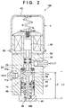
- FIG. 2 is a side sectional view showing the arrangement of the solenoid valve according to the embodiment of the present invention
- FIG. 3A is a view showing the removed compression coil spring portion of an electromagnetic driving unit
- FIG. 3B is a view showing the removed compression coil spring portion of the electromagnetic driving unit
- FIG. 3C is a view showing the removed compression coil spring portion of the electromagnetic driving unit
- FIG. 4 is an enlarged view of the spacer of the compression coil spring
- FIG. 5A is a view showing the arrangement of a seal member
- FIG. 5B is a view showing the arrangement of the seal member
- FIG. 5C is a view showing the arrangement of the seal member
- FIG. 5D is a view showing the arrangement of the seal member
- FIG. 6 is a side sectional view showing the arrangement of a conventional solenoid valve.
- FIG. 7 is a side sectional view showing the arrangement of the conventional solenoid valve.
- FIGS. 1 and 2 are side sectional views each showing the arrangement of a solenoid valve 100 according to an embodiment of the present invention.
- FIG. 1 shows the closed state of the solenoid valve 100 .
- FIG. 2 shows the open state of the solenoid valve 100 .
- the solenoid valve 100 is a two-way valve that circulates a liquid, gas, or the like that can be used for a supply valve used for a pressurized fluid used by, for example, a high-pressure washing apparatus and a high-pressure test apparatus. Note, however, that the present invention can also be applied to a three-way valve as well as a two-way valve.
- the solenoid valve 100 roughly includes a housing 1 constituting the main body of the valve and an electromagnetic driving unit 2 that is fixed to the housing 1 with bolts and the like and serves to open and close the valve.
- the housing 1 is formed by processing a metal such as aluminum and has a tunnel-shaped through hole 13 through which a stem 11 as a shaft that opens and closes the valve extends. A fluid such as a liquid or gas flows inside the through hole 13 , and the stem 11 moves to open and close the flow.
- An inlet port 15 and an outlet port 17 are formed in side portions of the housing 1 .
- the inlet port 15 allows a fluid to flow into the through hole 13 .
- the outlet port 17 allows the fluid to flow out from the through hole 13 .
- Female threads are formed on the inner surfaces of the inlet port 15 and the outlet port 17 .
- Ferrules 19 and 21 for fixing connecting pipes between a fluid source and a supply destination are fixed in these portions by being screwed.
- a valve body 11 c having conical tapered surfaces 11 a and 11 b is formed in the intermediated portion of the stem 11 on both sides of the stem 11 in a direction along the central axis (the up-down direction in FIG. 1 ).
- the electromagnetic driving unit 2 enables the stem 11 to slide in the up-down direction in FIG. 1 as indicated by an arrow A.
- the upper tapered surface 11 a of the valve body 11 c is pressed against an annular seal member 23 mounted in the through hole 13 , as shown in FIG. 1 , thereby shutting off the flow of a fluid flowing from the inlet port 15 to the outlet port 17 . That is, the solenoid valve 100 is set in the closed state.
- the upper tapered surface 11 a of the valve body 11 c separates from the seal member 23 to form a gap 25 between the seal member 23 and the valve body 11 c. This forms a channel to make the fluid supplied to the inlet port 15 flow into the outlet port 17 through the gap 25 , thereby setting the solenoid valve 100 in the open state.
- a first piston 29 wearing an O-ring 27 for sealing is formed on the upper end portion of the stem 11 .
- the first piston 29 slides along the inside of an upper portion 13 a of the through hole 13 .
- a second piston 33 wearing an O-ring 31 for sealing is formed on the lower end portion of the stem 11 .
- a guide member 37 wearing an O-ring 35 for sealing is arranged in a lower portion 13 b of the through hole 13 .
- the second piston 33 slides along the inside of the guide member 37 .
- the guide member 37 is arranged on the seal member 23 through a sleeve 39 .
- a female thread 41 is formed on the lower portion of the housing 1 , and a fixing screw 43 for fixing the guide member 37 is screwed into the lower portion. Screwing the fixing screw 43 into the female thread 41 will press the guide member 37 , the sleeve 39 , and the seal member 23 against a stepped portion 1 a of the housing 1 , thereby fixing them.
- a cylindrical space 43 a is formed inside the fixing screw 43 .
- a compression coil spring 45 is arranged in the cylindrical space 43 a.
- the fixing screw 43 functions as a case member that positions the compression coil spring 45 that is an elastic member.
- the compression coil spring 45 biases an inner bottom surface 43 b of the fixing screw 43 in a direction to push up the lower surface of the second piston 33 of the stem 11 . Accordingly, in a natural state in which the force of the electromagnetic driving unit 2 does not act, the stem 11 is pushed up with the force of the compression coil spring 45 to the upper side in FIG. 1 . As a result, the valve body 11 c is pressed against the seal member 23 with the force of the compression coil spring 45 to generate a force to close the solenoid valve 100 .
- the solenoid valve 100 is a normal close two-way valve that is closed in a natural state.
- an annular spacer 46 is held between the lower surface of the compression coil spring 45 and the inner bottom surface 43 b of the fixing screw 43 . The function of this spacer will be described later.
- the electromagnetic driving unit 2 has a fixed core 53 made of a magnetic material such as iron around which a conducting wire 51 is wound in the form of a coil. Although described in detail later, the fixed core 53 is fixed to the housing 1 through a spacer 54 with bolts and the like. A through hole 53 a is formed so as to extend through the central portion of the fixed core 53 in the up-down direction. A rod-shaped movable core 55 made of a nonmagnetic material which serves to push down the upper surface of the first piston 29 of the stem 11 is inserted into the through hole 53 a of the fixed core 53 .
- An umbrella-shaped movable core 57 made of a magnetic material which is attracted with the magnetic force generated in the fixed core 53 when the conducting wire 51 is energized is fixed in the upper end portion of the rod-shaped movable core 55 by press fitting.
- a female thread 55 a is formed on the upper end portion of the rod-shaped movable core 55 . Screwing a bolt 58 into the female thread 55 a will fix a receiving seat 61 for receiving the bottom surface of a compression coil spring 59 .
- a gap d is formed between a lower surface 57 a of the umbrella-shaped movable core 57 and an upper surface 53 b of the fixed core 53 .
- the umbrella-shaped movable core 57 moves downward by the distance corresponding to the gap d against the force of the compression coil spring 45 , and the rod-shaped movable core 55 pushes down the stem 11 by the distance corresponding to the gap d. This separates the valve body 11 c from the seal member 23 to set the solenoid valve 100 in the open state.
- a bottomed cylindrical cover (cover member) 63 is mounted on the outside of the fixed core 53 of the electromagnetic driving unit 2 so as to cover the electromagnetic driving unit 2 and is fixed to the fixed core 53 with screws 65 and the like.
- the compression coil spring 59 biases the umbrella-shaped movable core 57 against the cover 63 with a force weaker than that pushes up the lower compression coil spring 45 . That is, the compression coil spring 59 exerts a weak force on the umbrella-shaped movable core 57 in a direction opposite to the biasing direction of the compression coil spring 45 . This makes the compression coil spring 59 prevent the vibration of the umbrella-shaped movable core 57 without pushing down the umbrella-shaped movable core 57 against the force of the compression coil spring 45 .
- FIGS. 3A to 3C are views each showing an extracted portion on which the compression coil spring 59 of the electromagnetic driving unit 2 is mounted.
- FIG. 3A is a view showing the compression coil spring 59 mounted on the umbrella-shaped movable core 57 through the receiving seat 61 when viewed from obliquely above.
- FIG. 3B is a view showing the compression coil spring 59 when viewed from a side.
- FIG. 3C is a view showing how the compression coil spring 59 is assembled.
- the compression coil spring 59 is wound in the form of an almost circular cone such that the bottom portion has a large diameter and gradually decreases in diameter upward.
- a first locking portion 59 a inwardly bent from the circumference of the coil is formed at one end portion of the coil which comes into contact with this circular conical top portion.
- a pair of protruding portions 63 a and 63 b are formed on the ceiling surface of the cover 63 so as to sandwich the first locking portion 59 a from both sides.
- the first locking portion 59 a of the compression coil spring 59 is sandwiched between the pair of protruding portions 63 a and 63 b to inhibit the rotation of the compression coil spring 59 with respect to the cover 63 .
- a second locking portion 59 b outwardly bent from the circumference of the coil is formed at the proximal end portion (the other end portion) of the compression coil spring 59 .
- the plate-shaped receiving seat 61 is partly bent upward, and a locking hole 61 a is formed in the bent portion. As shown in FIG. 3C , inserting the second locking portion 59 b of the compression coil spring 59 into the locking hole 61 a will prevent the umbrella-shaped movable core 57 from rotating with respect to the compression coil spring 59 through the receiving seat 61 .
- the first and second locking portions 59 a and 59 b of the compression coil spring 59 , the pair of protruding portions 63 a and 63 b of the cover 63 , and the locking hole 61 a prevent the umbrella-shaped movable core 57 from rotating with respect to the cover 63 , eventually, with respect to the fixed core 53 .
- the conventional solenoid valve 1000 shown in FIG. 6 has no structure for preventing the umbrella-shaped movable core 1015 from rotating with respect to the coil 1013 (core).
- the umbrella-shaped movable core 1015 There is originally a slight gap between the outer diameter of the rod-shaped movable core 1021 of the umbrella-shaped movable core 1015 and the inner diameter of the through hole of the core so as to allow the rod-shaped movable core 1021 to slide.
- the umbrella-shaped movable core 1015 sometimes slightly tilts with respect to the core by an amount corresponding to the gap.
- the size of the gap d between the umbrella-shaped movable core 1015 and the core varies, thus sometimes causing variations in operation and attraction timing when the umbrella-shaped movable core is attracted to the core.
- the first and second locking portions 59 a and 59 b of the compression coil spring 59 , the pair of protruding portions 63 a and 63 b of the cover 63 , and the locking hole 61 a prevent the umbrella-shaped movable core 57 from rotating with respect to the fixed core 53 , and hence it is possible to accurately and stably control the operation and the attraction timing when the umbrella-shaped movable core 57 is attracted to the fixed core 53 .
- the proximal end portion of the rod-shaped movable core 55 which is fixed to the umbrella-shaped movable core 57 by press fitting is formed into a large-diameter portion 55 c by being made thicker than a distal end portion 55 b of the rod-shaped movable core 55 .
- the distal end portion 55 b and the large-diameter portion 55 c of the rod-shaped movable core 55 are integrally formed. Forming the proximal end portion thick in this manner will reduce the tilt of the rod-shaped movable core 55 with respect to the fixed core 53 assuming that the gap and the fitting length remain the same when the rod-shaped movable core 55 is fitted in the fixed core 53 .
- the conventional solenoid valve is configured such that the mounting length of the compression coil spring 1007 by which the valve body 1003 is pressed against the seal member 1005 is adjusted with the adjusting screw 1019 .
- adjusting this mounting length will uniform the force with which the valve body is pressed against the seal member, thereby accurately controlling the timing of opening/closing the solenoid valve.
- this adjustment is very delicate, and hence it is very difficult to uniform the characteristics of a plurality of solenoid valves.
- adjustment sometimes changes. This inevitably causes a certain degree of error in the timing of opening/closing the valve in the conventional structure.
- This embodiment uses a structure for solving this problem.
- the respective components are manufactured by accurately managing dimensional precision instead of adjusting the mounting length of the compression coil spring 45 with the adjusting screw.
- the dimensions of the manufactured components are then actually measured, and a total dimensional error caused by the tolerance accumulation of the respective components is then adjusted by inserting the spacer 46 between the lower surface of the compression coil spring 45 and the inner bottom surface (support surface) 43 b of the fixing screw 43 .
- a dimension L 1 from the inner bottom surface 43 b of the fixing screw 43 on which the compression coil spring 45 is seated to that surface of the seal member 23 with which the valve body 11 c is in contact is equal to the sum of the dimension from the inner bottom surface 43 b of the fixing screw 43 to the upper end of the fixing screw 43 , the dimension of the guide member 37 in the longitudinal direction, and the dimension of the sleeve 39 in the longitudinal direction.
- a total dimension is acquired by measuring the dimensions of the respective components.
- the thickness of the spacer 46 is adjusted in accordance with these dimensions such that the mounting length of the compression coil spring 45 falls within an error of about 0.05 mm with respect to, for example, a design value.
- a dimensional error of, for example, about 0.3 mm at maximum occurs.
- six types of spacers are prepared, which differ in thickness from, for example, 0.05 mm to 0.3 mm in increments of 0.05 mm.
- An optimal spacer is selected from the six types of spacers based on the actually measured dimensional values of the respective components described above and inserted between the lower surface of the compression coil spring 45 and the inner bottom surface 43 b of the fixing screw 43 . This makes it possible to accurately set the mounting length of the compression coil spring 45 . This adjustment will not change afterward.
- FIG. 4 is a view showing the actual shape of the spacer 46 .
- the spacer 46 has a disk-shaped outer peripheral portion 46 a and a central portion 46 b protruding upward in a columnar shape.
- the outer peripheral portion of the central portion 46 b is chamfered to facilitate fitting of the inner peripheral surface of the compression coil spring 45 .
- the inner peripheral surface of the compression coil spring 45 is guided by the central portion 46 b of the annular spacer 46 to position the compression coil spring 45 in the center of the inside of the disk-shaped space 43 a (inside the space) so as to form a gap S 1 between the outer peripheral portion of the compression coil spring 45 and the cylindrical space 43 a of the fixing screw 43 .
- the gap S 1 is set to be larger than a space S 2 between the outer peripheral portion 46 a of the spacer 46 and the cylindrical space 43 a. This prevents, for example, the loss of force and the occurrence of dust by sliding between the outer peripheral surface of the compression coil spring 45 and the inner peripheral surface of the cylindrical space 43 a when the compression coil spring 45 expands and contracts. Dust is a serious problem for a high-accuracy solenoid valve.
- the above arrangement according to this embodiment can effectively prevent the generation of dust. This can also prevent the loss of force of the compression coil spring 45 .
- a through hole 46 c is formed in the central portion of the spacer 46 , and a through hole 43 c is formed in the bottom surface of the fixing screw 43 . This arrangement is configured to escape the pressure in the cylindrical space 43 a.
- the respective components are manufactured by accurately managing the dimensional accuracy of the components instead of adjusting the gap d between the umbrella-shaped movable core 57 and the fixed core 53 with the adjusting screw.
- the dimensions of the manufactured components are then actually measured, and a total dimensional error caused by the tolerance accumulation of the respective components is then adjusted by inserting the spacer 54 between the lower surface of the fixed core 53 and the upper surface of the housing 1 .
- a dimension L 3 from a point at which the valve body 11 c comes into contact with the seal member 23 to the lower surface 57 a of the umbrella-shaped movable core 57 is equal to the sum of the dimension from a point at which the valve body 11 c comes into contact with the seal member 23 to the upper surface of the first piston 29 and the dimension from the distal end of the rod-shaped movable core 55 to the mounting stepped portion of the umbrella-shaped movable core 57 .
- Measuring the dimensions of the respective components will obtain the total dimension of this portion.
- the thickness of the spacer 54 is adjusted such that the dimension of the gap d falls within an error of about 0.05 mm.
- a dimensional error of, for example, 0.3 mm at maximum occurs.
- six types of spacers are prepared, which differ in thickness from, for example, 0.05 mm to 0.3 mm in increments of 0.05 mm.
- An optimal spacer is selected from the six types of spacers based on the actually measured dimensional values of the respective components described above and inserted between the lower surface of the fixed core 53 and the upper surface of the housing 1 . This makes it possible to accurately set the size of the gap d between the lower surface 57 a of the umbrella-shaped movable core 57 and the upper surface of the fixed core 53 . This adjustment will not change afterward.
- adjustment is performed by means of the dimensional accuracy of the components and the spacers in the above manner to reduce the time and effort for adjustment and prevent the adjustment from changing afterward.
- FIGS. 5A to 5D are views each showing the structure of the seal member 23 in FIG. 1 .
- the seal member 23 is generally formed from a resin material such as nylon to improve the sealing performance when coming into contact with the valve body 11 c. As shown in FIG. 5A , because the tapered surface 11 a of the valve body 11 c is pressed against a lower portion 23 a of the seal member 23 , a force (internal pressure) to spread an opening 23 b is exerted on the lower portion 23 a of the seal member 23 . In addition, because an upper portion 23 c of the seal member 23 has an O-ring 71 for sealing mounted on the outer peripheral portion, a force (external pressure) is exerted on the upper portion 23 c to press it from outside to inside.
- a resin material such as nylon
- a first metal ring 73 is generally mounted on the outer peripheral portion of the lower portion of the seal member 23
- a second metal ring 75 is generally arranged in the inner peripheral portion of the upper portion of the seal member 23 so as to prevent the deformation of the seal member 23 by reinforcing it.
- the metal rings 73 and 75 are attached to the seal member 23 by press fitting. For this reason, when these components are press-fitted, the seal member 23 tends to deform and the metal rings tend to tilt. This sometimes causes a deterioration in the accuracy of each component.
- the seal member 23 which is a resin portion, and the first and second metal rings 73 and 75 are integrally molded by insert molding. This makes it possible to manufacture a seal member with high accuracy without causing deformation or tilt by press-fitting.
- the seal member 23 can be manufactured with high accuracy, that point on the valve body 11 c which comes into contact with the seal member 23 is accurately positioned, thereby accurately setting the size of the gap d shown in FIG. 1 . This stabilizes the attracting operation of the fixed core 53 with respect to the umbrella-shaped movable core 57 , thus solving problems such as the shift of the attraction timing.
- the first and second metal rings can be completely covered with a resin material, as shown in FIG. 5D .
- the compression coil spring that suppresses the vibration of the umbrella-shaped movable core is provided with the rotation locking portions for preventing the rotation of the umbrella-shaped movable core to improve the stability of the operation of attracting the umbrella-shaped movable core to the electromagnetic coil.
- Adjusting the mounting length of the spring that presses the valve body against the seal member by using the spacer can accurately adjust the spring force without requiring any fine adjustment. In addition, this prevents the adjustment from changing afterward.
- Adjusting the gap between the umbrella-shaped movable core and the coil by using the spacer will stabilize the operation of attracting the coil to the umbrella-shaped movable core without requiring any fine adjustment. In addition, this also prevents the adjustment from changing afterward.
- Integrally molding the seal member with the metal rings will prevent the deformation or tilt of the components by press-fitting, thereby improving the accuracy of the seal member.
- a solenoid valve ( 100 ) that includes a coil spring ( 59 ) between an umbrella-shaped movable core ( 57 ) and a cover member ( 63 ) covering a fixed core ( 53 ) of an electromagnetic coil that drives the umbrella-shaped movable core ( 57 ) coupled to the rod-shaped movable core ( 55 ) that pushes a valve body ( 11 c ), with the fixed core ( 53 ) being provided on a housing ( 1 ), characterized in that the coil spring ( 59 ) has a mounting portion that links movement between the cover ( 63 ) and the umbrella-shaped movable core ( 57 ).
- a solenoid valve ( 100 ) in which a fixed core ( 53 ) of an electromagnetic coil that drives an umbrella-shaped movable core ( 57 ) coupled to a rod-shaped movable core ( 55 ) that pushes a valve body ( 11 c ) is mounted on a housing ( 1 ), characterized in that the rod-shaped movable core ( 55 ) has, inside the fixed core ( 53 ), a large-diameter portion ( 55 c ) having a larger diameter than a distal end portion ( 55 b ) that pushes the valve body ( 11 c ).
- a solenoid valve ( 100 ) in which a fixed core ( 53 ) of the electromagnetic coil that drives an umbrella-shaped movable core ( 57 ) coupled to a rod-shaped movable core ( 55 ) that pushes a valve body ( 11 c ) is mounted on a housing ( 1 ) and a case member ( 43 ) accommodating an elastic member ( 45 ) that moves the valve body ( 11 c ) up and down is mounted in the housing ( 1 ), characterized in that the case member ( 43 ) is directly fixed to the housing ( 1 ) and a spacer ( 43 b ) is provided below the elastic member ( 45 ).
- a solenoid valve ( 100 ) in which a fixed core ( 53 ) of an electromagnetic coil that drives an umbrella-shaped movable core ( 57 ) coupled to a rod-shaped movable core ( 55 ) that pushes a valve body ( 11 c ) is mounted on a housing ( 1 ), characterized in that the rod-shaped movable core ( 55 ) and the umbrella-shaped movable core ( 57 ) are fixed by press fitting, and a spacer ( 54 ) is provided between the fixed core ( 53 ) and the housing ( 1 ).
- a solenoid valve ( 100 ) that includes a seal member ( 23 ) provided above the valve body ( 11 c ) that is operated up and down by an elastic member ( 45 ), with a fixed core ( 53 ) of an electromagnetic coil that drives an umbrella-shaped movable core ( 57 ) coupled to a rod-shaped movable core ( 55 ) that pushes a valve body ( 11 c ) being mounted on a housing ( 1 ), characterized in that a seal member ( 23 ) is configured by assembling a resin ring ( 23 c ) that comes into contact with the valve body ( 11 c ), an outer metal ring ( 73 ) outside a portion that comes into contact with the valve body ( 11 c ), and an inner metal ring ( 75 ) arranged inside an O-ring ( 71 ) arranged above the outer metal ring ( 73 ), and the outer metal ring ( 73 ) and the inner metal ring ( 75 ) are integrally molded from the resin material that forms
Landscapes
- Engineering & Computer Science (AREA)
- General Engineering & Computer Science (AREA)
- Mechanical Engineering (AREA)
- Magnetically Actuated Valves (AREA)
Abstract
Description
Claims (6)
Applications Claiming Priority (4)
| Application Number | Priority Date | Filing Date | Title |
|---|---|---|---|
| JP2018022362 | 2018-02-09 | ||
| JPJP2018-022362 | 2018-02-09 | ||
| JP2018-022362 | 2018-02-09 | ||
| PCT/JP2019/002846 WO2019155932A1 (en) | 2018-02-09 | 2019-01-29 | Solenoid valve |
Related Parent Applications (1)
| Application Number | Title | Priority Date | Filing Date |
|---|---|---|---|
| PCT/JP2019/002846 Continuation WO2019155932A1 (en) | 2018-02-09 | 2019-01-29 | Solenoid valve |
Publications (2)
| Publication Number | Publication Date |
|---|---|
| US20200362982A1 US20200362982A1 (en) | 2020-11-19 |
| US11326708B2 true US11326708B2 (en) | 2022-05-10 |
Family
ID=67549541
Family Applications (1)
| Application Number | Title | Priority Date | Filing Date |
|---|---|---|---|
| US16/986,671 Active US11326708B2 (en) | 2018-02-09 | 2020-08-06 | Solenoid valve |
Country Status (4)
| Country | Link |
|---|---|
| US (1) | US11326708B2 (en) |
| EP (1) | EP3751182A4 (en) |
| JP (1) | JP6774577B2 (en) |
| WO (1) | WO2019155932A1 (en) |
Families Citing this family (5)
| Publication number | Priority date | Publication date | Assignee | Title |
|---|---|---|---|---|
| US11565355B2 (en) * | 2021-04-13 | 2023-01-31 | Eto Magnetic Gmbh | Poppet valve device, canister vent solenoid and method for improving a poppet valve sealing efficiency |
| CN113187945B (en) * | 2021-06-09 | 2025-02-11 | 艾通电磁技术(昆山)有限公司 | A low-leakage oil-controlled solenoid valve sealing structure |
| CN115789269A (en) * | 2021-09-10 | 2023-03-14 | 浙江盾安人工环境股份有限公司 | Electromagnetic valve |
| DE202021105290U1 (en) | 2021-09-30 | 2023-01-10 | Canyon Bicycles Gmbh | Actuating device for a height-adjustable saddle support tube |
| WO2025259763A1 (en) * | 2024-06-13 | 2025-12-18 | Cummins Inc. | Pressure assisted electromagnetic flow control valve for liquid and gas applications |
Citations (19)
| Publication number | Priority date | Publication date | Assignee | Title |
|---|---|---|---|---|
| US2934090A (en) | 1955-11-25 | 1960-04-26 | Marotta Valve Corp | Three-way magnetic valve |
| US3179123A (en) | 1963-04-10 | 1965-04-20 | Kowalski Slawomir | Regulator and shut-off valve for rocket thrust control |
| US3368791A (en) | 1964-07-14 | 1968-02-13 | Marotta Valve Corp | Valve with magnetic actuator |
| US3472483A (en) | 1967-03-13 | 1969-10-14 | Marotta Valve Corp | Valve for use in high-pressure environment |
| US4442998A (en) | 1979-07-24 | 1984-04-17 | Aisin Seiki Kabushiki Kaisha | Electromagnetic valve unit |
| US4543983A (en) * | 1978-12-22 | 1985-10-01 | Pauliukonis Richard S | O-ring solenoid water valves |
| JPS62194886U (en) | 1986-06-03 | 1987-12-11 | ||
| US4750514A (en) * | 1985-12-25 | 1988-06-14 | Nippondenso Co., Ltd. | Fuel control solenoid valve assembly for use in fuel injection pump of internal combustion engine |
| US4750541A (en) * | 1986-03-14 | 1988-06-14 | Leybold-Heraeus Gmbh | Lifting mechanism for casting molds |
| US4971290A (en) | 1988-11-04 | 1990-11-20 | Volkswagen Ag | Injection control valve for a fuel injection system in an internal combustion engine |
| JP2000227102A (en) | 1998-12-04 | 2000-08-15 | Toshiba Mach Co Ltd | Relief valve |
| JP2002081567A (en) | 2000-09-08 | 2002-03-22 | Toyota Industries Corp | Solenoid valve |
| US6486761B1 (en) * | 1998-09-10 | 2002-11-26 | Continental Teves Ag & Co. Ohg | Electromagnetic valve |
| US20040163722A1 (en) | 2003-01-14 | 2004-08-26 | Hydraulik-Ring Gmbh | Proportional Solenoid Valve for a Camshaft Adjusting Device of Motor Vehicles |
| US20060237064A1 (en) * | 2005-04-26 | 2006-10-26 | Benson Richard A | Valve assembly having articulating rigid seating surface |
| JP2008053148A (en) | 2006-08-28 | 2008-03-06 | Matsushita Electric Works Ltd | Embedded luminaire |
| US20160131403A1 (en) * | 2014-11-06 | 2016-05-12 | Tgk Co., Ltd. | Electromagnetic valve |
| US20170122455A1 (en) * | 2015-10-28 | 2017-05-04 | Hamanakodenso Co., Ltd. | Electromagnetic Valve |
| US20170211699A1 (en) * | 2014-07-31 | 2017-07-27 | Ntn Corporation | Spool valve |
Family Cites Families (1)
| Publication number | Priority date | Publication date | Assignee | Title |
|---|---|---|---|---|
| JP6740791B2 (en) | 2016-08-04 | 2020-08-19 | セイコーエプソン株式会社 | Program, control device, and control method of control device |
-
2019
- 2019-01-29 WO PCT/JP2019/002846 patent/WO2019155932A1/en not_active Ceased
- 2019-01-29 JP JP2019570690A patent/JP6774577B2/en active Active
- 2019-01-29 EP EP19751529.9A patent/EP3751182A4/en not_active Withdrawn
-
2020
- 2020-08-06 US US16/986,671 patent/US11326708B2/en active Active
Patent Citations (19)
| Publication number | Priority date | Publication date | Assignee | Title |
|---|---|---|---|---|
| US2934090A (en) | 1955-11-25 | 1960-04-26 | Marotta Valve Corp | Three-way magnetic valve |
| US3179123A (en) | 1963-04-10 | 1965-04-20 | Kowalski Slawomir | Regulator and shut-off valve for rocket thrust control |
| US3368791A (en) | 1964-07-14 | 1968-02-13 | Marotta Valve Corp | Valve with magnetic actuator |
| US3472483A (en) | 1967-03-13 | 1969-10-14 | Marotta Valve Corp | Valve for use in high-pressure environment |
| US4543983A (en) * | 1978-12-22 | 1985-10-01 | Pauliukonis Richard S | O-ring solenoid water valves |
| US4442998A (en) | 1979-07-24 | 1984-04-17 | Aisin Seiki Kabushiki Kaisha | Electromagnetic valve unit |
| US4750514A (en) * | 1985-12-25 | 1988-06-14 | Nippondenso Co., Ltd. | Fuel control solenoid valve assembly for use in fuel injection pump of internal combustion engine |
| US4750541A (en) * | 1986-03-14 | 1988-06-14 | Leybold-Heraeus Gmbh | Lifting mechanism for casting molds |
| JPS62194886U (en) | 1986-06-03 | 1987-12-11 | ||
| US4971290A (en) | 1988-11-04 | 1990-11-20 | Volkswagen Ag | Injection control valve for a fuel injection system in an internal combustion engine |
| US6486761B1 (en) * | 1998-09-10 | 2002-11-26 | Continental Teves Ag & Co. Ohg | Electromagnetic valve |
| JP2000227102A (en) | 1998-12-04 | 2000-08-15 | Toshiba Mach Co Ltd | Relief valve |
| JP2002081567A (en) | 2000-09-08 | 2002-03-22 | Toyota Industries Corp | Solenoid valve |
| US20040163722A1 (en) | 2003-01-14 | 2004-08-26 | Hydraulik-Ring Gmbh | Proportional Solenoid Valve for a Camshaft Adjusting Device of Motor Vehicles |
| US20060237064A1 (en) * | 2005-04-26 | 2006-10-26 | Benson Richard A | Valve assembly having articulating rigid seating surface |
| JP2008053148A (en) | 2006-08-28 | 2008-03-06 | Matsushita Electric Works Ltd | Embedded luminaire |
| US20170211699A1 (en) * | 2014-07-31 | 2017-07-27 | Ntn Corporation | Spool valve |
| US20160131403A1 (en) * | 2014-11-06 | 2016-05-12 | Tgk Co., Ltd. | Electromagnetic valve |
| US20170122455A1 (en) * | 2015-10-28 | 2017-05-04 | Hamanakodenso Co., Ltd. | Electromagnetic Valve |
Non-Patent Citations (4)
| Title |
|---|
| Extended European Search Report dated Jan. 31, 2022 in counterpart EP Application No. 19751529.9. |
| International Search Report and Written Opinion, dated Apr. 23, 2019, in corresponding parent International Application No. PCT/JP2019/002846. |
| Japanese Office Action, dated Jun. 15, 2020, concerning Japanese Patent Application No. 2019-570690. |
| Translation of JP2000227102 (Year: 2021). * |
Also Published As
| Publication number | Publication date |
|---|---|
| JPWO2019155932A1 (en) | 2020-07-02 |
| EP3751182A1 (en) | 2020-12-16 |
| JP6774577B2 (en) | 2020-10-28 |
| US20200362982A1 (en) | 2020-11-19 |
| EP3751182A4 (en) | 2022-03-02 |
| WO2019155932A1 (en) | 2019-08-15 |
Similar Documents
| Publication | Publication Date | Title |
|---|---|---|
| US11326708B2 (en) | Solenoid valve | |
| KR100605479B1 (en) | Adjustable valve for internal combustion engine fuel injectors | |
| JP5486987B2 (en) | Balance poppet type solenoid valve | |
| US5207245A (en) | Solenoid valve and valve calibrating method | |
| JP5664873B2 (en) | Valve for supplying fluid | |
| US20060086396A1 (en) | Electromagnetic hydraulic control valve | |
| TW201937091A (en) | Poppet switch valve device and method for manufacturing poppet switch valve device | |
| CA2599779C (en) | Seat block and valve device | |
| EP1586835A2 (en) | Fluid control valve | |
| JP4414269B2 (en) | Flow rate characteristic adjustment mechanism of electromagnetic proportional valve and flow rate characteristic adjustment method using the same | |
| JP7447414B2 (en) | solenoid valve | |
| CN111075949B (en) | Valve device and electromagnetic valve | |
| JP5468932B2 (en) | Solenoid control valve | |
| EP3929476A1 (en) | Flow rate control valve | |
| JP2002071045A (en) | Solenoid proportional valve | |
| JP7141484B2 (en) | Electric valve and refrigeration cycle system | |
| JP4022855B2 (en) | Solenoid valve device | |
| JP6009186B2 (en) | solenoid valve | |
| WO2020170720A1 (en) | Flow control valve and assembly method for same | |
| US20210048009A1 (en) | Variable-capacity compressor control valve | |
| CN104781595B (en) | Valve structure | |
| US20210048010A1 (en) | Variable-capacity compressor control valve | |
| JP6038661B2 (en) | Solenoid valve | |
| JP5955763B2 (en) | Valve structure | |
| US20210025512A1 (en) | Variable-capacity compressor control valve |
Legal Events
| Date | Code | Title | Description |
|---|---|---|---|
| FEPP | Fee payment procedure |
Free format text: ENTITY STATUS SET TO UNDISCOUNTED (ORIGINAL EVENT CODE: BIG.); ENTITY STATUS OF PATENT OWNER: LARGE ENTITY |
|
| AS | Assignment |
Owner name: CANON DENSHI KABUSHIKI KAISHA, JAPAN Free format text: ASSIGNMENT OF ASSIGNORS INTEREST;ASSIGNORS:KON, HISASHI;HAGIWARA, YOUICHI;REEL/FRAME:053525/0157 Effective date: 20200717 |
|
| STPP | Information on status: patent application and granting procedure in general |
Free format text: NON FINAL ACTION MAILED |
|
| STPP | Information on status: patent application and granting procedure in general |
Free format text: RESPONSE TO NON-FINAL OFFICE ACTION ENTERED AND FORWARDED TO EXAMINER |
|
| STPP | Information on status: patent application and granting procedure in general |
Free format text: FINAL REJECTION MAILED |
|
| STPP | Information on status: patent application and granting procedure in general |
Free format text: DOCKETED NEW CASE - READY FOR EXAMINATION |
|
| STPP | Information on status: patent application and granting procedure in general |
Free format text: NON FINAL ACTION MAILED |
|
| STPP | Information on status: patent application and granting procedure in general |
Free format text: RESPONSE TO NON-FINAL OFFICE ACTION ENTERED AND FORWARDED TO EXAMINER |
|
| STPP | Information on status: patent application and granting procedure in general |
Free format text: AWAITING TC RESP., ISSUE FEE NOT PAID |
|
| STPP | Information on status: patent application and granting procedure in general |
Free format text: AWAITING TC RESP., ISSUE FEE NOT PAID |
|
| STPP | Information on status: patent application and granting procedure in general |
Free format text: NOTICE OF ALLOWANCE MAILED -- APPLICATION RECEIVED IN OFFICE OF PUBLICATIONS |
|
| STPP | Information on status: patent application and granting procedure in general |
Free format text: PUBLICATIONS -- ISSUE FEE PAYMENT RECEIVED |
|
| STPP | Information on status: patent application and granting procedure in general |
Free format text: PUBLICATIONS -- ISSUE FEE PAYMENT VERIFIED |
|
| STCF | Information on status: patent grant |
Free format text: PATENTED CASE |
|
| MAFP | Maintenance fee payment |
Free format text: PAYMENT OF MAINTENANCE FEE, 4TH YEAR, LARGE ENTITY (ORIGINAL EVENT CODE: M1551); ENTITY STATUS OF PATENT OWNER: LARGE ENTITY Year of fee payment: 4 |