US11323613B2 - Image pickup apparatus that composites images, control method therefor, and storage medium storing program for executing control method - Google Patents
Image pickup apparatus that composites images, control method therefor, and storage medium storing program for executing control method Download PDFInfo
- Publication number
- US11323613B2 US11323613B2 US17/152,020 US202117152020A US11323613B2 US 11323613 B2 US11323613 B2 US 11323613B2 US 202117152020 A US202117152020 A US 202117152020A US 11323613 B2 US11323613 B2 US 11323613B2
- Authority
- US
- United States
- Prior art keywords
- image
- composite image
- image pickup
- composite
- feature amount
- Prior art date
- Legal status (The legal status is an assumption and is not a legal conclusion. Google has not performed a legal analysis and makes no representation as to the accuracy of the status listed.)
- Active
Links
Images


Classifications
-
- H04N5/23222—
-
- G—PHYSICS
- G06—COMPUTING OR CALCULATING; COUNTING
- G06V—IMAGE OR VIDEO RECOGNITION OR UNDERSTANDING
- G06V10/00—Arrangements for image or video recognition or understanding
- G06V10/40—Extraction of image or video features
- G06V10/50—Extraction of image or video features by performing operations within image blocks; by using histograms, e.g. histogram of oriented gradients [HoG]; by summing image-intensity values; Projection analysis
-
- G—PHYSICS
- G06—COMPUTING OR CALCULATING; COUNTING
- G06V—IMAGE OR VIDEO RECOGNITION OR UNDERSTANDING
- G06V10/00—Arrangements for image or video recognition or understanding
- G06V10/70—Arrangements for image or video recognition or understanding using pattern recognition or machine learning
- G06V10/74—Image or video pattern matching; Proximity measures in feature spaces
- G06V10/75—Organisation of the matching processes, e.g. simultaneous or sequential comparisons of image or video features; Coarse-fine approaches, e.g. multi-scale approaches; using context analysis; Selection of dictionaries
- G06V10/758—Involving statistics of pixels or of feature values, e.g. histogram matching
-
- H—ELECTRICITY
- H04—ELECTRIC COMMUNICATION TECHNIQUE
- H04N—PICTORIAL COMMUNICATION, e.g. TELEVISION
- H04N23/00—Cameras or camera modules comprising electronic image sensors; Control thereof
- H04N23/60—Control of cameras or camera modules
- H04N23/61—Control of cameras or camera modules based on recognised objects
-
- H—ELECTRICITY
- H04—ELECTRIC COMMUNICATION TECHNIQUE
- H04N—PICTORIAL COMMUNICATION, e.g. TELEVISION
- H04N23/00—Cameras or camera modules comprising electronic image sensors; Control thereof
- H04N23/60—Control of cameras or camera modules
- H04N23/64—Computer-aided capture of images, e.g. transfer from script file into camera, check of taken image quality, advice or proposal for image composition or decision on when to take image
-
- H—ELECTRICITY
- H04—ELECTRIC COMMUNICATION TECHNIQUE
- H04N—PICTORIAL COMMUNICATION, e.g. TELEVISION
- H04N23/00—Cameras or camera modules comprising electronic image sensors; Control thereof
- H04N23/80—Camera processing pipelines; Components thereof
-
- H04N5/23218—
Definitions
- the present invention relates to an image pickup apparatus that generates an image having a certain effect by compositing a plurality of images, a control method therefor, and a storage medium storing a program for executing the control method.
- JP 2016-76869A Japanese Laid-Open Patent Publication (Kokai) No. 2016-76869 (JP 2016-76869A) (counterpart of U.S. Pat. No. 9,936,144) discloses such a method that performs a threshold determination for every pixel data for each of exposures and selects a composition process on the basis of a result of the threshold determinations so that a locus of light of long-time exposure will have an effect that a user desires.
- JP 2014-171146A discloses a process that composites two images first, determines the number of additional images to be picked up on the basis of a state of an object in the composite image, picks up images of the determined number, and composites all the pickup images so as to obtain a high dynamic range (HDR) image.
- HDR high dynamic range
- JP 2016-76869A automatically selects a composite process on the basis of the result of the threshold determinations, there is a problem that a user is required to determine whether the locus of light of long-time exposure has the effect that the user desires.
- JP 2014-171146A determines the number of composite images required to obtain a HDR image as a final image on the basis of the first two images only, the dynamic range of the final image may not be sufficiently high.
- the present invention provides an image pickup apparatus, a control method, and a storage medium storing a program for executing the control method, which are capable of obtaining a composite image having a sufficient desired effect without considering the required number of pickup images by a user.
- a first aspect of the present invention provides an image pickup apparatus including an obtaining unit configured to obtain an image pickup condition of an object, a determination unit configured to determine a termination condition according to the image pickup condition, an image pickup unit configured to pick up an image of the object, an image composition unit configured to generate a composite image of a series of every image of the object picked up by the image pickup unit whenever any image of the object is picked up by the image pickup unit, a feature-amount calculation unit configured to calculate a feature amount of the composite image whenever the composite image concerned is generated, and an output unit configured to output the composite image as a final composite image of which the feature amount calculated by the feature-amount calculation unit satisfies the termination condition.
- a second aspect of the present invention provides a control method for an image pickup apparatus, the control method including an obtaining step of obtaining an image pickup condition of an object from a user, a determination step of determining a termination condition according to the image pickup condition, an image pickup step of picking up an image of the object, an image composition step of generating a composite image of a series of every image of the object picked up in the image pickup step whenever an image of the object is picked up in the image pickup step, a feature-amount calculation step of calculating a feature amount of the composite image whenever the composite image concerned is generated, and an output step of outputting the composite image as a final composite image of which the feature amount calculated in the feature-amount calculation step satisfies the termination condition.
- a third aspect of the present invention provides a non-transitory computer-readable storage medium storing a control program causing a computer to execute the control method of the second aspect.
- a composite image having a sufficient desired effect is obtained without considering the required number of pickup images by a user.
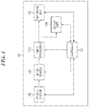
- FIG. 1 is a block diagram showing an entire image pickup apparatus concerning a first embodiment.
- FIG. 2 is a view describing a flow of an image process of the first embodiment by an image processor in FIG. 1 .
- FIG. 3 is an example of a UI screen displayed at a time of picking up an image of a waterfall.
- FIG. 4 is a flowchart showing a composite image generation process concerning the first embodiment.
- FIG. 5 is a view describing image composition executed in a step S 403 in FIG. 4 .
- FIG. 6A through FIG. 6D are views showing waterfall images corresponding to the respective composite images shown in FIG. 5 .
- FIG. 7A through FIG. 7F are graphs showing histograms of pixel values within a target region in FIG. 3 in the respective composite images shown in FIG. 5 .
- FIG. 8 is a graph showing standard deviations of the pixel values within the target region in FIG. 3 in the respective composite images shown in FIG. 5 .
- FIG. 9 is a graph showing difference absolute value sums of the pixel values within the target region in FIG. 3 in the respective composite images shown in FIG. 5 .
- FIG. 10 is a view describing a flow of an image process by an image processor of an image pickup apparatus concerning a second embodiment.
- FIG. 11 is a flowchart showing a composite image generation process concerning the second embodiment.
- FIG. 12 is a view describing image composition executed in a step S 1103 in FIG. 11 when an image pickup condition is “to pick up a high resolution image”.
- FIG. 13A through FIG. 13F are views describing feature amount calculation executed in a step S 1104 in FIG. 11 and determination executed in a step S 1105 when the image pickup condition is “to pick up a high resolution image”.
- FIG. 14A through FIG. 14D are graphs showing an example of image composition when an image pickup condition concerning a second embodiment is “to pick up an image having a wide dynamic range”.
- FIG. 1 is a block diagram showing an entire image pickup apparatus 101 concerning the first embodiment.
- the image pickup apparatus 101 is provided with an optical system 102 , an image sensor 103 , an image processor 104 , a recording unit 105 , a display unit 106 , and a controller 107 .
- the optical system 102 is provided with an optical diaphragm, a focus adjustment mechanism, a lens like a zoom lens, etc.
- the image sensor 103 is a photoelectric conversion element, such as a CCD or a CMOS, that converts an object image into an electrical signal and generates a pickup image. That is, the image sensor 103 is an image pickup unit that picks up an image of an object.
- the image processor 104 applies a developing process like a debayer process to the signal from the image sensor 103 and generates image data.
- the recording unit 105 stores image data.
- the display unit 106 displays image data, image pickup data, etc.
- the controller 107 controls the optical system 102 , image sensor 103 , image processor 104 , recording unit 105 , and display unit 106 .
- the image processor 104 is provided with an image composition unit 205 , a feature-amount calculation unit 206 , and a termination determination unit 207 as shown in FIG. 2 .
- the image processor 104 executes an image process that successively composites pickup images 202 that are input and generates a final composite image 203 .
- the controller 107 inputs information about the number of pickup images 204 into the image processor 104 .
- the information shows an order of a pickup image that is now input into the image processor 104 and is being composited.
- the image composition unit 205 generates a composite image of a series of pickup images whenever the image sensor 103 picks up an image of the object. Contents of the image composition of this embodiment will be mentioned later by referring to FIG. 5 through FIG. 9 .
- the feature-amount calculation unit 206 calculates a feature amount relevant to the composite image that the image processor 104 successively generates. It is not necessary to find the feature amount about the entire composite image. That is, the feature amount is calculated only about a place where a user wants to obtain a predetermined effect in the final composite image 203 .
- a UI screen 300 ( FIG. 3 ) is displayed on the display unit 106 when a user wants to obtain an effect that emphasizes a “flow” in a pickup image of a fluid object like a waterfall. After that, the user selects a place (a tartlet region 302 shown as a hatched area that is the center of the flow of the waterfall in the example of FIG.
- the feature-amount calculation unit 206 calculates the feature amount only from this tartlet region 302 in the composite image. It should be noted that the target region 302 that is the center of the flow of the waterfall may not be selected by the user. The target region 302 may be found by scene discrimination, motion detection, etc. Moreover, contents of the feature amount calculated by the feature-amount calculation unit 206 will be mentioned later.
- the termination determination unit 207 determines whether the feature amount satisfies a termination condition and whether the number of pickup images 204 reaches the maximum number of pickup images. Moreover, on the basis of the results of the determinations, the termination determination unit 207 determines whether the image composition by the image composition unit 205 is terminated and whether an additional image pickup operation is terminated. In this embodiment, when a user selects a flow effect (smoothness of a fluid object) from among “Large”, “Medium”, and “Small” in a message area 303 of the UI screen 300 shown in FIG. 3 , the controller 107 sets up a threshold corresponding to the selected flow effect.
- a flow effect smoothness of a fluid object
- the controller 107 also has a function as a determination unit that determines a termination condition according to the image pickup condition designated by the user. When the feature amount becomes less than this threshold, the termination determination unit 207 determines that the feature amount satisfies the termination condition. Then, the termination determination unit 207 outputs the final composite image 203 of which the feature amount satisfies the termination condition. That is, the termination determination unit 207 also has a function as an output unit that outputs the final composite image 203 . In addition, this termination condition may be beforehand defined by the controller 107 depending on the image pickup method.
- FIG. 4 is a flowchart showing a composite image generation process concerning the first embodiment. This process is executed when the controller 107 and the image processor 104 read programs that are beforehand held inside.
- the controller 107 first determines an image pickup condition, the number of pickup images, a feature amount, a termination condition, etc. in a step S 401 in FIG. 4 .
- the image pickup condition determined in this step is “to pick up an image having an effect that emphasizes a flow” that is used when picking up a waterfall image.
- the user determines the image pickup condition that is “to pick up an image having an effect that emphasizes a flow” when the UI screen 300 is displayed on the display unit 106 .
- operations such as obtainment of a plurality of appropriate exposure images and execution of average composition, of an image pickup process and a composition process are determined, for example.
- the target region 302 that is the center of the flow of the waterfall in the waterfall image 301 that is preview displayed on the UI screen 300 , the region in which the feature amount is calculated is determined.
- the controller 107 and display unit 106 function as an obtaining unit that obtains an image pickup condition of an object from a user. Furthermore, when the user designates the flow effect in the message area 303 of the UI screen 300 , the termination condition is determined according to the designated flow effect and the content of the feature amount set up beforehand.
- the number of pickup images determined in this step is an upper limit (the maximum number of pickup images) of the number of images that are subjected to the composition process. It should be noted that a feature amount is not limited to the feature amount exemplified hereinafter as long as a feature amount is able to express a “flow” of an image. Moreover, the termination condition may be a condition that is able to determine whether the effect of a “flow” is sufficient on the basis of the found feature amount.
- the controller 107 controls the optical system 102 and image sensor 103 to generate one pickup image in a step S 402 .
- the image processor 104 may add necessary processes (what is called development processes, such as a debayer process and a white balance process) to the process of the step S 402 so that the following composition process may become available.
- an image composition is performed in a step S 403 .
- the process of the step S 403 is performed when a second pickup image or later is generated in the immediately preceding step S 402 .
- the image composition will be described by referring to FIG. 5 using the case where the waterfall image 301 is picked up under the image pickup condition that is “to pick up an image having an effect that emphasizes a flow”.
- FIG. 5 schematically shows a state where the image pickup and the composition process progress sequentially from left toward right as shown by an arrow in an upper row. Details of processing time and timing are omitted.
- a first line in FIG. 5 shows pickup images f 1 through f 6 that are sequentially generated one by one in the step S 402 .
- the following line shows addition images that are sequentially added whenever one of the pickup images f 1 through f 6 is picked up. That is, when the second pickup image f 2 is picked up after picking up the first pickup image f 1 , an addition image f 1 +f 2 is generated by adding each pixel value of the first pickup image f 1 and a corresponding pixel value of the second pickup image f 2 .
- an addition image f 1 +f 2 +f 3 is generated
- an addition image f 1 +f 2 +f 3 +f 4 is generated.
- the following line shows composite images each of which is an average image that is calculated from a generated addition image and the number of pickup images up to the present, whenever the addition image is generated. That is, when the second pickup image f 2 is picked up and the addition image f 1 +f 2 is generated, an average image obtained by dividing the addition image f 1 +f 2 by the number of pickup images 2 becomes a composite image (f 1 +f 2 )/2. Similarly, when the third pickup image f 3 is picked up and the addition image f 1 +f 2 +f 3 is generated, a composite image (f 1 +f 2 +f 3 )/3 is calculated by dividing the addition image f 1 +f 2 +f 3 by 3.
- a composite image (f 1 +f 2 +f 3 +f 4 )/4 is calculated by dividing the addition image f 1 +f 2 +f 3 +f 4 by 4.
- FIG. 6A through FIG. 6D show the waterfall images in the composite images shown in FIG. 5 .
- FIG. 6A shows the pickup image f 1 generated by the first pickup, and the “flow” of the water surface of the waterfall 601 is little.
- FIG. 6B through FIG. 6D show the states where the pickup images f 1 through f 4 are composited sequentially and are equivalent to the composite images (f 1 +f 2 )/2, (f 1 +f 2 +f 3 )/3, and (f 1 +f 2 +f 3 +f 4 )/4 in FIG. 5 , respectively.
- a case where the composite image (f 1 +f 2 +f 3 +f 4 )/4 in FIG. 5 has a sufficient effect of the “flow” of the waterfall will be described.
- the feature amount of the composite image generated in the immediately preceding step S 403 will be calculated in a step S 404 .
- the feature amount of the composite image is determined in the step S 401 according to an object and a result.
- This embodiment describes the feature amount of the composite image in the case where the “flow” effect is given in the target region 302 in FIG. 3 that is determined as a region where the feature amount is calculated in the step S 401 .
- FIG. 7A through FIG. 7D are graphs showing histograms of pixel values within the target region in FIG. 3 in the respective composite images shown in FIG. 5 .
- a horizontal axis shows a pixel value
- a vertical axis shows a frequency of each pixel value.
- FIG. 7A is a histogram that is found about the first pickup image f 1
- FIG. 7B is a histogram that is found about the composite image (f 1 +f 2 )/2
- FIG. 7C is a histogram that is found about the composite image (f 1 +f 2 +f 3 )/3
- the termination determination unit (output unit) 207 determines that the termination condition is satisfied in a case where the variation of the histogram of the composite image becomes less than a first threshold.
- a difference value between a frequency of the histogram of the previously-generated composite image and a frequency of the histogram of the newly-generated composite image is calculated for every pixel value.
- the shape variation of the histogram is found by calculating a total sum of a square of the difference value. That is, the shape change ⁇ H of the histogram is found by the following formula using a frequency xi of the histogram of the previously-generated composite image of a certain pixel value i and a frequency yi of the histogram of the newly-generated composite image of the certain pixel value i.
- the shape change ⁇ H may be used as the feature amount.
- the cross correlation function value may be used as the feature amount.
- the cross correlation function value approaches 1.0 as the shape variation of the histogram becomes small.
- FIG. 8 shows the standard deviation of the pixel values in the target region 302 in FIG. 3 in each composite image shown in FIG. 5 .
- a horizontal axis shows the number of composite images (the number of pickup images) and a vertical axis shows the standard deviation of the composite image.
- the variation of the standard deviation becomes small as the number of composite image increases. That is, the “flow” effect approaches the certain effect, and the variation becomes small. Accordingly, the variation of the standard deviation can also be used as the feature amount.
- the termination determination unit (output unit) 207 determines that the termination condition is satisfied in a case where the variation of the standard deviation of the composite image becomes less than a second threshold.
- correlation between the adjacent composite images may be used as the feature amount.
- a difference absolute value sum of the composite image at the time when the number of pickup images is three and the composite image at the time when the number of pickup images is two is found as the correlation of the adjacent composite images at the time when the number of pickup images is three.
- FIG. 9 shows the difference absolute value sum of the pixel values in the target region 302 in FIG. 3 in each composite image shown in FIG. 5 .
- the difference absolute value sum becomes small as the number of composited pickup images increases. That is, the “flow” effect approaches the certain effect, and the variation becomes small. Accordingly, the variation of the difference absolute value sum can also be used as the feature amount.
- the termination determination unit (output unit) 207 determines that the termination condition is satisfied in a case where the variation of the difference absolute value sum of the composite image becomes less than a third threshold.
- the histogram, dispersion, standard deviation, and difference absolute value sum are exemplified as the feature amount, a combination of them can also be used as the feature amount.
- step S 405 it is determined whether the feature amount of the composite image calculated in the step S 404 satisfies the termination condition (whether the feature amount is less than a threshold) in a step S 405 . That is, when it is determined that the composite image has the effect required by the user on the basis of the feature amount calculated in the step S 404 , for example, when it is determined that a condition that the “flow” effect of the waterfall image in the composite image is large is sufficiently satisfied, the image pickup operation is stopped, and the process proceeds to a step S 407 . In the step S 407 , the final composite image is output (is displayed on the display unit 106 or is record into the recording unit 105 ), and this process is finished.
- the feature amount is the histogram
- the feature amount is the standard deviation
- the shape variation of the standard deviation is less than the threshold that is the termination condition determined in the step S 401
- the image pickup operation is stopped.
- the feature amount is the difference absolute value sum
- the shape variation of the difference absolute value sum is less than the threshold that is the termination condition determined in the step S 401
- the difference absolute value sum is less than a threshold th shown in FIG.
- step S 405 when it is determined that the feature amount of the composite image calculated in the step S 404 does not satisfy the termination condition (the feature amount is more than the threshold), the process proceeds to a step S 406 .
- the step S 406 when the number of pickup images determined does not reach the maximum number of pickup images determined in the step S 401 , the process returns to the step S 402 and the image pickup operation is repeated.
- the image pickup operation stops, the process proceeds to the step S 407 , the final composite image is output, and this process is finished.
- the feature amount and the final output image will be described.
- the feature amount of the composite image is calculated. For example, when the second pickup image f 2 is generated and the composite image (f 1 +f 2 )/2 is generated, the feature amount a 2 is found about the composite image (f 1 +f 2 )/2.
- the feature amount a 2 shall not satisfy the termination condition (the effect required by a user for the composite image shall be insufficient) because the feature amount a 2 is more than the threshold.
- the following third pickup image f 3 is generated and the composite image (f 1 +f 2 +f 3 )/3 is generated, and the feature amount a 3 is found about the composite image (f 1 +f 2 +f 3 )/3.
- the feature amount a 3 shall not satisfy the termination condition because the feature amount a 3 is more than the threshold.
- the following fourth pickup image f 4 is generated and the composite image (f 1 +f 2 +f 3 +f 4 )/4 is generated, and the feature amount a 4 is found about the composite image (f 1 +f 2 +f 3 +f 4 )/4.
- the feature amount a 4 shall satisfy the termination condition because the feature amount a 4 is less than the threshold.
- the image pickup operations to generate the fifth pickup image f 5 and sixth pickup image f 6 stop and no composite image is generated. That is, in this embodiment, the final composite image that is output in the step S 407 is the composite image (f 1 +f 2 +f 3 +f 4 )/4 generated when the fourth pickup image f 4 is generated.
- the present invention merely requires not to generate a new composite image after the feature amount calculated in the step S 404 satisfies the termination condition, and it is not necessary to stop a subsequent image pickup operation.
- composite images are generated successively while picking up images and when the feature amount of the generated composite image satisfies the termination condition, the composite image is output as the final composite image in this embodiment. Accordingly, a composite image having a sufficient effect required by a user is obtained without considering the required number of pickup images by the user.
- the second embodiment is different from the first embodiment in a point of considering an image pickup condition at a time of generation of a composite image.
- the entire configuration of the second embodiment is the same as that of the first embodiment. Accordingly, a configuration that is the same as that of the first embodiment is denoted by the same reference number and an overlapped description is omitted.
- FIG. 10 is a view describing a flow of an image process executed by an image processor 104 of the image pickup apparatus concerning the second embodiment.
- the image processor 104 is provided with an image composition unit 1006 , a feature-amount calculation unit 1007 , and a termination determination unit 1008 as shown in FIG. 10 .
- the image processor 104 executes an image process that successively composites pickup images 1002 that are input and generates a final composite image 1004 .
- the controller 107 inputs information about the number of pickup images 1003 into the image processor 104 .
- the information shows an order of a pickup image that is now input into the image processor 104 and is being composited.
- the controller 107 inputs information about the exposure conditions 1005 , such as exposure time, an aperture value, and a value of ISO, that are set corresponding to the image pickup condition into the image processor 104 .
- the image composition unit 1006 performs image composition of pickup images considering the image pickup condition. Contents of the image composition of this embodiment will be mentioned later by referring to FIG. 12 through FIG. 14 .
- the feature-amount calculation unit 1007 calculates a feature amount relevant to the composite image that the image processor 104 successively generates. As with the first embodiment, it is not necessary to find the feature amount about the entire composite image. That is, the feature amount is calculated only about a place where a user wants to obtain a predetermined effect in the final composite image 1004 . Also, in this embodiment, the feature amount is calculated about the target region 302 that is the center of the flow of the waterfall in FIG. 3 as with the first embodiment. Contents of the feature amount will be mentioned later.
- the termination determination unit 1008 determines whether the feature amount satisfies a termination condition and whether the number of pickup images 1003 reaches the maximum number of pickup images. Moreover, on the basis of the results of the determinations, the termination determination unit 1007 determines whether the image composition by the image composition unit 1006 is terminated and whether an additional image pickup operation is terminated.
- FIG. 11 An example of the image composition in a case where the image pickup condition is “to pick up a high resolution image” will be described first using FIG. 11 , FIG. 12 , and FIG. 13A through FIG. 13F .
- FIG. 11 is a flowchart showing a composite image generation process concerning the second embodiment. As with the flowchart of FIG. 4 , this process is executed when the controller 107 and the image processor 104 read programs that are beforehand held inside.
- FIG. 12 shows pickup images, composite images, feature amounts of the composite images, and a final composite image from the top. Whenever the pickup images f 1 through f 6 are picked up, the composite images are generated successively and the feature amounts b 2 through b 4 of the composite images are calculated. When it is determined that the calculated feature amount satisfies the termination condition (the effect required by a user is sufficient), the image pickup operation stops, and the final composite image is output.
- FIG. 12 shows an example where pixel values of the pickup images f 1 , 12 , and f 3 is added simply to generate the third composite image, the pixel values may be weighed according to the image pickup condition actually.
- the feature amount of the composite image generated in the step S 1103 will be calculated according to the image pickup condition in a step S 1104 . After that, it is determined whether the feature amount of the composite image calculated in the step S 1104 satisfies the termination condition in a step S 1105 .
- the feature amount of the composite image is the maximum pixel value in the target region.
- the maximum pixel value reaches an upper limit pixel value that a composite image is expressible (when the feature amount exceeds the threshold)
- the upper limit pixel value that a composite image is expressible is 255. Accordingly, when the maximum value of the pixel value in the target region reaches 255, it is determined that the feature amount satisfies the termination condition. This state is described using FIG. 13A through FIG. 13F .
- FIG. 13F are graphs that show histograms of the pixel values in the target region 302 of the respective composite images shown in FIG. 12 .
- a horizontal axis shows a pixel value
- a vertical axis shows a frequency.
- an upward white arrow indicates the maximum pixel value (feature amount) in the target region 302 of the composite image.
- a downward black triangle indicates the upper limit pixel value (threshold) that a composite image is expressible.
- the maximum pixel value in the target region 302 is found as a feature amount. When the found feature amount does not reach the upper limit pixel value that a composite image is expressible, an image pickup operation is repeated.
- the exposure value at the time of picking up an image may be adjusted using the upper limit pixel value that a composite image is expressible so that the maximum pixel value of the composite image will not exceed 255.
- step S 1105 when the feature amount satisfies the termination condition in the step S 1105 , it is determined that the image having the maximum pixel value that the user requires has been obtained, the image pickup operation is stopped, and the process proceeds to a step S 1107 .
- the process proceeds to a step S 1106 .
- step S 1106 after performing the same determination as the step S 406 , the process proceeds to the step S 1102 or the step S 1107 .
- the final composite image is output in the step S 1107 like the step S 407 in FIG. 4 , and this process is finished.
- a width of a dynamic range that a user requires is determined as a threshold used as a termination condition in the step S 1101 .
- the same process as the step S 402 in FIG. 4 is performed in the step S 1102 .
- an image pickup operation is performed under a condition where an exposure value is increased by a certain amount from the previous image pickup operation according to the exposure condition 1005 .
- the image composition that considers the image pickup condition determined in the step S 1101 is performed in the step S 1103 . That is, the image composition unit 205 generates the composite image by adding a series of every image of the object that is picked up by the image sensor 103 under the different exposure conditions.
- FIG. 14A through FIG. 14C show histograms of pixel values in the target region 302 shown in FIG. 3 in the pickup images obtained while increasing the exposure value in the order.
- the histogram essentially includes two peaks, only one peak is observed in the histogram exemplified in FIG. 14C because the pickup image is saturated due to overexposure.
- the composite image is generated by converting the pixel values of the pickup images so that the exposures of the pickup images will be identical.
- FIG. 14D shows a histogram of the pixel values in the target region 302 shown in FIG. 3 in this composite image.
- a high luminance part is composited preponderantly using the pixel values of the first pickup image of which the histogram is shown in FIG. 14A .
- a medium luminance part is composited preponderantly using the pixel values of the second pickup image of which the histogram is shown in FIG. 14B .
- a low luminance part is composited preponderantly using the pixel values of the third pickup image of which the histogram is shown in FIG. 14C .
- the composite image of which a dynamic range is larger than that of one pickup image can be obtained.
- a width of the dynamic range is calculated as a feature amount using the histogram of FIG. 14D in the step S 1104 .
- the width (feature amount) of the dynamic range calculated in the step S 1105 reaches the threshold set in the step S 1101 , it is determined that the image having the dynamic range of which the width is required by the user is obtained, the image pickup operation is stopped, and the process proceeds to the step S 1107 . In the meantime, when the feature amount does not reach the threshold, it is determined that the image having the dynamic range of which the width is required by the user is not obtained, the process returns to the step S 1102 , and a new image pickup operation is performed while increasing the exposure value by the certain amount from the exposure value of the previous image pickup operation.
- composite images are generated successively by picking up images considering the image pickup condition in this embodiment. And when the feature amount of the generated composite image satisfies the termination condition, the composite image is output as the final composite image. Accordingly, a composite image having a sufficient effect required by a user is obtained without considering the required number of pickup images by the user.
- the present invention may be used for starlit sky photography etc.
- pre-processes like alignment etc. are necessary.
- the present invention includes a case where a composite image is generated in order to obtain an object or an effect other than the image pickup conditions exemplified in the first and second embodiments.
- a threshold that becomes a termination condition, and a method for calculating a feature amount of a composite image are set up according to the object or the effect.
- an object or an effect is considered when a composite image is generated.
- Embodiment(s) of the present invention can also be realized by a computer of a system or apparatus that reads out and executes computer executable instructions (e.g., one or more programs) recorded on a storage medium (which may also be referred to more fully as a ‘non-transitory computer-readable storage medium’) to perform the functions of one or more of the above-described embodiment(s) and/or that includes one or more circuits (e.g., application specific integrated circuit (ASIC)) for performing the functions of one or more of the above-described embodiment(s), and by a method performed by the computer of the system or apparatus by, for example, reading out and executing the computer executable instructions from the storage medium to perform the functions of one or more of the above-described embodiment(s) and/or controlling the one or more circuits to perform the functions of one or more of the above-described embodiment(s).
- computer executable instructions e.g., one or more programs
- a storage medium which may also be referred to more fully as a
- the computer may comprise one or more processors (e.g., central processing unit (CPU), micro processing unit (MPU)) and may include a network of separate computers or separate processors to read out and execute the computer executable instructions.
- the computer executable instructions may be provided to the computer, for example, from a network or the storage medium.
- the storage medium may include, for example, one or more of a hard disk, a random-access memory (RAM), a read only memory (ROM), a storage of distributed computing systems, an optical disk (such as a compact disc (CD), digital versatile disc (DVD), or Blu-ray Disc (BD)TM), a flash memory device, a memory card, and the like.
Landscapes
- Engineering & Computer Science (AREA)
- Multimedia (AREA)
- Theoretical Computer Science (AREA)
- Signal Processing (AREA)
- Computer Vision & Pattern Recognition (AREA)
- Physics & Mathematics (AREA)
- General Physics & Mathematics (AREA)
- Artificial Intelligence (AREA)
- Health & Medical Sciences (AREA)
- Computing Systems (AREA)
- Databases & Information Systems (AREA)
- Evolutionary Computation (AREA)
- General Health & Medical Sciences (AREA)
- Medical Informatics (AREA)
- Software Systems (AREA)
- Studio Devices (AREA)
Abstract
Description
Claims (13)
Applications Claiming Priority (3)
| Application Number | Priority Date | Filing Date | Title |
|---|---|---|---|
| JPJP2020-018947 | 2020-02-06 | ||
| JP2020-018947 | 2020-02-06 | ||
| JP2020018947A JP7566470B2 (en) | 2020-02-06 | 2020-02-06 | Imaging device and control method |
Publications (2)
| Publication Number | Publication Date |
|---|---|
| US20210250493A1 US20210250493A1 (en) | 2021-08-12 |
| US11323613B2 true US11323613B2 (en) | 2022-05-03 |
Family
ID=77177843
Family Applications (1)
| Application Number | Title | Priority Date | Filing Date |
|---|---|---|---|
| US17/152,020 Active US11323613B2 (en) | 2020-02-06 | 2021-01-19 | Image pickup apparatus that composites images, control method therefor, and storage medium storing program for executing control method |
Country Status (2)
| Country | Link |
|---|---|
| US (1) | US11323613B2 (en) |
| JP (1) | JP7566470B2 (en) |
Citations (11)
| Publication number | Priority date | Publication date | Assignee | Title |
|---|---|---|---|---|
| US20100265357A1 (en) * | 2009-04-17 | 2010-10-21 | Sony Corporation | Generation of simulated long exposure images in response to multiple short exposures |
| JP2014171146A (en) | 2013-03-05 | 2014-09-18 | Canon Inc | Image pickup device |
| US20140313367A1 (en) * | 2013-04-18 | 2014-10-23 | Olympus Corporation | Imaging device and imaging method |
| US20140362258A1 (en) * | 2013-06-10 | 2014-12-11 | Olympus Corporation | Image processing apparatus, image processing method, and computer readable recording medium |
| US20160073011A1 (en) * | 2014-09-05 | 2016-03-10 | Canon Kabushiki Kaisha | Image capturing apparatus and control method therefor |
| US20160105596A1 (en) * | 2014-10-08 | 2016-04-14 | Olympus Corporation | Imaging device and shooting method |
| US20170134666A1 (en) * | 2014-07-02 | 2017-05-11 | Nubia Technology Co., Ltd. | Method and apparatus for shooting star trail video, and computer storage medium |
| US20170171474A1 (en) * | 2015-12-10 | 2017-06-15 | Olympus Corporation | Imaging device and imaging method |
| US20190122040A1 (en) * | 2016-04-29 | 2019-04-25 | Marss Ventures S.A. | Method of verifying a triggered alert and alert verification processing apparatus |
| US10359498B2 (en) * | 2016-03-15 | 2019-07-23 | Canon Kabushiki Kaisha | Image pickup apparatus having function of generating simulation image,control method therefor, and storage medium |
| US10701279B2 (en) * | 2018-10-02 | 2020-06-30 | Adobe Inc. | Utilizing alignment models and motion vector path blending to generate a long exposure digital image from a sequence of short exposure digital images |
Family Cites Families (8)
| Publication number | Priority date | Publication date | Assignee | Title |
|---|---|---|---|---|
| JP4942572B2 (en) * | 2007-07-13 | 2012-05-30 | 富士フイルム株式会社 | Image adding apparatus and method, and program |
| JP5163031B2 (en) * | 2007-09-26 | 2013-03-13 | 株式会社ニコン | Electronic camera |
| JP4655239B2 (en) * | 2008-09-24 | 2011-03-23 | ソニー株式会社 | Imaging apparatus, control method thereof, and program |
| JP2012119761A (en) * | 2010-11-29 | 2012-06-21 | Sanyo Electric Co Ltd | Electronic apparatus, image processing method and program |
| JP5784316B2 (en) * | 2011-01-31 | 2015-09-24 | オリンパス株式会社 | Valve imaging device and valve imaging method |
| JP2013118562A (en) * | 2011-12-05 | 2013-06-13 | Nikon Corp | Imaging apparatus |
| JP2017163191A (en) * | 2016-03-07 | 2017-09-14 | オリンパス株式会社 | Image processing apparatus, imaging apparatus, image processing method, and program |
| JP6879278B2 (en) * | 2018-09-27 | 2021-06-02 | 株式会社ニコン | Electronic equipment and control programs |
-
2020
- 2020-02-06 JP JP2020018947A patent/JP7566470B2/en active Active
-
2021
- 2021-01-19 US US17/152,020 patent/US11323613B2/en active Active
Patent Citations (15)
| Publication number | Priority date | Publication date | Assignee | Title |
|---|---|---|---|---|
| US8228400B2 (en) * | 2009-04-17 | 2012-07-24 | Sony Corporation | Generation of simulated long exposure images in response to multiple short exposures |
| US20100265357A1 (en) * | 2009-04-17 | 2010-10-21 | Sony Corporation | Generation of simulated long exposure images in response to multiple short exposures |
| JP2014171146A (en) | 2013-03-05 | 2014-09-18 | Canon Inc | Image pickup device |
| US20140313367A1 (en) * | 2013-04-18 | 2014-10-23 | Olympus Corporation | Imaging device and imaging method |
| US20140362258A1 (en) * | 2013-06-10 | 2014-12-11 | Olympus Corporation | Image processing apparatus, image processing method, and computer readable recording medium |
| US20170134666A1 (en) * | 2014-07-02 | 2017-05-11 | Nubia Technology Co., Ltd. | Method and apparatus for shooting star trail video, and computer storage medium |
| US10244184B2 (en) * | 2014-07-02 | 2019-03-26 | Nubia Technology Co., Ltd. | Method and apparatus for shooting star trail video, and computer storage medium |
| US20160073011A1 (en) * | 2014-09-05 | 2016-03-10 | Canon Kabushiki Kaisha | Image capturing apparatus and control method therefor |
| US20160105596A1 (en) * | 2014-10-08 | 2016-04-14 | Olympus Corporation | Imaging device and shooting method |
| US9936144B2 (en) | 2014-10-08 | 2018-04-03 | Olympus Corporation | Imaging device and shooting method capable of generating a bulb exposure image |
| JP2016076869A (en) | 2014-10-08 | 2016-05-12 | オリンパス株式会社 | Imaging apparatus, imaging method, and program |
| US20170171474A1 (en) * | 2015-12-10 | 2017-06-15 | Olympus Corporation | Imaging device and imaging method |
| US10359498B2 (en) * | 2016-03-15 | 2019-07-23 | Canon Kabushiki Kaisha | Image pickup apparatus having function of generating simulation image,control method therefor, and storage medium |
| US20190122040A1 (en) * | 2016-04-29 | 2019-04-25 | Marss Ventures S.A. | Method of verifying a triggered alert and alert verification processing apparatus |
| US10701279B2 (en) * | 2018-10-02 | 2020-06-30 | Adobe Inc. | Utilizing alignment models and motion vector path blending to generate a long exposure digital image from a sequence of short exposure digital images |
Also Published As
| Publication number | Publication date |
|---|---|
| US20210250493A1 (en) | 2021-08-12 |
| JP2021125820A (en) | 2021-08-30 |
| JP7566470B2 (en) | 2024-10-15 |
Similar Documents
| Publication | Publication Date | Title |
|---|---|---|
| US10194091B2 (en) | Image capturing apparatus, control method therefor, program, and recording medium | |
| US9531960B2 (en) | Imaging apparatus for generating HDR image from images captured at different viewpoints and method for controlling imaging apparatus | |
| JP6116272B2 (en) | Image processing apparatus, image processing method, program, and storage medium | |
| US11818466B2 (en) | Notifying apparatus, image capturing apparatus, notifying method, image capturing method, and storage medium | |
| US9313416B2 (en) | Image processing apparatus that performs gradation correction of photographed image, method of controlling the same, and storage medium | |
| US20150163391A1 (en) | Image capturing apparatus, control method of image capturing apparatus, and non-transitory computer readable storage medium | |
| US10708555B2 (en) | Image processing apparatus, image processing method, and storage medium | |
| US9699387B2 (en) | Image processing device for processing pupil-divided images obtained through different pupil regions of an imaging optical system, control method thereof, and program | |
| US11831991B2 (en) | Device, control method, and storage medium | |
| US11341622B2 (en) | Image processing apparatus, image capturing apparatus, image processing method, and storage medium | |
| JP6423668B2 (en) | Image processing apparatus, control method therefor, and program | |
| CN105763767B (en) | Image processing device, imaging device, and image processing method | |
| US11593925B2 (en) | Apparatus, method, and storage medium | |
| US10832386B2 (en) | Image processing apparatus, image processing method, and storage medium | |
| US9565412B2 (en) | Image processing apparatus that develops photographed data, image processing method, and recording medium | |
| US11323613B2 (en) | Image pickup apparatus that composites images, control method therefor, and storage medium storing program for executing control method | |
| US11057598B2 (en) | Image processing apparatus, image capturing apparatus, image processing method, and storage medium | |
| US12526527B2 (en) | Imaging device, method for controlling imaging device and non-transitory computer-readable storage medium with improving brightness through gradation correction | |
| JP6075829B2 (en) | IMAGING DEVICE, CAMERA SYSTEM, IMAGING DEVICE CONTROL METHOD, PROGRAM, AND STORAGE MEDIUM | |
| US10027881B2 (en) | Image processing apparatus, image processing method, and storage medium | |
| US20240137657A1 (en) | Imaging apparatus | |
| US20250287094A1 (en) | Information processing apparatus that notifies subject blur, image capturing apparatus, information processing method, and control method | |
| US20230370725A1 (en) | Imaging apparatus and control method for imaging apparatus | |
| US20240163568A1 (en) | Image capturing apparatus that generates images that can be depth-combined, method of controlling same, and storage medium |
Legal Events
| Date | Code | Title | Description |
|---|---|---|---|
| FEPP | Fee payment procedure |
Free format text: ENTITY STATUS SET TO UNDISCOUNTED (ORIGINAL EVENT CODE: BIG.); ENTITY STATUS OF PATENT OWNER: LARGE ENTITY |
|
| AS | Assignment |
Owner name: CANON KABUSHIKI KAISHA, JAPAN Free format text: ASSIGNMENT OF ASSIGNORS INTEREST;ASSIGNOR:MAKINO, JUN;REEL/FRAME:055188/0393 Effective date: 20210108 |
|
| STPP | Information on status: patent application and granting procedure in general |
Free format text: APPLICATION DISPATCHED FROM PREEXAM, NOT YET DOCKETED |
|
| STPP | Information on status: patent application and granting procedure in general |
Free format text: DOCKETED NEW CASE - READY FOR EXAMINATION |
|
| STPP | Information on status: patent application and granting procedure in general |
Free format text: NOTICE OF ALLOWANCE MAILED -- APPLICATION RECEIVED IN OFFICE OF PUBLICATIONS |
|
| STPP | Information on status: patent application and granting procedure in general |
Free format text: AWAITING TC RESP., ISSUE FEE NOT PAID |
|
| STPP | Information on status: patent application and granting procedure in general |
Free format text: NOTICE OF ALLOWANCE MAILED -- APPLICATION RECEIVED IN OFFICE OF PUBLICATIONS |
|
| STPP | Information on status: patent application and granting procedure in general |
Free format text: PUBLICATIONS -- ISSUE FEE PAYMENT VERIFIED |
|
| STCF | Information on status: patent grant |
Free format text: PATENTED CASE |
|
| MAFP | Maintenance fee payment |
Free format text: PAYMENT OF MAINTENANCE FEE, 4TH YEAR, LARGE ENTITY (ORIGINAL EVENT CODE: M1551); ENTITY STATUS OF PATENT OWNER: LARGE ENTITY Year of fee payment: 4 |