US11316748B2 - Method and system for generating and managing virtual industrial devices in an industrial network - Google Patents
Method and system for generating and managing virtual industrial devices in an industrial network Download PDFInfo
- Publication number
- US11316748B2 US11316748B2 US16/453,334 US201916453334A US11316748B2 US 11316748 B2 US11316748 B2 US 11316748B2 US 201916453334 A US201916453334 A US 201916453334A US 11316748 B2 US11316748 B2 US 11316748B2
- Authority
- US
- United States
- Prior art keywords
- industrial
- virtual
- processor
- devices
- communication
- Prior art date
- Legal status (The legal status is an assumption and is not a legal conclusion. Google has not performed a legal analysis and makes no representation as to the accuracy of the status listed.)
- Active
Links
Images


Classifications
-
- G—PHYSICS
- G06—COMPUTING OR CALCULATING; COUNTING
- G06F—ELECTRIC DIGITAL DATA PROCESSING
- G06F11/00—Error detection; Error correction; Monitoring
- G06F11/36—Prevention of errors by analysis, debugging or testing of software
- G06F11/362—Debugging of software
- G06F11/3648—Debugging of software using additional hardware
- G06F11/3652—Debugging of software using additional hardware in-circuit-emulation [ICE] arrangements
-
- H—ELECTRICITY
- H04—ELECTRIC COMMUNICATION TECHNIQUE
- H04L—TRANSMISSION OF DIGITAL INFORMATION, e.g. TELEGRAPHIC COMMUNICATION
- H04L41/00—Arrangements for maintenance, administration or management of data switching networks, e.g. of packet switching networks
- H04L41/14—Network analysis or design
- H04L41/145—Network analysis or design involving simulating, designing, planning or modelling of a network
-
- H—ELECTRICITY
- H04—ELECTRIC COMMUNICATION TECHNIQUE
- H04L—TRANSMISSION OF DIGITAL INFORMATION, e.g. TELEGRAPHIC COMMUNICATION
- H04L41/00—Arrangements for maintenance, administration or management of data switching networks, e.g. of packet switching networks
- H04L41/04—Network management architectures or arrangements
-
- H—ELECTRICITY
- H04—ELECTRIC COMMUNICATION TECHNIQUE
- H04L—TRANSMISSION OF DIGITAL INFORMATION, e.g. TELEGRAPHIC COMMUNICATION
- H04L41/00—Arrangements for maintenance, administration or management of data switching networks, e.g. of packet switching networks
- H04L41/06—Management of faults, events, alarms or notifications
- H04L41/0631—Management of faults, events, alarms or notifications using root cause analysis; using analysis of correlation between notifications, alarms or events based on decision criteria, e.g. hierarchy, tree or time analysis
-
- H—ELECTRICITY
- H04—ELECTRIC COMMUNICATION TECHNIQUE
- H04L—TRANSMISSION OF DIGITAL INFORMATION, e.g. TELEGRAPHIC COMMUNICATION
- H04L41/00—Arrangements for maintenance, administration or management of data switching networks, e.g. of packet switching networks
- H04L41/08—Configuration management of networks or network elements
- H04L41/0803—Configuration setting
- H04L41/084—Configuration by using pre-existing information, e.g. using templates or copying from other elements
- H04L41/0846—Configuration by using pre-existing information, e.g. using templates or copying from other elements based on copy from other elements
-
- H—ELECTRICITY
- H04—ELECTRIC COMMUNICATION TECHNIQUE
- H04L—TRANSMISSION OF DIGITAL INFORMATION, e.g. TELEGRAPHIC COMMUNICATION
- H04L43/00—Arrangements for monitoring or testing data switching networks
- H04L43/04—Processing captured monitoring data, e.g. for logfile generation
-
- H—ELECTRICITY
- H04—ELECTRIC COMMUNICATION TECHNIQUE
- H04L—TRANSMISSION OF DIGITAL INFORMATION, e.g. TELEGRAPHIC COMMUNICATION
- H04L43/00—Arrangements for monitoring or testing data switching networks
- H04L43/08—Monitoring or testing based on specific metrics, e.g. QoS, energy consumption or environmental parameters
-
- H—ELECTRICITY
- H04—ELECTRIC COMMUNICATION TECHNIQUE
- H04L—TRANSMISSION OF DIGITAL INFORMATION, e.g. TELEGRAPHIC COMMUNICATION
- H04L67/00—Network arrangements or protocols for supporting network services or applications
- H04L67/14—Session management
- H04L67/141—Setup of application sessions
-
- H—ELECTRICITY
- H04—ELECTRIC COMMUNICATION TECHNIQUE
- H04L—TRANSMISSION OF DIGITAL INFORMATION, e.g. TELEGRAPHIC COMMUNICATION
- H04L69/00—Network arrangements, protocols or services independent of the application payload and not provided for in the other groups of this subclass
- H04L69/22—Parsing or analysis of headers
-
- H—ELECTRICITY
- H04—ELECTRIC COMMUNICATION TECHNIQUE
- H04L—TRANSMISSION OF DIGITAL INFORMATION, e.g. TELEGRAPHIC COMMUNICATION
- H04L41/00—Arrangements for maintenance, administration or management of data switching networks, e.g. of packet switching networks
- H04L41/22—Arrangements for maintenance, administration or management of data switching networks, e.g. of packet switching networks comprising specially adapted graphical user interfaces [GUI]
Definitions
- the present embodiments relate to a field of testing environment, and more particularly, relates to a method and system for generating and managing virtual industrial devices in an industrial network.
- testing of functionally complex systems involves a set of activities such as test planning, system analysis, creation of test cases, execution of test cycles, and final testing.
- testing activities typically occur before a system is implemented into a target environment.
- the goal of system testing is to determine if a system meets the requirements that guided design and development of the system, works as expected, and may be implemented in a target environment with the desired functionality.
- System tests are usually referred as black box tests of a fully integrated system made up of software, controlled hardware, and a technical process. These tests include manual manipulations of the actual hardware or technical process that may not be performed by the software.
- Many steps currently performed in system testing require a testing operator to stimulate the system and validate behavior of the system.
- industrial automation scale and structure complexity of these systems, specialized non-functional requirements, and hardware-related issues make validation of these systems even more challenging and costly.
- test infrastructure One of the major hardware-related challenges during software testing is the availability of test infrastructure.
- the availability of test infrastructure is a major factor in development project costs. Effective system testing requires that the system under test runs in an environment as alike as possible to a production site.
- hardware is not even available in early product development life cycle, which makes hardware inaccessible to software developers. As a consequence, access to hardware for each software developer and software tester is limited.
- Another important hardware-related challenge during software testing is hardware fault conditions. With a large amount of hardware units in industrial systems, it is important to consider the hardware failures for each of these hardware units. However, it becomes difficult to generate specific hardware fault conditions or to generate anomaly loads in real time for these hardware units.
- a method and system for generating and managing virtual industrial devices in an industrial network are disclosed.
- a method for generating and managing one or more virtual industrial devices in an industrial network includes capturing data packets associated with an ongoing industrial communication in the industrial network between an industrial application and an industrial device.
- the industrial device includes industrial controlling/monitoring devices.
- the industrial devices include field devices, controllers, or the like.
- the industrial application includes automation engineering application.
- the method further the method includes segregating the captured data packets into one or more requests and corresponding one or more responses by analyzing information included in the data packets.
- the request includes a request header including one or more parameters.
- the response includes a response header corresponding to the request header and a device data.
- the information included in the data packets includes type of data packet, type of request, source address, destination address, port number, protocol identifier (ID), length of header, length of user data, sequence number, session identifier (ID), index, and one or more parameters associated with the data packets.
- the method also includes storing the one or more requests along with the one or more responses for the ongoing industrial communication in a memory.
- the method also includes dynamically generating one or more virtual industrial devices emulating the industrial device based on the stored one or more requests and the stored one or more responses. Additionally, the method includes establishing a communication session between the one or more generated virtual industrial devices and the industrial application for performing one or more test operations on the one or more generated virtual industrial devices.
- the one or more test operations include generating faults for the industrial device, testing one or more scenarios for the industrial device, and controlling parameters associated with the industrial device.
- the method includes obtaining device configuration information associated with the industrial device from the one or more requests and the one or more responses. Further, the method includes dynamically generating the one or more virtual industrial devices to emulate as the industrial device based on the obtained device configuration information.
- the method includes generating a communication library for storing the one or more requests along with the one or more responses in the memory.
- the communication library stores the one or more requests along with the one or more responses for each industrial device in communication with the industrial application.
- the method includes identifying a port number in the request for establishing communication with the industrial application. Further, the method includes determining whether the ongoing industrial communication between the industrial device and the industrial application is complete. Also, the method includes establishing the communication session between the one or more generated virtual industrial devices and the industrial application when the ongoing industrial communication between the industrial device and the industrial application is complete.
- the method includes terminating the ongoing industrial communication between the industrial device and the industrial application before establishing the communication session between the one or more generated virtual industrial devices and the industrial application.
- the method further includes determining whether a request is received from the industrial application.
- the request is received on a specific port number and the request includes one or more parameters.
- the method further includes determining whether the received request matches with at least one pre-stored requests based on the one or more parameters included in the received request. Further, the method includes retrieving the matched pre-stored request along with the corresponding pre-stored response for the received request from a memory. Further, the method includes identifying one or more modified parameters in the received request by comparing the one or more parameters in the received request with the one or more parameters in the matched pre-stored request.
- the one or more modified parameters includes an activity identifier, a session identifier, the port number, a sequence number, a protocol name, a protocol ID, type of request, data length, and index.
- the method also includes generating a response for the received request by modifying the pre-stored response based on the identified one or more modified parameters. Additionally, the method includes transmitting the generated response to the industrial application via the industrial network, where the response is transmitted via the specific port number.
- the method includes storing the received request in the memory if the received request fails to match with the at least one pre-stored requests and outputting a notification on a user interface.
- the notification indicates that the received request is stored in the memory.
- the notification may be in the form of an email message, an alert window, signal information, a text message, and the like.
- the method includes modifying the pre-stored response based on user-defined parameters and the identified one or more modified parameters.
- the method also includes generating the response for the received request.
- the response includes one or more modified parameters and the user-defined parameters.
- the user-defined parameters include one or more parameters associated with device data present in the pre-stored response.
- a method for managing one or more virtual industrial devices in an industrial network includes receiving a response from a virtual industrial device via the industrial network. Further, the method includes analyzing one or more parameters included in the response. The method further includes modifying information associated with the virtual industrial device based on the analyzed one or more parameters. Further, the method includes displaying the modified information associated with the virtual industrial device on a user interface.
- an apparatus for generating and managing one or more virtual industrial devices in an industrial network includes a processor and a memory coupled to the processor.
- the memory includes a virtual industrial device management module stored in the form of machine-readable instructions executable by the processor.
- the virtual industrial device management module is capable of performing the method acts described above.
- a computer-program product having machine-readable instructions stored therein.
- the machine-readable instructions when executed by the processor, causes the processor to perform method acts as described above is disclosed.
- an engineering system for managing virtual industrial devices in an industrial network includes a memory and a processor coupled to the memory.
- the processor executes programmed instructions stored in the memory (e.g., to perform method acts as described above).
- an industrial communication system for generating and managing virtual industrial devices in an industrial network.
- the industrial communication system includes an apparatus capable of generating and managing virtual industrial devices in an industrial network, an engineering system for managing the virtual industrial devices in the industrial network, and an industrial device communicatively coupled to the engineering system for managing the virtual industrial devices in the industrial network.
- a non-transitory computer-readable storage medium having machine-readable instructions stored therein.
- the machine-readable instructions when executed by at least one processor, cause the processor to perform the method acts described above.
- FIG. 1 is a schematic representation of an industrial communication system capable of generating and managing virtual industrial devices in an industrial network, according to an embodiment
- FIG. 2 is a schematic representation of a plant simulation diagram in a test environment, according to the embodiment
- FIG. 3 is a block diagram of a testing system, such as those in shown in FIG. 1 , showing various components to implement embodiments;
- FIG. 4 is a detailed view of a virtual industrial device management module such as those shown in FIG. 1 , according to the embodiment;
- FIG. 5 is a process flowchart illustrating an exemplary method of generating and managing virtual industrial devices in an industrial network, according to the embodiment
- FIG. 6 is a process flowchart illustrating an exemplary method of establishing a communication session between generated virtual industrial devices and industrial application for performing the one or more test operations on the generated virtual industrial devices, according to the embodiment;
- FIG. 7 is a process flowchart illustrating an exemplary method of generating and managing virtual industrial devices in an industrial network, according to another embodiment
- FIG. 8 is a block diagram of an engineering system, such as those shown in FIG. 1 , showing various components to implement embodiments of the present disclosure
- FIG. 9 is a process flowchart illustrating an exemplary method of managing virtual industrial devices in an industrial network, according to an embodiment
- FIGS. 10A-B show a screenshot view of a graphical user interface of a testing system that enables a user to generate and manage the virtual industrial devices in the industrial network;
- FIGS. 11A-B show a screenshot view of a graphical user interface of an engineering system that enables a user to manage virtual industrial devices in the industrial network.
- FIG. 1 is a schematic representation of an industrial communication system 100 capable of generating and managing virtual industrial devices 116 A-N in an industrial network, according to an embodiment of the present disclosure.
- the industrial communication system 100 includes a testing system 102 , an engineering system 104 , and an actual industrial device 108 .
- the engineering system 104 communicates with the actual industrial device 108 and the testing system 102 via an industrial network 106 .
- the testing system 102 may be any computing systems known in the art for implementing a virtual test environment 110 .
- the testing system 102 may be dedicated testing systems or general purpose computing devices such as industrial automation systems.
- the testing system 102 may be a part of an engineering system, such as the engineering system 104 including the virtual test environment 110 for generating and managing the virtual industrial devices 116 A-N. This may be achieved by using loopback addresses for PROFINET communication and a null emulator for serial communication.
- the virtual test environment 110 thus does not require any external hardware and is quicker than conventional mechanisms.
- the virtual test environment 110 enables automatically verifying behavior of the actual industrial device 108 without communicating with the actual industrial device 108 .
- the virtual test environment 110 enables the user to detect the status of the actual industrial device 108 in the industrial network 106 .
- the terms “actual industrial device 108 ” and “the industrial device 108 ” are used interchangeably throughout the specification.
- the components of the testing system 102 are further explained in FIG. 3 .
- the virtual test environment 110 includes a virtual industrial device management module 112 for generating and managing the virtual industrial devices 116 A-N.
- the virtual industrial device management module 112 is stored in the form of machine-readable instructions and executable by the testing system 102 through the virtual test environment 110 .
- the one or more virtual industrial devices 116 A-N replace the actual industrial device 108 and is configured for communicating with the industrial application 114 through a fixed port number.
- the one or more virtual industrial devices 116 A-N enable the user to change one or more parameters associated with the actual industrial device 108 and generate relevant test scenarios for the actual industrial device 108 .
- the engineering system 104 includes an industrial application 114 for representing engineered devices or other objects and to perform one or more control operations over the engineered devices or other objects.
- the engineering system 104 is any general-purpose computer capable of implementing the industrial application 114 .
- the industrial application 114 may be an automation engineering application, such as a total integrated automation (TIA) portal or any other known automation engineering application.
- the industrial application 114 enables a user to run a plurality of test scenarios for the industrial device 108 .
- the industrial application 114 also enables the user to generate specific hardware faults for the industrial device 108 without actually communicating with the industrial device 108 . This is done by using the virtual industrial devices 116 A-N.
- the industrial application 114 uses the virtual test environment 110 for monitoring the industrial device 108 to detect intrusion, behavior of the industrial device 108 , safety and performance of the industrial network 106 , and act as a load generator to observe the behavior of the industrial device 108 in the industrial network 106 .
- the actual industrial device 108 may be an industrial controlling or monitoring devices, such as, for example, SIMOCODE.
- the actual industrial device 108 may include an industrial field device.
- the industrial field device may be a converter, a motor starter, and an input/output module, or an actuator.
- the industrial field device may transmit field data (e.g., measurement data) to the industrial application 114 .
- the field data transmitted from the field devices to the central control unit may include measurement data of physical quantities.
- the field data may also describe a state of at least one of the field devices (e.g., the field data may also include a current value of an algorithm-parameter or a mode identity value describing the mode that a field device is currently running in).
- Another example of a field device is a sensor device.
- the actual industrial device 108 is an industrial controlling or monitoring device configured for communicating the field data associated with one or more field devices to the industrial application 114 in response to a request received from the industrial application 114 .
- the communication between the industrial device 108 and the industrial application 114 takes place via a fixed port number.
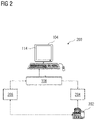
- FIG. 2 is a schematic representation of a plant simulation diagram 200 in a test environment, according to an embodiment of the present disclosure. Specifically, FIG. 2 describes communication between the field device 202 and the engineering system 104 via the industrial device 108 .
- the field device 202 is communicatively coupled to the industrial device 108 for exchanging information associated with the field device 202 and enabling the industrial device 108 to control the field device 202 via an actuator 204 .
- the information associated with the field device 202 may include field parameters. These field parameters are read by the industrial device 108 through sensors 206 . Upon obtaining the field parameters, the industrial device 108 communicates these field parameters to the industrial application 114 running on the engineering system 104 .
- the industrial device 108 communicates with the engineering system 104 via a communication protocol such as, for example, PROFINET, PROFIBUS and SERIAL communication.
- the industrial device 108 stores the information associated with the field device 202 in a particular memory location of fixed data length (e.g., data sets). Information stored in the respective data sets in form of Byte/Bit is according to the fixed data length. For example, if a user at the industrial application 114 wishes to view the information stored at the industrial device 108 , a particular data set corresponding to the information stored may be read. For example, data set 92 stores diagnostic information in the industrial device 108 .
- the industrial device 108 determines a value of the requested particular data set information from the captured request and response data packets.
- the industrial device 108 retrieves the corresponding information associated with the requested data set and correspondingly responds back to the industrial application 114 with the retrieved corresponding information.
- Data set information is fixed in each data packet.
- industrial communication between the industrial device 108 and the industrial application 114 may include, but is not limited to, either SERIAL communication, or PROFINET or PROFIBUS communication.
- the data packet exchanged between the industrial device 108 and the industrial application 114 during basic SERIAL communication includes length of data packet, length of user data, data set information, and a check sum bit.
- data packet exchanged between the industrial device 108 and the industrial application 114 during PROFINET communication includes information such as MAC address of source and destination terminals, IP addresses and the like.
- Detailed content of the data packet for SERIAL communication and PROFINET communication is known to a person skilled in the art.
- the request data packet and the response data packet may include almost same information except few parameters like request data type and the response data packet including additional device data associated with the field device 202 . Further, the industrial device 108 always communicates with the industrial application 114 on a single port number.
- FIG. 3 is a block diagram of a testing system 102 , such as those in shown in FIG. 1 , showing various components to implement embodiments of the present disclosure.
- the testing system 102 includes a processor 302 , a memory 304 , a storage unit 306 , an input-output unit 308 , a communication interface 310 , and a bus 312 .
- the processor 302 may be one or more processing units (e.g., servers) capable of processing requests from the engineering system 104 .
- the processor 302 may also include embedded controllers, such as generic or programmable logic devices or arrays, application specific integrated circuits, or field programmable gate arrays (FPGAs) and the like.
- the memory 304 may be volatile memory and non-volatile memory.
- the memory 304 includes a virtual industrial device management module 112 for generating and managing virtual industrial devices 116 A-N based on industrial communication information, according to one or more embodiments described herein.
- Memory elements may include any suitable memory devices for storing data and machine-readable instructions.
- the virtual industrial device management module 112 may be stored in the form of machine-readable instructions on any of the above-mentioned storage media and may be executed by the processor 302 .
- the program may be included on a compact disk-read only memory (CD-ROM) and loaded from the CD-ROM to a hard drive in the non-volatile memory.
- CD-ROM compact disk-read only memory
- a computer program may include machine-readable instructions that when executed by the processor 302 , may cause the processor 302 to capture data packets associated with an ongoing industrial communication in the industrial network between the industrial application 114 and the industrial device 108 .
- the industrial device 108 includes at least one of an industrial field device and an industrial controlling device.
- the computer program may include machine-readable instructions that when executed by the processor 302 , may cause the processor 302 to segregate the captured data packets into one or more requests and corresponding one or more responses by analyzing information included in the data packets.
- the information included in the data packets includes type of data packet, packet identifier (ID), session identifier (ID), sequence number, index, and one or more parameters associated with the data packets.
- the computer program may include machine-readable instructions that when executed by the processor 302 , may cause the processor 302 to store the one or more requests along with the one or more responses for the ongoing industrial communication in the memory 304 .
- the computer program may also include machine-readable instructions that when executed by the processor 302 , may cause the processor 302 to dynamically generate virtual industrial devices 116 A-N emulating the industrial devices 108 based on the stored one or more requests and the stored one or more responses.
- the computer program may include machine-readable instructions that when executed by the processor 302 , may cause the processor 302 to establish a communication session between the generated virtual industrial devices 116 A-N and the industrial application 114 for performing one or more test operations on the generated virtual industrial devices 116 A-N.
- the one or more test operations includes generating faults for the industrial device 108 , testing one or more scenarios for the industrial device 108 , and controlling parameters associated with the industrial device 108 .
- the storage unit 306 is configured for storing data packets associated with the ongoing industrial communication between the industrial application 114 and the industrial device 108 . Further, the storage unit 306 is configured for storing a communication library including the one or more requests along with the corresponding one or more responses. The communication library stores the one or more requests along with the one or more responses for each industrial device 108 in communication with the industrial application 114 . The communication interface 310 is configured for establishing communication sessions with the industrial application 114 .
- the bus 312 acts as interconnect between various components of the testing system 102 .
- the component such as the input/output device 308 is well known to the person skilled in the art and hence the explanation is thereof omitted.
- FIG. 4 is a detailed view of a virtual industrial device management module 112 such as those shown in FIG. 1 , according to the embodiment of the present disclosure.
- the virtual industrial device management module 112 includes a packet sniffing module 402 , a packet filtering and analyzing module 404 , an industrial communication database 406 , a virtual industrial device generating module 408 , a communication module 410 , a device parameter processing module 412 , a data packet generating module 414 , and a display module 416 .
- the packet sniffing module 402 is configured for capturing data packets associated with an ongoing industrial communication in the industrial network 106 between the industrial application 114 and the industrial device 108 .
- the data packets may be captured by any sniffing tool known in the art, such as but not limited to PROFIBUS analyzer, SERIAL port monitoring tool, and wireshark for PROFINET.
- the captured data packets are then sent to the packet filtering and analyzing module 404 .
- the engineering system 104 and the industrial device 108 are connected on a same industrial network 106 .
- the actions such as upload, open all online diagnostics dialogue that depict device, and motor parameter are performed. These actions are performed to obtain all device information at the start and thus reduce the chance of receiving no response from the virtual industrial devices 116 A-N being generated.
- the packet filtering and analyzing module 404 is configured for segregating the captured data packets into one or more requests and the one or more responses by analyzing information included in the data packets.
- the information included in the data packets may include type of data packet, packet identifier (ID), session identifier (ID), sequence number, index, and one or more parameters associated with the data packets.
- the one or more parameters may include protocol ID, protocol name, type of request, index (dataset), and other parameters. Other parameters may include any parameters known in the art.
- the packet filtering and analyzing module 404 uses byte address and length of each parameter for analyzing the captured data packets, considering that the packet structure of protocols are predefined by the user. An exemplary protocol structure for a particular protocol may be as shown in Table 1 below:
- Protocol structure of PNIO-CM Name of Parameter Byte Address Length (Byte)
- PNIO_uuid 24
- Object UUID 40
- Activity ID 56
- Arruid ID 108
- Type of request 100
- Index 132
- User specified data 164
- Data length 134
- Sequence number
- the packet filtering and analyzing module 404 first obtains the one or more parameters associated with the data packets, analyzes the one or more parameters associated with the data packets, and then segregates the captured data packets into request data packets and the response data packets based on the one or more parameters.
- the information included in the data packets may also include, but is not limited to, protocol ID, and protocol name.
- protocol ID an exemplary list of protocols is depicted in the Table 2 below:
- Protocol name Protocol ID PNIO_CM “01-00-a0-de-97-6c-d1-11-82-71-00-a0-24- 42-df-7d”
- EPM Protocol “08-83-AF-E1-1F-5D-C9-11-91-A4-08-00- 2B-14-A0-FA” . . . . .
- the packet filtering and analyzing module 404 further is configured to filter out duplicate data packets and data packets of which the protocols are unsupported.
- the industrial communication database 408 is configured for storing the segregated one or more requests along with the one or more responses for the ongoing industrial communication.
- the one or more requests and the corresponding one or more responses are stored as lookup tables in the industrial communication database 408 . These lookup tables has all parameters associated with the one or more requests and the corresponding one or more responses.
- the industrial communication database 408 is configured for generating a communication library for storing the one or more requests along with the corresponding one or more responses.
- the communication library stores the one or more requests along with the one or more responses for each industrial device 108 in communication with the industrial application 114 .
- the communication library includes all requests and responses for the industrial communication between the industrial device 108 and the industrial application 114 .
- the industrial communication database 408 is configured for storing information associated with all generated virtual industrial devices 116 A-N.
- the information associated with all generated virtual industrial devices 116 A-N may include device configuration information associated with each virtual industrial device 116 A-N, user-defined parameters of the virtual industrial devices 116 A-N, and communication information for each of the virtual industrial devices 116 A-N, such as the network type, network status, port number, and the like.
- the virtual industrial device generating module 408 is configured for dynamically generating virtual industrial devices 116 A-N emulating the industrial device 108 based on the stored one or more requests and the stored one or more responses. Specifically, the virtual industrial device generating module 408 is configured for obtaining device configuration information associated with the industrial device 108 from the one or more requests and the one or more responses and dynamically generating the virtual industrial devices 116 A-N to emulate as the industrial device 108 based on the obtained device configuration information. In an embodiment, the virtual industrial device generating module 408 identifies the type of the industrial device 108 in communication with the industrial application 114 based on the one or more parameters included in the data packets.
- a virtual industrial device 116 A-N emulating the industrial device 108 is then generated by configuring the same one or more parameters as that of the industrial device 108 .
- the industrial device 108 is now completely virtualized with the generated virtual industrial devices 116 A-N.
- Each virtual industrial device 116 A-N thus generated may emulate a corresponding industrial device 108 .
- Each virtual industrial device 116 A-N is linked to a corresponding communication library stored in the industrial communication database 406 , thus enabling the industrial application 114 to manage all data related to each virtual industrial device 116 A-N.
- the virtual industrial device generating module 408 triggers the communication module 414 to establish a session with the industrial application 114 .
- the communication module 410 is configured for establishing a communication session between the generated virtual industrial devices 116 A-N and the industrial application 114 for performing one or more test operations on the generated virtual industrial devices 116 A-N.
- the one or more test operations include generating faults for the industrial device 108 , testing one or more scenarios for the industrial device 108 , and controlling parameters associated with the industrial device 108 .
- the communication module 410 is configured for first identifying a port number in the request for establishing communication with the industrial application 114 .
- the port number is indicated as one of the parameters in the request received from the industrial application 114 . This port number is used by the industrial application 114 and the industrial device 108 for communication. Hence, it is important for the generated virtual industrial devices 116 A-N to communicate with the industrial application 114 via that fixed port number for successful communication.
- the communication module 410 Upon identifying the port number, the communication module 410 is configured for determining whether the ongoing industrial communication between the industrial device 108 and the industrial application 114 is complete. This is to provide that the industrial application 114 does not communicate with the industrial device 108 and the virtual industrial devices 116 A-N at the same time. If the ongoing industrial communication between the industrial device 108 and the industrial application 114 is determined to be complete, then the communication module 410 is configured for establishing the communication session between the generated virtual industrial devices 116 A-N and the industrial application 114 . In an alternate embodiment, the communication module 410 is configured for terminating the ongoing industrial communication between the industrial device 108 and the industrial application 114 before establishing the communication session between the generated virtual industrial devices 116 A-N and the industrial application 114 .
- an IP address of the virtual industrial devices 116 A-N and the industrial application 114 may be used for establishing the communication session. This communication session is then to be according to the standard TCP/IP communication protocols known in the art.
- the industrial application 114 is configured with a loopback address or IP address of same network where the virtual industrial device(s) 116 A-N is running.
- the communication session Upon establishing the communication session, data packets are exchanged between the industrial application 114 and the virtual industrial device(s) 116 A-N.
- the communication module 410 in case of encrypted communication, such as, for example, secure socket layer/Transport layer security, if encryption key and/or certificate is provided by the user, then the communication module 410 is configured for processing and analyzing encrypted packets that are then forwarded to packet sniffing module 402 . The rest of the process remains the same as in the case of unencrypted communication. In such cases, the communication module 410 acts as a data encryption/decryption module.
- the device parameter processing module 412 is configured for determining whether a request is received from the industrial application 114 .
- the request is received on a specific port number, and the request includes the one or more parameters.
- the identified port number is kept open for determining if there are any requests received from the industrial application 114 . If any requests are received, then the request is to go through the packet sniffing module 402 and the packet filtering and analyzing module 404 .
- the packet filtering and analyzing module 404 forwards the received request to the device parameter processing module 412 after processing.
- the device parameter processing module 412 is then configured for determining whether the received request matches with at least one of the pre-stored requests based on the one or more parameters included in the received request.
- the received request is compared to the pre-stored requests in the industrial communication database 408 .
- the one or more parameters in the received request are compared with one or more parameters of the pre-stored requests. This amounts to the first stage of comparison.
- the device parameter processing module 412 is configured for retrieving the matched pre-stored request along with the corresponding pre-stored response for the received request from the industrial communication database 408 .
- all the parameters included in the received request are to not match with all the parameters with the pre-stored requests.
- those parameters that remain constant during every communication between the industrial application 114 and the industrial device 108 are considered for mapping or comparison.
- the determination of whether the received request matches with at least one of the pre-stored requests may be done using search key (e.g., parameter names such as protocol ID, type of request, data set address and the like).
- the device parameter processing module 412 is configured to forward the received request with a message “new request” to the industrial communication database 408 .
- the industrial communication database 408 understands that the received request is not pre-stored and is a new request.
- the industrial communication database 408 then stores the received request and notifies the display module 416 regarding the newly stored request.
- the device parameter processing module 412 is configured for identifying one or more modified parameter values in the received request by comparing the one or more parameter values in the received request with the one or more parameter values in the matched pre-stored request. This amounts to the second stage of comparison. This comparison provides a list of parameters included in the matched pre-stored request having values that are not matching with the corresponding list of parameters included in the received request.
- the one or more modified parameters may include sequence number, activity ID, session ID, sequence number, session key, index, and the like.
- the one or more modified parameters may include other parameters not described herein, but are known to a person skilled in the art. An exemplary list of modified parameters is given below in Table 3:
- the list of one or more modified parameter values is dynamic and keeps changing for every request received from the industrial application 114 .
- the device parameter processing module 412 forwards the one or more modified parameter values to the data packet generating module 414 .
- the device parameter processing module 412 forwards the corresponding byte address, length, and value of the one or more modified parameters to the data packet generating module 414 .
- the data packet generating module 414 is configured for generating a response for the received request by modifying the pre-stored response based on the identified one or more modified parameter values.
- the corresponding one or more parameter values in the pre-stored response are modified. For example, if the modified parameter value for parameter Sequence number is ‘x’, then the corresponding parameter value of parameter Sequence number in the pre-stored response is changed to ‘x’.
- the modified parameter value for parameter session ID is ‘y’, then the corresponding parameter value of parameter session ID in the pre-stored response is changed to ‘y’.
- the data packet generating module 414 Upon modifying all such corresponding parameters in the pre-stored response, the data packet generating module 414 generates the response for the received request. The modification of all such corresponding parameters provides successful communication of the virtual industrial device(s) 116 A-N with the industrial application 114 . The data packet generating module 414 then forwards the generated response to the communication module 410 .
- the data packet generating module 414 may also determine whether there are any user-defined parameters that are to be modified in the pre-stored response along with the identified one or more parameter values. If there are any user-defined parameters, then the data packet generating module 414 first determines dataset address and type of response for which the user-defined parameters are received. Then, the data packet generating module 414 identifies the corresponding pre-stored response having the same dataset address and type. Further, the data packet generating module 414 is then configured for modifying the pre-stored response based on user-defined parameters and the identified one or more modified parameters and then generating the response for the received request, where the response includes one or more modified parameters and the user-defined parameters.
- the user-defined parameters include one or more parameters associated with device data present in the pre-stored response.
- the user-defined parameters include parameter values to change, byte location, name of fault, response type, and length associated with specific parameters. This embodiment enables the user at the industrial application 114 to generate specific scenarios such as hardware faults and so on.
- the above process of generating the response is described for PROFINET communication. However, the same process of generating the response may be applied for any other known communication protocols. For example, in case of a serial communication, the pre-stored response is itself transmitted to the industrial application 114 without any modification of the parameters, as there shall be no parameters that are modified in the corresponding request.
- the communication module 410 is then configured for transmitting the generated response to the industrial application 114 via the industrial network 106 .
- the response is transmitted to the industrial application 114 via the same port number on which the request is received.
- the display module 416 is configured for outputting a notification on a user interface when a new request is received from the industrial application 114 and is stored in the industrial communication database 408 .
- the notification indicates that the received request is stored in the industrial communication database 408 .
- the notification may be in the form of an email message, an alert window, signal information, a text message, and the like.
- the user interface interacts with the user enabling the user to generate faults and provide user-defined parameters. An exemplary graphical user interface is shown in FIGS. 10A-10B .
- FIG. 5 is a process flowchart illustrating an exemplary method 500 of generating and managing virtual industrial devices 116 A-N in an industrial network 106 , according to the embodiment of the present disclosure.
- data packets associated with an ongoing industrial communication in the industrial network between an industrial application 114 and an industrial device 108 is captured.
- the industrial device 108 may be an industrial controlling/monitoring device or an industrial field device.
- the industrial application 114 may be an automation engineering application running on an engineering system 104 .
- the captured data packets are segregated into one or more requests and the one or more responses by analyzing information included in the data packets.
- the information included in the data packets includes type of data packet, packet identifier (ID), session identifier (ID), sequence number, index, and one or more parameters associated with the data packets.
- the one or more requests along with the one or more responses for the ongoing industrial communication are stored in a memory, such as the industrial communication database 408 .
- a communication library is generated.
- the communication library stores the one or more requests along with the one or more responses for each industrial device 108 in communication with the industrial application 114 .
- a virtual industrial device 116 A-N emulating the industrial device 108 is dynamically generated based on the stored one or more requests and the stored one or more responses.
- While dynamically generating the virtual industrial devices 116 A-N device configuration information associated with the industrial device 108 is obtained from the one or more requests and the one or more responses, and then, the virtual industrial device(s) 116 A-N is dynamically generated to emulate as the industrial device 108 based on the obtained device configuration information.
- a communication session between the generated virtual industrial devices 116 A-N and the industrial application 114 is established for performing one or more test operations on the generated virtual industrial devices 116 A-N.
- the one or more test operations includes generating faults for the industrial device 108 , testing one or more scenarios for the industrial device 108 , and controlling parameters associated with the industrial device 108 .
- FIG. 6 is a process flowchart illustrating an exemplary method 600 of establishing a communication session between generated virtual industrial devices 116 A-N and industrial application 114 for performing the one or more test operations on the generated virtual industrial devices 116 A-N, according to the embodiment of the present disclosure.
- a port number in the request is identified for establishing communication with the industrial application 114 .
- the ongoing industrial communication between the industrial device 108 and the industrial application 114 is not complete, then at act 608 , the ongoing industrial communication between the industrial device 108 and the industrial application 114 is terminated before establishing the communication session between the generated virtual industrial devices 116 A-N and the industrial application 114 .
- FIG. 7 is a process flowchart illustrating an exemplary method 700 of generating and managing virtual industrial devices 116 A-N in an industrial network 106 , according to another embodiment of the present disclosure.
- a request is received from the industrial application 114 .
- the request is received on a specific port number, and the request includes one or more parameters.
- the matched pre-stored request is retrieved along with the corresponding pre-stored response for the received request from a memory, such as the industrial communication database 408 .
- one or more modified parameters in the received request are identified by comparing the one or more parameters in the received request with the one or more parameters in the matched pre-stored request.
- the one or more modified parameters includes an activity identifier, a session identifier, the port number, a sequence number, a protocol name, a protocol ID, type of request, data length, and index.
- a response for the received request is generated by modifying the pre-stored response based on the identified one or more modified parameters.
- the pre-stored response is modified based on user-defined parameters and the identified one or more modified parameters, and then, the response is generated for the received request.
- the response includes one or more modified parameters and the user-defined parameters.
- the user-defined parameters include one or more parameters associated with device data present in the pre-stored response.
- the generated response is transmitted to the industrial application 114 via the industrial network 106 .
- the response is transmitted via the specific port number.
- the received request is stored in the memory, such as the industrial communication database 408 .
- a notification is outputted on a user interface, where the notification indicates that the received request is stored in the memory, such as the industrial communication database 408 .
- FIG. 8 is a block diagram of an engineering system 104 , such as those in shown in FIG. 1 , showing various components to implement embodiments of the present disclosure.
- the engineering system 104 includes one or more processors 802 (e.g., a processor), one or more memories 804 (e.g., a memory), a storage unit 806 , a communication interface 808 , an input/output unit 810 , a display unit 812 , and a bus 814 .
- the processor 802 may be one or more processing units (e.g., servers) capable of processing data packets from the industrial device 104 and the testing system 102 .
- the processor 802 may also include embedded controllers, such as generic or programmable logic devices or arrays, application specific integrated circuits, or FPGAs and the like.
- the memory 804 may be volatile memory and non-volatile memory.
- the memory 804 includes an industrial application 114 for managing virtual industrial devices 116 A-N in a virtual test environment 110 , according to one or more embodiments described herein.
- Memory elements may include any suitable memory devices for storing data and machine-readable instructions.
- the storage unit 806 may store the device configuration information associated with one or more industrial devices 108 .
- the communication interface 808 is configured for communicating with the industrial device 108 and the virtual industrial devices 116 A-N through a specific port number.
- the description for the components such as an input/output unit 810 and the bus 814 is omitted, as the description for the components is known to a person skilled in the art.
- the display unit 812 is configured for displaying the modified information associated with the virtual industrial devices 116 A-N on a user interface. An exemplary user interface is shown in FIGS. 11A-B .
- FIG. 9 is a process flowchart illustrating an exemplary method 900 of managing virtual industrial devices 116 A-N in an industrial network 106 , according to an embodiment of the present disclosure.
- a response from a virtual industrial device 116 A-N is received via an industrial network 106 .
- one or more parameters included in the response are analyzed.
- information associated with the virtual industrial devices 116 A-N is modified based on the analyzed one or more parameters.
- the modified information associated with the virtual industrial devices 116 A-N is displayed on a user interface.
- FIGS. 10A-B show a screenshot view of a graphical user interface of a testing system 102 that enables a user to generate and manage the virtual industrial devices 116 A-N in the industrial network 106 .
- FIG. 10A depicts a GUI of an exemplary virtual test environment 110 .
- a drop-down menu enables the user to select the dynamically generated virtual industrial devices 116 A-N, such as device 1 , device 2 and so on to generate and test various scenarios.
- Multiple virtual industrial devices 116 A-N are generated and stored, each emulating corresponding industrial device 108 .
- a parameter interface is also provided beneath the drop down menu that displays the necessary parameter name, diagnostic information, and the corresponding value.
- This interface also allows the user to input the “user-defined parameters” to generate specific test scenarios without requiring the actual hardware/industrial device 108 .
- a trace message UI is provided for displaying the communication status of the selected virtual industrial devices 116 A-N with the industrial application 114 . Any error or bug is also displayed in this interface so as to enable the user to identify connection status.
- FIG. 10B depicts a user interface, where a virtual industrial device 116 A-N is selected and for which various parameters are depicted. A user is allowed to change any of these parameters by clicking the option “update”. Further, a user is also allowed to input search keys for identifying similar parameters which are pre-stored.
- FIGS. 11A-B show a screenshot view of a graphical user interface of an engineering system 104 that enables a user to manage the virtual industrial devices 116 A-N in the industrial network 106 .
- the GUI 1100 a includes control/status information for a particular industrial device 108 , such as, for example, SIMOCODE.
- the industrial application 114 does not know whether the industrial application 114 is communicating with the actual industrial device 108 or the virtual industrial devices 116 A-N, as the virtual industrial devices 116 A-N generated behave as the actual industrial device 108 .
- diagnostic information including status information, faults, warnings, measured events, test, command, and other information specific to selected industrial device 108 is provided.
- a corresponding GUI on the virtual test environment 110 is depicted on the right hand side, which has consistent diagnostic information for the same selected virtual industrial device 116 A-N acting as the industrial device 108 .
- various interfaces are provided, enabling the user to select the type of device on which the user wishes to conduct test runs and select appropriate interfaces.
- the online status information displays the connection status of the industrial application 114 with the selected target device, such as the virtual industrial devices 116 A-N.
Landscapes
- Engineering & Computer Science (AREA)
- Computer Networks & Wireless Communication (AREA)
- Signal Processing (AREA)
- Theoretical Computer Science (AREA)
- Computer Hardware Design (AREA)
- Data Mining & Analysis (AREA)
- General Engineering & Computer Science (AREA)
- General Physics & Mathematics (AREA)
- Physics & Mathematics (AREA)
- Quality & Reliability (AREA)
- Computer Security & Cryptography (AREA)
- Environmental & Geological Engineering (AREA)
- Data Exchanges In Wide-Area Networks (AREA)
Abstract
Description
| TABLE 1 |
| An exemplary protocol structure |
| Protocol structure of PNIO-CM |
| Name of Parameter | Byte Address | Length (Byte) | ||
| |
24 | 16 | ||
| Object UUID | 40 | 16 | ||
| Activity ID | 56 | 16 | ||
| |
108 | 16 | ||
| Type of |
100 | 2 | ||
| Index | 132 | 2 | ||
| User specified data | 164 | Data length | ||
| Data length | 134 | 4 | ||
| Sequence number | ||||
| TABLE 2 |
| Exemplary list of protocols |
| Protocol name | Protocol ID | ||
| PNIO_CM | “01-00-a0-de-97-6c-d1-11-82-71-00-a0-24- | ||
| 42-df-7d” | |||
| EPM Protocol | “08-83-AF-E1-1F-5D-C9-11-91-A4-08-00- | ||
| 2B-14-A0-FA” | |||
| . . . | . . . | ||
| TABLE 3 |
| Exemplary list of modified parameters |
| sequenceNo; byte[4]; |
||
| activityID; byte[16]; |
||
| pnioUUID; byte[16]; |
||
| index; byte[2]; |
||
| controlcommand; byte[2]; |
||
| arBlockReq; byte[2]; |
||
| aruuid; byte[16]; |
||
| object uuid; byte[16]; |
||
| object338; byte[16]; |
||
| floor1_UUID; byte[16]; |
||
| iosequenceNumber; byte[2]; |
||
| session_key; byte[2]; |
||
Claims (17)
Applications Claiming Priority (3)
| Application Number | Priority Date | Filing Date | Title |
|---|---|---|---|
| EP18179857.0A EP3588302B1 (en) | 2018-06-26 | 2018-06-26 | Method and system for generating and managing virtual industrial devices in an industrial network |
| EP18179857 | 2018-06-26 | ||
| EP18179857.0 | 2018-06-26 |
Publications (2)
| Publication Number | Publication Date |
|---|---|
| US20190394098A1 US20190394098A1 (en) | 2019-12-26 |
| US11316748B2 true US11316748B2 (en) | 2022-04-26 |
Family
ID=62791604
Family Applications (1)
| Application Number | Title | Priority Date | Filing Date |
|---|---|---|---|
| US16/453,334 Active US11316748B2 (en) | 2018-06-26 | 2019-06-26 | Method and system for generating and managing virtual industrial devices in an industrial network |
Country Status (3)
| Country | Link |
|---|---|
| US (1) | US11316748B2 (en) |
| EP (1) | EP3588302B1 (en) |
| CN (1) | CN110650035B (en) |
Families Citing this family (5)
| Publication number | Priority date | Publication date | Assignee | Title |
|---|---|---|---|---|
| JP7167072B2 (en) * | 2020-02-19 | 2022-11-08 | 株式会社安川電機 | Production system, communication method and program |
| EP3883214B1 (en) * | 2020-03-20 | 2023-09-06 | Mitsubishi Electric R&D Centre Europe B.V. | A method for implementing an industrial communication gateway |
| CN112835334B (en) * | 2020-12-31 | 2022-05-27 | 广州明珞装备股份有限公司 | Industrial data platform testing method and device, computer equipment and storage medium |
| CN114025261B (en) * | 2021-11-03 | 2023-06-09 | 烽火通信科技股份有限公司 | A method and device for automatic allocation of industrial PON network bandwidth |
| CN115086137A (en) * | 2022-06-23 | 2022-09-20 | 北京天融信网络安全技术有限公司 | Industrial equipment management method and device |
Citations (7)
| Publication number | Priority date | Publication date | Assignee | Title |
|---|---|---|---|---|
| US20050172258A1 (en) * | 1996-04-12 | 2005-08-04 | Fisher-Rosemount Systems, Inc. | System for configuring a process control environment |
| US20070233438A1 (en) * | 2004-07-01 | 2007-10-04 | Cae Inc. | Method and system for simulation-based troubleshooting and fault verification in operator-controlled complex systems |
| US20090132225A1 (en) | 2007-11-15 | 2009-05-21 | International Business Machines Corporation | Technique for creating simulated servicing applications from data captured by a configurable software probe |
| US8547974B1 (en) * | 2010-05-05 | 2013-10-01 | Mu Dynamics | Generating communication protocol test cases based on network traffic |
| US20140223418A1 (en) * | 2013-02-02 | 2014-08-07 | Ca, Inc. | Performance data in virtual services |
| US20150268975A1 (en) * | 2014-03-24 | 2015-09-24 | Ca, Inc. | Message matching for opaque service virtualization |
| US20160021149A1 (en) * | 2013-03-15 | 2016-01-21 | Swyme Ip Bv | Methods and systems for dynamic adjustment of session parameters for effective video collaboration among heterogeneous devices |
Family Cites Families (2)
| Publication number | Priority date | Publication date | Assignee | Title |
|---|---|---|---|---|
| US8804747B2 (en) * | 2010-09-23 | 2014-08-12 | Cisco Technology, Inc. | Network interface controller for virtual and distributed services |
| US9989958B2 (en) * | 2013-05-09 | 2018-06-05 | Rockwell Automation Technologies, Inc. | Using cloud-based data for virtualization of an industrial automation environment |
-
2018
- 2018-06-26 EP EP18179857.0A patent/EP3588302B1/en active Active
-
2019
- 2019-06-26 CN CN201910560291.2A patent/CN110650035B/en active Active
- 2019-06-26 US US16/453,334 patent/US11316748B2/en active Active
Patent Citations (8)
| Publication number | Priority date | Publication date | Assignee | Title |
|---|---|---|---|---|
| US20050172258A1 (en) * | 1996-04-12 | 2005-08-04 | Fisher-Rosemount Systems, Inc. | System for configuring a process control environment |
| US8185871B2 (en) * | 1996-04-12 | 2012-05-22 | Fisher-Rosemount Systems, Inc. | System for configuring a process control environment |
| US20070233438A1 (en) * | 2004-07-01 | 2007-10-04 | Cae Inc. | Method and system for simulation-based troubleshooting and fault verification in operator-controlled complex systems |
| US20090132225A1 (en) | 2007-11-15 | 2009-05-21 | International Business Machines Corporation | Technique for creating simulated servicing applications from data captured by a configurable software probe |
| US8547974B1 (en) * | 2010-05-05 | 2013-10-01 | Mu Dynamics | Generating communication protocol test cases based on network traffic |
| US20140223418A1 (en) * | 2013-02-02 | 2014-08-07 | Ca, Inc. | Performance data in virtual services |
| US20160021149A1 (en) * | 2013-03-15 | 2016-01-21 | Swyme Ip Bv | Methods and systems for dynamic adjustment of session parameters for effective video collaboration among heterogeneous devices |
| US20150268975A1 (en) * | 2014-03-24 | 2015-09-24 | Ca, Inc. | Message matching for opaque service virtualization |
Non-Patent Citations (1)
| Title |
|---|
| European Search Report for European Patent Application No. 18179857.0-1224 dated Jan. 7, 2019. |
Also Published As
| Publication number | Publication date |
|---|---|
| US20190394098A1 (en) | 2019-12-26 |
| EP3588302A1 (en) | 2020-01-01 |
| CN110650035A (en) | 2020-01-03 |
| EP3588302B1 (en) | 2022-10-12 |
| CN110650035B (en) | 2022-12-06 |
Similar Documents
| Publication | Publication Date | Title |
|---|---|---|
| US11316748B2 (en) | Method and system for generating and managing virtual industrial devices in an industrial network | |
| US10733088B1 (en) | Methods, systems, and computer readable media for testing a network node or a related application programming interface using source code metadata | |
| US8132053B2 (en) | System and method for grammar based test planning | |
| US11405302B1 (en) | Methods, systems, and computer readable media for network testing using configurable test infrastructure | |
| US8006136B2 (en) | Automatic grammar based fault detection and isolation | |
| US12505309B2 (en) | Methods, systems, and computer readable media for network test configuration and execution using brokered communications with a large language model (LLM) | |
| US9654490B2 (en) | System and method for fuzzing network application program | |
| CN111930621B (en) | DNS (Domain name System) automation performance test method, device, equipment and readable storage medium | |
| CN102546266B (en) | Method and platform for diagnosing network failures | |
| CN109740222A (en) | A kind of test device and system for grid motor connectionization scene | |
| WO2020151483A1 (en) | Stress testing system for internet-of-things platform, method, device, and server | |
| US7827531B2 (en) | Software testing techniques for stack-based environments | |
| CN106209515A (en) | Access network equipment automation test system | |
| CN113938395B (en) | Data analysis method, system, equipment and storage medium | |
| CN111970166B (en) | Test method, device, equipment, system and computer readable storage medium | |
| CN114666257A (en) | Network protocol fuzzy test method and framework | |
| CN110978051B (en) | Robot simulation device, system, method, readable medium and electronic device | |
| WO2013064063A1 (en) | Encryptor simulation test device and method | |
| CN117155818A (en) | A real vehicle testing method, system and medium based on SOA services | |
| Ilgner et al. | Fuzzing ICS Protocols: Modbus Fuzzer Framework | |
| US9490995B1 (en) | Simulation system for network devices in a network | |
| Catal et al. | Visualization of traffic flows in a simulated network environment to investigate abnormal network behavior in complex network infrastructures | |
| CN114578794A (en) | CAN network automatic test system | |
| US12341682B2 (en) | Methods, systems, and computer readable media for controlling a traffic generator using an open application programming interface | |
| CN119597636A (en) | Method and device for testing software program, computer equipment and storage medium |
Legal Events
| Date | Code | Title | Description |
|---|---|---|---|
| FEPP | Fee payment procedure |
Free format text: ENTITY STATUS SET TO UNDISCOUNTED (ORIGINAL EVENT CODE: BIG.); ENTITY STATUS OF PATENT OWNER: LARGE ENTITY |
|
| STPP | Information on status: patent application and granting procedure in general |
Free format text: DOCKETED NEW CASE - READY FOR EXAMINATION |
|
| AS | Assignment |
Owner name: SIEMENS TECHNOLOGY AND SERVICES PVT. LTD., INDIA Free format text: ASSIGNMENT OF ASSIGNORS INTEREST;ASSIGNORS:SAINI, BHUPENDER KUMAR;MALLYA, TANUSHREE;RAIZADA, SACHIN;AND OTHERS;SIGNING DATES FROM 20190805 TO 20190809;REEL/FRAME:051754/0953 Owner name: SIEMENS AKTIENGESELLSCHAFT, GERMANY Free format text: ASSIGNMENT OF ASSIGNORS INTEREST;ASSIGNOR:SIEMENS TECHNOLOGY AND SERVICES PVT. LTD.;REEL/FRAME:051754/0986 Effective date: 20190822 |
|
| STPP | Information on status: patent application and granting procedure in general |
Free format text: NON FINAL ACTION MAILED |
|
| STPP | Information on status: patent application and granting procedure in general |
Free format text: RESPONSE TO NON-FINAL OFFICE ACTION ENTERED AND FORWARDED TO EXAMINER |
|
| STPP | Information on status: patent application and granting procedure in general |
Free format text: FINAL REJECTION MAILED |
|
| STPP | Information on status: patent application and granting procedure in general |
Free format text: DOCKETED NEW CASE - READY FOR EXAMINATION |
|
| STPP | Information on status: patent application and granting procedure in general |
Free format text: NOTICE OF ALLOWANCE MAILED -- APPLICATION RECEIVED IN OFFICE OF PUBLICATIONS |
|
| STPP | Information on status: patent application and granting procedure in general |
Free format text: PUBLICATIONS -- ISSUE FEE PAYMENT VERIFIED |
|
| STCF | Information on status: patent grant |
Free format text: PATENTED CASE |
|
| MAFP | Maintenance fee payment |
Free format text: PAYMENT OF MAINTENANCE FEE, 4TH YEAR, LARGE ENTITY (ORIGINAL EVENT CODE: M1551); ENTITY STATUS OF PATENT OWNER: LARGE ENTITY Year of fee payment: 4 |