US11316450B2 - Brushless motor and control method - Google Patents

Brushless motor and control method Download PDF

Info

Publication number
US11316450B2
US11316450B2 US16/328,333 US201716328333A US11316450B2 US 11316450 B2 US11316450 B2 US 11316450B2 US 201716328333 A US201716328333 A US 201716328333A US 11316450 B2 US11316450 B2 US 11316450B2
Authority
US
United States
Prior art keywords
power distribution
speed
rotor
distribution pattern
state
Prior art date
Legal status (The legal status is an assumption and is not a legal conclusion. Google has not performed a legal analysis and makes no representation as to the accuracy of the status listed.)
Active, expires
Application number
US16/328,333
Other versions
US20210281197A1 (en
Inventor
Takeshi Ikeda
Current Assignee (The listed assignees may be inaccurate. Google has not performed a legal analysis and makes no representation or warranty as to the accuracy of the list.)
Mitsuba Corp
Original Assignee
Mitsuba Corp
Priority date (The priority date is an assumption and is not a legal conclusion. Google has not performed a legal analysis and makes no representation as to the accuracy of the date listed.)
Filing date
Publication date
Application filed by Mitsuba Corp filed Critical Mitsuba Corp
Assigned to MITSUBA CORPORATION reassignment MITSUBA CORPORATION ASSIGNMENT OF ASSIGNORS INTEREST (SEE DOCUMENT FOR DETAILS). Assignors: IKEDA, TAKESHI
Publication of US20210281197A1 publication Critical patent/US20210281197A1/en
Application granted granted Critical
Publication of US11316450B2 publication Critical patent/US11316450B2/en
Active legal-status Critical Current
Adjusted expiration legal-status Critical

Links

Images

Classifications

    • HELECTRICITY
    • H02GENERATION; CONVERSION OR DISTRIBUTION OF ELECTRIC POWER
    • H02PCONTROL OR REGULATION OF ELECTRIC MOTORS, ELECTRIC GENERATORS OR DYNAMO-ELECTRIC CONVERTERS; CONTROLLING TRANSFORMERS, REACTORS OR CHOKE COILS
    • H02P6/00Arrangements for controlling synchronous motors or other dynamo-electric motors using electronic commutation dependent on the rotor position; Electronic commutators therefor
    • H02P6/14Electronic commutators
    • H02P6/15Controlling commutation time
    • H02P6/153Controlling commutation time wherein the commutation is advanced from position signals phase in function of the speed
    • HELECTRICITY
    • H02GENERATION; CONVERSION OR DISTRIBUTION OF ELECTRIC POWER
    • H02PCONTROL OR REGULATION OF ELECTRIC MOTORS, ELECTRIC GENERATORS OR DYNAMO-ELECTRIC CONVERTERS; CONTROLLING TRANSFORMERS, REACTORS OR CHOKE COILS
    • H02P6/00Arrangements for controlling synchronous motors or other dynamo-electric motors using electronic commutation dependent on the rotor position; Electronic commutators therefor
    • H02P6/08Arrangements for controlling the speed or torque of a single motor
    • HELECTRICITY
    • H02GENERATION; CONVERSION OR DISTRIBUTION OF ELECTRIC POWER
    • H02PCONTROL OR REGULATION OF ELECTRIC MOTORS, ELECTRIC GENERATORS OR DYNAMO-ELECTRIC CONVERTERS; CONTROLLING TRANSFORMERS, REACTORS OR CHOKE COILS
    • H02P23/00Arrangements or methods for the control of AC motors characterised by a control method other than vector control
    • H02P23/0004Control strategies in general, e.g. linear type, e.g. P, PI, PID, using robust control
    • H02P23/0027Control strategies in general, e.g. linear type, e.g. P, PI, PID, using robust control using different modes of control depending on a parameter, e.g. the speed
    • HELECTRICITY
    • H02GENERATION; CONVERSION OR DISTRIBUTION OF ELECTRIC POWER
    • H02PCONTROL OR REGULATION OF ELECTRIC MOTORS, ELECTRIC GENERATORS OR DYNAMO-ELECTRIC CONVERTERS; CONTROLLING TRANSFORMERS, REACTORS OR CHOKE COILS
    • H02P6/00Arrangements for controlling synchronous motors or other dynamo-electric motors using electronic commutation dependent on the rotor position; Electronic commutators therefor
    • H02P6/14Electronic commutators
    • H02P6/15Controlling commutation time
    • HELECTRICITY
    • H02GENERATION; CONVERSION OR DISTRIBUTION OF ELECTRIC POWER
    • H02PCONTROL OR REGULATION OF ELECTRIC MOTORS, ELECTRIC GENERATORS OR DYNAMO-ELECTRIC CONVERTERS; CONTROLLING TRANSFORMERS, REACTORS OR CHOKE COILS
    • H02P6/00Arrangements for controlling synchronous motors or other dynamo-electric motors using electronic commutation dependent on the rotor position; Electronic commutators therefor
    • H02P6/14Electronic commutators
    • H02P6/16Circuit arrangements for detecting position
    • BPERFORMING OPERATIONS; TRANSPORTING
    • B60VEHICLES IN GENERAL
    • B60SSERVICING, CLEANING, REPAIRING, SUPPORTING, LIFTING, OR MANOEUVRING OF VEHICLES, NOT OTHERWISE PROVIDED FOR
    • B60S1/00Cleaning of vehicles
    • B60S1/02Cleaning windscreens, windows or optical devices
    • B60S1/04Wipers or the like, e.g. scrapers
    • B60S1/06Wipers or the like, e.g. scrapers characterised by the drive
    • B60S1/08Wipers or the like, e.g. scrapers characterised by the drive electrically driven

Definitions

  • the present invention relates to a brushless motor and a control method.
  • a position and a rotation speed of a rotor are detected by a position detection unit such as a Hall sensor, and an advanced angle and a power distribution angle of a power distribution waveform with respect to a stator are controlled.
  • the advanced angle corresponds to a difference that is represented by an electric angle between a position that is detected by the position detection unit and a position at which a power distribution state is changed.
  • the power distribution angle is a period of time which is represented by an electric angle and in which the same power distribution state is continued.
  • a timing at which the power distribution state is changed is calculated in accordance with the position and the rotation speed that are detected based on an output of the position detection unit. That is, in a control of the advanced angle and the power distribution angle, the advanced angle and the power distribution angle are controlled based on a timing that is estimated in response to a past detection result.
  • Patent Document 1 when a load variation is large, there may be a case in which the estimation accuracy of the timing is degraded, and a sufficient drive torque is not obtained (for example, Patent Document 1). Regarding this, in a motor control apparatus described in Patent Document 1, with respect to a case in which the load variation is large at the time of a low-speed rotation, the problem of the reduction of the drive torque due to the degradation of the estimation accuracy is solved by the following configuration.
  • Patent Document 1 Japanese Unexamined Patent Application, First Publication No. 2002-142496
  • the ordinary advanced angle control and the control which reduces the amplitude of the difference described above are switched. That is, when the rotation speed is less than a predetermined rotation speed, the control which reduces the amplitude of the difference is selected, and when the rotation speed is equal to or more than the predetermined rotation speed, the ordinary advanced angle control is selected.
  • the range of the rotation speed in which the load variation occurs is greatly changed by an external condition, it becomes difficult to appropriately set the predetermined rotation speed which is a threshold value of the determination condition.
  • the threshold value of the determination condition when the threshold value of the determination condition is set to be high, it is conceivable that the range in which the ordinary advanced angle control becomes effective is limited, and a sufficient operation property is not obtained.
  • the threshold value of the determination condition when the threshold value of the determination condition is set to be low, it is conceivable that, when a load is large and the like, a sufficient estimation accuracy is not obtained, and, for example, a motor stop and restart are repeated.
  • An object of an aspect of the present invention is to provide a brushless motor and a control method capable of appropriately switching between a low-speed control and a high-speed control.
  • a brushless motor includes: a stator having a three-phase winding; a rotor that has a permanent magnet and that is rotated in a state of facing the stator; an inverter that has a plurality of switching elements and that supplies an AC current to the three-phase wiring by turning on or turning off the plurality of switching elements; and a control part that controls an ON or OFF state of the plurality of switching elements by switching a power distribution pattern that represents a change of a power distribution state of each phase of the three-phase wiring in response to a rotation of the rotor to a low-speed power distribution pattern in use for a low-speed power distribution control or a high-speed power distribution pattern in use for a high-speed power distribution control, wherein the control part switches the power distribution pattern to the low-speed power distribution pattern in a case where a rotation speed of the rotor is less than a predetermined threshold value, and the control part switches the power distribution pattern to the high-speed power distribution pattern when a state in which
  • the control part may control a duty ratio to be equal to or less than a predetermined limit value by using a pulse width modulation such that a rotation speed of the rotor becomes a predetermined target value when controlling the plurality of switching elements to be in an ON or OFF state, and the control part may determine that a load of the rotor is in a state within the predetermined range when the duty ratio for allowing the rotation speed of the rotor to be the target value is less than the limit value.
  • the above brushless motor may include a position detection part that detects a rotation position of the rotor, wherein the low-speed power distribution pattern may change the power distribution state of each phase immediately at a timing when an output signal of the position detection part is changed, the high-speed power distribution pattern may change the power distribution state of each phase at a timing that is shifted by a predetermined period of time which is varied in response to the rotation speed from the timing when the output signal of the position detection part is changed, and a power distribution angle in the high-speed power distribution pattern may be larger than a power distribution angle in the low-speed power distribution pattern.
  • a control method includes: using a brushless motor that includes: a stator having a three-phase winding; a rotor that has a permanent magnet and that is rotated in a state of facing the stator; an inverter that has a plurality of switching elements and that supplies an AC current to the three-phase wiring by turning on or turning off the plurality of switching elements; and a control part that controls an ON or OFF state of the plurality of switching elements by switching a power distribution pattern that represents a change of a power distribution state of each phase of the three-phase wiring in response to a rotation of the rotor to a low-speed power distribution pattern in use for a low-speed power distribution control or a high-speed power distribution pattern in use for a high-speed power distribution control, the method including: by way of the control part, switching the power distribution pattern to the low-speed power distribution pattern in a case where a rotation speed of the rotor is less than a predetermined threshold value; and switching the power distribution pattern to the high
  • FIG. 1 is a schematic view showing a wiper apparatus according to an embodiment of the present invention.
  • FIG. 2 is a configuration view showing a configuration example of a brushless motor shown in FIG. 1 .
  • FIG. 3 is a schematic view showing an operation example of the brushless motor shown in FIG. 2 .
  • FIG. 4 is a schematic view showing an operation example of the brushless motor shown in FIG. 2 .
  • FIG. 5 is a flowchart showing an operation example of a control part shown in FIG. 2 .
  • FIG. 6 is a flowchart showing an operation of a comparison example.
  • FIG. 7 is a waveform view showing an operation example of the brushless motor shown in FIG. 1 .
  • FIG. 8 is a waveform view showing an operation of the comparison example.
  • FIG. 1 is a schematic view showing an entire configuration of a wiper apparatus 10 according to an embodiment of the present invention.
  • the wiper apparatus 10 shown in FIG. 1 has a wiper arm 3 a on a driver seat side and a wiper arm 3 b on a passenger seat side that are provided swingably on a vehicle body.
  • a wiper blade 4 a on a driver seat side is attached to the wiper arm 3 a on the driver seat side.
  • a wiper blade 4 b on a passenger seat side is attached to the wiper arm 3 b on the passenger seat side.
  • the wiper blade 4 a is in contact with a windshield 300 in a state of being pressed to the windshield 300 by a spring member (not shown) or the like that is provided inside the wiper arm 3 a.
  • the wiper blade 4 b is in contact with the windshield 300 in a state of being pressed to the windshield 300 by a spring member (not shown) or the like that is provided inside the wiper arm 3 b.
  • Two wiper shafts (a wiper shaft 9 a and a wiper shaft 9 b ) are provided on the vehicle body. A base end part of the wiper arm 3 a is attached to the wiper shaft 9 a. A base end part of the wiper arm 3 b is attached to the wiper shaft 9 b.
  • Two motor apparatuses (a motor apparatus 100 a and a motor apparatus 100 b ) are provided on the wiper apparatus 10 .
  • the motor apparatus 100 a allows the wiper arm 3 a to perform a swing movement.
  • the motor apparatus 100 b allows the wiper arm 3 b to perform a swing movement.
  • the wiper apparatus 10 performing normal and reverse rotation controls of the two motor apparatuses 100 a, 100 b while synchronizing the two motor apparatuses 100 a, 100 b with each other, the wiper blade 4 a performs a swing movement in a wiped range 5 a indicated by a chain line, and the wiper blade 4 b performs a swing movement in a wiped range 5 b indicated by a chain line.
  • the motor apparatus 100 a is constituted of a brushless motor (hereinafter, the brushless motor may be simply referred to as a motor) 1 a and a speed reduction mechanism 2 a.
  • the motor apparatus 100 b is constituted of a brushless motor 1 b and a speed reduction mechanism 2 b.
  • the brushless motor 1 a is connected via an in-vehicle LAN (Local Area Network) 400 to an ECU 200 which is a controller on a vehicle side.
  • Switch information such as ON/OFF, Lo, Hi, and INT (intermittent operation) of a wiper switch, engine start information, vehicle speed information, and the like are input via the in-vehicle LAN 400 from the ECU 200 to the brushless motor 1 a.
  • the brushless motors 1 a, 1 b are connected together by a communication line 500 .
  • the brushless motor 1 a and the brushless motor 1 b cooperate and control operations of the wiper blades 4 a, 4 b.
  • the contents and the like of programs of the brushless motor 1 a and the brushless motor 1 b are partially different from each other, but it is possible to allow the basic configurations of the brushless motor 1 a and the brushless motor 1 b to be identical.
  • the brushless motor 1 a includes an inverter 11 , a control part 12 , a rotor 13 , a stator 14 , and Hall sensors 15 u, 15 v, 15 w.
  • the stator 14 has a stator core (not shown) and wirings 14 u, 14 v, 14 w that are wound around a plurality of slots included in the stator core.
  • the wirings 14 u, 14 v, 14 w are a three-phase wiring in a delta connection.
  • the wire connection method is not limited to the delta connection and may be a star connection.
  • the rotor 13 has a permanent magnet and is rotated in a state of facing the stator 14 .
  • the rotor 13 may be arranged on the inner side of the stator 14 to form an inner rotor structure.
  • the rotor 13 may be arranged on the outer side of the stator 14 to form an outer rotor structure.
  • the structures of the rotor 13 and the stator 14 are not limited and can be, for example, a four-pole six-slot structure in which the number of poles of a permanent magnet consisting of a north pole and a south pole is four, and the number of slots of the stator 14 is six.
  • the Hall sensors (position detection part) 15 u, 15 v, 15 w detect a rotation position of the rotor 13 by using a Hall element and output a detected result.
  • Each of the Hall sensors 15 u, 15 v, 15 w detects each of positions that are displaced by an electric angle of 120° from one another.
  • the Hall sensors 15 u, 15 v, 15 w output, to the control part 12 , for example, a digital signal obtained by converting an analog signal having an amplitude that is proportional to a generated magnetic field by using the Hall element into a high level (H level) signal or a low level (L level) signal by a comparator.
  • the Hall sensor 15 u outputs a digital signal that corresponds to a U-phase
  • the Hall sensor 15 v outputs a digital signal that corresponds to a V-phase
  • the Hall sensor 15 w outputs a digital signal that corresponds to a W-phase.
  • the Hall sensors 15 u, 15 v, 15 w of the present embodiment are arranged relative to the rotor 13 such that an electric angle becomes an advanced angle of 30° when the output of the inverter 11 is changed immediately at each position where an output signal level of the Hall sensor 15 u, 15 v, 15 w is changed, that is, at each position where an edge is generated at the output signal.
  • the inverter 11 has a plurality of switching elements 11 u 1 , 11 u 2 , 11 v 1 , 11 v 2 , 11 w 1 , 11 w 2 .
  • the inverter 11 turns on or turns off the plurality of switching elements 11 u 1 , 11 u 2 , 11 v 1 , 11 v 2 , 11 w 1 , 11 w 2 with a predetermined combination by using an external electric source 600 as a DC electric source and thereby supplies an AC current to the wirings 14 u, 14 v, 14 w as the three-phase wiring.
  • the external electric source 600 includes, for example, a battery, a capacitor, and the like that are mounted on a vehicle. In the example shown in FIG.
  • the six switching elements 11 u 1 , 11 u 2 , 11 v 1 , 11 v 2 , 11 w 1 , 11 w 2 are constituted of an n-channel MOSFET (metal-oxide semiconductor field-effect transistor). Drains of the switching elements 11 u 1 , 11 v 1 , 11 w 1 are commonly connected to a positive pole of the external electric source 600 . A source of the switching element 11 u 1 is connected to a connection terminal (referred to as a U-phase terminal) between the wiring 14 u and the wiring 14 w and a drain of the switching element 11 u 2 .
  • a connection terminal referred to as a U-phase terminal
  • a source of the switching element 11 v 1 is connected to a connection terminal (referred to as a V-phase terminal) between the wiring 14 v and the wiring 14 u and a drain of the switching element 11 v 2 .
  • a source of the switching element 11 w 1 is connected to a connection terminal (referred to as a W-phase terminal) between the wiring 14 w and the wiring 14 v and a drain of the switching element 11 w 2 .
  • Sources of the switching elements 11 u 2 , 11 v 2 , 11 w 2 are commonly connected to a negative pole (for example, an earth terminal) of the external electric source 600 .
  • the turn-on or turn-off operation of the switching elements 11 u 1 , 11 u 2 , 11 v l, 11 v 2 , 11 w 1 , 11 w 2 is controlled by the control part 12 .
  • the control part 12 includes, for example, a microcomputer including a CPU (central processing unit), a RAM (random-access memory), a ROM (read-only memory), and the like and peripheral circuitry of the microcomputer and controls the switching elements 11 u 1 , 11 u 2 , 11 v 1 , 11 v 2 , 11 w 1 , 11 w 2 . Further, the control part 12 transmits and receives predetermined information between the ECU 200 and the brushless motor lb.
  • a microcomputer including a CPU (central processing unit), a RAM (random-access memory), a ROM (read-only memory), and the like and peripheral circuitry of the microcomputer and controls the switching elements 11 u 1 , 11 u 2 , 11 v 1 , 11 v 2 , 11 w 1 , 11 w 2 . Further, the control part 12 transmits and receives predetermined information between the ECU 200 and the brushless motor lb.
  • control part 12 switches a power distribution pattern that represents a change of a power distribution state of the wirings 14 u, 14 v, 14 w of each phase of the three-phase wiring in response to the rotation of the rotor 13 to a low-speed power distribution pattern in use for a low-speed power distribution control or a high-speed power distribution pattern in use for a high-speed power distribution control and controls an ON or OFF state of the plurality of switching elements 11 u 1 , 11 u 2 , 11 v 1 , 11 v 2 , 11 w l, 11 w 2 .
  • the control part 12 controls a duty ratio (also referred to as a Duty output value) of each constant cycle to be in a predetermined limit value (also referred to as a Duty Limit value) or less by using a PWM (pulse width modulation) such that the rotation speed (also referred to as a motor speed) of the rotor 13 becomes a predetermined target value.
  • a duty ratio also referred to as a Duty output value
  • PWM pulse width modulation
  • the control in a predetermined limit value or less is a control for providing an upper limit for a value of a current that flows through the wirings 14 u, 14 v, 14 w, and the limit value is changed depending on the rotation speed of the rotor 13 , a voltage value of the external electric source 600 , an ambient temperature, and the like.
  • the duty ratio is a value obtained by dividing an ON time by a summation value of the ON time and an OFF time in one cycle of the PWM.
  • FIG. 3 shows the low-speed power distribution pattern in use for the low-speed power distribution control.
  • FIG. 4 shows the high-speed power distribution pattern in use for the high-speed power distribution control.
  • the power distribution state may be any of “ON”, “OFF”, and a control state of the duty ratio by
  • the output signal of the Hall sensor 15 u (Hall sensor U-phase) represents “H”
  • the output signal of the Hall sensor 15 v (Hall sensor V-phase) represents “L”
  • the output signal of the Hall sensor 15 w (Hall sensor W-phase) represents “H”
  • the switching element 11 v 2 (motor output V-phase (FET lower stage)) represents “ON”
  • the switching element 11 w 1 (motor output W-phase (FET upper stage)) represents “PWM control”
  • the other switching elements represent “OFF”.
  • the output signal of the Hall sensor 15 u (Hall sensor U-phase) represents “H”
  • the output signal of the Hall sensor 15 v (Hall sensor V-phase) represents “L”
  • the output signal of the Hall sensor 15 w (Hall sensor W-phase) represents “L”
  • the switching element 11 u 2 (motor output U-phase (FET lower stage)) represents “ON”
  • the switching element 11 w 1 (motor output W-phase (FET upper stage)) represents “PWM control”
  • the other switching elements represent “OFF”.
  • the motor output is not switched at each time when an edge is generated at any of the Hall sensors 15 u, 15 v, 15 w, and the control part 12 switches the motor output at a timing (time) depending on a correction angle, a command advanced angle, and a command power distribution angle of the Hall sensors 15 u, 15 v, 15 w and the current rotation speed of the rotor 13 from the edge.
  • the correction angle of the Hall sensors 15 u, 15 v, 15 w is learning information for correcting the individual difference and, for example, can be calculated by measuring the deviation of the output change of the three Hall sensors 15 u, 15 v, 15 w.
  • the command advanced angle can be 20°
  • the command power distribution angle can be 130° or the like.
  • the advanced angle is 20°
  • the advanced angle is decreased compared to a case in which the advanced angle is 30°, and thereby, it is possible to increase the rotation speed.
  • the power distribution angle is 130°
  • the power distribution angle is increased compared to a case in which the power distribution angle is 120°, and thereby, it is possible to increase a drive torque.
  • the control part 12 changes the power distribution state of each phase at a timing that is shifted by a predetermined period of time which is varied in response to the rotation speed of the rotor 13 from the timing when the output signal of the Hall sensor 15 u, 15 v, 15 w is changed. Further, the control part 12 can allow the power distribution angle in the high-speed power distribution pattern to be larger than the power distribution angle in the low-speed power distribution pattern.
  • FIG. 5 is a flowchart showing an example of a power distribution control switching operation by the control part 12 .
  • the control part 12 repeatedly performs a process shown in FIG. 5 , for example, at a constant cycle after the operation is started.
  • the control part 12 constantly selects the low-speed power distribution control when the operation is started.
  • the control part 12 determines whether or not the Duty output value is equal to or more than the Duty Limit value (Step S 11 ).
  • the Duty output value is a command value of a duty ratio that is calculated on the basis of the target rotation speed and the latest motor speed (rotation speed of the rotor 13 ), and the Duty Limit value is a limit value that is provided for protecting the wiper apparatus 10 including the motor apparatus 100 a.
  • the Duty output value exceeds the Duty Limit value, the Duty output value is limited to the Duty Limit value.
  • the Duty output value being large means that the deviation between an actual rotation speed and the target rotation speed is large.
  • the Duty output value being continuously set to the Duty Limit value means a state in which a load torque is large. Accordingly, by the determination process of Step S 11 , the control part 12 determines whether or not the state is a state within a predetermined range in which the load torque of the rotor 13 is relatively low.
  • the control part 12 calculates the Duty Limit value used as a reference for reducing the current that flows through the wirings 14 u, 14 v, 14 w to be less than an allowable value on the basis of the supply voltage of the external electric source 600 .
  • the control part 12 measures the ambient temperature such as a board temperature that constitutes the control part 12 and corrects the Duty Limit value used as the reference on the basis of the measurement result of the temperature.
  • the control part 12 further corrects the corrected Duty Limit value on the basis of a motor acceleration and determines a final Duty Limit value.
  • the control part 12 sets a high-speed power distribution control switching timer value to a predetermined value (Step S 12 ).
  • the high-speed power distribution control switching timer value is a count value used for measuring a duration time of a state in which the Duty output value is less than the Duty Limit value.
  • the value of the high-speed power distribution control switching timer value is decreased by 1 in the process of Step S 14 described below, and thereby, it is possible to measure the duration time of the state in which the Duty output value is less than the Duty Limit value.
  • a value that corresponds to a temporal margin for allowing the motor speed to be capable of being stably maintained independently of the amplitude of the load after the low-speed power distribution control is switched to the high-speed power distribution control is set to the predetermined value that is set to the high-speed power distribution control switching timer value. It is possible to determine this predetermined value, for example, by an experiment or a simulation. For example, when a round-trip cycle in a case where the wiper is operated at a high speed is about 1 second, the predetermined value is set to a value less than half of about 0.5 seconds which is a movement time of one side, and thereby, it is possible to satisfy both of the stabilization of the operation and a performance improvement effect by switching between two kinds of power distribution controls.
  • Step S 13 determines whether or not the high-speed power distribution control switching timer value is equal to 0 (Step S 13 ).
  • the control part 12 decreases the high-speed power distribution control switching timer value by 1 (Step S 14 ).
  • Step S 15 determines whether or not the high-speed power distribution control is in operation.
  • the control part 12 determines whether or not the motor speed is less than a predetermined threshold value (Step S 16 ).
  • Step S 16 determines whether or not the motor speed is less than the predetermined threshold value.
  • control part 12 switches the power distribution pattern to the low-speed power distribution pattern in use for the low-speed power distribution control described with reference to FIG. 3 in Step S 17 and then finishes the process shown in FIG. 5 .
  • the control part 12 finishes the process shown in FIG. 5 without performing switching from the high-speed power distribution control to the low-speed power distribution control.
  • Step S 15 when the high-speed power distribution control is not in operation (in a case of “No” in Step S 15 ), the control part 12 determines whether or not the motor speed is more than the predetermined threshold value (or the predetermined threshold value or more) and the high-speed power distribution control switching timer value is equal to 0 (Step S 18 ).
  • the control part 12 performs switching from the low-speed power distribution control to the high-speed power distribution control (Step S 19 ).
  • the control part 12 switches the power distribution pattern to the high-speed power distribution pattern in use for the high-speed power distribution control described with reference to FIG. 4 in Step S 19 and then finishes the process shown in FIG. 5 .
  • the control part 12 finishes the process shown in FIG. 5 without performing switching from the low-speed power distribution control to the high-speed power distribution control.
  • the control part 12 performs the switching process between the low-speed power distribution control and the high-speed power distribution control as described below. That is, when the high-speed power distribution control is in operation, and the motor speed is less than the predetermined threshold value, the control part 12 performs switching from the high-speed power distribution control to the low-speed power distribution control. On the other hand, when the low-speed power distribution control is in operation, the motor speed is more than the predetermined threshold value, and a state in which the Duty output value is smaller than the Duty Limit value is continued for a predetermined period of time, the control part 12 performs switching from the low-speed power distribution control to the high-speed power distribution control.
  • the control part 12 switches the power distribution pattern to the low-speed power distribution pattern in a case where the rotation speed of the rotor 13 is less than the predetermined threshold value and switches the power distribution pattern to the high-speed power distribution pattern when a state in which the load of the rotor 13 is within a predetermined range is continued for a predetermined period of time in a case where the rotation speed of the rotor 13 is more than the threshold value (or equal to or more than the threshold value).
  • the low-speed power distribution control can be continued without performing switching from the low-speed power distribution control to the high-speed power distribution control. Therefore, according to the brushless motors 1 a, 1 b of the present embodiment, it is possible to appropriately switch between the low-speed control and the high-speed control.
  • FIG. 8 an experimental result of a case (hereinafter, referred to as a comparison example) in which the switching process of the power distribution control is performed according to the flow shown in FIG. 6 is also described.
  • FIG. 6 is a flowchart showing an operation of the comparison example in which part of the operation shown in FIG. 5 is changed.
  • the control part 12 after the operation is started, similarly to the case of FIG. 5 , the control part 12 repeatedly performs the process shown in FIG. 6 at a constant cycle. Also, in the comparison example, the control part 12 constantly selects the low-speed power distribution control when the operation is started.
  • the control part 12 determines whether or not the high-speed power distribution control is in operation (Step S 101 ).
  • the control part 12 determines whether or not the motor speed is less than a predetermined threshold value (Step S 102 ).
  • the threshold value used in this Step S 102 and Step S 104 are the same as the threshold value used in Step S 16 and Step S 18 of FIG. 5 .
  • the control part 12 performs switching to the low-speed power distribution control similarly to Step S 17 of FIG. 5 (Step S 103 ).
  • Step S 104 determines whether or not the motor speed is more than a predetermined threshold value.
  • the control part 12 performs switching to the high-speed power distribution control similarly to Step S 19 of HG. 5 (Step S 105 ).
  • FIG. 7 shows a case of the present embodiment (a case of the flow shown in FIG. 5 )
  • FIG. 8 shows a case of the comparison example (a case of the flow shown in FIG. 6 ).
  • FIG. 7 and FIG. 8 are waveform views representing a time change of the following data value in the RAM included in the control part 12 .
  • FIG. 7 and FIG. 8 are waveform views representing a time change of the following data value in the RAM included in the control part 12 .
  • a motor stop and restart are repeated in a region surrounded by a chain line. This is because the following operations are repeated. That is, (1) the motor speed is rapidly decreased due to the large load applied to the motor. (2) An angle at which the motor speed is desired to be switched and a timing when the motor output is actually switched are displaced from each other, the motor characteristic is degraded, and the motor speed is further slowed (because the motor output switching timing is calculated from the motor speed). (3) The high-speed power distribution control is switched to the low-speed power distribution control due to the motor speed decrease, and the motor output is performed according to the Hall edge basis. (4) By performing the motor output according to the Hall edge basis, the motor characteristic returns, and therefore, the motor starts. (5) When the motor starts, the motor speed is present, and the power distribution control is switched to the high-speed power distribution control again. By repeating the above (1) to (5) operations, a failure operation arises.
  • the power distribution control is not switched to the high-speed power distribution control for a predetermined period of time, and thereby, it is possible to prevent an unstable operation in which the low-speed power distribution control and the high-speed power distribution control are repeated.
  • the determination whether the load applied to the motor is large is performed on the basis of whether or not the Duty output value is limited, that is, whether or not the Duty output value is equal to or more than the Duty Limit value, and therefore, it is possible to easily simplify the configuration required for determining whether the load is large.
  • the embodiment of the present invention is not limited to the embodiment described above.
  • the above embodiment is described using a configuration in which the rotor 13 , the stator 14 , the inverter 11 , and the control part 12 are integrally formed; however, for example, a configuration may be used in which the control part 12 is separated from the other constituents. Alternatively, a configuration may be used in which the control part 12 and the inverter 11 may be separated from the other constituents.
  • the above embodiment is described using a configuration in which two motor apparatuses 100 a, 100 b are provided on the wiper apparatus 10 ; however, the embodiment is not limited to the configuration.
  • a configuration may be used in which a single motor apparatus allows the wiper arms 3 a, 3 b to perform a swing movement via a link mechanism.
  • the brushless motors 1 a, 1 b are constituent elements of the wiper apparatus 10 ; however, the application field is not limited to a wiper apparatus.

Abstract

A brushless motor includes: a stator having a three-phase winding; a rotor that has a permanent magnet; an inverter that supplies an AC current to the three-phase wiring by turning on or turning off a plurality of switching elements; and a control part that controls an ON or OFF state of the plurality of switching elements by switching a power distribution pattern that represents a change of a power distribution state of each phase of the three-phase wiring in response to a rotation of the rotor to a low-speed power distribution pattern in use for a low-speed power distribution control or a high-speed power distribution pattern in use for a high-speed power distribution control, wherein the control part switches the power distribution pattern to the low-speed power distribution pattern in a case where a rotation speed of the rotor is less than a predetermined threshold value, and the control part switches the power distribution pattern to the high-speed power distribution pattern when a state in which a load of the rotor is within a predetermined range is continued for a predetermined period of time in a case where the rotation speed of the rotor is equal to or more than the threshold value.

Description

TECHNICAL FIELD
The present invention relates to a brushless motor and a control method.
Priority is claimed on Japanese Patent Application No. 2016-170801 filed on Sep. 1, 2016, the contents of which are incorporated herein by reference.
BACKGROUND
In a brushless motor, a position and a rotation speed of a rotor are detected by a position detection unit such as a Hall sensor, and an advanced angle and a power distribution angle of a power distribution waveform with respect to a stator are controlled.
The advanced angle corresponds to a difference that is represented by an electric angle between a position that is detected by the position detection unit and a position at which a power distribution state is changed. The power distribution angle is a period of time which is represented by an electric angle and in which the same power distribution state is continued. A timing at which the power distribution state is changed is calculated in accordance with the position and the rotation speed that are detected based on an output of the position detection unit. That is, in a control of the advanced angle and the power distribution angle, the advanced angle and the power distribution angle are controlled based on a timing that is estimated in response to a past detection result.
However, when a load variation is large, there may be a case in which the estimation accuracy of the timing is degraded, and a sufficient drive torque is not obtained (for example, Patent Document 1). Regarding this, in a motor control apparatus described in Patent Document 1, with respect to a case in which the load variation is large at the time of a low-speed rotation, the problem of the reduction of the drive torque due to the degradation of the estimation accuracy is solved by the following configuration. That is, in the motor control apparatus described in Patent Document 1, depending on the rotation speed, by switching between an ordinary advanced angle control and a control which reduces the amplitude of the difference between the position that is detected by the position detection unit and the position at which the power distribution state is changed, the problem of the reduction of the drive torque due to the load variation at the time of the low-speed rotation is solved.
RELATED ART DOCUMENTS Patent Documents
[Patent Document 1] Japanese Unexamined Patent Application, First Publication No. 2002-142496
SUMMARY OF INVENTION Problems to be Solved by the Invention
In the motor control apparatus described in Patent Document 1, depending on the rotation speed of the rotor, the ordinary advanced angle control and the control which reduces the amplitude of the difference described above are switched. That is, when the rotation speed is less than a predetermined rotation speed, the control which reduces the amplitude of the difference is selected, and when the rotation speed is equal to or more than the predetermined rotation speed, the ordinary advanced angle control is selected. However, when the range of the rotation speed in which the load variation occurs is greatly changed by an external condition, it becomes difficult to appropriately set the predetermined rotation speed which is a threshold value of the determination condition.
That is, when the threshold value of the determination condition is set to be high, it is conceivable that the range in which the ordinary advanced angle control becomes effective is limited, and a sufficient operation property is not obtained. On the other hand, when the threshold value of the determination condition is set to be low, it is conceivable that, when a load is large and the like, a sufficient estimation accuracy is not obtained, and, for example, a motor stop and restart are repeated.
An object of an aspect of the present invention is to provide a brushless motor and a control method capable of appropriately switching between a low-speed control and a high-speed control.
Means for Solving the Problem
A brushless motor according to an aspect of the present invention includes: a stator having a three-phase winding; a rotor that has a permanent magnet and that is rotated in a state of facing the stator; an inverter that has a plurality of switching elements and that supplies an AC current to the three-phase wiring by turning on or turning off the plurality of switching elements; and a control part that controls an ON or OFF state of the plurality of switching elements by switching a power distribution pattern that represents a change of a power distribution state of each phase of the three-phase wiring in response to a rotation of the rotor to a low-speed power distribution pattern in use for a low-speed power distribution control or a high-speed power distribution pattern in use for a high-speed power distribution control, wherein the control part switches the power distribution pattern to the low-speed power distribution pattern in a case where a rotation speed of the rotor is less than a predetermined threshold value, and the control part switches the power distribution pattern to the high-speed power distribution pattern when a state in which a load of the rotor is within a predetermined range is continued for a predetermined period of time in a case where the rotation speed of the rotor is equal to or more than the threshold value.
In the above brushless motor, the control part may control a duty ratio to be equal to or less than a predetermined limit value by using a pulse width modulation such that a rotation speed of the rotor becomes a predetermined target value when controlling the plurality of switching elements to be in an ON or OFF state, and the control part may determine that a load of the rotor is in a state within the predetermined range when the duty ratio for allowing the rotation speed of the rotor to be the target value is less than the limit value.
The above brushless motor may include a position detection part that detects a rotation position of the rotor, wherein the low-speed power distribution pattern may change the power distribution state of each phase immediately at a timing when an output signal of the position detection part is changed, the high-speed power distribution pattern may change the power distribution state of each phase at a timing that is shifted by a predetermined period of time which is varied in response to the rotation speed from the timing when the output signal of the position detection part is changed, and a power distribution angle in the high-speed power distribution pattern may be larger than a power distribution angle in the low-speed power distribution pattern.
A control method according to another aspect of the present invention includes: using a brushless motor that includes: a stator having a three-phase winding; a rotor that has a permanent magnet and that is rotated in a state of facing the stator; an inverter that has a plurality of switching elements and that supplies an AC current to the three-phase wiring by turning on or turning off the plurality of switching elements; and a control part that controls an ON or OFF state of the plurality of switching elements by switching a power distribution pattern that represents a change of a power distribution state of each phase of the three-phase wiring in response to a rotation of the rotor to a low-speed power distribution pattern in use for a low-speed power distribution control or a high-speed power distribution pattern in use for a high-speed power distribution control, the method including: by way of the control part, switching the power distribution pattern to the low-speed power distribution pattern in a case where a rotation speed of the rotor is less than a predetermined threshold value; and switching the power distribution pattern to the high-speed power distribution pattern when a state in which a load of the rotor is within a predetermined range is continued for a predetermined period of time in a case where the rotation speed of the rotor is equal to or more than the threshold value.
Advantage of the Invention
According to an aspect of the present invention, it is possible to appropriately switch between a low-speed control and a high-speed control.
BRIEF DESCRIPTION OF THE DRAWINGS
FIG. 1 is a schematic view showing a wiper apparatus according to an embodiment of the present invention.
FIG. 2 is a configuration view showing a configuration example of a brushless motor shown in FIG. 1.
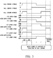
FIG. 3 is a schematic view showing an operation example of the brushless motor shown in FIG. 2.
FIG. 4 is a schematic view showing an operation example of the brushless motor shown in FIG. 2.
FIG. 5 is a flowchart showing an operation example of a control part shown in FIG. 2.
FIG. 6 is a flowchart showing an operation of a comparison example.
FIG. 7 is a waveform view showing an operation example of the brushless motor shown in FIG. 1.
FIG. 8 is a waveform view showing an operation of the comparison example.
DESCRIPTION OF THE EMBODIMENTS
Hereinafter, an embodiment of the present invention is described with reference to the drawings. FIG. 1 is a schematic view showing an entire configuration of a wiper apparatus 10 according to an embodiment of the present invention. The wiper apparatus 10 shown in FIG. 1 has a wiper arm 3 a on a driver seat side and a wiper arm 3 b on a passenger seat side that are provided swingably on a vehicle body. A wiper blade 4 a on a driver seat side is attached to the wiper arm 3 a on the driver seat side. A wiper blade 4 b on a passenger seat side is attached to the wiper arm 3 b on the passenger seat side. The wiper blade 4 a is in contact with a windshield 300 in a state of being pressed to the windshield 300 by a spring member (not shown) or the like that is provided inside the wiper arm 3 a. The wiper blade 4 b is in contact with the windshield 300 in a state of being pressed to the windshield 300 by a spring member (not shown) or the like that is provided inside the wiper arm 3 b. Two wiper shafts (a wiper shaft 9 a and a wiper shaft 9 b) are provided on the vehicle body. A base end part of the wiper arm 3 a is attached to the wiper shaft 9 a. A base end part of the wiper arm 3 b is attached to the wiper shaft 9 b.
Two motor apparatuses (a motor apparatus 100 a and a motor apparatus 100 b) are provided on the wiper apparatus 10. The motor apparatus 100 a allows the wiper arm 3 a to perform a swing movement. The motor apparatus 100 b allows the wiper arm 3 b to perform a swing movement. By the wiper apparatus 10 performing normal and reverse rotation controls of the two motor apparatuses 100 a, 100 b while synchronizing the two motor apparatuses 100 a, 100 b with each other, the wiper blade 4 a performs a swing movement in a wiped range 5 a indicated by a chain line, and the wiper blade 4 b performs a swing movement in a wiped range 5 b indicated by a chain line. The motor apparatus 100 a is constituted of a brushless motor (hereinafter, the brushless motor may be simply referred to as a motor) 1 a and a speed reduction mechanism 2 a. The motor apparatus 100 b is constituted of a brushless motor 1 b and a speed reduction mechanism 2 b. The brushless motor 1 a is connected via an in-vehicle LAN (Local Area Network) 400 to an ECU 200 which is a controller on a vehicle side. Switch information such as ON/OFF, Lo, Hi, and INT (intermittent operation) of a wiper switch, engine start information, vehicle speed information, and the like are input via the in-vehicle LAN 400 from the ECU 200 to the brushless motor 1 a. The brushless motors 1 a, 1 b are connected together by a communication line 500. In the wiper apparatus 10 shown in FIG. 1, by transmitting and receiving predetermined information via the communication line 500, the brushless motor 1 a and the brushless motor 1 b cooperate and control operations of the wiper blades 4 a, 4 b. The contents and the like of programs of the brushless motor 1 a and the brushless motor 1 b are partially different from each other, but it is possible to allow the basic configurations of the brushless motor 1 a and the brushless motor 1 b to be identical.
Next, a configuration example of the brushless motor 1 a shown in FIG. 1 is described with reference to FIG. 2. The brushless motor 1 a includes an inverter 11, a control part 12, a rotor 13, a stator 14, and Hall sensors 15 u, 15 v, 15 w.
The stator 14 has a stator core (not shown) and wirings 14 u, 14 v, 14 w that are wound around a plurality of slots included in the stator core. The wirings 14 u, 14 v, 14 w are a three-phase wiring in a delta connection. The wire connection method is not limited to the delta connection and may be a star connection.
The rotor 13 has a permanent magnet and is rotated in a state of facing the stator 14. The rotor 13 may be arranged on the inner side of the stator 14 to form an inner rotor structure. The rotor 13 may be arranged on the outer side of the stator 14 to form an outer rotor structure. The structures of the rotor 13 and the stator 14 are not limited and can be, for example, a four-pole six-slot structure in which the number of poles of a permanent magnet consisting of a north pole and a south pole is four, and the number of slots of the stator 14 is six.
The Hall sensors (position detection part) 15 u, 15 v, 15 w detect a rotation position of the rotor 13 by using a Hall element and output a detected result. Each of the Hall sensors 15 u, 15 v, 15 w detects each of positions that are displaced by an electric angle of 120° from one another. The Hall sensors 15 u, 15 v, 15 w output, to the control part 12, for example, a digital signal obtained by converting an analog signal having an amplitude that is proportional to a generated magnetic field by using the Hall element into a high level (H level) signal or a low level (L level) signal by a comparator. In the present embodiment, the Hall sensor 15 u outputs a digital signal that corresponds to a U-phase, the Hall sensor 15 v outputs a digital signal that corresponds to a V-phase, and the Hall sensor 15 w outputs a digital signal that corresponds to a W-phase. The Hall sensors 15 u, 15 v, 15 w of the present embodiment are arranged relative to the rotor 13 such that an electric angle becomes an advanced angle of 30° when the output of the inverter 11 is changed immediately at each position where an output signal level of the Hall sensor 15 u, 15 v, 15 w is changed, that is, at each position where an edge is generated at the output signal.
The inverter 11 has a plurality of switching elements 11 u 1, 11 u 2, 11 v 1, 11 v 2, 11 w 1, 11 w 2. The inverter 11 turns on or turns off the plurality of switching elements 11 u 1, 11 u 2, 11 v 1, 11 v 2, 11 w 1, 11 w 2 with a predetermined combination by using an external electric source 600 as a DC electric source and thereby supplies an AC current to the wirings 14 u, 14 v, 14 w as the three-phase wiring. The external electric source 600 includes, for example, a battery, a capacitor, and the like that are mounted on a vehicle. In the example shown in FIG. 2, the six switching elements 11 u 1, 11 u 2, 11 v 1, 11 v 2, 11 w 1, 11 w 2 are constituted of an n-channel MOSFET (metal-oxide semiconductor field-effect transistor). Drains of the switching elements 11 u 1, 11 v 1, 11 w 1 are commonly connected to a positive pole of the external electric source 600. A source of the switching element 11 u 1 is connected to a connection terminal (referred to as a U-phase terminal) between the wiring 14 u and the wiring 14 w and a drain of the switching element 11 u 2. A source of the switching element 11 v 1 is connected to a connection terminal (referred to as a V-phase terminal) between the wiring 14 v and the wiring 14 u and a drain of the switching element 11 v 2. A source of the switching element 11 w 1 is connected to a connection terminal (referred to as a W-phase terminal) between the wiring 14 w and the wiring 14 v and a drain of the switching element 11 w 2. Sources of the switching elements 11 u 2, 11 v 2, 11 w 2 are commonly connected to a negative pole (for example, an earth terminal) of the external electric source 600. The turn-on or turn-off operation of the switching elements 11 u 1, 11 u 2, 11 vl, 11 v 2, 11 w 1, 11 w 2 is controlled by the control part 12.
The control part 12 includes, for example, a microcomputer including a CPU (central processing unit), a RAM (random-access memory), a ROM (read-only memory), and the like and peripheral circuitry of the microcomputer and controls the switching elements 11 u 1, 11 u 2, 11 v 1, 11 v 2, 11 w 1, 11 w 2. Further, the control part 12 transmits and receives predetermined information between the ECU 200 and the brushless motor lb. Further, the control part 12 switches a power distribution pattern that represents a change of a power distribution state of the wirings 14 u, 14 v, 14 w of each phase of the three-phase wiring in response to the rotation of the rotor 13 to a low-speed power distribution pattern in use for a low-speed power distribution control or a high-speed power distribution pattern in use for a high-speed power distribution control and controls an ON or OFF state of the plurality of switching elements 11 u 1, 11 u 2, 11 v 1, 11 v 2, 11 wl, 11 w 2. Further, when controlling the plurality of switching elements 11 u 1, 11 u 2, 11 v 1, 11 v 2, 11 w 1, 11 w 2 to be in the ON or OFF state, the control part 12 controls a duty ratio (also referred to as a Duty output value) of each constant cycle to be in a predetermined limit value (also referred to as a Duty Limit value) or less by using a PWM (pulse width modulation) such that the rotation speed (also referred to as a motor speed) of the rotor 13 becomes a predetermined target value. Here, the control in a predetermined limit value or less is a control for providing an upper limit for a value of a current that flows through the wirings 14 u, 14 v, 14 w, and the limit value is changed depending on the rotation speed of the rotor 13, a voltage value of the external electric source 600, an ambient temperature, and the like. By setting this limit value, the wiper apparatus 10 including the motor apparatus 100 a is protected. The duty ratio is a value obtained by dividing an ON time by a summation value of the ON time and an OFF time in one cycle of the PWM.
With reference to FIG. 3 and FIG. 4, an example of the low-speed power distribution pattern in use for the low-speed power distribution control and an example of the high-speed power distribution pattern in use for the high-speed power distribution control are described. FIG. 3 shows the low-speed power distribution pattern in use for the low-speed power distribution control. FIG. 4 shows the high-speed power distribution pattern in use for the high-speed power distribution control. FIG. 3 and FIG. 4 use the horizontal axis for an electric angle and show an output signal of the Hall sensor 15 u (Hall sensor U-phase), an output signal of the Hall sensor 15 v (Hall sensor V-phase), an output signal of the Hall sensor 15 w (Hall sensor W-phase), a power distribution state of the switching element 11 u 1 (motor output U-phase (FET upper stage)), a power distribution state of the switching element 11 u 2 (motor output U-phase (FET lower stage)), a power distribution state of the switching element 11 v 1 (motor output V-phase (FET upper stage)), a power distribution state of the switching element 11 v 2 (motor output V-phase (FET lower stage)), a power distribution state of the switching element 11 w 1 (motor output W-phase (FET upper stage)), and a power distribution state of the switching element 11 w 2 (motor output W-phase (FET lower stage)) in this order from the upside. The power distribution state may be any of “ON”, “OFF”, and a control state of the duty ratio by the PWM.
In the low-speed power distribution pattern in use for the low-speed power distribution control shown in FIG. 3, for example, in a zone at the left end having an electric angle of 60°, the output signal of the Hall sensor 15 u (Hall sensor U-phase) represents “H”, the output signal of the Hall sensor 15 v (Hall sensor V-phase) represents “L”, and the output signal of the Hall sensor 15 w (Hall sensor W-phase) represents “H”, and in this case, the switching element 11 v 2 (motor output V-phase (FET lower stage)) represents “ON”, the switching element 11 w 1 (motor output W-phase (FET upper stage)) represents “PWM control”, and the other switching elements represent “OFF”. Further, for example, in the next zone having an electric angle of 60°, the output signal of the Hall sensor 15 u (Hall sensor U-phase) represents “H”, the output signal of the Hall sensor 15 v (Hall sensor V-phase) represents “L”, and the output signal of the Hall sensor 15 w (Hall sensor W-phase) represents “L”, and in this case, the switching element 11 u 2 (motor output U-phase (FET lower stage)) represents “ON”, the switching element 11 w 1 (motor output W-phase (FET upper stage)) represents “PWM control”, and the other switching elements represent “OFF”. In this way, in the low-speed power distribution pattern in use for the low-speed power distribution control shown in FIG. 3, when any of the output signal of the Hall sensor 15 u (Hall sensor U-phase), the output signal of the Hall sensor 15 v (Hall sensor V-phase), and the output signal of the Hall sensor 15 w (Hall sensor W-phase) is changed, the power distribution state of each phase is immediately changed by the control part 12. In this case, at each time when an edge (a rising edge or a falling edge) is generated at any of the Hall sensors 15 u, 15 v, 15 w, the motor output (that is, the output from the inverter 11 to the wirings 14 u, 14 v, 14 w) is switched. In the low-speed power distribution pattern in use for the low-speed power distribution control shown in FIG. 3, the advanced angle is 30°, and the power distribution angle is 120°.
On the other hand, in the high-speed power distribution pattern in use for the high-speed power distribution control shown in FIG. 4, the motor output is not switched at each time when an edge is generated at any of the Hall sensors 15 u, 15 v, 15 w, and the control part 12 switches the motor output at a timing (time) depending on a correction angle, a command advanced angle, and a command power distribution angle of the Hall sensors 15 u, 15 v, 15 w and the current rotation speed of the rotor 13 from the edge. Here, it is possible to calculate the rotation speed of the rotor 13 from the cycle of the output change of the Hall sensors 15 u, 15 v, 15 w. The correction angle of the Hall sensors 15 u, 15 v, 15 w is learning information for correcting the individual difference and, for example, can be calculated by measuring the deviation of the output change of the three Hall sensors 15 u, 15 v, 15 w. In the high-speed power distribution pattern, for example, the command advanced angle can be 20°, and the command power distribution angle can be 130° or the like. When the advanced angle is 20°, the advanced angle is decreased compared to a case in which the advanced angle is 30°, and thereby, it is possible to increase the rotation speed. When the power distribution angle is 130°, the power distribution angle is increased compared to a case in which the power distribution angle is 120°, and thereby, it is possible to increase a drive torque. In the high-speed power distribution pattern, the control part 12 changes the power distribution state of each phase at a timing that is shifted by a predetermined period of time which is varied in response to the rotation speed of the rotor 13 from the timing when the output signal of the Hall sensor 15 u, 15 v, 15 w is changed. Further, the control part 12 can allow the power distribution angle in the high-speed power distribution pattern to be larger than the power distribution angle in the low-speed power distribution pattern.
Next, with reference to FIG. 5, a switching operation between the low-speed power distribution control and the high-speed power distribution control by the control part 12 is described. FIG. 5 is a flowchart showing an example of a power distribution control switching operation by the control part 12. The control part 12 repeatedly performs a process shown in FIG. 5, for example, at a constant cycle after the operation is started. The control part 12 constantly selects the low-speed power distribution control when the operation is started.
First, the control part 12 determines whether or not the Duty output value is equal to or more than the Duty Limit value (Step S11). As described above, the Duty output value is a command value of a duty ratio that is calculated on the basis of the target rotation speed and the latest motor speed (rotation speed of the rotor 13), and the Duty Limit value is a limit value that is provided for protecting the wiper apparatus 10 including the motor apparatus 100 a. When the Duty output value exceeds the Duty Limit value, the Duty output value is limited to the Duty Limit value. The Duty output value being large means that the deviation between an actual rotation speed and the target rotation speed is large. The Duty output value being continuously set to the Duty Limit value means a state in which a load torque is large. Accordingly, by the determination process of Step S11, the control part 12 determines whether or not the state is a state within a predetermined range in which the load torque of the rotor 13 is relatively low.
For example, it is possible to set the Duty Limit value as described below. That is, first, the control part 12 calculates the Duty Limit value used as a reference for reducing the current that flows through the wirings 14 u, 14 v, 14 w to be less than an allowable value on the basis of the supply voltage of the external electric source 600. Next, the control part 12 measures the ambient temperature such as a board temperature that constitutes the control part 12 and corrects the Duty Limit value used as the reference on the basis of the measurement result of the temperature. Next, the control part 12 further corrects the corrected Duty Limit value on the basis of a motor acceleration and determines a final Duty Limit value.
When the Duty output value is equal to or more than the Duty Limit value (in a case of “Yes” in Step S11), the control part 12 sets a high-speed power distribution control switching timer value to a predetermined value (Step S12). The high-speed power distribution control switching timer value is a count value used for measuring a duration time of a state in which the Duty output value is less than the Duty Limit value. When the Duty output value is less than the Duty Limit value, the value of the high-speed power distribution control switching timer value is decreased by 1 in the process of Step S14 described below, and thereby, it is possible to measure the duration time of the state in which the Duty output value is less than the Duty Limit value. A value that corresponds to a temporal margin for allowing the motor speed to be capable of being stably maintained independently of the amplitude of the load after the low-speed power distribution control is switched to the high-speed power distribution control is set to the predetermined value that is set to the high-speed power distribution control switching timer value. It is possible to determine this predetermined value, for example, by an experiment or a simulation. For example, when a round-trip cycle in a case where the wiper is operated at a high speed is about 1 second, the predetermined value is set to a value less than half of about 0.5 seconds which is a movement time of one side, and thereby, it is possible to satisfy both of the stabilization of the operation and a performance improvement effect by switching between two kinds of power distribution controls.
On the other hand, when the Duty output value is not equal to or more than the Duty Limit value (in a case of “No” in Step S11), the control part 12 determines whether or not the high-speed power distribution control switching timer value is equal to 0 (Step S13). When the high-speed power distribution control switching timer value is not equal to 0 (in a case of “Yes” in Step S13), the control part 12 decreases the high-speed power distribution control switching timer value by 1 (Step S14).
When the process of Step S12 is finished, when the process of Step S14 is finished, or when the high-speed power distribution control switching timer value is equal to 0 (in a case of “No” in Step S13), the control part 12 determines whether or not the high-speed power distribution control is in operation (Step S15). When the high-speed power distribution control is in operation (in a case of “Yes” in Step S15), the control part 12 determines whether or not the motor speed is less than a predetermined threshold value (Step S16). When the motor speed is less than the predetermined threshold value (in a case of “Yes” in Step S16), the control part 12 performs switching from the high-speed power distribution control to the low-speed power distribution control (Step S17). That is, the control part 12 switches the power distribution pattern to the low-speed power distribution pattern in use for the low-speed power distribution control described with reference to FIG. 3 in Step S17 and then finishes the process shown in FIG. 5. On the other hand, when the motor speed is not less than the predetermined threshold value (in a case of “No” in Step S16), the control part 12 finishes the process shown in FIG. 5 without performing switching from the high-speed power distribution control to the low-speed power distribution control.
On the other hand, when the high-speed power distribution control is not in operation (in a case of “No” in Step S15), the control part 12 determines whether or not the motor speed is more than the predetermined threshold value (or the predetermined threshold value or more) and the high-speed power distribution control switching timer value is equal to 0 (Step S18). When the motor speed is more than the predetermined threshold value, and the high-speed power distribution control switching timer value is equal to 0 (in a case of “Yes” in Step S18), the control part 12 performs switching from the low-speed power distribution control to the high-speed power distribution control (Step S19). That is, the control part 12 switches the power distribution pattern to the high-speed power distribution pattern in use for the high-speed power distribution control described with reference to FIG. 4 in Step S19 and then finishes the process shown in FIG. 5. On the other hand, when the motor speed is not more than the predetermined threshold value, or the high-speed power distribution control switching timer value is not equal to 0 (in a case of “No” in Step S18), the control part 12 finishes the process shown in FIG. 5 without performing switching from the low-speed power distribution control to the high-speed power distribution control.
In the operation example shown in FIG. 5, the control part 12 performs the switching process between the low-speed power distribution control and the high-speed power distribution control as described below. That is, when the high-speed power distribution control is in operation, and the motor speed is less than the predetermined threshold value, the control part 12 performs switching from the high-speed power distribution control to the low-speed power distribution control. On the other hand, when the low-speed power distribution control is in operation, the motor speed is more than the predetermined threshold value, and a state in which the Duty output value is smaller than the Duty Limit value is continued for a predetermined period of time, the control part 12 performs switching from the low-speed power distribution control to the high-speed power distribution control. In this case, the control part 12 switches the power distribution pattern to the low-speed power distribution pattern in a case where the rotation speed of the rotor 13 is less than the predetermined threshold value and switches the power distribution pattern to the high-speed power distribution pattern when a state in which the load of the rotor 13 is within a predetermined range is continued for a predetermined period of time in a case where the rotation speed of the rotor 13 is more than the threshold value (or equal to or more than the threshold value). According to this configuration, for example, when the load applied to the motor is large, and the motor speed is slow, the low-speed power distribution control can be continued without performing switching from the low-speed power distribution control to the high-speed power distribution control. Therefore, according to the brushless motors 1 a, 1 b of the present embodiment, it is possible to appropriately switch between the low-speed control and the high-speed control.
Next, with reference to FIG. 7, a verification result using an actual machine of the switching operation of the power distribution control described with reference to FIG. 5 is described. For comparison, an experimental result (FIG. 8) of a case (hereinafter, referred to as a comparison example) in which the switching process of the power distribution control is performed according to the flow shown in FIG. 6 is also described.
FIG. 6 is a flowchart showing an operation of the comparison example in which part of the operation shown in FIG. 5 is changed. In the comparison example, after the operation is started, similarly to the case of FIG. 5, the control part 12 repeatedly performs the process shown in FIG. 6 at a constant cycle. Also, in the comparison example, the control part 12 constantly selects the low-speed power distribution control when the operation is started.
In an operation example shown in FIG. 6, first, the control part 12 determines whether or not the high-speed power distribution control is in operation (Step S101). When the high-speed power distribution control is in operation (in a case of “Yes” in Step S101), the control part 12 determines whether or not the motor speed is less than a predetermined threshold value (Step S102). The threshold value used in this Step S102 and Step S104 are the same as the threshold value used in Step S16 and Step S18 of FIG. 5. When the motor speed is less than the predetermined threshold value (in a case of “Yes” in Step S102), the control part 12 performs switching to the low-speed power distribution control similarly to Step S17 of FIG. 5 (Step S103). On the other hand, when the high-speed power distribution control is not in operation (in a case of “No” in Step S101), the control part 12 determines whether or not the motor speed is more than a predetermined threshold value (Step S104). When the motor speed is more than the predetermined threshold value (in a case of “Yes” in Step S104), the control part 12 performs switching to the high-speed power distribution control similarly to Step S19 of HG. 5 (Step S105).
Next, with reference to FIG. 7 and FIG. 8, a verification result using an actual machine is described. At the time of the verification of FIG. 7 and FIG. 8, a constant high load is applied to the brushless motor 1 a. The load is not a high load by which it is impossible to start the motor. FIG. 7 shows a case of the present embodiment (a case of the flow shown in FIG. 5), and FIG. 8 shows a case of the comparison example (a case of the flow shown in FIG. 6). FIG. 7 and FIG. 8 are waveform views representing a time change of the following data value in the RAM included in the control part 12. FIG. 7 and FIG. 8 use the horizontal axis for a time axis, display a motor angle (the angle of the rotor 13), a target speed, and a motor speed at the upper part, and display a Duty output value and a Duty Limit value at the lower part.
As shown in FIG. 8, in the comparison example, a motor stop and restart are repeated in a region surrounded by a chain line. This is because the following operations are repeated. That is, (1) the motor speed is rapidly decreased due to the large load applied to the motor. (2) An angle at which the motor speed is desired to be switched and a timing when the motor output is actually switched are displaced from each other, the motor characteristic is degraded, and the motor speed is further slowed (because the motor output switching timing is calculated from the motor speed). (3) The high-speed power distribution control is switched to the low-speed power distribution control due to the motor speed decrease, and the motor output is performed according to the Hall edge basis. (4) By performing the motor output according to the Hall edge basis, the motor characteristic returns, and therefore, the motor starts. (5) When the motor starts, the motor speed is present, and the power distribution control is switched to the high-speed power distribution control again. By repeating the above (1) to (5) operations, a failure operation arises.
On the other hand, as shown in FIG. 7, in a case of the switching operation of the low-speed power distribution control and the high-speed power distribution control of the present embodiment, even in a state where the load applied to the motor is high, it is possible to allow the motor to be continuously operated.
As described above, according to the embodiment of the present invention, when the load applied to the motor is large and while the motor is operated at a low speed, the power distribution control is not switched to the high-speed power distribution control for a predetermined period of time, and thereby, it is possible to prevent an unstable operation in which the low-speed power distribution control and the high-speed power distribution control are repeated. Further, the determination whether the load applied to the motor is large is performed on the basis of whether or not the Duty output value is limited, that is, whether or not the Duty output value is equal to or more than the Duty Limit value, and therefore, it is possible to easily simplify the configuration required for determining whether the load is large.
The embodiment of the present invention is not limited to the embodiment described above. For example, the above embodiment is described using a configuration in which the rotor 13, the stator 14, the inverter 11, and the control part 12 are integrally formed; however, for example, a configuration may be used in which the control part 12 is separated from the other constituents. Alternatively, a configuration may be used in which the control part 12 and the inverter 11 may be separated from the other constituents. Further, the above embodiment is described using a configuration in which two motor apparatuses 100 a, 100 b are provided on the wiper apparatus 10; however, the embodiment is not limited to the configuration. For example, a configuration may be used in which a single motor apparatus allows the wiper arms 3 a, 3 b to perform a swing movement via a link mechanism. Further, in the above embodiment, the brushless motors 1 a, 1 b are constituent elements of the wiper apparatus 10; however, the application field is not limited to a wiper apparatus.
DESCRIPTION OF THE REFERENCE SYMBOLS
1 a, 1 b brushless motor
10 wiper apparatus
100 a, 100 b motor apparatus
11 inverter
11 u 1, 11 u 2, 11 v 1, 11 v 2, 11 w 1, 11 w 2 switching element
12 control part
13 rotor
14 stator
14 u, 14 v, 14 w wiring
15 u, 15 v, 15 w Hall sensor

Claims (3)

The invention claimed is:
1. A brushless motor, comprising:
a stator having a three-phase winding;
a rotor that has a permanent magnet and that is rotated in a state of facing the stator;
an inverter that has a plurality of switching elements and that supplies an AC current to the three-phase wiring by turning on or turning off the plurality of switching elements; and
a control part that controls an ON or OFF state of the plurality of switching elements by switching a power distribution pattern that represents a change of a power distribution state of each phase of the three-phase wiring in response to a rotation of the rotor to a low-speed power distribution pattern in use for a low-speed power distribution control or a high-speed power distribution pattern in use for a high-speed power distribution control,
wherein the control part switches the power distribution pattern to the low-speed power distribution pattern in a case where a rotation speed of the rotor is less than a predetermined threshold value, and the control part switches the power distribution pattern to the high-speed power distribution pattern when a state in which a load of the rotor is within a predetermined range is continued for a predetermined period of time in a case where the rotation speed of the rotor is equal to or more than the threshold value,
the control part controls a duty ratio to be equal to or less than a predetermined limit value by using a pulse width modulation such that a rotation speed of the rotor becomes a predetermined target value when controlling the plurality of switching elements to be in an ON or OFF state, and
the control part determines that a load of the rotor is in a state within the predetermined range when the duty ratio for allowing the rotation speed of the rotor to be the target value is less than the limit value.
2. The brushless motor according to claim 1, comprising
a position detection part that detects a rotation position of the rotor,
wherein the low-speed power distribution pattern changes the power distribution state of each phase immediately at a timing when an output signal of the position detection part is changed,
the high-speed power distribution pattern changes the power distribution state of each phase at a timing that is shifted by a predetermined period of time which is varied in response to the rotation speed from the timing when the output signal of the position detection part is changed, and
a power distribution angle in the high-speed power distribution pattern is larger than a power distribution angle in the low-speed power distribution pattern.
3. A control method, comprising:
using a brushless motor that comprises:
a stator having a three-phase winding;
a rotor that has a permanent magnet and that is rotated in a state of facing the stator;
an inverter that has a plurality of switching elements and that supplies an AC current to the three-phase wiring by turning on or turning off the plurality of switching elements; and
a control part that controls an ON or OFF state of the plurality of switching elements by switching a power distribution pattern that represents a change of a power distribution state of each phase of the three-phase wiring in response to a rotation of the rotor to a low-speed power distribution pattern in use for a low-speed power distribution control or a high-speed power distribution pattern in use for a high-speed power distribution control, the method comprising:
by way of the control part, switching the power distribution pattern to the low-speed power distribution pattern in a case where a rotation speed of the rotor is less than a predetermined threshold value; and switching the power distribution pattern to the high-speed power distribution pattern when a state in which a load of the rotor is within a predetermined range is continued for a predetermined period of time in a case where the rotation speed of the rotor is equal to or more than the threshold value,
the control part controls a duty ratio to be equal to or less than a predetermined limit value by using a pulse width modulation such that a rotation speed of the rotor becomes a predetermined target value when controlling the plurality of switching elements to be in an ON or OFF state, and
the control part determines that a load of the rotor is in a state within the predetermined range when the duty ratio for allowing the rotation speed of the rotor to be the target value is less than the limit value.
US16/328,333 2016-09-01 2017-08-28 Brushless motor and control method Active 2039-01-12 US11316450B2 (en)

Applications Claiming Priority (4)

Application Number Priority Date Filing Date Title
JP2016-170801 2016-09-01
JPJP2016-170801 2016-09-01
JP2016170801A JP6802674B2 (en) 2016-09-01 2016-09-01 Brushless motor and control method
PCT/JP2017/030751 WO2018043405A1 (en) 2016-09-01 2017-08-28 Brushless motor and control method

Publications (2)

Publication Number Publication Date
US20210281197A1 US20210281197A1 (en) 2021-09-09
US11316450B2 true US11316450B2 (en) 2022-04-26

Family

ID=61301329

Family Applications (1)

Application Number Title Priority Date Filing Date
US16/328,333 Active 2039-01-12 US11316450B2 (en) 2016-09-01 2017-08-28 Brushless motor and control method

Country Status (5)

Country Link
US (1) US11316450B2 (en)
EP (1) EP3509206B1 (en)
JP (1) JP6802674B2 (en)
CN (1) CN109379901B (en)
WO (1) WO2018043405A1 (en)

Families Citing this family (2)

* Cited by examiner, † Cited by third party
Publication number Priority date Publication date Assignee Title
JP2020010576A (en) * 2018-07-12 2020-01-16 株式会社ミツバ Motor controller and motor control method
JP2023062838A (en) * 2021-10-22 2023-05-09 株式会社ミツバ Motor device, wiper device, and motor control method

Citations (16)

* Cited by examiner, † Cited by third party
Publication number Priority date Publication date Assignee Title
JPS574046B2 (en) 1975-01-22 1982-01-23
EP0716499A1 (en) 1994-12-07 1996-06-12 General Motors Corporation Controller for a brushless DC Motor
US5752209A (en) * 1994-10-20 1998-05-12 Koyo Seiko Co., Ltd. Electric power steering apparatus
CN1211650A (en) 1997-08-29 1999-03-24 株式会社东芝 Washer
JP2001352780A (en) * 2000-06-08 2001-12-21 Sanyo Electric Co Ltd Driver for brushless motor
JP2002142496A (en) 2000-11-06 2002-05-17 Denso Corp Controller for synchronous motor
JP2002233183A (en) 2001-01-31 2002-08-16 Matsushita Electric Ind Co Ltd Driving apparatus and method for brushless motor
JP2003111469A (en) 2001-09-28 2003-04-11 Sharp Corp Control method and controller of motor
JP2009100526A (en) 2007-10-16 2009-05-07 Mitsuba Corp Motor control device
US20100176757A1 (en) * 2009-01-09 2010-07-15 Toyota Jidosha Kabushiki Kaisha Controller for motor drive control system
CN102282755A (en) 2009-01-14 2011-12-14 松下电器产业株式会社 Motor driving device and electric equipment using same
CN102324882A (en) 2011-09-19 2012-01-18 河南工程学院 Wide range speed control system and current distribution method for hybrid excitation synchronous machine
JP2015168273A (en) 2014-03-04 2015-09-28 アスモ株式会社 wiper control device
US9219436B2 (en) * 2012-11-19 2015-12-22 Minebea Co., Ltd. Driving control device of motor
WO2016104328A1 (en) 2014-12-26 2016-06-30 東芝キヤリア株式会社 Motor drive device
CN106105012A (en) 2014-03-20 2016-11-09 日立汽车系统株式会社 The control device of brushless electric machine and control method

Patent Citations (16)

* Cited by examiner, † Cited by third party
Publication number Priority date Publication date Assignee Title
JPS574046B2 (en) 1975-01-22 1982-01-23
US5752209A (en) * 1994-10-20 1998-05-12 Koyo Seiko Co., Ltd. Electric power steering apparatus
EP0716499A1 (en) 1994-12-07 1996-06-12 General Motors Corporation Controller for a brushless DC Motor
CN1211650A (en) 1997-08-29 1999-03-24 株式会社东芝 Washer
JP2001352780A (en) * 2000-06-08 2001-12-21 Sanyo Electric Co Ltd Driver for brushless motor
JP2002142496A (en) 2000-11-06 2002-05-17 Denso Corp Controller for synchronous motor
JP2002233183A (en) 2001-01-31 2002-08-16 Matsushita Electric Ind Co Ltd Driving apparatus and method for brushless motor
JP2003111469A (en) 2001-09-28 2003-04-11 Sharp Corp Control method and controller of motor
JP2009100526A (en) 2007-10-16 2009-05-07 Mitsuba Corp Motor control device
US20100176757A1 (en) * 2009-01-09 2010-07-15 Toyota Jidosha Kabushiki Kaisha Controller for motor drive control system
CN102282755A (en) 2009-01-14 2011-12-14 松下电器产业株式会社 Motor driving device and electric equipment using same
CN102324882A (en) 2011-09-19 2012-01-18 河南工程学院 Wide range speed control system and current distribution method for hybrid excitation synchronous machine
US9219436B2 (en) * 2012-11-19 2015-12-22 Minebea Co., Ltd. Driving control device of motor
JP2015168273A (en) 2014-03-04 2015-09-28 アスモ株式会社 wiper control device
CN106105012A (en) 2014-03-20 2016-11-09 日立汽车系统株式会社 The control device of brushless electric machine and control method
WO2016104328A1 (en) 2014-12-26 2016-06-30 東芝キヤリア株式会社 Motor drive device

Non-Patent Citations (5)

* Cited by examiner, † Cited by third party
Title
Chinese Patent Office, Notice of Allowance issued in CN 201780035456.3 dated Jan. 25, 2022.
Chinese Patent Office, Office Action issued in CN 201780035456.3 dated Jul. 2, 2021.
European Patent Office, Search Report issued in EP 17846410.3 dated Mar. 4, 2020, 10 pages.
European Patent Office, Search Report issued in EP 17846410.3 dated Mar. 6, 2020, 10 pages.
PCT Office, International Search Report issued in PCT/JP2017/030751 dated Nov. 7, 2017, 4 pages.

Also Published As

Publication number Publication date
EP3509206B1 (en) 2022-02-09
CN109379901B (en) 2022-04-08
WO2018043405A1 (en) 2018-03-08
US20210281197A1 (en) 2021-09-09
CN109379901A (en) 2019-02-22
EP3509206A1 (en) 2019-07-10
JP6802674B2 (en) 2020-12-16
EP3509206A4 (en) 2020-04-08
JP2018038203A (en) 2018-03-08

Similar Documents

Publication Publication Date Title
US8040090B2 (en) Brushless motor controller and brushless motor
US10840842B2 (en) Motor driving device and method for measuring phase current in motor driving device
US8487564B2 (en) Brushless motor controller and method for controlling brushless motor
US20120306416A1 (en) Brushless motor drive device and drive method
US20090184678A1 (en) Permanent magnet ac motor systems and control algorithm restart methods
US8890451B2 (en) Sensorless control unit for brushless DC motor
US9130495B2 (en) Control system for brushless motor
US11316450B2 (en) Brushless motor and control method
US20130026960A1 (en) Brushless-motor drive apparatus
US8729840B2 (en) Sensorless control unit for brushless DC motor
US9000704B2 (en) Three-phase motor driving apparatus and three-phase motor driving method
JP2020048401A (en) Brushless motor, control method of the brushless motor, and control method of the wiper device
US10516362B2 (en) Motor driving device
JP2017169332A (en) Motor driving device
EP3624329B1 (en) Brushless motor, method for controlling the same and method for controlling wiper device
US10651777B2 (en) Drive apparatus and drive method for brushless motor
JP6938925B2 (en) Wiper device
US20230142956A1 (en) Motor controller, motor system and method for controlling motor
JP6239378B2 (en) WIPER DEVICE AND WIPER DEVICE CONTROL METHOD
US11014538B2 (en) Wiper device
US10864894B2 (en) Wiper device
JP4140454B2 (en) Electric power steering device
US20140222290A1 (en) Rotary electric machine control apparatus and electric power steering system using the same

Legal Events

Date Code Title Description
AS Assignment

Owner name: MITSUBA CORPORATION, JAPAN

Free format text: ASSIGNMENT OF ASSIGNORS INTEREST;ASSIGNOR:IKEDA, TAKESHI;REEL/FRAME:048438/0096

Effective date: 20190214

FEPP Fee payment procedure

Free format text: ENTITY STATUS SET TO UNDISCOUNTED (ORIGINAL EVENT CODE: BIG.); ENTITY STATUS OF PATENT OWNER: LARGE ENTITY

STPP Information on status: patent application and granting procedure in general

Free format text: NON FINAL ACTION MAILED

STPP Information on status: patent application and granting procedure in general

Free format text: RESPONSE TO NON-FINAL OFFICE ACTION ENTERED AND FORWARDED TO EXAMINER

STPP Information on status: patent application and granting procedure in general

Free format text: NOTICE OF ALLOWANCE MAILED -- APPLICATION RECEIVED IN OFFICE OF PUBLICATIONS

STPP Information on status: patent application and granting procedure in general

Free format text: PUBLICATIONS -- ISSUE FEE PAYMENT VERIFIED

STCF Information on status: patent grant

Free format text: PATENTED CASE