US11314314B2 - Head-mounted display apparatus and power saving control program for head-mounted display apparatus - Google Patents
Head-mounted display apparatus and power saving control program for head-mounted display apparatus Download PDFInfo
- Publication number
- US11314314B2 US11314314B2 US17/161,671 US202117161671A US11314314B2 US 11314314 B2 US11314314 B2 US 11314314B2 US 202117161671 A US202117161671 A US 202117161671A US 11314314 B2 US11314314 B2 US 11314314B2
- Authority
- US
- United States
- Prior art keywords
- state
- image
- head
- mounting state
- display apparatus
- Prior art date
- Legal status (The legal status is an assumption and is not a legal conclusion. Google has not performed a legal analysis and makes no representation as to the accuracy of the status listed.)
- Active, expires
Links
Images


Classifications
-
- G—PHYSICS
- G06—COMPUTING OR CALCULATING; COUNTING
- G06F—ELECTRIC DIGITAL DATA PROCESSING
- G06F3/00—Input arrangements for transferring data to be processed into a form capable of being handled by the computer; Output arrangements for transferring data from processing unit to output unit, e.g. interface arrangements
- G06F3/14—Digital output to display device ; Cooperation and interconnection of the display device with other functional units
- G06F3/147—Digital output to display device ; Cooperation and interconnection of the display device with other functional units using display panels
-
- G—PHYSICS
- G06—COMPUTING OR CALCULATING; COUNTING
- G06F—ELECTRIC DIGITAL DATA PROCESSING
- G06F1/00—Details not covered by groups G06F3/00 - G06F13/00 and G06F21/00
- G06F1/26—Power supply means, e.g. regulation thereof
- G06F1/32—Means for saving power
- G06F1/3203—Power management, i.e. event-based initiation of a power-saving mode
- G06F1/3234—Power saving characterised by the action undertaken
- G06F1/325—Power saving in peripheral device
- G06F1/3265—Power saving in display device
-
- A—HUMAN NECESSITIES
- A61—MEDICAL OR VETERINARY SCIENCE; HYGIENE
- A61B—DIAGNOSIS; SURGERY; IDENTIFICATION
- A61B5/00—Measuring for diagnostic purposes; Identification of persons
- A61B5/68—Arrangements of detecting, measuring or recording means, e.g. sensors, in relation to patient
- A61B5/6801—Arrangements of detecting, measuring or recording means, e.g. sensors, in relation to patient specially adapted to be attached to or worn on the body surface
- A61B5/6802—Sensor mounted on worn items
- A61B5/6803—Head-worn items, e.g. helmets, masks, headphones or goggles
-
- G—PHYSICS
- G01—MEASURING; TESTING
- G01C—MEASURING DISTANCES, LEVELS OR BEARINGS; SURVEYING; NAVIGATION; GYROSCOPIC INSTRUMENTS; PHOTOGRAMMETRY OR VIDEOGRAMMETRY
- G01C19/00—Gyroscopes; Turn-sensitive devices using vibrating masses; Turn-sensitive devices without moving masses; Measuring angular rate using gyroscopic effects
-
- G—PHYSICS
- G01—MEASURING; TESTING
- G01D—MEASURING NOT SPECIALLY ADAPTED FOR A SPECIFIC VARIABLE; ARRANGEMENTS FOR MEASURING TWO OR MORE VARIABLES NOT COVERED IN A SINGLE OTHER SUBCLASS; TARIFF METERING APPARATUS; MEASURING OR TESTING NOT OTHERWISE PROVIDED FOR
- G01D5/00—Mechanical means for transferring the output of a sensing member; Means for converting the output of a sensing member to another variable where the form or nature of the sensing member does not constrain the means for converting; Transducers not specially adapted for a specific variable
- G01D5/12—Mechanical means for transferring the output of a sensing member; Means for converting the output of a sensing member to another variable where the form or nature of the sensing member does not constrain the means for converting; Transducers not specially adapted for a specific variable using electric or magnetic means
- G01D5/14—Mechanical means for transferring the output of a sensing member; Means for converting the output of a sensing member to another variable where the form or nature of the sensing member does not constrain the means for converting; Transducers not specially adapted for a specific variable using electric or magnetic means influencing the magnitude of a current or voltage
- G01D5/24—Mechanical means for transferring the output of a sensing member; Means for converting the output of a sensing member to another variable where the form or nature of the sensing member does not constrain the means for converting; Transducers not specially adapted for a specific variable using electric or magnetic means influencing the magnitude of a current or voltage by varying capacitance
-
- G—PHYSICS
- G02—OPTICS
- G02B—OPTICAL ELEMENTS, SYSTEMS OR APPARATUS
- G02B27/00—Optical systems or apparatus not provided for by any of the groups G02B1/00 - G02B26/00, G02B30/00
- G02B27/01—Head-up displays
- G02B27/017—Head mounted
-
- G—PHYSICS
- G02—OPTICS
- G02B—OPTICAL ELEMENTS, SYSTEMS OR APPARATUS
- G02B27/00—Optical systems or apparatus not provided for by any of the groups G02B1/00 - G02B26/00, G02B30/00
- G02B27/01—Head-up displays
- G02B27/017—Head mounted
- G02B27/0172—Head mounted characterised by optical features
-
- G—PHYSICS
- G02—OPTICS
- G02B—OPTICAL ELEMENTS, SYSTEMS OR APPARATUS
- G02B27/00—Optical systems or apparatus not provided for by any of the groups G02B1/00 - G02B26/00, G02B30/00
- G02B27/01—Head-up displays
- G02B27/017—Head mounted
- G02B27/0176—Head mounted characterised by mechanical features
-
- G—PHYSICS
- G06—COMPUTING OR CALCULATING; COUNTING
- G06F—ELECTRIC DIGITAL DATA PROCESSING
- G06F1/00—Details not covered by groups G06F3/00 - G06F13/00 and G06F21/00
- G06F1/16—Constructional details or arrangements
- G06F1/1613—Constructional details or arrangements for portable computers
- G06F1/163—Wearable computers, e.g. on a belt
-
- G—PHYSICS
- G06—COMPUTING OR CALCULATING; COUNTING
- G06F—ELECTRIC DIGITAL DATA PROCESSING
- G06F1/00—Details not covered by groups G06F3/00 - G06F13/00 and G06F21/00
- G06F1/16—Constructional details or arrangements
- G06F1/1613—Constructional details or arrangements for portable computers
- G06F1/1633—Constructional details or arrangements of portable computers not specific to the type of enclosures covered by groups G06F1/1615 - G06F1/1626
- G06F1/1684—Constructional details or arrangements related to integrated I/O peripherals not covered by groups G06F1/1635 - G06F1/1675
- G06F1/1686—Constructional details or arrangements related to integrated I/O peripherals not covered by groups G06F1/1635 - G06F1/1675 the I/O peripheral being an integrated camera
-
- G—PHYSICS
- G06—COMPUTING OR CALCULATING; COUNTING
- G06F—ELECTRIC DIGITAL DATA PROCESSING
- G06F1/00—Details not covered by groups G06F3/00 - G06F13/00 and G06F21/00
- G06F1/16—Constructional details or arrangements
- G06F1/1613—Constructional details or arrangements for portable computers
- G06F1/1633—Constructional details or arrangements of portable computers not specific to the type of enclosures covered by groups G06F1/1615 - G06F1/1626
- G06F1/1684—Constructional details or arrangements related to integrated I/O peripherals not covered by groups G06F1/1635 - G06F1/1675
- G06F1/1688—Constructional details or arrangements related to integrated I/O peripherals not covered by groups G06F1/1635 - G06F1/1675 the I/O peripheral being integrated loudspeakers
-
- G—PHYSICS
- G06—COMPUTING OR CALCULATING; COUNTING
- G06F—ELECTRIC DIGITAL DATA PROCESSING
- G06F1/00—Details not covered by groups G06F3/00 - G06F13/00 and G06F21/00
- G06F1/16—Constructional details or arrangements
- G06F1/1613—Constructional details or arrangements for portable computers
- G06F1/1633—Constructional details or arrangements of portable computers not specific to the type of enclosures covered by groups G06F1/1615 - G06F1/1626
- G06F1/1684—Constructional details or arrangements related to integrated I/O peripherals not covered by groups G06F1/1635 - G06F1/1675
- G06F1/1694—Constructional details or arrangements related to integrated I/O peripherals not covered by groups G06F1/1635 - G06F1/1675 the I/O peripheral being a single or a set of motion sensors for pointer control or gesture input obtained by sensing movements of the portable computer
-
- G—PHYSICS
- G06—COMPUTING OR CALCULATING; COUNTING
- G06F—ELECTRIC DIGITAL DATA PROCESSING
- G06F1/00—Details not covered by groups G06F3/00 - G06F13/00 and G06F21/00
- G06F1/26—Power supply means, e.g. regulation thereof
- G06F1/32—Means for saving power
- G06F1/3203—Power management, i.e. event-based initiation of a power-saving mode
- G06F1/3206—Monitoring of events, devices or parameters that trigger a change in power modality
- G06F1/3215—Monitoring of peripheral devices
-
- G—PHYSICS
- G06—COMPUTING OR CALCULATING; COUNTING
- G06F—ELECTRIC DIGITAL DATA PROCESSING
- G06F1/00—Details not covered by groups G06F3/00 - G06F13/00 and G06F21/00
- G06F1/26—Power supply means, e.g. regulation thereof
- G06F1/32—Means for saving power
- G06F1/3203—Power management, i.e. event-based initiation of a power-saving mode
- G06F1/3206—Monitoring of events, devices or parameters that trigger a change in power modality
- G06F1/3231—Monitoring the presence, absence or movement of users
-
- G—PHYSICS
- G06—COMPUTING OR CALCULATING; COUNTING
- G06F—ELECTRIC DIGITAL DATA PROCESSING
- G06F1/00—Details not covered by groups G06F3/00 - G06F13/00 and G06F21/00
- G06F1/26—Power supply means, e.g. regulation thereof
- G06F1/32—Means for saving power
- G06F1/3203—Power management, i.e. event-based initiation of a power-saving mode
- G06F1/3234—Power saving characterised by the action undertaken
- G06F1/3287—Power saving characterised by the action undertaken by switching off individual functional units in the computer system
-
- G—PHYSICS
- G06—COMPUTING OR CALCULATING; COUNTING
- G06F—ELECTRIC DIGITAL DATA PROCESSING
- G06F3/00—Input arrangements for transferring data to be processed into a form capable of being handled by the computer; Output arrangements for transferring data from processing unit to output unit, e.g. interface arrangements
- G06F3/01—Input arrangements or combined input and output arrangements for interaction between user and computer
- G06F3/011—Arrangements for interaction with the human body, e.g. for user immersion in virtual reality
-
- G—PHYSICS
- G06—COMPUTING OR CALCULATING; COUNTING
- G06F—ELECTRIC DIGITAL DATA PROCESSING
- G06F3/00—Input arrangements for transferring data to be processed into a form capable of being handled by the computer; Output arrangements for transferring data from processing unit to output unit, e.g. interface arrangements
- G06F3/16—Sound input; Sound output
- G06F3/165—Management of the audio stream, e.g. setting of volume, audio stream path
-
- G—PHYSICS
- G06—COMPUTING OR CALCULATING; COUNTING
- G06T—IMAGE DATA PROCESSING OR GENERATION, IN GENERAL
- G06T7/00—Image analysis
- G06T7/97—Determining parameters from multiple pictures
-
- G—PHYSICS
- G09—EDUCATION; CRYPTOGRAPHY; DISPLAY; ADVERTISING; SEALS
- G09G—ARRANGEMENTS OR CIRCUITS FOR CONTROL OF INDICATING DEVICES USING STATIC MEANS TO PRESENT VARIABLE INFORMATION
- G09G3/00—Control arrangements or circuits, of interest only in connection with visual indicators other than cathode-ray tubes
- G09G3/20—Control arrangements or circuits, of interest only in connection with visual indicators other than cathode-ray tubes for presentation of an assembly of a number of characters, e.g. a page, by composing the assembly by combination of individual elements arranged in a matrix no fixed position being assigned to or needed to be assigned to the individual characters or partial characters
- G09G3/22—Control arrangements or circuits, of interest only in connection with visual indicators other than cathode-ray tubes for presentation of an assembly of a number of characters, e.g. a page, by composing the assembly by combination of individual elements arranged in a matrix no fixed position being assigned to or needed to be assigned to the individual characters or partial characters using controlled light sources
- G09G3/30—Control arrangements or circuits, of interest only in connection with visual indicators other than cathode-ray tubes for presentation of an assembly of a number of characters, e.g. a page, by composing the assembly by combination of individual elements arranged in a matrix no fixed position being assigned to or needed to be assigned to the individual characters or partial characters using controlled light sources using electroluminescent panels
- G09G3/32—Control arrangements or circuits, of interest only in connection with visual indicators other than cathode-ray tubes for presentation of an assembly of a number of characters, e.g. a page, by composing the assembly by combination of individual elements arranged in a matrix no fixed position being assigned to or needed to be assigned to the individual characters or partial characters using controlled light sources using electroluminescent panels semiconductive, e.g. using light-emitting diodes [LED]
- G09G3/3208—Control arrangements or circuits, of interest only in connection with visual indicators other than cathode-ray tubes for presentation of an assembly of a number of characters, e.g. a page, by composing the assembly by combination of individual elements arranged in a matrix no fixed position being assigned to or needed to be assigned to the individual characters or partial characters using controlled light sources using electroluminescent panels semiconductive, e.g. using light-emitting diodes [LED] organic, e.g. using organic light-emitting diodes [OLED]
-
- A—HUMAN NECESSITIES
- A61—MEDICAL OR VETERINARY SCIENCE; HYGIENE
- A61B—DIAGNOSIS; SURGERY; IDENTIFICATION
- A61B5/00—Measuring for diagnostic purposes; Identification of persons
- A61B5/02—Detecting, measuring or recording for evaluating the cardiovascular system, e.g. pulse, heart rate, blood pressure or blood flow
- A61B5/024—Measuring pulse rate or heart rate
- A61B5/02438—Measuring pulse rate or heart rate with portable devices, e.g. worn by the patient
-
- G—PHYSICS
- G01—MEASURING; TESTING
- G01P—MEASURING LINEAR OR ANGULAR SPEED, ACCELERATION, DECELERATION, OR SHOCK; INDICATING PRESENCE, ABSENCE, OR DIRECTION, OF MOVEMENT
- G01P15/00—Measuring acceleration; Measuring deceleration; Measuring shock, i.e. sudden change of acceleration
- G01P15/18—Measuring acceleration; Measuring deceleration; Measuring shock, i.e. sudden change of acceleration in two or more dimensions
-
- G—PHYSICS
- G02—OPTICS
- G02B—OPTICAL ELEMENTS, SYSTEMS OR APPARATUS
- G02B27/00—Optical systems or apparatus not provided for by any of the groups G02B1/00 - G02B26/00, G02B30/00
- G02B27/01—Head-up displays
- G02B27/0101—Head-up displays characterised by optical features
- G02B2027/0138—Head-up displays characterised by optical features comprising image capture systems, e.g. camera
-
- G—PHYSICS
- G02—OPTICS
- G02B—OPTICAL ELEMENTS, SYSTEMS OR APPARATUS
- G02B27/00—Optical systems or apparatus not provided for by any of the groups G02B1/00 - G02B26/00, G02B30/00
- G02B27/01—Head-up displays
- G02B27/017—Head mounted
- G02B2027/0178—Eyeglass type
-
- G—PHYSICS
- G09—EDUCATION; CRYPTOGRAPHY; DISPLAY; ADVERTISING; SEALS
- G09G—ARRANGEMENTS OR CIRCUITS FOR CONTROL OF INDICATING DEVICES USING STATIC MEANS TO PRESENT VARIABLE INFORMATION
- G09G2330/00—Aspects of power supply; Aspects of display protection and defect management
- G09G2330/02—Details of power systems and of start or stop of display operation
- G09G2330/021—Power management, e.g. power saving
- G09G2330/022—Power management, e.g. power saving in absence of operation, e.g. no data being entered during a predetermined time
-
- G—PHYSICS
- G09—EDUCATION; CRYPTOGRAPHY; DISPLAY; ADVERTISING; SEALS
- G09G—ARRANGEMENTS OR CIRCUITS FOR CONTROL OF INDICATING DEVICES USING STATIC MEANS TO PRESENT VARIABLE INFORMATION
- G09G2330/00—Aspects of power supply; Aspects of display protection and defect management
- G09G2330/02—Details of power systems and of start or stop of display operation
- G09G2330/021—Power management, e.g. power saving
- G09G2330/023—Power management, e.g. power saving using energy recovery or conservation
-
- G—PHYSICS
- G09—EDUCATION; CRYPTOGRAPHY; DISPLAY; ADVERTISING; SEALS
- G09G—ARRANGEMENTS OR CIRCUITS FOR CONTROL OF INDICATING DEVICES USING STATIC MEANS TO PRESENT VARIABLE INFORMATION
- G09G2330/00—Aspects of power supply; Aspects of display protection and defect management
- G09G2330/02—Details of power systems and of start or stop of display operation
- G09G2330/026—Arrangements or methods related to booting a display
-
- G—PHYSICS
- G09—EDUCATION; CRYPTOGRAPHY; DISPLAY; ADVERTISING; SEALS
- G09G—ARRANGEMENTS OR CIRCUITS FOR CONTROL OF INDICATING DEVICES USING STATIC MEANS TO PRESENT VARIABLE INFORMATION
- G09G2330/00—Aspects of power supply; Aspects of display protection and defect management
- G09G2330/02—Details of power systems and of start or stop of display operation
- G09G2330/027—Arrangements or methods related to powering off a display
-
- Y—GENERAL TAGGING OF NEW TECHNOLOGICAL DEVELOPMENTS; GENERAL TAGGING OF CROSS-SECTIONAL TECHNOLOGIES SPANNING OVER SEVERAL SECTIONS OF THE IPC; TECHNICAL SUBJECTS COVERED BY FORMER USPC CROSS-REFERENCE ART COLLECTIONS [XRACs] AND DIGESTS
- Y02—TECHNOLOGIES OR APPLICATIONS FOR MITIGATION OR ADAPTATION AGAINST CLIMATE CHANGE
- Y02D—CLIMATE CHANGE MITIGATION TECHNOLOGIES IN INFORMATION AND COMMUNICATION TECHNOLOGIES [ICT], I.E. INFORMATION AND COMMUNICATION TECHNOLOGIES AIMING AT THE REDUCTION OF THEIR OWN ENERGY USE
- Y02D10/00—Energy efficient computing, e.g. low power processors, power management or thermal management
Definitions
- the present disclosure relates to a head-mounted display apparatus and a power saving control program for a head-mounted display apparatus.
- JP-A-2015-156610 discloses an electronic apparatus that includes a wearable optical device.
- the electronic apparatus determines whether a state is at least any of a first state where the wearable optical device is mounted and usable and a second state where the wearable optical device is not used, controls a power supply state, based on the determination result, and achieves power saving.
- a state is determined as the second state when the wearable optical device is mounted or carried in an unusable state.
- a state where the wearable optical device is mounted on a head of a user and a state where the wearable optical device is removed from a body and is carried may be determined as the same state.
- a head-mounted display apparatus includes an image display unit configured to display an image, a sound output unit configured to output a sound, a mounting state determination unit configured to determine a mounting state of the head-mounted display apparatus, and an image sound output control unit configured to turn ON/OFF display of an image by the image display unit, and turn ON/OFF an output of a sound by the sound output unit, based on the mounting state, where the mounting state determination unit determines whether the mounting state is a first state where the head-mounted display apparatus is mounted in a position in which an image is visually recognizable, and determines whether the mounting state is a second state where the head-mounted display apparatus is mounted on a head, and the image sound output control unit is configured to turn ON display of an image and an output of a sound when the mounting state is the first state, turn OFF display of an image and turn ON an output of a sound when the mounting state is not the first state and is the second state, and turn OFF display of an image and an output
- FIG. 1 is an explanatory diagram illustrating a head-mounted display apparatus according to a first exemplary embodiment.
- FIG. 2 is a plan view illustrating a configuration of a main part of an optical system included in an image display unit.
- FIG. 3 is a diagram illustrating a configuration of a main part of the image display unit as viewed from a user.
- FIG. 4 is a block diagram illustrating a configuration of a control device.
- FIG. 5 is an output control flowchart for an image and a sound to an HMD performed by a CPU of the control device.
- FIG. 6 is an example of a first state determination flowchart performed by the CPU in step S 300 in FIG. 5 .
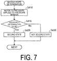
- FIG. 7 is an example of a second state determination flowchart performed by the CPU in step S 400 in FIG. 5 .
- FIG. 8 is an ON/OFF control flowchart of an image sound output performed by the CPU in step S 500 in FIG. 5 .
- FIG. 9 is an explanatory diagram illustrating a relationship between a mounting state of the HMD and ON/OFF of display of an image and a sound output of the HMD.
- FIG. 10 is an explanatory diagram illustrating a head-mounted display apparatus according to a second exemplary embodiment.
- FIG. 11 is an example of a first state determination flowchart performed by the CPU in step S 300 in FIG. 5 in the second exemplary embodiment.
- FIG. 12 is an explanatory diagram illustrating a head-mounted display apparatus according to a third exemplary embodiment.
- FIG. 13 is an example of a first state determination flowchart performed by the CPU in step S 300 in FIG. 5 in the third exemplary embodiment.
- FIG. 14 is an image sound output control flowchart illustrating step S 500 in FIG. 5 in a fourth exemplary embodiment.
- FIG. 15 is an explanatory diagram illustrating a head-mounted display apparatus according to a fifth exemplary embodiment.
- FIG. 16 is an explanatory diagram illustrating a relationship between a mounting state of an HMD in the fifth exemplary embodiment and ON/OFF of display of an image and a sound output of the HMD.
- FIG. 1 is an explanatory diagram of a head-mounted display apparatus 10 according to a first exemplary embodiment.
- the head-mounted display apparatus 10 is a display apparatus to be mounted on a head of the user and is also referred to as a head-mounted display (HMD).
- HMD head-mounted display
- the head-mounted display apparatus 10 is also referred to as an HMD 10 .
- the HMD 10 is a see-through (transmission-type) head-mounted display apparatus that provides an image appearing in an outside scenery visually recognized through glasses.
- the HMD 10 includes an image display unit 20 and a control device (controller) 100 configured to control the image display unit 20 .
- the image display unit 20 is a head-mounted body to be mounted on the head of the user and has an eyeglasses-like shape.
- the image display unit 20 includes a support body including a right holding portion 21 , a left holding portion 23 , and a front frame 27 and further includes, on the support body, a right display unit 22 , a left display unit 24 , a right light-guiding plate 26 , and a left light-guiding plate 28 .
- the right holding portion 21 and the left holding portion 23 are each coupled to the front frame 27 by hinges 37 and 38 such that the right holding portion 21 and the left holding portion 23 can be open and closed.
- the right holding portion 21 and the left holding portion 23 extend rearward from ends of the front frame 27 to hold the image display unit 20 on the head of the user in a manner similar to the temples of a pair of eyeglasses.
- one of both the ends of the front frame 27 located on the right side of the user in a mounting state of the image display unit 20 is referred to as an end ER, and the other end located on the left side of the user in the mounting state is referred to as an end EL.
- the right holding portion 21 is provided to extend from the end ER of the front frame 27 to a position corresponding to the right temple of the user in the mounting state of the image display unit 20 .
- the left holding portion 23 is provided to extend from the end EL of the front frame 27 to a position corresponding to the left temple of the user in the mounting state of the image display unit 20 .
- Pressure sensors 45 and 46 are each provided on the hinge portion between the right holding portion 21 and the left holding portion 23 , and the front frame 27 .
- a width of the front frame 27 is formed narrower than a width of the head, and thus, when the HMD 10 is mounted on a head of the user, the right holding portion 21 and the left holding portion 23 are widened and pressure applied to the pressure sensors 45 and 46 increases. Whether or not the HMD 10 is mounted on the head of the user can be determined by detecting the pressure.
- the right light-guiding plate 26 and the left light-guiding plate 28 are provided in the front frame 27 .
- the right light-guiding plate 26 is located in front of the right eye of the user in the mounting state of the image display unit 20 to allow the right eye to visually recognize an image.
- the left light-guiding plate 28 is located in front of the left eye of the user in the mounting state of the image display unit 20 to allow the left eye to visually recognize an image.
- the front frame 27 has a shape coupling an end of the right light-guiding plate 26 and an end of the left light-guiding plate 28 to each other. The coupling position corresponds to a position between eyebrows of the user in the mounting state of the image display unit 20 .
- the front frame 27 includes a nose pad 35 that is provided in the coupling position between the right light-guiding plate 26 and the left light-guiding plate 28 , and that is in contact with a nose of the user in the mounting state of the image display unit 20 .
- the nose pad 35 , the right holding portion 21 , and the left holding portion 23 allow the image display unit 20 to be held on the head of the user.
- the nose pad 35 is provided with nose pad sensors 39 and 40 configured to detect whether the HMD 10 is in contact with the nose of the user.
- the nose pad sensors 39 and 40 are a capacitance touch sensor, for example.
- a pulse wave sensor configured to detect a pulse wave of the nasal artery may be used.
- the right display unit 22 is configured to display an image on the right light-guiding plate 26 .
- the right display unit 22 is provided on the right holding portion 21 and located adjacent to the right temple of the user in the mounting state of the image display unit 20 .
- the left display unit 24 is configured to display an image on the left light-guiding plate 28 .
- the left display unit 24 is provided on the left holding portion 23 and located adjacent to the left temple of the user in the mounting state of the image display unit 20 .
- the right display unit 22 and the left display unit 24 are also collectively referred to as a “display driving unit”.
- the right light-guiding plate 26 and the left light-guiding plate 28 are optical parts (e.g., prisms) formed of a light transmission-type resin or the like, and are configured to guide imaging light output by the right display unit 22 and the left display unit 24 to the eyes of the user.
- optical parts e.g., prisms
- the control device 100 and the image display unit 20 are coupled to each other with a coupling cable 50 .
- the coupling cable 50 is detachably coupled to a conductive connector 125 provided in the control device 100 and is coupled from a tip AL of the left holding portion 23 to various circuits inside the image display unit 20 .
- the coupling cable 50 includes a metal cable or an optical fiber cable through which digital data is transmitted.
- the coupling cable 50 may further include a metal cable through which analog data is transmitted.
- a conductive connector 56 is provided in the middle of the coupling cable 50 .
- the conductive connector 56 is a jack to which a stereo mini-plug is coupled.
- the conductive connector 56 and the control device 100 are coupled to each other with, for example, a line through which an analog sound signal is transmitted.
- the conductive connector 56 is coupled to a headset 30 including a right earphone 32 and a left earphone 34 constituting a stereo headphone as a sound output unit configured to output a sound.
- the control device 100 is a device for controlling the HMD 10 (particularly, the image display unit 20 ).
- the control device 100 also functions as a supply device configured to supply an image and a sound.
- the HMD 10 receives a supply of an image and a sound from the control device 100 , displays the image on the image display unit 20 , and outputs the sound to the right earphone 32 and the left earphone 34 .
- the control device 100 includes the conductive connector 125 and a touch panel 180 .
- the touch panel 180 is configured to detect a touch operation from the user and output a signal corresponding to a detection content.
- the control device 100 controls the HMD 10 according to the signal. Any of various touch panels, such as an electrostatic-type touch panel, a pressure detection-type touch panel, and an optical touch panel, may be adopted as the touch panel 180 . An internal configuration of the control device 100 will be described later.
- FIG. 2 is a plan view illustrating a main part of a configuration of an optical system included in the image display unit 20 .
- FIG. 2 illustrates right eye RE and left eye LE of the user.
- the right display unit 22 and the left display unit 24 are arranged symmetrically on the right- and left-hand sides.
- the right display unit 22 includes an organic light emitting diode (OLED) unit 221 that is an organic EL and a right optical system 251 .
- the OLED unit 221 is configured to emit imaging light L.
- the right optical unit 251 includes a lens group and the like, and is configured to guide, to the right light-guiding plate 26 , the imaging light L emitted by the OLED unit 221 .
- the OLED unit 221 includes an OLED panel 223 and an OLED drive circuit 225 configured to drive the OLED panel 223 .
- the OLED panel 223 is a light emission type display panel including light-emitting elements configured to emit red (R) color light, green (G) color light, and blue (B) color light, respectively, by organic electro-luminescence.
- the OLED panel 223 includes a plurality of pixels arranged in a matrix, each of the plurality of pixels including one element of R, one element of G, and one element of B.
- the OLED drive circuit 225 is configured to select and power the light-emitting elements included in the OLED panel 223 to cause the light-emitting elements to emit light.
- the OLED drive circuit 225 is secured by bonding or the like onto a back surface of the OLED panel 223 , i.e., a back side of a light-emitting surface.
- the OLED drive circuit 225 may include, for example, a semiconductor device configured to drive the OLED panel 223 , and may be mounted onto a substrate secured to the back surface of the OLED panel 223 .
- the OLED panel 223 may be configured to include light-emitting elements, arranged in a matrix, that emit white color light, and color filters, disposed over the light-emitting elements, that correspond to the R color, the G color, and the B color, respectively.
- the OLED panel 223 may have a WRGB configuration including light-emitting elements configured to emit white (W) color light, in addition to light-emitting elements configured to emit R color light, G color light, and B color light, respectively.
- the right optical system 251 includes a collimate lens configured to collimate the imaging light L emitted from the OLED panel 223 .
- the imaging light L collimated by the collimate lens enters the right light-guiding plate 26 .
- a plurality of reflective surfaces configured to reflect the imaging light L are formed.
- the imaging light L is reflected multiple times inside the right light-guiding plate 26 and then, is guided to the right eye RE side.
- a half mirror 261 (reflective surface) located in front of the right eye RE is formed.
- the imaging light L reflected by the half mirror 261 is emitted from the right light-guiding plate 26 to the right eye RE.
- the imaging light L forms an image on the retina of the right eye RE to allow the user to visually recognize the image.
- the left display unit 24 includes an OLED unit 241 and a left optical system 252 .
- the OLED unit 241 is configured to emit the imaging light L.
- the left optical system 252 includes a lens group and the like, and is configured to guide, to the left light-guiding plate 28 , the imaging light L emitted by the OLED unit 241 .
- the OLED unit 241 includes an OLED panel 243 and an OLED drive circuit 245 configured to drive the OLED panel 243 .
- the OLED unit 241 , the OLED panel 243 , and the OLED drive circuit 245 are the same as the OLED unit 221 , the OLED panel 223 , and the OLED drive circuit 225 , respectively.
- the left optical system 252 is the same as the right optical system 251 .
- the imaging light L reflected by the half mirror 261 and outside light OL passing through the right light-guiding plate 26 enter the right eye RE of the user.
- the imaging light L reflected by a half mirror 281 and the outside light OL passing through the left light-guiding plate 28 enter the left eye LE of the user.
- the HMD 10 allows the imaging light L of the internally processed image and the outside light OL to enter the eyes of the user in an overlapped manner.
- the user views an outside scenery (real world) through the right light-guiding plate 26 and the left light-guiding plate 28 and also visually recognizes an image formed by the imaging light L overlapping the outside scenery.
- Each of the half mirror 261 and the half mirror 281 is configured to reflect the imaging light L output by each of the right display unit 22 and the left display unit 24 and extract an image.
- the right optical system 251 and the right light-guiding plate 26 are also collectively referred to as a “right light-guiding unit” and the left optical system 252 and the left light-guiding plate 28 are also collectively referred to as a “left light-guiding unit”.
- Configurations of the right light-guiding unit and the left light-guiding unit are not limited to the example described above, and can use any manner as long as the imaging light L forms an image in front of the eyes of the user.
- diffraction gratings or translucent reflective films may be used for the right light-guiding unit and the left light-guiding unit.
- FIG. 3 is a diagram illustrating a configuration of a main part of the image display unit 20 as viewed from the user.
- illustration of the coupling cable 50 , the right earphone 32 , the left earphone 34 , and the like is omitted.
- back sides of the right light-guiding plate 26 and the left light-guiding plate 28 can be visually recognized.
- the half mirror 261 configured to irradiate the imaging light L to the right eye RE, and the half mirror 281 configured to irradiate the imaging light L to the left eye LE can also be visually recognized as approximately square-shaped regions.
- the user visually recognizes an outside scenery through the entire areas of the right light-guiding plate 26 and the left light-guiding plate 28 including the half mirrors 261 and 281 , and also visually recognizes rectangular display images in the positions of the half mirrors 261 and 281 .
- the pressure sensors 45 and 46 are each provided on the hinge portion between the right holding portion 21 and the left holding portion 23 , and the front frame 27 .
- FIG. 4 is a block diagram illustrating a configuration of the control device 100 .
- the control device 100 includes a CPU 110 , an input/output interface 120 , an image sound data storage unit 130 , a memory 135 , an image output unit 140 , a sound output unit 150 , a mounting state determination unit 160 , an image sound output control unit 170 , a touch panel 180 , and a battery 190 .
- the input/output interface 120 includes the conductive connector 125 , and the coupling cable 50 ( FIG. 1 ) is inserted into the conductive connector 125 .
- the image sound data storage unit 130 stores data about an image and a sound to be output to the HMD 10 .
- the memory 135 stores a measurement value of various sensors of the HMD 10 .
- the image output unit 140 outputs an image stored in the image sound data storage unit 130 to the image display unit 20 of the HMD 10 .
- the sound output unit 150 outputs a sound stored in the image sound data storage unit 130 to the right earphone 32 and the left earphone 34 of the HMD 10 .
- the mounting state determination unit 160 determines a mounting state of the HMD 10 on the user by using various sensors provided in the HMD 10 and an image captured by a camera 36 .
- the image sound output control unit 170 turns ON/OFF an output of an image from the image output unit 140 to the image display unit 20 of the HMD 10 , and turns ON/OFF an output of a sound from the sound output unit 150 to the right earphone 32 and the left earphone 34 of the HMD 10 .
- the mounting state determination unit 160 and the image sound output control unit 170 are computer programs and are executed by the CPU 110 .
- the touch panel 180 is an input device to the control device 100 of the user, and is used to operate the HMD 10 by the user and select an image and a sound stored in the image sound data storage unit 130 . Further, the touch panel 180 displays an image.
- the battery 190 is a power supply configured to supply power to the control device 100 and the HMD 10 .
- FIG. 5 is an output control flowchart for an image and a sound to the HMD 10 performed by the CPU 110 of the control device 100 .
- step S 100 when the touch panel 180 of the control device 100 receives an instruction of a viewing start from the user, the CPU 110 causes the image output unit 140 and the sound output unit 150 to output an image and a sound to the HMD 10 , respectively.
- step S 200 the CPU 110 acquires information of the nose pad sensors 39 and 40 and the pressure sensors 45 and 46 , and stores the information in the memory 135 .
- step S 300 the CPU 110 uses the information of the nose pad sensors 39 and 40 , and determines whether a mounting state of the HMD 10 of the user is a first state.
- the first state refers to a state where the user wears the HMD 10 while the user can view an image.
- step S 400 the CPU 110 uses the information of the pressure sensors 45 and 46 , and determines whether the mounting state of the HMD 10 of the user is a second state.
- the second state refers to a state where the user wears the HMD 10 on the head of the user.
- step S 500 the CPU 110 controls ON/OFF of an output of an image and a sound depending on whether the mounting state of the HMD 10 of the user is the first state, the second state, or neither the first state nor the second state.
- step S 600 when the CPU 110 receives an instruction of discontinuance of viewing from the user, the CPU 110 terminates the processing, and, when the CPU 110 does not receive an instruction of discontinuance of viewing from the user, the CPU 110 returns the processing to step S 200 and repeats the processing described above.
- the user instructs discontinuance of viewing by, for example, making an input to the touch panel 180 .
- FIG. 6 is an example of a first state determination flowchart performed by the CPU 110 in step S 300 in FIG. 5 .
- the CPU 110 refers to, for determination, the output of the nose pad sensors 39 and 40 being acquired in step S 200 in FIG. 5 and stored in the memory 135 .
- the CPU 110 determines whether the nose of the user is in contact with the nose pad sensors 39 and 40 by using the output of the nose pad sensors 39 and 40 .
- the CPU 110 transitions the processing to step S 320 , and determines that the mounting state of the HMD 10 is the first state.
- the CPU 110 transitions the processing to step S 330 , and determines that the mounting state of the HMD 10 is not the first state.
- FIG. 7 is an example of a second state determination flowchart performed by the CPU 110 in step S 400 in FIG. 5 .
- the CPU 110 refers to, for determination, values of the pressure applied to the pressure sensors 45 and 46 being acquired in step S 200 in FIG. 5 and stored in the memory 135 .
- the CPU 110 determines whether both of the values of the pressure applied to the pressure sensors 45 and 46 are equal to or greater than a predetermined determination value. When both of the values of the pressure applied to the pressure sensors 45 and 46 are equal to or greater than the determination value, the CPU 110 transitions the processing to step S 420 , and determines that the mounting state of the HMD 10 is the second state where the HMD 10 is mounted on the head of the user.
- the CPU 110 transitions the processing to step S 430 in step S 310 , and determines that the mounting state of the HMD 10 is neither the first state nor the second state.
- FIG. 8 is an ON/OFF control flowchart of the image sound output performed by the CPU 110 in step S 500 in FIG. 5 .
- step S 510 when the CPU 110 determines that the mounting state of the HMD 10 is the first state, the CPU 110 transitions the processing to step S 530 , and, when the CPU 110 determines that the mounting state of the HMD 10 is not the first state, the CPU 110 transitions the processing to step S 520 .
- step S 520 when the CPU 110 determines that the mounting state of the HMD 10 is the second state, the CPU 110 transitions the processing to step S 540 , and, when the CPU 110 determines that the mounting state of the HMD 10 is not the second state, the CPU 110 transitions the processing to step S 550 .
- step S 530 the CPU 110 determines that the user wears the HMD 10 in front of the eyes, and transitions the processing to step S 535 .
- step S 535 the CPU 110 causes the image sound output control unit 170 to turn ON an output of an image from the image output unit 140 to the image display unit 20 of the HMD 10 , and causes the image sound output control unit 170 to turn ON an output of a sound from the sound output unit 150 to the HMD 10 .
- the HMD 10 maintains ON, and, when the output is OFF, the HMD 10 switches the output to ON.
- the output of the sound from the right earphone 32 and the left earphone 34 is ON, the HMD 10 maintains ON, and, when the output is OFF, the HMD 10 switches the output to ON.
- step S 540 the CPU 110 determines that the user wears the HMD 10 on the head, and transitions the processing to step S 545 .
- step S 545 the CPU 110 causes the image sound output control unit 170 to turn OFF an output of an image from the image output unit 140 to the image display unit 20 , and causes the image sound output control unit 170 to turn ON an output of a sound from the sound output unit 150 to the HMD 10 .
- the HMD 10 switches the output to OFF, and, when the output is OFF, the HMD 10 maintains OFF.
- the HMD 10 maintains ON, and, when the output is OFF, the HMD 10 switches the output to ON.
- step S 550 the CPU 110 determines non-mounting where the user does not wear the HMD 10 , and transitions the processing to step S 555 .
- step S 555 the CPU 110 causes the image sound output control unit 170 to turn OFF an output of an image from the image output unit 140 to the image display unit 20 , and causes the image sound output control unit 170 to turn OFF an output of a sound from the sound output unit 150 to the HMD 10 .
- the HMD 10 switches the output to OFF, and, when the output is OFF, the HMD 10 maintains OFF.
- the HMD 10 switches the output to OFF, and, when the output is OFF, the HMD 10 maintains OFF.
- FIG. 9 is an explanatory diagram illustrating a relationship between a mounting state of the HMD 10 and ON/OFF of display of an image and a sound output of the HMD 10 .
- the mounting state of the HMD 10 is the first state
- the image output is ON, but when the mounting state of the HMD 10 is not the first state, the image output is OFF.
- the mounting state of the HMD 10 is either the first state or the second state
- the sound output is ON, but when the mounting state of the HMD 10 is neither the first state nor the second state, the sound output is OFF.
- the CPU 110 determines whether the mounting state is the first state where the HMD 10 is mounted in a first position in which an image is visually recognizable, and determines whether the mounting state is the second state where the HMD 10 is mounted in a second position in which an image is not visually recognizable.
- the CPU 110 is configured to turn ON display of an image and an output of a sound when the mounting state is the first state, turn OFF display of an image and turn ON an output of a sound when the mounting state is not the first state and is the second state, and turn OFF display of an image and an output of a sound when the mounting state is neither the first state nor the second state. In this way, although the user wears the HMD 10 , when the user is not viewing an image, the CPU 110 turns OFF display of the image, and can thus reduce unnecessary power consumption of the battery 190 .
- the CPU 110 determines whether the mounting state is the first state or is not the first state depending on whether the nose of the user is in contact with the nose pad sensors 39 and 40 .
- the right light-guiding plate 26 is located in front of the right eye of the user and the left light-guiding plate 28 is located in front of the right eye of the user, and thus it can be determined that the user wears the HMD 10 in the first position in which an image is visually recognizable.
- the HMD 10 includes the front frame 27 configured to support the image display unit 20 , the temples 21 and 23 provided so as to sandwich the front frame 27 , the hinges 37 and 38 configured to couple the front frame 27 and the temples 21 and 23 in an openable and closable manner, and the pressure sensors 45 and 46 configured to detect pressure when the hinges 37 and 38 are open.
- the CPU 110 determines whether the mounting state of the HMD 10 is the second state or is not the second state by using a change in the pressure detected by the pressure sensors 45 and 46 .
- a spacing between the temples 21 and 23 is narrower than a width of the head.
- the CPU 110 can easily determine whether the mounting state of the HMD 10 is the second state or is not the second state by using the pressure applied to the pressure sensors 45 and 46 .
- FIG. 10 is an explanatory diagram illustrating a head-mounted display apparatus 11 (hereinafter referred to as an “HMD 11 ”) according to a second exemplary embodiment.
- the HMD 10 in the first exemplary embodiment and the HMD 11 in the second exemplary embodiment are different in a sensor for detecting a mounting state of the HMD 11 being provided in an image display unit 20 A, but other configurations are the same.
- the HMD 11 does not include the nose pad sensors 39 and 40 and instead includes an acceleration sensor 41 and a gyro sensor 42 .
- the acceleration sensor 41 and the gyro sensor 42 for detecting a mounting state, and a control flow using these sensors will be described.
- the image display unit 20 A of the HMD 11 includes the acceleration sensor 41 and the gyro sensor 42 in a coupling portion of the right light-guiding plate 26 and the left light-guiding plate 28 of the front frame 27 .
- the acceleration sensor 41 acquires acceleration in three directions with respect to the HMD 11 .
- the gyro sensor 42 acquires an angular speed about three axes of the HMD 11 . Note that, in the example in FIG. 10 , the acceleration sensor 41 and the gyro sensor 42 are provided in the coupling portion of the right light-guiding plate 26 and the left light-guiding plate 28 of the front frame 27 , but may be provided in another place of the HMD 11 .
- FIG. 11 is an example of a first state determination flowchart performed by the CPU 110 in step S 300 in FIG. 5 in the second exemplary embodiment.
- the CPU 110 sets a flag. Specifically, immediately after the power of the HMD 11 is turned ON, “Please press start button of touch panel 180 of control device 100 ” is displayed on the image display unit 20 of the HMD 11 or the touch panel 180 of the control device 100 when a viewing state is entered, and, when the start button is pressed, the CPU 110 determines that the state is the first state and sets a flag F 1 of the memory 135 to 1. Note that this step S 345 is performed only once immediately after the user turns on the power of the HMD 11 .
- step S 350 the CPU 110 acquires a mounting angle ⁇ A of the HMD 11 by using the gyro sensor 42 .
- step S 355 the CPU 110 acquires a value of the acceleration sensor 41 .
- step S 360 the CPU 110 determines whether the HMD 11 is grasped by the user.
- the CPU 110 determines that the HMD 11 is grasped by the user when the value of the acceleration sensor 41 is greater than a predetermined value.
- the CPU 110 transitions the processing to step S 365 .
- the CPU 110 transitions the processing to step S 385 .
- step S 365 the CPU 110 waits for the value of the acceleration sensor 41 to be stable.
- the value of the acceleration sensor 41 is stable, it can be determined that the HMD 11 is no longer grasped by the user.
- step S 370 the CPU 110 acquires a mounting angle ⁇ B of the HMD 11 by using the gyro sensor 42 .
- step S 375 the CPU 110 determines whether the mounting angle ⁇ of the HMD 11 changes to be equal to or greater than a threshold value. Specifically, the CPU 110 determines whether
- step S 380 the CPU 110 switches the flag F 1 to 0 when the flag F 1 is 1, and switches the flag F 1 to 1 when the flag F 1 is 0.
- step S 385 the CPU 110 determines whether the flag F 1 is 1. When the flag F 1 is 1, the CPU 110 transitions the processing to step S 390 , and determines that the mounting state of the HMD 11 is the first state. On the other hand, when the flag F 1 is 0, the CPU 110 transitions the processing to step S 395 , and determines that the mounting state of the HMD 11 is not the first state.
- the CPU 110 detects a vibration when the HMD 11 is picked up by using the acceleration sensor 41 , and measures the mounting angle ⁇ of the HMD 11 before and after the detection of the vibration by using the gyro sensor 42 .
- the mounting angle changes to be equal to or greater than a predetermined angle
- the CPU 110 can easily determine that a mounting state changes from a state that is the first state to a state that is not the first state or changes from a state that is not the first state to a state that is the first state.
- FIG. 12 is an explanatory diagram illustrating a head-mounted display apparatus 12 (hereinafter referred to as an “HMD 12 ”) according to a third exemplary embodiment.
- the HMD 10 in the first exemplary embodiment and the HMD 12 in the third exemplary embodiment are different in a sensor for detecting a mounting state, but other configurations are the same.
- a sensor for detecting a mounting state and a control flow using the sensor will be described.
- the HMD 12 includes contact sensors 43 and 44 in the front frame 27 , and a camera 36 is provided in a coupling portion of the right light-guiding plate 26 and the left light-guiding plate 28 of the front frame 27 .
- the camera 36 is a digital camera including an imaging element such as a charge-coupled device (CCD) and a complementary metal oxide semiconductor (CMOS), an imaging lens, and the like.
- the camera 36 is a monocular camera, but a stereo camera may be adopted.
- the camera 36 is configured to capture an image of at least part of an outside scenery (real space) in a front direction of the HMD 12 , i.e., in a direction of the field of view in a mounting state of the image display unit 20 .
- an outside scenery real space
- the contact sensors 43 and 44 are provided in the front frame 27 , but may be provided in the temples 21 and 23 . Further, when the camera 36 can also capture the front direction of the HMD 12 , the camera 36 may be provided in a place other than the coupling portion of the right light-guiding plate 26 and the left light-guiding plate 28 of the front frame 27 .
- FIG. 13 is an example of a first state determination flowchart performed by the CPU 110 in step S 300 in FIG. 5 in the third exemplary embodiment.
- the CPU 110 detects a contact of the user with the contact sensors 43 and 44 in step S 352 , the CPU 110 transitions the processing to step S 357 and captures a first image by using the camera 36 .
- the CPU 110 detects no contact of the user with the contact sensors 43 and 44 in step S 362
- the CPU 110 transitions the processing to step S 367 and captures a second image by using the camera 36 .
- step S 372 the CPU 110 compares the first image with the second image, and determines whether the image has changed significantly. For example, when a shape that is present in the first image is not present in the second image, when a shape that is not present in the first image is present in the second image, or when the first image and the second image have different hues, the CPU 110 determines that the image has changed significantly. In step S 372 , when the CPU 110 determines that the image has changed significantly, the CPU 110 transitions the processing to step S 377 , and, when the CPU 110 determines that it cannot be said that the image has changed significantly, the CPU 110 terminates the processing.
- step S 377 similarly to step S 380 in FIG. 11 in the second exemplary embodiment, when the mounting state before the user contacts the contact sensors 43 and 44 is the first state, the CPU 110 changes the first state to a state that is not the first state, and, when the mounting state before the user contacts the contact sensors 43 and 44 is not the first state, the CPU 110 changes the state to a state that is the first state.
- the CPU 110 detects whether the HMD 12 is touched by the user by using the contact sensors 43 and 44 , and acquires an image of the HMD 12 before and after the contact by using the camera 36 .
- the CPU 110 can easily determine that a mounting state changes from a state that is the first state to a state that is not the first state or changes from a state that is not the first state to a state that is the first state.
- the acceleration sensor 41 and the gyro sensor 42 are used in the second exemplary embodiment described above, and the contact sensors 43 and 44 and the camera 36 are used in the third exemplary embodiment. However, the acceleration sensor 41 and the camera 36 may be combined to determine a change in a mounting state, and the contact sensors 43 and 44 and the gyro sensor 42 may be combined to determine a change in a mounting state.
- FIG. 14 is an image sound output control flowchart illustrating step S 500 in FIG. 5 in a fourth exemplary embodiment.
- the image sound output control flowchart illustrated in FIG. 14 is different from the image sound output control flowchart illustrated in FIG. 8 in that the image sound output control flowchart illustrated in FIG. 14 includes steps S 545 and S 555 instead of steps S 540 and S 550 .
- the CPU 110 causes the image sound output control unit 170 to turn OFF an output of an image from the image output unit 140 to the image display unit 20 of the HMD 10 .
- the CPU 110 outputs a black image from the image output unit 140 to the HMD 10 .
- an output of an image from the image output unit 140 to the image display unit 20 of the HMD 10 is turned OFF, there is a possibility that the CPU 110 cannot recognize the HMD 10 as an external display, but when a black image is output, there can be a lower possibility that the CPU 110 cannot recognize the HMD 10 as an external display. Further, the power consumption of the organic EL can be suppressed.
- the CPU 110 first determines whether a state is the first state, and, when the state is not the first state, the CPU 110 determines whether the state is the second state. However, the CPU 110 may first determine whether a state is the second state, and, when the state is the second state, the CPU 110 may determine whether the state is the first state.
- FIG. 15 is an explanatory diagram illustrating a head-mounted display apparatus 13 (hereinafter also referred to as an “HMD 13 ”) according to a fifth exemplary embodiment.
- HMD 13 head-mounted display apparatus 13
- FIG. 15 illustration of the earphones 32 and 33 , the headset 30 , the coupling cable 50 , and the control device 100 is omitted.
- the HMD 12 is mounted on the head of the user by using a mounting band 90 .
- the mounting band 90 includes a mounting base portion 91 and a belt 92 coupled to the mounting base portion 91 .
- the mounting base portion 91 has a curved shape that matches a shape of a front head of a person.
- the belt 92 is mounted around the head of the user.
- the ends of the right holding portion 21 and the left holding portion 23 are coupled to a hinge portion 93 that couples the mounting base portion 91 and the belt 92 .
- the HMD 12 can flip up the image display unit 20 about the hinge portion 93 , as indicated by a broken line in FIG. 15 .
- a state where the image display unit 20 is not flipped up is a first state.
- Whether or not the image display unit 20 is flipped up can be determined by, for example, providing, in the hinge portion 93 , a sensor capable of detecting an angle formed by the mounting base portion 91 and the right holding portion 21 or the left holding portion 23 , and using the angle detected by a sensor 94 . Mounting of the image display unit 20 of the HMD 12 in a vertical direction of the head can be detected.
- the hinge portion 93 and the sensor 94 are provided in the ends of the right holding portion 21 and the left holding portion 23 .
- a hinge portion may be provided around above the eyes of the user to achieve flip-up of the image display unit 20 .
- a magnetic sensor for example, may be used as the sensor. When a magnetic sensor is provided in two places with a flip-up angle of 30° and 90°, a position of the image display unit 20 can be detected in two stages.
- FIG. 16 is an explanatory diagram illustrating a relationship between a mounting state of the HMD in the fifth exemplary embodiment and ON/OFF of display of an image and a sound output of the HMD.
- the CPU 110 turns ON display of an image in the image display unit 20 .
- the user can view the front without passing through the image display unit 20 by making the line of sight to the front, and the user can also glance at the image of the image display unit 20 by making the line of sight upward.
- the CPU 110 may display an image only in a lower portion of the image display unit 20 when a flip-up angle of the image display unit 20 is from 15° to 45°.
- An image may be displayed only in a region from the lower portion of the image display unit 20 according to a flip-up angle of the image display unit 20 . Further, when a flip-up angle of the image display unit 20 exceeds 45°, the CPU 110 turns OFF display of an image in the image display unit 20 .
- an optical sensor, a proximity sensor, and a potentiometer can be used as the sensor in addition to the magnetic sensor.
- FIG. 15 an example in which the right holding portion 21 , the left holding portion 23 , and the front frame 27 are flipped up is indicated, but a configuration in which the front frame 27 is flipped up without flipping up the right holding portion 21 and the left holding portion 23 may be adopted.
- the right display unit 22 and the left display unit 24 may be provided in the front frame 27 instead of the right holding portion 21 and the left holding portion 23 .
- a head-mounted display apparatus includes an image display unit configured to display an image, a sound output unit configured to output a sound, a mounting state determination unit configured to determine a mounting state of the head-mounted display apparatus, and an image sound output control unit configured to turn ON/OFF display of an image by the image display unit, and turn ON/OFF an output of a sound by the sound output unit, based on the mounting state, where the mounting state determination unit determines whether the mounting state is a first state where the head-mounted display apparatus is mounted in a position in which an image is visually recognizable, and determines whether the mounting state is a second state where the head-mounted display apparatus is mounted on a head, and the image sound output control unit is configured to turn ON display of an image and an output of a sound when the mounting state is the first state, turn OFF display of an image and turn ON an output of a sound when the mounting state is not the first state and is the second state, and turn OFF display of an image and an
- the mounting state determination unit easily distinguishes between the first state where the head-mounted display apparatus is mounted in a first position in which an image is visually recognizable and the second state where the head-mounted display apparatus is mounted on a head. In the second state, the image display unit does not display an image, and thus power saving can be achieved.
- the mounting state determination unit may determine a mounting state of the head-mounted display apparatus in a vertical direction of a head. According to this aspect, it is possible to determine whether the head-mounted display apparatus is flipped up and mounted.
- the head-mounted display apparatus may further include a nose pad sensor configured to detect whether a nose is in contact with the head-mounted display apparatus, where the mounting state determination unit may determine that a state is the first state when the head-mounted display apparatus is in contact with a nose, and determine that a state is not the first state when the head-mounted display apparatus is not in contact with a nose. According to this aspect, it is possible to easily determine whether a state is the first state.
- the head-mounted display apparatus may further include a front frame configured to support the image display unit, temples provided so as to sandwich the frame, a hinge configured to couple the front frame and the temples in an openable and closable manner and a pressure sensor configured to detect pressure when the hinge is open, where the mounting state determination unit may determine whether the mounting state is the second state or is not the second state by using pressure detected by the pressure sensor. According to this aspect, it is possible to easily determine whether the mounting state is the second state or is not the second state by using a change in pressure detected by the pressure sensor.
- the head-mounted display apparatus may further include an acceleration sensor and a gyro sensor, where the mounting state determination unit may detect a vibration when the head-mounted display apparatus is picked up by using the acceleration sensor, measure a mounting angle of the head-mounted display apparatus before and after the detection of the vibration by using the gyro sensor, and determine whether the mounting state is the first state or is not the first state by using a change in the mounting angle. According to this aspect, it is possible to easily determine whether the mounting state is the first state or is not the first state by using the acceleration sensor and the gyro sensor.
- the head-mounted display apparatus may further include a camera, where the mounting state determination unit may detect a vibration when the head-mounted display apparatus is picked up by using the acceleration sensor, acquire an image of the camera before and after the head-mounted display apparatus is picked up, and determine whether the mounting state is the first state or is not the first state by using a change in the image of the camera. According to this aspect, it is possible to easily determine whether the mounting stat is the first state or is not the first state by using a change in an image of the camera before and after the head-mounted display apparatus is picked up.
- the head-mounted display apparatus may further include a supply device configured to supply an image and a sound to the head-mounted display apparatus separately from the head-mounted display apparatus, where the image display unit may include an organic EL, and the supply device may supply a black image to the head-mounted display apparatus when a state is not the first state.
- the supply device supplies a black image to the head-mounted display apparatus when a state is not the first state, and thus the head-mounted display apparatus can be recognized as an external display.
- a power saving control program for a head-mounted display apparatus causing a control device of the head-mounted display apparatus to achieve a function of displaying an image on an image display unit, a function of outputting a sound to a sound output unit, a determination function of determining a mounting state of the head-mounted display apparatus, and an output control function of turning ON/OFF display of an image and turning ON/OFF an output of a sound, based on the mounting state, where the determination function includes a function of determining whether the mounting state is a first state where the head-mounted display apparatus is mounted in a position in which an image is visually recognizable, and determining whether the mounting state is a second state where the head-mounted display apparatus is mounted on a head, and the output control function includes a function of turning ON display of an image and an output of a sound when the mounting state is the first state, turning OFF display of an image and turning ON an output of a sound when
- the mounting state determination unit easily distinguishes between the first state where the head-mounted display apparatus is mounted in a first position in which an image is visually recognizable and the second state where the head-mounted display apparatus is mounted on a head, and does not output an image in the second state.
- power saving can be achieved.
- the present disclosure may be embodied in various forms other than the head-mounted display apparatus.
- the present disclosure can be achieved in exemplary embodiments such as a power saving control program for a head-mounted display apparatus and a non-temporary recording medium recording the power saving control program.
Landscapes
- Engineering & Computer Science (AREA)
- Physics & Mathematics (AREA)
- Theoretical Computer Science (AREA)
- General Physics & Mathematics (AREA)
- General Engineering & Computer Science (AREA)
- Computer Hardware Design (AREA)
- Health & Medical Sciences (AREA)
- Life Sciences & Earth Sciences (AREA)
- Human Computer Interaction (AREA)
- General Health & Medical Sciences (AREA)
- Optics & Photonics (AREA)
- Biomedical Technology (AREA)
- Pathology (AREA)
- Surgery (AREA)
- Public Health (AREA)
- Veterinary Medicine (AREA)
- Biophysics (AREA)
- Animal Behavior & Ethology (AREA)
- Molecular Biology (AREA)
- Medical Informatics (AREA)
- Heart & Thoracic Surgery (AREA)
- Computing Systems (AREA)
- Multimedia (AREA)
- Audiology, Speech & Language Pathology (AREA)
- Cardiology (AREA)
- Radar, Positioning & Navigation (AREA)
- Remote Sensing (AREA)
- Computer Vision & Pattern Recognition (AREA)
- Physiology (AREA)
- Controls And Circuits For Display Device (AREA)
- User Interface Of Digital Computer (AREA)
Abstract
Description
Claims (7)
Applications Claiming Priority (3)
| Application Number | Priority Date | Filing Date | Title |
|---|---|---|---|
| JPJP2020-013567 | 2020-01-30 | ||
| JP2020013567A JP2021121049A (en) | 2020-01-30 | 2020-01-30 | Power saving control program for head-mounted display devices and head-mounted display devices |
| JP2020-013567 | 2020-01-30 |
Publications (2)
| Publication Number | Publication Date |
|---|---|
| US20210240250A1 US20210240250A1 (en) | 2021-08-05 |
| US11314314B2 true US11314314B2 (en) | 2022-04-26 |
Family
ID=77270041
Family Applications (1)
| Application Number | Title | Priority Date | Filing Date |
|---|---|---|---|
| US17/161,671 Active 2041-01-29 US11314314B2 (en) | 2020-01-30 | 2021-01-29 | Head-mounted display apparatus and power saving control program for head-mounted display apparatus |
Country Status (2)
| Country | Link |
|---|---|
| US (1) | US11314314B2 (en) |
| JP (1) | JP2021121049A (en) |
Cited By (1)
| Publication number | Priority date | Publication date | Assignee | Title |
|---|---|---|---|---|
| US20240019704A1 (en) * | 2022-07-13 | 2024-01-18 | Google Llc | Multi-pivot hinge for head mounted wearable device |
Families Citing this family (7)
| Publication number | Priority date | Publication date | Assignee | Title |
|---|---|---|---|---|
| KR20220111575A (en) * | 2021-02-02 | 2022-08-09 | 삼성전자주식회사 | Electronic device and method for eye-tracking of user and providing augmented reality service thereof |
| US20240393872A1 (en) * | 2021-09-24 | 2024-11-28 | Apple Inc. | Avatar generation |
| CN114245259B (en) * | 2021-12-16 | 2026-02-03 | 歌尔科技有限公司 | Display system, head-mounted display device, and audio output device |
| US20230324984A1 (en) * | 2022-03-25 | 2023-10-12 | Meta Platforms Technologies, Llc | Adaptive sensors to assess user status for wearable devices |
| US20240036360A1 (en) * | 2022-07-26 | 2024-02-01 | Apple Inc. | Wear Detection |
| US12502091B2 (en) * | 2023-10-23 | 2025-12-23 | Pixart Imaging Inc. | Head-mounted apparatus and sensing method |
| KR102887993B1 (en) * | 2023-11-22 | 2025-11-24 | 서우석 | Dock device and remote control dock system including the same |
Citations (6)
| Publication number | Priority date | Publication date | Assignee | Title |
|---|---|---|---|---|
| US20090243970A1 (en) * | 2002-12-24 | 2009-10-01 | Nikon Corporation | Head mount display |
| US20150130711A1 (en) * | 2013-07-25 | 2015-05-14 | Lg Electronics Inc. | Head mounted display and method of controlling therefor |
| JP2015156610A (en) | 2014-02-21 | 2015-08-27 | ソニー株式会社 | Electronic apparatus and power supply control method |
| US20160062457A1 (en) * | 2014-09-01 | 2016-03-03 | Seiko Epson Corporation | Display device, method of controlling the same, and computer program |
| US20180176547A1 (en) * | 2016-12-19 | 2018-06-21 | Seiko Epson Corporation | Display apparatus and method for controlling display apparatus |
| US10055887B1 (en) * | 2015-02-19 | 2018-08-21 | Google Llc | Virtual/augmented reality transition system and method |
-
2020
- 2020-01-30 JP JP2020013567A patent/JP2021121049A/en active Pending
-
2021
- 2021-01-29 US US17/161,671 patent/US11314314B2/en active Active
Patent Citations (7)
| Publication number | Priority date | Publication date | Assignee | Title |
|---|---|---|---|---|
| US20090243970A1 (en) * | 2002-12-24 | 2009-10-01 | Nikon Corporation | Head mount display |
| US20150130711A1 (en) * | 2013-07-25 | 2015-05-14 | Lg Electronics Inc. | Head mounted display and method of controlling therefor |
| JP2015156610A (en) | 2014-02-21 | 2015-08-27 | ソニー株式会社 | Electronic apparatus and power supply control method |
| US20170045928A1 (en) | 2014-02-21 | 2017-02-16 | Sony Corporation | Electronic apparatus and method of controlling power supply |
| US20160062457A1 (en) * | 2014-09-01 | 2016-03-03 | Seiko Epson Corporation | Display device, method of controlling the same, and computer program |
| US10055887B1 (en) * | 2015-02-19 | 2018-08-21 | Google Llc | Virtual/augmented reality transition system and method |
| US20180176547A1 (en) * | 2016-12-19 | 2018-06-21 | Seiko Epson Corporation | Display apparatus and method for controlling display apparatus |
Cited By (2)
| Publication number | Priority date | Publication date | Assignee | Title |
|---|---|---|---|---|
| US20240019704A1 (en) * | 2022-07-13 | 2024-01-18 | Google Llc | Multi-pivot hinge for head mounted wearable device |
| US12158591B2 (en) * | 2022-07-13 | 2024-12-03 | Google Llc | Multi-pivot hinge for head mounted wearable device |
Also Published As
| Publication number | Publication date |
|---|---|
| JP2021121049A (en) | 2021-08-19 |
| US20210240250A1 (en) | 2021-08-05 |
Similar Documents
| Publication | Publication Date | Title |
|---|---|---|
| US11314314B2 (en) | Head-mounted display apparatus and power saving control program for head-mounted display apparatus | |
| US8866702B1 (en) | Use of optical display system as a visual indicator for a wearable computing device | |
| JP6160020B2 (en) | Transmission type display device, display method, and display program | |
| US9864198B2 (en) | Head-mounted display | |
| JP6089705B2 (en) | Display device and control method of display device | |
| CN108508603B (en) | Head-mounted display device, control method therefor, and recording medium | |
| US9348144B2 (en) | Display device and control method thereof | |
| US11393431B2 (en) | Display system, control program for information processor, and control method for information processor that are configured to adjust display of a first image on a first display unit based on the position of a second display unit | |
| US10121409B2 (en) | Display device, method of controlling display device, and program | |
| JP2020112982A (en) | Display system, display system control method, information processing device and information processing device control program | |
| US11322115B2 (en) | Display system, display control method, and program | |
| JP6464729B2 (en) | Display device and control method of display device | |
| US11269188B2 (en) | Display system, control program for information processing device, method for controlling information processing device, and display device | |
| US11353704B2 (en) | Head mounted device (HMD) coupled to smartphone executing personal authentication of a user | |
| JP6609920B2 (en) | Display device and control method of display device | |
| US11086441B2 (en) | Information processing apparatus, method for controlling information processing apparatus, and control program for information processing apparatus | |
| US11520414B2 (en) | Display system, control program for information processing device, and method for controlling information processing device | |
| JP2021047370A (en) | Display device, display device control method, display device control program, and display system |
Legal Events
| Date | Code | Title | Description |
|---|---|---|---|
| FEPP | Fee payment procedure |
Free format text: ENTITY STATUS SET TO UNDISCOUNTED (ORIGINAL EVENT CODE: BIG.); ENTITY STATUS OF PATENT OWNER: LARGE ENTITY |
|
| AS | Assignment |
Owner name: SEIKO EPSON CORPORATION, JAPAN Free format text: ASSIGNMENT OF ASSIGNORS INTEREST;ASSIGNORS:OKANO, KEIICHI;KOBAYASHI, SHINICHI;REEL/FRAME:055105/0916 Effective date: 20201201 |
|
| STPP | Information on status: patent application and granting procedure in general |
Free format text: DOCKETED NEW CASE - READY FOR EXAMINATION |
|
| STPP | Information on status: patent application and granting procedure in general |
Free format text: NON FINAL ACTION MAILED |
|
| STPP | Information on status: patent application and granting procedure in general |
Free format text: RESPONSE TO NON-FINAL OFFICE ACTION ENTERED AND FORWARDED TO EXAMINER |
|
| STPP | Information on status: patent application and granting procedure in general |
Free format text: NOTICE OF ALLOWANCE MAILED -- APPLICATION RECEIVED IN OFFICE OF PUBLICATIONS |
|
| STPP | Information on status: patent application and granting procedure in general |
Free format text: PUBLICATIONS -- ISSUE FEE PAYMENT VERIFIED |
|
| STCF | Information on status: patent grant |
Free format text: PATENTED CASE |
|
| MAFP | Maintenance fee payment |
Free format text: PAYMENT OF MAINTENANCE FEE, 4TH YEAR, LARGE ENTITY (ORIGINAL EVENT CODE: M1551); ENTITY STATUS OF PATENT OWNER: LARGE ENTITY Year of fee payment: 4 |