US11313112B2 - Drain adapter device - Google Patents
Drain adapter device Download PDFInfo
- Publication number
- US11313112B2 US11313112B2 US16/386,482 US201916386482A US11313112B2 US 11313112 B2 US11313112 B2 US 11313112B2 US 201916386482 A US201916386482 A US 201916386482A US 11313112 B2 US11313112 B2 US 11313112B2
- Authority
- US
- United States
- Prior art keywords
- drain
- low
- profile
- adapter
- insert
- Prior art date
- Legal status (The legal status is an assumption and is not a legal conclusion. Google has not performed a legal analysis and makes no representation as to the accuracy of the status listed.)
- Active
Links
Images


Classifications
-
- E—FIXED CONSTRUCTIONS
- E03—WATER SUPPLY; SEWERAGE
- E03C—DOMESTIC PLUMBING INSTALLATIONS FOR FRESH WATER OR WASTE WATER; SINKS
- E03C1/00—Domestic plumbing installations for fresh water or waste water; Sinks
- E03C1/12—Plumbing installations for waste water; Basins or fountains connected thereto; Sinks
- E03C1/20—Connecting baths or bidets to the wastepipe
-
- E—FIXED CONSTRUCTIONS
- E03—WATER SUPPLY; SEWERAGE
- E03F—SEWERS; CESSPOOLS
- E03F5/00—Sewerage structures
- E03F5/04—Gullies inlets, road sinks, floor drains with or without odour seals or sediment traps
- E03F5/0407—Floor drains for indoor use
- E03F5/0408—Floor drains for indoor use specially adapted for showers
-
- E—FIXED CONSTRUCTIONS
- E03—WATER SUPPLY; SEWERAGE
- E03F—SEWERS; CESSPOOLS
- E03F5/00—Sewerage structures
- E03F5/04—Gullies inlets, road sinks, floor drains with or without odour seals or sediment traps
- E03F2005/0412—Gullies inlets, road sinks, floor drains with or without odour seals or sediment traps with means for adjusting their position with respect to the surrounding surface
- E03F2005/0413—Gullies inlets, road sinks, floor drains with or without odour seals or sediment traps with means for adjusting their position with respect to the surrounding surface for height adjustment
-
- E—FIXED CONSTRUCTIONS
- E03—WATER SUPPLY; SEWERAGE
- E03F—SEWERS; CESSPOOLS
- E03F5/00—Sewerage structures
- E03F5/04—Gullies inlets, road sinks, floor drains with or without odour seals or sediment traps
- E03F2005/0412—Gullies inlets, road sinks, floor drains with or without odour seals or sediment traps with means for adjusting their position with respect to the surrounding surface
- E03F2005/0414—Gullies inlets, road sinks, floor drains with or without odour seals or sediment traps with means for adjusting their position with respect to the surrounding surface for inclination adjustment
-
- E—FIXED CONSTRUCTIONS
- E03—WATER SUPPLY; SEWERAGE
- E03F—SEWERS; CESSPOOLS
- E03F5/00—Sewerage structures
- E03F5/04—Gullies inlets, road sinks, floor drains with or without odour seals or sediment traps
- E03F5/0407—Floor drains for indoor use
- E03F5/0409—Devices for preventing seepage around the floor drain
Definitions
- the present disclosure is generally directed to drain adapters, in particular, toward floor and shower drain adapters.
- tiled drain systems especially tiled shower drain systems, include a drain base installed in a wooden subfloor of a shower.
- the drain base serves as an interconnection from the shower to a drainage system, waste line, and/or vent system of a building.
- the drain base includes a flange disposed around a periphery of the drain base that is configured to set a height of the drain base relative to the subfloor. In some cases, a surface of the flange may contact the subfloor seating the drain base to the subfloor.
- a clamping collar may be fastened to the drain base providing a threaded interface for a head adapter of the drain.
- the threaded interface may be a threaded hole disposed in a center of the clamping collar.
- a weep path may be provided in spaces between the clamping collar and the drain base, and/or the head adapter and the clamping collar, to allow water that collects underneath installed tile to move toward and through the drain to the drainage system of the building.
- the drain base, the clamping collar, and the head adapter may form what is known as the drain.
- a tiler Prior to finishing a tiled shower including this type of drain, a tiler is required to install a primary sloped mortar bed (sloping toward the drain), a waterproof pan liner on top of the primary sloped mortar bed, and a secondary sloped mortar bed disposed on top of the waterproof pan liner.
- the height of the head adapter relative to the subfloor may be adjusted to suit an overall height for the mortar and tile to be installed.
- tile can then be laid on top of the secondary mortar bed around the head adapter of the drain.
- the primary and/or secondary mortar also maintains the drain base, clamping collar, and even the head adapter in a fixed position relative to the subfloor.
- the installation provides a vapor path, for moisture to travel from an area between the floor tile and the waterproof pan liner to the walls of a building and/or other structural elements.
- the weep paths provide a flow path for waste water to flow through in the event of a drain clog and/or backup. In any event, the unwanted water may collect as described and cause mold problems, wet rot, and/or structural issues for a building.
- the drain with integrated bonding flange requires an adapter ring to be fastened to a pre-installed drain base using a gasket material and sealant. Once attached, the drain with integrated bonding flange may be interconnected to the adapter ring and mortared in place. For instance, the mortar may be disposed between the subfloor and the integrated flange maintaining the drain with integrated bonding flange in place. Further, the drain with integrated bonding flange requires a center drain gate support section to be bonded in place, as part of the drain, to set a final height of the drain relative to the subfloor.
- these types of drains require a center support section (e.g., a hollow pipe) which is adjusted to a desired tile height (e.g., cut to length), excluding the drain gate thickness, and then set in place with mortar.
- the installed drain gate extends above the center support section, and the integrated bonding flanges of the drain, providing a final height from the assembly from the subfloor.
- these types of drains (with integrated bonding flanges) provide a tall drain assembly (e.g., measured from the subfloor to the top of an installed drain gate that is coincident with the top of set tile) based on the number of required components and how each component interconnects with one another.
- these types of drains do not provide a completely sealed interface for a mortared shower that prevents the unwanted migration of vapor and/or water along a path through the mortar.
- these types of drains are configured to receive a specific type of drain gate and do not accommodate or receive threaded drain gates and/or strainer inserts.
- Embodiments described herein include a drain adapter device configured as a low-profile drain that, among other things, provides a dry seal between the drain base and installed floor drain components and can receive threaded drain gates and/or strainers.
- the drain adapter device can provide an installation height (e.g., measured from the subfloor to installed tile) that is less than 60% of the height of other drain systems.
- the drain adapter device may provide a low-profile drain system that includes universal receiving features configured to engage with strainers, drain gates, caps, etc.
- the universal receiving features may include standard threaded engagement features that threadedly-engage with mating features of a strainer, drain gate, cap, etc.
- FIG. 1A is a section view of a conventional drain system in a tiled environment
- FIG. 1B is a section view of a drain system in a tiled environment in accordance with embodiments of the present disclosure
- FIG. 2 is a section view of a low-profile drain system in a tiled environment in accordance with embodiments of the present disclosure
- FIG. 3A is an exploded perspective view of a low-profile drain system in accordance with embodiments of the present disclosure
- FIG. 3B is an elevation view of a low-profile drain system in accordance with embodiments of the present disclosure.
- FIG. 3C is an elevation section view taken through line A-A of FIG. 3B ;
- FIG. 4 shows multiple views of a low-profile drain adapter of low-profile drain system in accordance with embodiments of the present disclosure
- FIG. 5 shows multiple views of a threaded plate of a low-profile drain system in accordance with embodiments of the present disclosure
- FIG. 6 shows multiple views of a drain insert of a low-profile drain system in accordance with embodiments of the present disclosure
- FIG. 7 shows multiple views of an adjustable flange of a low-profile drain system in accordance with embodiments of the present disclosure
- FIG. 8A is an exploded perspective view of a low-profile drain system in accordance with embodiments of the present disclosure.
- FIG. 8B is an elevation view of a low-profile drain system in accordance with embodiments of the present disclosure.
- FIG. 8C is an elevation section view taken through line A-A of FIG. 8B ;
- FIG. 8D is a detail elevation section view of section 8 D of FIG. 8C ;
- FIG. 9 shows multiple views of a low-profile drain adapter of low-profile drain system in accordance with embodiments of the present disclosure.
- FIG. 10 is a section view of a low-profile drain system in a tiled environment in accordance with embodiments of the present disclosure
- FIG. 11A is an exploded perspective view of a low-profile drain system in accordance with embodiments of the present disclosure.
- FIG. 11B is a perspective view of the low-profile drain system of FIG. 11A ;
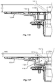
- FIG. 11C is an elevation view of a low-profile drain system in accordance with embodiments of the present disclosure.
- FIG. 11D is an elevation section view taken through line A-A of FIG. 11C ;
- FIG. 11E is a detail elevation section view of a first embodiment of a drain insert taken from section X of FIG. 11D ;
- FIG. 11F is a detail elevation section view of a second embodiment of a drain insert taken from section X of FIG. 11D ;
- FIG. 11G is a detail elevation section view of a third embodiment of a drain insert taken from section X of FIG. 11D ;
- FIG. 11H is a detail elevation section view of a fourth embodiment of a drain insert taken from section X of FIG. 11D ;
- FIG. 12 shows multiple views of a low-profile drain adapter of low-profile drain system in accordance with embodiments of the present disclosure
- FIG. 13 shows multiple views of a threaded plate of a low-profile drain system in accordance with embodiments of the present disclosure
- FIG. 14 shows multiple views of a drain insert of a low-profile drain system in accordance with embodiments of the present disclosure
- FIG. 15 shows multiple views of an adjustable flange of a low-profile drain system in accordance with embodiments of the present disclosure
- FIG. 16 shows multiple views of threaded plate gasket of a low-profile drain system in accordance with embodiments of the present disclosure
- FIG. 17A is an exploded perspective view of a low-profile drain system in accordance with embodiments of the present disclosure.
- FIG. 17B is a bottom perspective view of the low-profile drain system of FIG. 17A ;
- FIG. 17C is an elevation view of a low-profile drain system in accordance with embodiments of the present disclosure.
- FIG. 17D is an elevation section view taken through line A-A of FIG. 17C ;
- FIG. 17E is a detail elevation section view of circle B shown in FIG. 17D ;
- FIG. 18 shows multiple views of a low-profile drain adapter of the low-profile drain system shown in FIG. 17A ;
- FIG. 19 shows multiple views of a low-profile drain insert of the low-profile drain system shown in FIG. 17A ;
- FIG. 20 shows multiple views of a drain base interface gasket of the low-profile drain system shown in FIG. 17A ;
- FIG. 21 shows multiple views of a low-profile drain system at various stages of assembly in accordance with embodiments of the present disclosure.
- Embodiments of the present disclosure will be described in connection with low-profile drain systems and, in particular, shower drain systems.
- the devices and systems disclosed herein may interconnect with one or more existing, or pre-installed, plumbing components in a building or structure.
- the drain system 100 A may include a subfloor 102 including an aperture, or hole, with a drain base 104 disposed therein.
- the drain base 104 may include a flanged rim, or flange, that sits on the subfloor 102 , such that the subfloor 102 cannot pass therethrough.
- Attached to the drain base 104 is a clamping collar 108 .
- the clamping collar 108 may be fastened to the drain base 104 via one or more screws or bolts at a collar attachment interface 120 .
- the clamping collar 108 may include a set of internal threads configured to engage with mating threads of a head adapter 112 at a threaded interface 118 .
- the head adapter 112 may include a strainer, drain gate, and/or other drain filter feature.
- the distance from the subfloor 102 to the top of the head adapter 112 may define a drain height, H.
- the components may be substantially centerline symmetrical about drain center axis 114 .
- the drain system 100 A offers a number of features designed to seal a tiled environment relative to the drain base 104 .
- a primary sloped mortar bed 122 may be formed around a periphery of the drain base 104 including a gradual slope downward toward the drain center axis 114 of the drain base 104 . This slope allows water to gradually drain toward the drain base 104 and into a connected waste line.
- a waterproof membrane 106 e.g., waterproof liner, etc.
- the waterproof membrane 106 allows water that may collect under the tile 116 and in the mortar to move along a surface of the waterproof membrane 106 , through one or more weep paths of the drain base 104 and/or clamping collar 108 , into the drain (and connected line).
- the secondary sloped mortar bed 126 may be formed on the waterproof membrane 106 , the drain base 104 , and/or the clamping collar 108 , around a periphery of the head adapter 112 . Similar to the primary sloped mortar bed 122 , the secondary sloped mortar bed 126 includes a gradual slope downward toward the drain center axis 114 of the drain base 104 . This slope disposes the tile 116 at a sloped angle to the drain system 100 A, draining water toward the center of the drain base 104 and into a connected waste line.
- the drain system 100 A illustrated in FIG. 1A creates a vapor and/or fluid path 130 in the secondary sloped mortar bed 126 .
- water may collect in the secondary sloped mortar bed 126 , between the tile 116 and the waterproof membrane 106 , during routine use of the drain system 100 A (e.g., use of a shower, etc.).
- fluid may move from the drain base 104 and/or connected waste line, through the weep paths in the collar attachment interface 120 and/or drain base 104 into the secondary sloped mortar bed 126 .
- This backed-up material may then flow from the secondary sloped mortar bed 126 to one or more structural elements and/or unprotected areas in the structure/building along one or more vapor/fluid paths 130 .
- this drain system 100 A may not adequately seal the walls or environment around a drain from unwanted intrusion of moisture.
- FIG. 1B is a section view of a drain system 100 B in a tiled environment in accordance with embodiments of the present disclosure.
- the same subfloor 102 and drain base 104 are installed in a structure as described in conjunction with FIG. 1A .
- the integrated flange drain system 100 B may include an adapter ring 134 including a flexible seal area 136 configured to receive a pipe stem of a drain with integrated bonding flange 140 .
- the adapter ring 134 may elastically stretch around the stem providing the flexible seal area 136 around a complete periphery of the stem of the drain with integrated bonding flange 140 .
- the integrated flange drain system 100 B includes a primary sloped mortar bed 122 , a waterproof membrane 106 , and a secondary sloped mortar bed 126 .
- the secondary sloped mortar bed 126 shown in the integrated flange drain system 100 B of FIG. 1B supports a number of tiles 116 at a sloped, or angled, orientation relative to the drain base 104 and/or the drain center axis 114 .
- the drain with integrated bonding flange 140 includes a sloped bonding flange extending outwardly from the drain center axis 114 a distance to engage with the waterproof membrane 106 and/or the secondary sloped mortar bed 126 . This bonding flange provides a number of benefits, including an enhanced mortar bonding surface and a larger waterproof membrane 106 contact area.
- a center support ring 142 Disposed at the center of the drain with integrated bonding flange 140 , is a center support ring 142 (e.g., configured as a section of tubing) including an internal diameter configured to receive and engage with a drain gate 148 .
- the engagement may include a simple slip fit tube-in-tube engagement.
- the integrated flange drain system 100 B may include an adjustable flange 144 disposed around an outer diameter of the center support ring 142 configured to provide mortar setting surfaces for the integrated flange drain system 100 B.
- the adjustable flange 144 may be moved vertically, in either direction along the drain center axis 114 , to suit a desired height of the tile 116 relative to the subfloor 102 , e.g., height (H+Y).
- this height (H+Y) may be defined by the design of the integrated flange drain system 100 B.
- the height (H+Y) may be equal to the height, H, of the drain system 100 A shown in FIG. 1A and an additional amount, Y, representing a dimension of the number of components making up the integrated flange drain system 100 B above those shown in the drain system 100 A of FIG. 1A .
- FIGS. 2-9 describe various embodiments of a low-profile drain system 200 , 800 in accordance with embodiments of the present disclosure.
- the low-profile drain system 200 , 800 may include a dry-seal system comprising a threaded plate 212 and threaded plate gasket 208 attached to the drain base 104 . When attached, the dry-seal system prevents fluid, or vapor, from passing through the threaded plate gasket 208 and the threaded plate 212 at the sealed interface 220 .
- the low-profile drain adapter 204 , 804 may include a threaded stem section configured to engage with the threaded plate 212 at a threaded engagement 218 . As illustrated in the figures, this threaded engagement 218 allows the low-profile drain adapter 204 , 804 to be arranged closer to the drain base 104 , providing a lower-profile system 200 , 800 than the drain system 100 B illustrated in FIG. 1B . In some embodiments, the height, (H ⁇ N), of the low-profile drain system 200 , 800 may be less than the height, H, of the drain system 100 A illustrated in FIG. 1A .
- One or more of the components making up the low-profile drain system 200 , 800 may be made from plastic, polyvinyl chloride (PVC), polymer, steel, copper, iron, combinations thereof, and/or the like.
- PVC polyvinyl chloride
- the low-profile drain adapter 204 , 804 may include a drain insert 216 that nests at least partially inside a receiving area of the low-profile drain adapter 204 , 804 .
- the receiving area may orient the drain insert 216 in a position coaxial with the drain center axis 114 of the low-profile drain system 200 , 800 .
- the drain insert 216 may include insert engagement features 222 configured to receive a strainer, filter, drain gate, and/or other drain feature.
- the insert engagement features 222 may be configured as internal threads disposed in the drain insert 216 .
- the internal threads of the drain insert 216 may match the threads of the stem of the low-profile drain adapter 204 , 208 .
- the insert engagement features 222 may include a standard thread diameter and pitch that exactly, or substantially matches, a standard thread diameter and pitch of the threaded plate 212 and/or the stem of the low-profile drain adapter 204 , 804 .
- the low-profile drain system 200 , 800 may include an adjustable flange 224 that provides bonding surfaces for the secondary sloped mortar bed 126 .
- the adjustable flange 244 may be moved vertically, in either direction along the drain center axis 114 , to suit a desired height of the tile 116 relative to the subfloor 102 .
- the adjustable flange 224 may be moved to dispose the drain insert 216 a specific distance above the subfloor 102 .
- One or more surfaces of the adjustable flange 224 may engage with one or more surfaces of the low-profile drain adapter 204 .
- This engagement may set the height of the drain insert 216 disposed in a center aperture of the adjustable flange 224 .
- the adjustable flange 224 may engage with the drain insert 216 , in a tight tolerance fit such that the drain insert 216 and the adjustable flange 224 do not move relative one another absent an outside adjustment force (e.g., not gravity).
- FIG. 2 is a section view of a low-profile drain system 200 in a tiled environment in accordance with embodiments of the present disclosure.
- the low-profile drain system 200 shown in FIG. 2 is a schematic representation of the low-profile drain system 200 .
- FIG. 3A is an exploded perspective view of a low-profile drain system 200 in accordance with embodiments of the present disclosure.
- the low-profile drain system 200 in FIG. 3A shows the various components (e.g., the threaded plate gasket 208 , threaded plate 212 , low-profile drain adapter 204 , drain insert 216 , and the adjustable flange 224 ) exploded along the drain center axis 114 .
- the drain insert 216 includes a flange disposed about a periphery of the insert body. It should be appreciated that embodiments of the present disclosure may not require the flange as shown in FIG. 3A .
- the low-profile drain system 200 may include a threaded plate gasket 208 made of a compliant material, such as silicone, plastic, polymer, rubber, and/or combinations thereof. In any event, the threaded plate gasket 208 may include a first set of punched, or partially-punched, mount features 234 A.
- the first mount features 234 A may be one or more holes, or partially-punched, holes disposed around a center of the threaded plate gasket 208 in a first bolt circle diameter (“BCD”) having a first radius dimension measured from the center of the threaded plate gasket 208 .
- the threaded plate gasket 208 may include a second set of punched, or partially-punched, mount features 234 B.
- the second mount features 234 B may be one or more holes, or partially-punched, holes disposed around a center of the threaded plate gasket 208 in a second BCD having a second radius dimension measured from the center of the threaded plate gasket 208 that is different from the first radius dimension.
- the first and second mount features 234 A, 234 B may be offset from one another by an angle.
- the threaded plate 212 may include a flanged surface configured to engage with a surface of the threaded plate gasket 208 and seal the threaded plate gasket 208 to a drain base 104 .
- the threaded plate 212 may include drain engagement features 226 disposed on an internal diameter of the plate 212 .
- the drain engagement features 226 may correspond to internal threads configured to mate with the external threads 230 of the low-profile drain adapter 204 .
- the threaded plate 212 may include a number of drain base mounting features 232 sized to receive and contain fasteners in either the first BCD or the second BCD.
- the drain base mounting features 232 may be shaped as two-holes that overlap and are disposed side-by-side through the flange of the threaded plate 212 (e.g., forming a figure “8” aperture). Although not shaped as a straight slot, it should be appreciated that the drain base mounting features 232 could be a slot disposed through the flange of the drain insert 216 , without departing from the scope of the present disclosure.
- one or more components of the low-profile drain system 200 may include a number of mortar receiving features 238 .
- mortar may enter the mortar receiving features 238 and set therein fixing the low-profile drain system 200 relative to the subfloor 102 .
- the mortar receiving features 238 are shown disposed in the low-profile drain adapter 204 , the adjustable flange 224 , and the drain insert 216 , it should be appreciated that the low-profile drain system 200 may include more or fewer mortar receiving features 238 than shown in FIG. 3A .
- FIG. 3B is an elevation view of a low-profile drain system 200 , at least partially assembled, in accordance with embodiments of the present disclosure.
- FIG. 3C is an elevation section view taken through line A-A of FIG. 3B .
- FIG. 3C shows example dimensions of the low-profile drain system 200 , in the at least partially assembled state, in inches.
- the insert engagement features 222 of the drain insert 216 are disposed inside the low-profile drain adapter 204 and below an upper portion of the low-profile drain adapter 204 . This arrangement, among other things, disposes the drain insert 216 below the tile 216 and/or the tile line of the low-profile drain system 200 and provides a low-profile assembly.
- FIG. 4 shows multiple views of a low-profile drain adapter 204 of low-profile drain system 200 in accordance with embodiments of the present disclosure.
- FIG. 4 shows a plan view of the low-profile drain adapter 204 , an elevation view of the low-profile drain adapter 204 (disposed under the plan view), an elevation section view of the low-profile drain adapter 204 , and a perspective view of the low-profile drain adapter 204 in accordance with embodiments of the present disclosure.
- FIG. 5 shows multiple views of a threaded plate 212 of a low-profile drain system 200 in accordance with embodiments of the present disclosure.
- FIG. 5 shows a plan view of the threaded plate 212 , an elevation view of the threaded plate 212 (disposed under the plan view), an elevation section view of the threaded plate 212 , and a perspective view of the threaded plate 212 in accordance with embodiments of the present disclosure.
- FIG. 6 shows multiple views of a drain insert 216 of a low-profile drain system 200 in accordance with embodiments of the present disclosure.
- FIG. 6 shows a plan view of the drain insert 216 , an elevation view of the drain insert 216 (disposed under the plan view), an elevation section view of the drain insert 216 , and a perspective view of the drain insert 216 in accordance with embodiments of the present disclosure.
- FIG. 7 shows multiple views of an adjustable flange 224 of a low-profile drain system 200 in accordance with embodiments of the present disclosure.
- FIG. 7 shows a plan view of the adjustable flange 224 , an elevation view of the adjustable flange 224 (disposed under the plan view), an elevation section view of the adjustable flange 224 , and a perspective view of the adjustable flange 224 in accordance with embodiments of the present disclosure.
- FIG. 8A is an exploded perspective view of a low-profile drain system in accordance with embodiments of the present disclosure.
- the low-profile drain system 800 in FIG. 8A shows the various components previously described (e.g., the threaded plate gasket 208 , threaded plate 212 , drain insert 216 , and the adjustable flange 224 ) along with a low-profile drain adapter 804 exploded along the drain center axis 114 .
- the assembly of the low-profile drain system 800 may be the same as, or similar to, the assembly of the low-profile drain system 200 described above.
- the low-profile drain system 800 may include a low-profile drain adapter 804 having a condensed height that is shorter, in dimension, than the low-profile drain adapter 204 .
- FIG. 8B is an elevation view of a low-profile drain system 800 , at least partially assembled, in accordance with embodiments of the present disclosure.
- FIG. 8C is an elevation section view taken through line A-A of FIG. 8B .
- FIG. 8D shows example dimensions of the low-profile drain system 800 , in the at least partially assembled state, in inches.
- the insert engagement features 222 of the drain insert 216 are disposed inside the low-profile drain adapter 804 and below an upper portion of the low-profile drain adapter 204 . This arrangement, among other things, disposes the drain insert 216 below the tile 216 and/or the tile line of the low-profile drain system 200 and provides a low-profile assembly.
- FIG. 9 shows multiple views of a low-profile drain adapter 804 of low-profile drain system 800 in accordance with embodiments of the present disclosure.
- FIG. 9 shows a plan view of the low-profile drain adapter 804 , an elevation view of the low-profile drain adapter 804 (disposed under the plan view), an elevation section view of the low-profile drain adapter 804 , and a perspective view of the low-profile drain adapter 804 in accordance with embodiments of the present disclosure.
- the low-profile drain adapter 804 of FIGS. 8A-9 may be substantially similar to the low-profile drain system 200 described in conjunction with FIGS. 2-4 .
- the height or shape of portions of the low-profile drain adapter 804 may be different (shorter or configured to provide a shorter height) from the low-profile drain adapter 204 of FIGS. 2-4 .
- FIG. 10 is a section view of a low-profile drain system 1000 in a tiled environment in accordance with embodiments of the present disclosure.
- the low-profile drain system 1000 shown in FIG. 10 is a schematic representation of the low-profile drain system 1000 .
- the various components described in conjunction with FIG. 10 may correspond to one or more of the components as previously described in conjunction with FIGS. 1-9 .
- the low-profile drain adapter 1004 may include similar, if not identical, features as the low-profile drain adapter 204 , 804 described above.
- the low-profile drain adapter 1004 may include an internally threaded portion configured to threadedly-engage with a head, or other drain, adapter 112 . As shown in FIG.
- the low-profile drain adapter 1004 may include a drain base mounting feature 230 having a number of threads formed in an outer diameter of a tube portion of the adapter 1004 and a number of threads formed in an inner diameter of the tube portion of the adapter 1004 .
- the threads disposed on the inner diameter of the tube portion of the low-profile drain adapter 1004 may be formed in an insert that is attached to the adapter 1004 .
- the insert having internal threads may be bonded, adhered, welded, or otherwise affixed/sealed to the inside diameter of the tube portion of the low-profile drain adapter 1004 .
- providing a direct threaded engagement 1018 region between the head adapter 112 and the low-profile drain adapter 1004 allows for an overall height of the tile 116 relative to the subfloor 102 , e.g., height (HZ) that can be lower (e.g., shorter in height) than any of the previous embodiments.
- the height (HZ) may be defined by an adjustment of the head adapter 112 relative to the subfloor 102 by threading the head adapter 112 further into or out of the threaded low-profile drain adapter 1004 tube portion.
- FIGS. 11A-16 describe various embodiments of a low-profile drain system 1100 in accordance with embodiments of the present disclosure.
- the low-profile drain system 1100 may include a dry-seal system comprising a threaded plate 1112 and threaded plate gasket 208 attached to the drain base 104 . When attached, the dry-seal system prevents fluid, or vapor, from passing through the threaded plate gasket 208 and the threaded plate 1112 at the sealed interface.
- FIG. 11A an exploded perspective view of a low-profile drain system 1100 is shown in accordance with embodiments of the present disclosure.
- the low-profile drain system 1100 in FIG. 11A shows the various components (e.g., the threaded plate gasket 208 , threaded plate 1112 , low-profile drain adapter 1104 , drain insert 1116 , and the adjustable flange 1124 ) exploded along the drain center axis 114 .
- the low-profile drain adapter 1104 of FIG. 11A shows a flush-mount system including flat head screws and countersunk receiving features in the threaded plate 1112 .
- This flush-mount e.g., low profile mount system, etc.
- FIG. 11D the low-profile drain adapter 1104 is able to be mounted flush with the threaded plate 112 , at least at a perimeter of the threaded portion of the low-profile drain adapter 1104 tube portion.
- the mount screws are shown in FIG. 11D as being countersunk in the threaded plate 1112 providing the clearance for the flush mounted low-profile drain adapter 1104 show, at least, in FIGS. 11C and 11D .
- the flush-mount system described in conjunction with FIGS. 11A-16 may be used with any of the low-profile drain adapters 204 , 804 , 1004 , 1104 described herein.
- the drain insert 1116 may be similar, if not identical, to the construction and design as described in conjunction with FIGS. 2-9 .
- a first embodiment of the drain insert 1116 is shown in FIG. 11E .
- a drain or head adapter 112 may be threaded into the insert engagement features 222 of the drain insert 1116 (e.g., providing an adapter for a drain cap, filter, strainer, etc.).
- the insert engagement features 222 may include a threaded region that is substantially formed along a height of the drain insert 1116 .
- the head adapter 112 when fully engaged may project a first height or distance, HAL above the low-profile drain adapter 1104 .
- FIG. 11F A second embodiment of the drain insert 1116 A is shown in FIG. 11F , where the insert engagement features 222 A are only formed along portion of the height of the drain insert 1116 A.
- the internal threaded region is a fraction (e.g., half, or less than half, of the height of the drain insert 1116 A.
- the threaded region of the drain insert 1116 A is offset from an upper surface of the drain insert 1116 A, providing a relief area 1150 for receiving a portion of a head adapter 112 or other adapter that is threadedly-engaged with the insert engagement features 222 A. As shown in FIGS.
- the head adapter 112 may include a tapered, curved, or other sloped surface having a larger diameter than the internal thread diameter of the insert engagement features 222 A. As such, the head adapter 112 cannot be adjusted further than the threads at the point the taper begins. Accordingly, the embodiments of the present disclosure describe various embodiments of the drain insert 1116 , 1116 A-C, that provide a relief area 1150 to receive and/or conform with the head adapter 112 while simultaneously arranging the threaded region of the insert engagement features 222 A at a point inside geometry of the drain insert 1116 A-C and offset from an upper surface of the drain insert 1116 A-C.
- the embodiments of the drain insert 1116 A-C all include an offset set of internal threads comprising the insert engagement features 222 A disposed inside the geometry of the drain insert 1116 A-C, such that the head adapter 112 may be engaged with the drain insert 1116 A-C producing a lower overall height, HA 2 , for the head adapter 112 as measured from the low-profile drain adapter 1104 (e.g., compared to the first height or distance, HA 1 ).
- FIG. 11F shows an embodiment of the drain insert 1116 A having the threaded portion spanning half, or less than half, of the height of the drain insert 1116 A, and the connection portion (e.g., the portion of material in the drain insert 1116 A connecting the outer diameter to the threaded portion, etc.) disposed on a lower surface of the drain insert 1116 A.
- FIG. 11G shows an embodiment of the drain insert 1116 B having the threaded portion spanning half, or less than half, of the height of the drain insert 1116 B, and the connection portion disposed at about a middle of the height of the drain insert 1116 B.
- 11H shows an embodiment of the drain insert 1116 C having the threaded portion spanning half, or less than half, of the height of the drain insert 1116 C, and a tapered connection portion following, or substantially following, a taper and/or geometry of the mating head adapter 112 .
- FIGS. 12-16 show the various components of the low-profile drain system 1100 separately, and apart, from one another.
- FIG. 12 shows multiple views of the low-profile drain adapter 1104 .
- FIG. 13 shows multiple views of a threaded plate 1112 of a low-profile drain system including countersunk mount features 1132 configured to receive a flush mount fastener (e.g., a flat head screw, etc.).
- FIG. 14 shows multiple views of a first embodiment of a drain insert 1116 of a low-profile drain system in accordance with embodiments of the present disclosure.
- FIG. 15 shows multiple views of an adjustable flange that slides along the drain center axis 114 having an inner diameter that contacts an outer periphery of the drain insert 1116 .
- FIG. 12 shows multiple views of the low-profile drain adapter 1104 .
- FIG. 13 shows multiple views of a threaded plate 1112 of a low-profile drain system including countersunk mount features 1132 configured to receive a flush mount fastener (e
- FIG. 16 shows multiple views of threaded plate gasket 208 including different sets of mount features 234 A, 234 B arranged on separate bolt circle diameters (BCDs).
- the threaded plate gasket 208 may be used to interface with drain bases 104 having different BCDs.
- the first mount features 234 A (on a first BCD) may be associated with a corresponding BCD for a particular drain base 104 and the second mount features 234 B (on a second BCD) may be associated with a corresponding BCD for a different type of drain base 104 .
- the threaded plate 212 , 1112 may include similarly arranged mount features 232 , 1132 .
- FIGS. 17A-21 describe various embodiments of a low-profile drain system 1700 in accordance with embodiments of the present disclosure.
- the low-profile drain system 1700 may include a dry-seal system comprising a threaded plate 1712 , an interface adapter 1712 , a low-profile drain adapter 1704 , and a drain base interface gasket 1720 .
- the low-profile drain system 1700 may be configured to attach to a drain base 104 as described above.
- the low-profile drain system 1700 may contact the drain base 104 at the drain base interface gasket 1720 .
- the complete low-profile drain system 1700 may fastened to the drain base 104 by way of the interface adapter 1712 .
- the low-profile drain adapter 1704 may be brought closer to the drain base 104 compressing the drain base interface gasket 1720 .
- This compressive fastening may provide a compliant gasket seal between the low-profile drain system 1700 and the drain base 104 .
- this dry-seal system provides a completely moisture sealed system that prevents any fluid, or vapor, from passing outside of the drain.
- FIG. 17 an exploded perspective view of a low-profile drain system 1700 is shown in accordance with embodiments of the present disclosure.
- the low-profile drain system 1700 in FIG. 17A shows the various components (e.g., the low-profile drain adapter 1704 , interface adapter 1712 , low-profile drain insert 1716 , drain base interface gasket 1720 , and the drain gate 1748 ) exploded along the drain center axis 114 .
- the low-profile drain adapter 1704 of FIG. 17A shows a compact system including fasteners, F, that mount the interface adapter 1712 to the low-profile drain adapter 1704 and/or the drain base 104 .
- the low-profile drain insert 1716 may threadedly engage with threads in the interface adapter 1712 .
- the low-profile drain insert 1716 may include a number of peripheral weep grooves 1740 . These peripheral weep grooves 1740 may be disposed on an outer periphery of the low-profile drain insert 1716 between an internal diameter recessed portion of the low-profile drain adapter 1704 . In this example, excess moisture, or vapor, may follow the path provided by the peripheral weep grooves 1740 to the drain. Details of this compact and low-profile mount system are shown in greater detail with respect to FIGS. 17B-E .
- FIG. 17B shows a bottom perspective view of an assembled low-profile drain system 1700 in accordance with embodiments of the present disclosure.
- FIG. 17C shows an elevation view of the assembled low-profile drain system 1700 in accordance with embodiments of the present disclosure.
- FIG. 17D shows an elevation section view taken through line A-A of FIG. 17C .
- the components of the low-profile drain system 1700 allow the interface adapter 1712 , the low-profile drain insert 1716 , and the drain gate 1748 attached to the low-profile drain insert 1716 to be adjusted from a minimal height (e.g., approximately 1.26 inches, etc.) to an overall height as provided by the threaded engagement 218 between the low-profile drain insert 1716 and the interface adapter 1712 .
- the drain gate 1748 may be mounted flush, or substantially flush, with the top surface low-profile drain adapter 1704 .
- the fasteners, F, or mount screws may be countersunk in the interface adapter 1712 .
- the fasteners, F may be standard, or low-profile, bolts that pass through the interface adapter 1712 and the low-profile drain adapter 1704 to screw into threaded holes disposed in a drain base 104 . It is an aspect of the present disclosure that the compact and low-profile mount system described in conjunction with FIGS. 17A-21 may be used with any of the low-profile drain adapters 204 , 804 , 1004 , 1104 , or other components described herein.
- FIG. 17E a detail elevation section view of circle B shown in FIG. 17D is shown in accordance with embodiments of the present disclosure.
- the detail shows a section of the drain base interface gasket 1720 disposed in the body of the low-profile drain adapter 1704 .
- the drain base interface gasket 1720 may be insert molded, or overmolded, into one or more low-profile gasket retaining features 1754 , recesses, grooves, holes, disposed in the low-profile drain adapter 1704 .
- the drain base interface gasket 1720 may be made from silicone, RTV silicone, rubber, thermoplastic elastomer, copolymer, or other compliant, compressible, or flexible sealing material.
- the drain base interface gasket 1720 may include one or more gasket retaining heads 1750 that can be formed upon molding the drain base interface gasket 1720 into the low-profile drain adapter 1704 .
- the low-profile drain adapter 1704 may comprise a series of countersunk or counterbored holes that provide a retaining feature for the drain base interface gasket 1720 when inserted and/or molded therein.
- the low-profile gasket retaining features 1754 may include a complex path, or interrupted surface, providing a tortuous path through which water, moisture, or vapor cannot pass.
- the drain base interface gasket 1720 may swell, or expand, within the low-profile gasket retaining features 1754 , holes, etc., of the low-profile drain adapter 1704 further providing an enhanced moisture seal between a top surface of the low-profile drain adapter 1704 and a bottom surface of the low-profile drain adapter 1704 .
- the drain base interface gasket 1720 may have a default, or uncompressed height, H, prior to being attached to a drain base 104 .
- the drain base interface gasket 1720 may be configured to compress to a reduced height, HC, when attached and/or fastened to a drain base 104 .
- the drain base interface gasket 1720 may compress greater than 5% of the default height, H.
- the drain base interface gasket 1720 may be configured to compress greater than 20% of the default height, H, shown in FIG. 17E .
- the resistive force of the gasket 1720 against the bottom surface of the low-profile drain adapter 1704 and the upper surface of the drain base 104 may provide a watertight and/or vapor-tight seal.
- FIGS. 18-21 show the various components of the low-profile drain system 1700 separately, and apart, from one another.
- FIG. 18 shows multiple views of the low-profile drain adapter 1704 .
- FIG. 19 shows multiple views of a low-profile drain insert 1716 of a low-profile drain system including threaded engagement features configured to thread onto an interface adapter 1712 of the low-profile drain system 1700 .
- the low-profile drain insert 1716 may include a number of peripheral weep grooves 1740 disposed around a periphery of the low-profile drain insert 1716 body. As described above, the peripheral weep grooves 1740 may provide a weep path for moisture and/or vapor to the drain (e.g., which the low-profile drain system 1700 is attached).
- the peripheral weep grooves 1740 may include a cutout section at a point where the low-profile drain insert 1716 may contact a portion of the low-profile drain adapter 1704 . This cutout may ensure that moisture and/or vapor is allowed to channel through to the drain after installation.
- FIG. 20 shows multiple views of a drain base interface gasket 1720 in accordance with embodiments of the present disclosure.
- the drain base interface gasket 1720 may be separately molded and inserted into the low-profile gasket retaining features 1754 of the low-profile drain adapter 1704 .
- the drain base interface gasket 1720 may be made from a compliant compressible material that is configured to provide a seal between the low-profile drain adapter 1704 and the drain base 104 .
- the drain base interface gasket 1720 may be elastically deformable or compressible.
- FIG. 21 shows multiple views of a low-profile drain system at various stages of assembly in accordance with embodiments of the present disclosure.
- the low-profile drain system 1700 shown in FIG. 21 may include a low-profile drain adapter 1704 having a series of mortar receiving features 238 disposed on a top surface of the low-profile drain adapter 1704 around the drain center axis 114 of the low-profile drain adapter 1704 .
- these mortar receiving features 238 can have any shape
- the mortar receiving features 238 shown in FIG. 21 are configured as arcuate slots passing through the outer flange of the low-profile drain adapter 1704 .
- the first perspective view (left) shown in FIG. 21 illustrates the low-profile drain adapter 1704 alone.
- FIG. 21 shows the low-profile drain system 1700 with the drain gate 1748 mounted in a substantially flush state at the most compact height for the low-profile drain system 1700 .
- the third perspective view (right) of FIG. 21 shows the low-profile drain system 1700 with the drain gate 1748 mounted in a raised state at the tallest height for the low-profile drain system 1700 .
- the drain gate 1748 may be infinitely adjusted between the compact height and the tallest heights shown in FIG. 21 by screwing/unscrewing the low-profile drain insert 1716 relative to the interface adapter 1712 .
Landscapes
- Engineering & Computer Science (AREA)
- Health & Medical Sciences (AREA)
- Life Sciences & Earth Sciences (AREA)
- Hydrology & Water Resources (AREA)
- Public Health (AREA)
- Water Supply & Treatment (AREA)
- Environmental & Geological Engineering (AREA)
- Sink And Installation For Waste Water (AREA)
Abstract
Description
Claims (9)
Priority Applications (1)
| Application Number | Priority Date | Filing Date | Title |
|---|---|---|---|
| US16/386,482 US11313112B2 (en) | 2018-04-17 | 2019-04-17 | Drain adapter device |
Applications Claiming Priority (4)
| Application Number | Priority Date | Filing Date | Title |
|---|---|---|---|
| US201862658885P | 2018-04-17 | 2018-04-17 | |
| US201862677435P | 2018-05-29 | 2018-05-29 | |
| US201862775114P | 2018-12-04 | 2018-12-04 | |
| US16/386,482 US11313112B2 (en) | 2018-04-17 | 2019-04-17 | Drain adapter device |
Publications (2)
| Publication Number | Publication Date |
|---|---|
| US20190316334A1 US20190316334A1 (en) | 2019-10-17 |
| US11313112B2 true US11313112B2 (en) | 2022-04-26 |
Family
ID=68161373
Family Applications (1)
| Application Number | Title | Priority Date | Filing Date |
|---|---|---|---|
| US16/386,482 Active US11313112B2 (en) | 2018-04-17 | 2019-04-17 | Drain adapter device |
Country Status (1)
| Country | Link |
|---|---|
| US (1) | US11313112B2 (en) |
Families Citing this family (5)
| Publication number | Priority date | Publication date | Assignee | Title |
|---|---|---|---|---|
| US12460402B2 (en) * | 2018-02-26 | 2025-11-04 | Blucher Metal A/S | Fast installation cap and drain |
| DE202019001078U1 (en) | 2019-03-08 | 2019-04-11 | Viega Technology Gmbh & Co. Kg | Floor drain for removing water from a walk-in floor to a sewer |
| US11946241B2 (en) | 2022-02-04 | 2024-04-02 | Oatey Co. | Drain assemblies, and related kits and methods |
| US12371892B2 (en) | 2022-03-31 | 2025-07-29 | Oatey Co. | Drain assemblies, and related kits and methods |
| ES2969356A1 (en) * | 2022-10-14 | 2024-05-17 | Estil Guru S L | SYSTEM FOR CONNECTION OF WATERPROOFING WITH A DRAIN PIPE IN INDOOR WET AREAS |
Citations (5)
| Publication number | Priority date | Publication date | Assignee | Title |
|---|---|---|---|---|
| US4332393A (en) * | 1980-09-26 | 1982-06-01 | Casper Cuschera | Self contained seal for drains |
| US9790693B2 (en) * | 2015-11-30 | 2017-10-17 | Bart Allen Wilde | Screed guide drain adaptor |
| US20180073237A1 (en) * | 2016-09-12 | 2018-03-15 | Zurn Industries, Llc | Adjustable Floor Drain and Method of Installation |
| US20190242107A1 (en) * | 2018-02-07 | 2019-08-08 | Christopher Adam McLeod | Cup and saucer thinset surface drain |
| US10683654B2 (en) * | 2017-10-23 | 2020-06-16 | Smith Industries, Inc. | Adjustable floor drain |
-
2019
- 2019-04-17 US US16/386,482 patent/US11313112B2/en active Active
Patent Citations (5)
| Publication number | Priority date | Publication date | Assignee | Title |
|---|---|---|---|---|
| US4332393A (en) * | 1980-09-26 | 1982-06-01 | Casper Cuschera | Self contained seal for drains |
| US9790693B2 (en) * | 2015-11-30 | 2017-10-17 | Bart Allen Wilde | Screed guide drain adaptor |
| US20180073237A1 (en) * | 2016-09-12 | 2018-03-15 | Zurn Industries, Llc | Adjustable Floor Drain and Method of Installation |
| US10683654B2 (en) * | 2017-10-23 | 2020-06-16 | Smith Industries, Inc. | Adjustable floor drain |
| US20190242107A1 (en) * | 2018-02-07 | 2019-08-08 | Christopher Adam McLeod | Cup and saucer thinset surface drain |
Also Published As
| Publication number | Publication date |
|---|---|
| US20190316334A1 (en) | 2019-10-17 |
Similar Documents
| Publication | Publication Date | Title |
|---|---|---|
| US11313112B2 (en) | Drain adapter device | |
| US11454017B2 (en) | Modular adjustable linear shower drain system | |
| US9157220B2 (en) | Drain assembly for a bathtub and the like | |
| CA2829072C (en) | Bathtub drain and overflow kit | |
| US4092745A (en) | Drain structure | |
| US9366017B2 (en) | Compression drain with adjustable-height grate | |
| US4799713A (en) | Roof drain coupling | |
| US20140131996A1 (en) | Water Drainage System | |
| US4694513A (en) | Drain | |
| US6766545B2 (en) | Shower drain | |
| US5328212A (en) | Interiorly installable roof mount | |
| US12320112B2 (en) | Modular drain assembly for pod constructed room | |
| US10724225B2 (en) | Semi-round drain body and linear drain system including the same | |
| US20100126917A1 (en) | Clamp collar design | |
| US20190119897A1 (en) | Drainage system | |
| US20240159037A1 (en) | Universal clamping ring | |
| GB2429981A (en) | Tiling adaptor for use with drainage opening in tiled floor | |
| US20210372113A1 (en) | Multi-fit inline surface drain | |
| US20120199216A1 (en) | Drain Cover Adjuster | |
| US20230366193A1 (en) | Floor drain system | |
| EP2387647A2 (en) | Drain valve assembly | |
| JPH1161964A (en) | Cover mounting structure of catch basin | |
| JPH0351446Y2 (en) | ||
| JP2681605B2 (en) | Drainer with trap | |
| CA2838212C (en) | Drain assembly for a bathtub and the like |
Legal Events
| Date | Code | Title | Description |
|---|---|---|---|
| FEPP | Fee payment procedure |
Free format text: ENTITY STATUS SET TO UNDISCOUNTED (ORIGINAL EVENT CODE: BIG.); ENTITY STATUS OF PATENT OWNER: LARGE ENTITY |
|
| AS | Assignment |
Owner name: MLW INVESTMENTS L.L.C., COLORADO Free format text: ASSIGNMENT OF ASSIGNORS INTEREST;ASSIGNOR:LARSON, DAVID D.;REEL/FRAME:048927/0223 Effective date: 20190418 |
|
| FEPP | Fee payment procedure |
Free format text: ENTITY STATUS SET TO SMALL (ORIGINAL EVENT CODE: SMAL); ENTITY STATUS OF PATENT OWNER: LARGE ENTITY |
|
| STPP | Information on status: patent application and granting procedure in general |
Free format text: DOCKETED NEW CASE - READY FOR EXAMINATION |
|
| AS | Assignment |
Owner name: OATEY CO., OHIO Free format text: PURCHASE AGREEMENT;ASSIGNOR:MLW INVESTMENTS L.L.C.;REEL/FRAME:051969/0264 Effective date: 20200210 |
|
| FEPP | Fee payment procedure |
Free format text: ENTITY STATUS SET TO UNDISCOUNTED (ORIGINAL EVENT CODE: BIG.); ENTITY STATUS OF PATENT OWNER: LARGE ENTITY |
|
| STPP | Information on status: patent application and granting procedure in general |
Free format text: RESPONSE TO NON-FINAL OFFICE ACTION ENTERED AND FORWARDED TO EXAMINER |
|
| STPP | Information on status: patent application and granting procedure in general |
Free format text: NON FINAL ACTION MAILED |
|
| STPP | Information on status: patent application and granting procedure in general |
Free format text: RESPONSE TO NON-FINAL OFFICE ACTION ENTERED AND FORWARDED TO EXAMINER |
|
| STPP | Information on status: patent application and granting procedure in general |
Free format text: FINAL REJECTION MAILED |
|
| STPP | Information on status: patent application and granting procedure in general |
Free format text: RESPONSE AFTER FINAL ACTION FORWARDED TO EXAMINER |
|
| STPP | Information on status: patent application and granting procedure in general |
Free format text: ADVISORY ACTION MAILED |
|
| STPP | Information on status: patent application and granting procedure in general |
Free format text: DOCKETED NEW CASE - READY FOR EXAMINATION |
|
| STPP | Information on status: patent application and granting procedure in general |
Free format text: AWAITING TC RESP., ISSUE FEE NOT PAID |
|
| STPP | Information on status: patent application and granting procedure in general |
Free format text: NOTICE OF ALLOWANCE MAILED -- APPLICATION RECEIVED IN OFFICE OF PUBLICATIONS |
|
| STPP | Information on status: patent application and granting procedure in general |
Free format text: PUBLICATIONS -- ISSUE FEE PAYMENT VERIFIED |
|
| STCF | Information on status: patent grant |
Free format text: PATENTED CASE |
|
| MAFP | Maintenance fee payment |
Free format text: PAYMENT OF MAINTENANCE FEE, 4TH YEAR, LARGE ENTITY (ORIGINAL EVENT CODE: M1551); ENTITY STATUS OF PATENT OWNER: LARGE ENTITY Year of fee payment: 4 |