US11310429B2 - Thermal image monitoring apparatus and distributing panel having the same - Google Patents
Thermal image monitoring apparatus and distributing panel having the same Download PDFInfo
- Publication number
- US11310429B2 US11310429B2 US16/857,709 US202016857709A US11310429B2 US 11310429 B2 US11310429 B2 US 11310429B2 US 202016857709 A US202016857709 A US 202016857709A US 11310429 B2 US11310429 B2 US 11310429B2
- Authority
- US
- United States
- Prior art keywords
- bracket
- thermal image
- reduction unit
- base
- vibration reduction
- Prior art date
- Legal status (The legal status is an assumption and is not a legal conclusion. Google has not performed a legal analysis and makes no representation as to the accuracy of the status listed.)
- Active
Links
Images


Classifications
-
- H04N5/23287—
-
- H—ELECTRICITY
- H02—GENERATION; CONVERSION OR DISTRIBUTION OF ELECTRIC POWER
- H02B—BOARDS, SUBSTATIONS OR SWITCHING ARRANGEMENTS FOR THE SUPPLY OR DISTRIBUTION OF ELECTRIC POWER
- H02B1/00—Frameworks, boards, panels, desks, casings; Details of substations or switching arrangements
- H02B1/54—Anti-seismic devices or installations
-
- G—PHYSICS
- G08—SIGNALLING
- G08B—SIGNALLING SYSTEMS, e.g. PERSONAL CALLING SYSTEMS; ORDER TELEGRAPHS; ALARM SYSTEMS
- G08B17/00—Fire alarms; Alarms responsive to explosion
- G08B17/12—Actuation by presence of radiation or particles, e.g. of infrared radiation or of ions
- G08B17/125—Actuation by presence of radiation or particles, e.g. of infrared radiation or of ions by using a video camera to detect fire or smoke
-
- H—ELECTRICITY
- H04—ELECTRIC COMMUNICATION TECHNIQUE
- H04N—PICTORIAL COMMUNICATION, e.g. TELEVISION
- H04N23/00—Cameras or camera modules comprising electronic image sensors; Control thereof
- H04N23/50—Constructional details
-
- H—ELECTRICITY
- H04—ELECTRIC COMMUNICATION TECHNIQUE
- H04N—PICTORIAL COMMUNICATION, e.g. TELEVISION
- H04N23/00—Cameras or camera modules comprising electronic image sensors; Control thereof
- H04N23/60—Control of cameras or camera modules
- H04N23/68—Control of cameras or camera modules for stable pick-up of the scene, e.g. compensating for camera body vibrations
- H04N23/682—Vibration or motion blur correction
- H04N23/685—Vibration or motion blur correction performed by mechanical compensation
- H04N23/687—Vibration or motion blur correction performed by mechanical compensation by shifting the lens or sensor position
-
- F—MECHANICAL ENGINEERING; LIGHTING; HEATING; WEAPONS; BLASTING
- F16—ENGINEERING ELEMENTS AND UNITS; GENERAL MEASURES FOR PRODUCING AND MAINTAINING EFFECTIVE FUNCTIONING OF MACHINES OR INSTALLATIONS; THERMAL INSULATION IN GENERAL
- F16F—SPRINGS; SHOCK-ABSORBERS; MEANS FOR DAMPING VIBRATION
- F16F15/00—Suppression of vibrations in systems; Means or arrangements for avoiding or reducing out-of-balance forces, e.g. due to motion
- F16F15/02—Suppression of vibrations of non-rotating, e.g. reciprocating systems; Suppression of vibrations of rotating systems by use of members not moving with the rotating systems
-
- G—PHYSICS
- G01—MEASURING; TESTING
- G01J—MEASUREMENT OF INTENSITY, VELOCITY, SPECTRAL CONTENT, POLARISATION, PHASE OR PULSE CHARACTERISTICS OF INFRARED, VISIBLE OR ULTRAVIOLET LIGHT; COLORIMETRY; RADIATION PYROMETRY
- G01J5/00—Radiation pyrometry, e.g. infrared or optical thermometry
- G01J5/02—Constructional details
- G01J5/04—Casings
-
- H—ELECTRICITY
- H04—ELECTRIC COMMUNICATION TECHNIQUE
- H04N—PICTORIAL COMMUNICATION, e.g. TELEVISION
- H04N23/00—Cameras or camera modules comprising electronic image sensors; Control thereof
- H04N23/20—Cameras or camera modules comprising electronic image sensors; Control thereof for generating image signals from infrared radiation only
- H04N23/23—Cameras or camera modules comprising electronic image sensors; Control thereof for generating image signals from infrared radiation only from thermal infrared radiation
-
- H—ELECTRICITY
- H04—ELECTRIC COMMUNICATION TECHNIQUE
- H04N—PICTORIAL COMMUNICATION, e.g. TELEVISION
- H04N23/00—Cameras or camera modules comprising electronic image sensors; Control thereof
- H04N23/50—Constructional details
- H04N23/54—Mounting of pick-up tubes, electronic image sensors, deviation or focusing coils
-
- H04N5/2253—
Definitions
- the present disclosure relates to a thermal image monitoring apparatus and a distributing panel having the same. More particular implementation relates to a thermal image monitoring apparatus, capable of reducing deterioration of an installation structure, caused due to vibration generated in a distributing panel, and a distributing panel having the same.
- a distributing panel is a device that manages electricity of high pressure.
- the distributing panel may be provided with various power devices such as various switches, relays, lines, bus bars, and the like.
- the power devices within the distributing panel may generate heat due to overload, and their insulated states may be damaged due to deterioration, which is caused by environmental factors, such as electric/thermal/chemical stress, vibration, and the like. As a result, accidents such as fire and the like may occur.
- a thermal image monitoring apparatus such as a thermal image camera
- a thermal image monitoring apparatus may be used in order to monitor an outbreak of a fire, and the like, in the distributing panel. That is, to recognize a sign of an accident in advance, temperature information related to a target to be monitored (hereinafter, referred to as “thermal image temperature information”) may be detected through the thermal image monitoring apparatus, thereby monitoring and detecting a local heat generation in real time.
- the thermal image monitoring apparatus is moved due to the vibration in the distributing panel to thereby illuminating a point different from a point that it is originally desired to shine. Or, a structure installed in the distributing panel is deteriorated and thereby the thermal image monitoring apparatus is separated from its installed point.
- An aspect of the present disclosure is to provide a thermal image monitoring apparatus, capable of solving the aforementioned problems and other drawbacks, and a distributing panel having the same.
- an aspect of the present disclosure is to provide a thermal image monitoring apparatus, which may include a base fixed to a fixing plate disposed in a distributing panel, a bracket coupled to the base and configured to adjust an angle forming with the base, a thermal image camera coupled to the bracket and configured to adjust a facing direction according to a coupled position thereof to the bracket, and a vibration reduction unit provided at least one of a position where the base and the bracket are coupled to each other and a position where the bracket and the thermal image camera are coupled to each other, and configured to reduce vibration transferred from the fixing plate, and a distributing panel having the same.
- a thermal image monitoring apparatus including a base fixed to a fixing plate disposed in a distributing panel, a bracket coupled to the base and configured to adjust an angle forming with the base, and a thermal image camera coupled to the bracket and configured to adjust a facing direction according to a coupled position thereof to the bracket, and a vibration reduction unit provided at least one of a position where the base and the bracket are coupled to each other and a position where the bracket and the thermal image camera are coupled to each other, and configured to reduce vibration transferred from the fixing plate.
- the vibration reduction unit may include at least one of a rotation-vibration reduction unit configured to reduce vibration due to rotation of the thermal image camera, and a horizontal vibration reduction unit configured to reduce vibration due to movement of the thermal image camera to right and left.
- the base may include a base body formed to be disposed on the fixing plate, and a base protrusion coupling part protruding outward from the base body to be coupled to the bracket.
- the base body may be provided with a coupling groove formed in a circumferential shape.
- the base protrusion coupling part may include a round portion with a coupling hole in which a coupling member is inserted, one surface of the rotation-vibration reduction unit defined on one side surface of the round portion coupled to the bracket, and a rotation guide protruding from the one side surface of the round portion and forming a circumferential curved surface that is convex downward.
- the one surface of the rotation-vibration reduction unit may surround the coupling hole.
- the one surface of the rotation-vibration reduction unit may have a concave-convex shape that is protruded and recessed repeatedly at a surface of the round portion.
- the coupling groove may be provided therein with a stopping jaw on which at least part of the coupling member for coupling between the base and the fixing plate is caught.
- the bracket may include a bracket body bent or curved to be convex forward, and a bracket protrusion coupling part protruding from a rear surface of the bracket body to be coupled with the base protrusion coupling part.
- the bracket protrusion coupling part may include a round portion coupling part having an opening communicating with the coupling hole when being coupled to the round portion, another surface of the rotation-vibration reduction unit defined on one side surface of the round portion coupling part and brought into contact with the one surface of the rotation-vibration reduction unit to reduce vibration due to rotation of the bracket, and a rotation protrusion protruding to another side of the round portion coupling part and rotating in the vicinity of the rotation guide when the bracket rotates relative to the base centering on one axis.
- At least one of the one surface and the another surface of the rotation-vibration reduction unit may have a concave-convex portion that is protruded and recessed repeatedly.
- the bracket body may be provided with a plurality of slots disposed with being spaced apart from one another in a lengthwise direction, and the thermal image camera may be fixed to the bracket through at least one thermal image camera coupling member inserted through at least one of the plurality of slots, so that a mounted position of the thermal image camera to the bracket can change.
- the bracket body may be provided on a front surface thereof with one surface of a horizontal vibration reduction unit defined between the plurality of slots and brought into contact with one surface of the thermal image camera to reduce vibration due to movement of the thermal image camera.
- the one surface of the horizontal vibration reduction unit may have a concave-convex shape that is protruded and recessed repeatedly, and formed in the same direction as the lengthwise direction of the bracket.
- the bracket may be provided on both ends thereof with cable holes so that a cable extending from the thermal image camera is inserted.
- the thermal image camera may be provided on a rear surface thereof with a concave portion formed concave inwardly to correspond to the bracket body bent to be convex forward.
- the concave portion may be formed in the lengthwise direction of the bracket body and provided by two or more in number that are intersect with each other.
- the concave portion may be provided with another surface of the horizontal vibration reduction unit brought into contact with the one surface of the horizontal vibration reduction unit to reduce vibration in one direction.
- a distributing panel including a cabinet having an inner space, a fixing plate installed in the cabinet with being spaced apart from a power component disposed in the space, and a thermal image monitoring apparatus installed on the fixing plate to sense temperature of the power component.
- the thermal image monitoring apparatus may include a base fixed to the fixing plate, a bracket coupled to the base and configured to adjust an angle forming with the base, a thermal image camera coupled to the bracket and configured to adjust a facing direction according to a coupled position thereof to the bracket, and a vibration reduction unit provided at least one of a position where the base and the bracket are coupled to each other and a position where the bracket and the thermal image camera are coupled to each other, and configured to reduce vibration transferred from the fixing plate.
- the vibration reduction unit may include at least one of a rotation-vibration reduction unit configured to reduce vibration due to rotation of the thermal image camera, and a horizontal vibration reduction unit configured to reduce vibration due to movement of the thermal image camera to right and left.
- the base may be fixed by being rotated relative to the fixing plate centering on one axis
- the bracket may be fixed by being rotated relative to the base centering on another axis perpendicular to the one axis
- the thermal image camera may be fixed by being rotated relative to the bracket centering on an axis orthogonal to the one axis and the another axis.
- a base protrusion coupling part and a bracket protrusion coupling part which protrude from a base and a bracket, respectively, can be coupled to each other so as to define a space in which the bracket can easily rotate relative to the base centering on one axis.
- a thermal image monitoring apparatus can be fixed after being freely rotated relative to a fixing plate centering on three orthogonal axes. As a degree of freedom of a position where a thermal image camera is installed is increased, the thermal image monitoring apparatus can be easily adjusted in angle to face a power component to monitor.
- a rotation-vibration reduction unit and a horizontal vibration reduction unit can prevent relative sliding between a base and a bracket and between the bracket and a thermal image camera, and also reduce vibration in a rotating direction or one direction by virtue of contact with each other.
- Rotation protrusions of the bracket can be rotated in the vicinity of a rotation guide so as to be guided by the rotation guide when the bracket is moved up and down due to vibration, thereby reducing such vibration in the up and down direction.
- the thermal image camera may be provided with concave portions that intersect with each other. Accordingly, the thermal image camera can be arranged on the bracket in various directions so as to enhance user convenience and to face a position where a power component to monitor is disposed.
- FIG. 1 is a lateral view illustrating an inside of a distributing panel in accordance with one embodiment of the present disclosure.
- FIG. 2 is an exploded perspective view illustrating a thermal image monitoring apparatus in accordance with one embodiment of the present disclosure.
- FIGS. 3 to 5 are views illustrating a configuration that the thermal image monitoring apparatus of FIG. 2 is rotatable centering on each axis.
- FIG. 6 is a perspective view illustrating that a fixed plate and a base of the thermal image monitoring apparatus of FIG. 2 are coupled to each other.
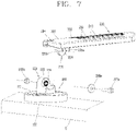
- FIG. 7 is a perspective view illustrating that a base and a bracket of the thermal image monitoring apparatus of FIG. 2 are coupled to each other.
- FIGS. 8 and 9 are perspective views illustrating that a bracket and a thermal image camera of the thermal image monitoring apparatus of FIG. 2 are coupled to each other.
- FIGS. 10A to 10C are exemplary views illustrating that a vibration reduction unit reduces vibration in accordance with one embodiment of the present disclosure.
- FIG. 11 is a rear view illustrating that a vibration reduction unit reduces vibration in accordance with another embodiment of the present disclosure.
- FIG. 1 is a lateral view illustrating an inside of a distributing panel in accordance with one embodiment of the present disclosure.
- a distributing panel includes a cabinet 1 , a fixing plate 5 , and a thermal image monitoring apparatus.
- the distributing panel includes a cabinet 1 defining an inner space S, a power component 2 disposed in the space S, a fixing plate 5 , and a thermal image monitoring apparatus installed on the fixing plate 5 to measure temperature of the power component 2 .
- the cabinet 1 may define appearance of the distributing panel and support power components disposed therein.
- the cabinet 1 may be configured by an assembly of a plurality of members.
- the cabinet 1 may include a frame 11 and side covers 13 covering the frame 11 .
- the cabinet 1 may include a frame 11 , a bottom part 15 , side covers 13 , and a top cover 16 disposed on a top.
- the distributing panel may further include doors 7 and 8 to open and close the space S.
- the doors 7 and 8 may include a front door 7 to open and close a front opening of the cabinet 1 , and a rear door 8 to open and close a rear opening of the cabinet 1 .
- the front door 7 and the rear door 8 may be disposed to be rotatable or slidable.
- the fixing plate 5 may be disposed horizontally on an inner side of the rear door 8 . That is, the fixing plate 5 may be provided in plurality disposed up and down in a spacing manner in a direction penetrating into the drawing or paper.
- the power component 2 which is disposed inside the cabinet 1 and of which temperature is measured by the thermal image monitoring apparatus may be a bus bar B, a capacitor (not illustrated), a reactor (not illustrated), a current transformer (CT), a circuit breaker (CB), or the like.
- the power component 2 of which temperature is to be measured by the thermal image monitoring apparatus may be a bus bar B.
- Objects of which temperatures are to be measured by the thermal image monitoring apparatus may be an R-phase bus bar, a T-phase bus bar, and an S-phase bus bar disposed in a sequential manner.
- the power component 2 of which temperature is to be measured by the thermal image monitoring apparatus may be a capacitor.
- Objects of which temperatures are to be measured by the thermal image monitoring apparatus may be an R-phase capacitor, a T-phase capacitor, and an S-phase capacitor disposed in a sequential manner.
- the power component 2 of which temperature is to be measured by the thermal image monitoring apparatus may be a reactor.
- Objects of which temperatures are to be measured by the thermal image monitoring apparatus may be an R-phase reactor, a T-phase reactor, and an S-phase reactor disposed in a sequential manner.
- the power component 2 of which temperature is to be measured by the thermal image monitoring apparatus may be a current transformer (CT).
- CT current transformer
- Objects of which temperatures are to be measured by the thermal image monitoring apparatus may be an R-phase current transformer, a T-phase current transformer, and an S-phase current transformer disposed in a sequential manner.
- the thermal image monitoring apparatus may measure temperatures of a plurality of power components of the same type, and also measure temperatures of a plurality of power components of different types.
- the distributing panel may have the same type of power components with similar temperature ranges, and one thermal image monitoring apparatus may measure temperatures of a plurality of power components which are the same in type and different in position.
- power component which is expected to have high temperature.
- power may be concentrated on a bus bar part, and it may be expected that the largest amount of heat is generated at the part.
- a user may dispose the thermal image monitoring apparatus toward the bus bar which is expected to generate heat the most.
- the user may install the thermal image monitoring apparatus on a fixing plate 5 , which is located at an appropriate height, among the fixing plates 5 spaced up and down from one another, so as to shine on a place to monitor.
- FIG. 2 is an exploded perspective view illustrating a thermal image monitoring apparatus in accordance with one embodiment of the present disclosure
- FIGS. 3 to 5 are views illustrating a configuration that the thermal image monitoring apparatus of FIG. 2 is rotatable centering on each axis.
- a thermal image monitoring apparatus includes a base 100 , a bracket 200 , and a thermal image camera 300 .
- a vibration reduction unit is disposed at least one of a position where the base 100 and the bracket 200 are coupled to each other, and a position where the bracket 200 and the thermal image camera 300 are coupled to each other.
- the base 100 is fixed to the fixing plate 5 disposed inside the distributing panel, as aforementioned.
- the fixing plate 5 is provided with a fixing plate hole 5 a .
- the base 100 is fixed to the fixing plate 5 by use of a coupling member 105 .
- the base 100 may include a base body 102 , a base protrusion coupling part 120 , and a coupling groove 110 .
- the base body 102 is formed to be disposed on the fixing plate 5 .
- the base body 102 may be formed in a circular shape to be rotatably coupled to the fixing plate 5 in a Z axis.
- the base protrusion coupling part 120 protrudes outward from the base body 102 .
- the base protrusion coupling part 120 protrudes opposite to a surface of the base body 102 facing the fixing plate 5 .
- the base protrusion coupling part 120 is formed to be coupled to the bracket 200 .
- the base body 102 may be provided with a coupling groove 110 formed to correspond to a circumferential shape.
- the coupling groove 110 is opened so that the coupling member 105 can be inserted.
- the coupling member 105 is inserted through the coupling groove 110 to be inserted into the fixing plate hole 5 a of the fixing plate 5 .
- the bracket 200 is coupled to the base 100 and is configured to adjust an angle forming with the base 100 .
- the bracket 200 may include a bracket body 202 that is curved or bent to be convex forward, and a bracket protrusion coupling part 220 protruding from a rear surface of the bracket body 202 to be coupled to the base protrusion coupling part 120 .
- the bracket body 202 may be provided with a plurality of slots 210 disposed in its lengthwise direction to be spaced apart from one another.
- the thermal image camera 300 may be fixed to the bracket 200 by coupling members 305 which are inserted through some of the plurality of slots 210 .
- Cable holes 204 through which a cable extending from the thermal image camera 300 is inserted may be formed at both ends of the bracket 200 .
- a cable for transferring information obtained by the thermal image camera 300 may be inserted into a terminal 306 of the thermal image camera 300 .
- the cable may be inserted into one of the cable holes 204 formed at the both ends of the bracket 200 , so as to be prevented from being suspended to the inside of the distributing panel.
- the cable can be arranged without regard to a direction that the thermal image camera 300 is installed on the bracket 200 .
- the thermal image camera 300 may be installed on the bracket 200 in different directions, other than a single direction.
- the thermal image camera 300 may be fixed to the bracket 200 in a horizontally long direction.
- the cable may be inserted into one of the cable holes 204 , which is located close to the terminal 306 of the thermal image camera 300 .
- the bracket body 202 may be provided with a bolt assembly hole 206 formed through the front surface thereof for coupling of the coupling member 105 .
- the base 102 is formed to be rotatable relative to the fixing plate 5 . If the coupling groove 110 of the base 102 is obscured by the bracket body 202 , it may make it difficult to assemble the coupling member 105 . In this case, the bolt assembly hole 206 may facilitate the coupling member 105 to be inserted into the coupling groove 110 .
- the bracket body 202 may be provided on its front surface with one surface 240 of a horizontal vibration reduction unit that is located between the plurality of slots 210 and brought into contact with one surface of the thermal image camera 300 to reduce vibration due to movement of the thermal image camera 300 . This will be described in detail later.
- the thermal image camera 300 may be provided with a body 302 , a camera module 304 disposed on a front surface 302 a of the body 302 , and a terminal 306 formed on a side surface of the body 302 for connection of a cable.
- the thermal image camera 300 has a rear surface 302 b coupled to the bracket 200 and is configured to adjust its facing direction according to a position at which it is coupled to the bracket 200 .
- the bracket 200 is formed long in up and down directions.
- the thermal image camera 300 may be disposed between an upper portion and a lower portion of the entire body of the bracket 200 which is long up and down. This may allow an installation height of the thermal image camera 300 to be adjustable.
- the front surface of the bracket body 202 may be bent or curved.
- the rear surface 302 b of the thermal image camera 300 may be fixed to the bracket 200 in contact with the bracket body 202 that is bent or curved.
- the thermal image camera 300 may be disposed on the front surface of the bracket body 202 according to a direction that the camera module 304 is to face.
- the thermal image camera 300 can be advantageously installed by setting an installation height and a facing direction.
- the vibration reduction unit reduces vibration which is transferred from the fixing plate 5 to the thermal image monitoring apparatus. Accordingly, the thermal image monitoring apparatus can be prevented from being separated from the fixing plate 5 or from a position where it shines on a power component to monitor.
- the vibration reduction unit may include a rotation-vibration reduction unit that reduces vibration due to rotation of the thermal image camera 300 and/or a horizontal vibration reduction unit that reduces vibration due to movement of the thermal image camera 300 to right and left. This will be described in detail later.
- the base 100 may be fixed by being rotated relative to the fixing plate 5 centering on one axis.
- the base 100 is rotatable relative to the fixing plate 5 centering on a Z axis.
- the fixing plate 5 may be provided with the fixing plate hole 5 a .
- the coupling groove 110 may be formed long in a circumferential direction of the base 100 . Therefore, even when the base 100 is rotated relative to the fixing plate 5 centering on the Z axis, the coupling member 105 can be inserted into the fixing plate hole 5 a through the coupling groove 110 .
- the bracket 200 may be fixed by being rotated relative to the base 100 centering on another axis perpendicular to the one axis. Specifically, referring to FIGS. 2 and 4 , the bracket 200 is rotatable with respect to the base 100 centering on the Z axis.
- the base protrusion coupling part 120 of the base 100 and the bracket protrusion coupling part 220 of the bracket 200 are coupled to each other.
- the base 100 and the bracket 200 are coupled to each other by a coupling member 205 .
- the coupling member 205 may include a bolt 205 a , a nut 205 b , a washer 205 c , and the like.
- a gap between the bracket 200 and the base 100 becomes narrow, and thereby a radius of rotation of the bracket 200 with respect to the base 100 centering on the X axis may be limited.
- the base protrusion coupling part 120 and the bracket protrusion coupling part 220 can be coupled by protruding from the base 100 and the bracket 200 , respectively, thereby defining a space in which the bracket 200 can be easily rotated with respect to the base 100 centering on the X axis.
- the thermal image camera 300 may be fixed by being rotated relative to the bracket 200 centering on an axis that is orthogonal to the one axis and the another axis. Specifically, referring to FIGS. 2 and 5 , the thermal image camera 300 is rotatable with respect to the bracket 200 , centering on a Y axis that is orthogonal to the X axis and the Z axis.
- the bracket body 202 is curved or bent to be convex forward. Accordingly, a direction that the thermal image camera 300 faces differs depending on a portion of the thermal image camera 300 which is brought into contact with the curved front surface of the bracket body 202 .
- the thermal image camera 300 when the thermal image camera 300 is brought into contact with a right portion of the front surface of the bracket body 202 , namely, a portion rotated (moved) from the center of the bracket body 202 centering on the X axis, the thermal image camera 300 is disposed to face a portion rotated counterclockwise centering on the Y axis.
- the thermal image camera 300 when the thermal image camera 300 is brought into contact with a left portion of the front surface of the bracket body 202 , namely, a portion rotated from the center of the bracket body 202 in a direction of a ⁇ X axis, the thermal image camera 300 is disposed to face a portion rotated clockwise center on the Y axis. That is, the direction that the thermal image camera 300 faces may be adjusted according to the curved front surface of the bracket body 202 .
- the thermal image monitoring apparatus can be fixed after being freely rotated relative to the fixing plate 5 centering on the three axes orthogonal to one another. As the degree of freedom of the position where the thermal image camera 300 is installed is increased, the thermal image monitoring apparatus can be easily adjusted in angle to face a power component to monitor.
- FIG. 6 is a perspective view illustrating that the fixing plate and the base of the thermal image monitoring apparatus of FIG. 2 are coupled to each other.
- FIG. 7 is a perspective view illustrating that the base and the bracket of the thermal image monitoring apparatus of FIG. 2 are coupled to each other.
- FIGS. 8 and 9 are perspective views illustrating that the bracket and the thermal image camera of the thermal image monitoring apparatus of FIG. 2 are coupled to each other.
- FIGS. 10A to 10C are exemplary views illustrating that a vibration reduction unit reduces vibration in accordance with one embodiment of the present disclosure.
- FIGS. 8 and 9 are diagrams viewed from different side surfaces for the sake of explanation.
- FIG. 8 is a right-top view
- FIG. 9 is a left-bottom view.
- the base 100 includes a base protrusion coupling part 120 protruding from the base body 102 to be coupled to the bracket 200 .
- the base protrusion coupling part 102 may include a round portion 122 , a one surface 123 of a rotation-vibration reduction unit to be explained later, and a rotation guide 126 .
- the round portion 122 may have a cross-section that an upper end is rounded and a lower end is gradually widened.
- a coupling hole 124 through which the coupling member 205 is inserted may be formed through a center of the round portion 122 .
- the coupling member 205 may be inserted through the coupling hole 124 so that the bracket 200 and the base protrusion coupling part 120 can be coupled to each other.
- the one surface 123 of the rotation-vibration reduction unit is defined on one side surface of the round portion 122 coupled with the bracket 200 .
- the one surface 123 of the rotation-vibration reduction unit constructs the rotation-vibration reduction unit by being coupled to another surface 223 of the rotation-vibration reduction unit to be explained later. That is, the rotation-vibration reduction unit includes the one surface 123 and the another surface 223 .
- the one surface 123 of the rotation-vibration reduction unit may be disposed to surround the coupling hole 124 . That is, the one surface 123 of the rotation-vibration reduction unit may be formed at the surrounding of the coupling hole 124 .
- the one surface 123 of the rotation-vibration reduction unit may have a concave-convex shape that is protruded or recessed repeatedly on a surface of the round portion 122 .
- the another surface 223 of the rotation-vibration reduction unit can be prevented from being slid.
- the contact between the one surface 123 of the rotation-vibration reduction unit and the another surface 223 of the rotation-vibration reduction unit can result in reducing vibration in a rotating direction.
- the rotation guide 126 protrudes from one side surface of the round portion 122 and has a curved surface in a circumferential shape that is convex downward.
- An upper end of the round portion 122 and the one surface 123 of the rotation-vibration reduction unit may have a cross-section approximately similar to a circle.
- the rotation guide 126 may protrude in an area corresponding to a lower end portion of a circumference of the circle.
- the rotation guide 126 defines a circumferential curved surface that is convex downward.
- Rotation protrusions 226 (see FIG. 9 ) of the bracket 200 are disposed adjacent to the surface of the rotation guide 126 .
- the rotation protrusions 226 of the bracket 200 may be rotated on the rotation guide 126 in such a slightly touching manner.
- the rotation protrusions 226 of the bracket 200 are rotated with slightly contacting the rotation guide 126 , the rotation protrusions 226 can be supported by the rotation guide 126 when the bracket 200 is moved up and down due to vibration, thereby reducing such up-and-down vibration.
- the coupling groove 110 of the base 100 may be provided by two that face each other.
- the coupling groove 110 may be provided by two to correspond to the number of fixing plate holes 5 a formed in the up-and-down direction of the fixing plate 5 .
- the coupling grooves 110 are preferably formed in a circumferential shape such that the coupling members 104 can be inserted into the fixing plate holes 5 a even though the base 100 is rotated.
- the two coupling grooves 110 facing each other are formed in the circumferential shape so that the coupling members 105 can be inserted into the fixing plate holes 5 a even though the base is rotated.
- the coupling member 105 may be a bolt, and a bolt head 105 a formed on an upper end of the bolt 105 may be caught on the stopping jaw 112 .
- bracket 200 will be described with reference to FIGS. 8 and 9 .
- the bracket 200 may include a bracket body 202 bent to be convex forward. Specifically, the bracket body 202 may be bent or curved to be convex to an opposite side of the base 100 .
- the bracket body 202 which is convex forward is brought into contact with a concave portion 310 formed on the rear surface 302 b of the thermal image camera 300 , to stably support the thermal image camera 300 .
- the bracket body 202 is bent to be convex, like a part of a circumference, so as to adjust the direction that the thermal image camera 300 faces according to the position where the thermal image camera 300 is disposed, as aforementioned.
- the bracket protrusion coupling part 220 protrudes from the rear surface of the bracket body 202 to be coupled to the base protrusion coupling part 120 .
- the bracket protrusion coupling part 220 may include a round portion coupling part 222 , another surface 223 of the rotation-vibration reduction unit, and rotating protrusions 226 .
- the round portion coupling part 222 is provided with an opening 224 that communicates with the coupling hole 124 upon coupling with the round portion 122 of the base 100 .
- the round portion 122 and the round portion coupling part 221 may be coupled after being rotated relative to each other. Accordingly, the round portion coupling part 221 is preferably formed in a shape similar to the circle at the circular lower end of the round portion 122 of the base 100 .
- the another surface 223 of the rotation-vibration reduction unit 223 is located on one side surface of the round portion coupling part 222 .
- the another surface of the rotation-vibration reduction unit 223 is formed on a surface of the round portion coupling part 222 , which faces the one surface 123 of the rotation-vibration reduction unit when the round portion coupling part 222 is coupled to the round portion 122 of the base 100 .
- the another surface 223 of the rotation-vibration reduction unit may be brought into contact with the one surface 123 of the rotation-vibration reduction unit of the base 100 so as to reduce vibration due to the rotation of the bracket 200 .
- at least one of the one surface 123 and the another surface 223 of the rotation-vibration reduction unit may be provided with a concave-convex pattern that is repeatedly protruded and recessed.
- one of the one surface 123 and the another surface 223 of the rotation-vibration reduction unit may be made of an elastic material and the other may have the concave-convex shape. Accordingly, when the surface formed of the elastic material is coupled to the portion (the surface) with the concave-convex shape through the coupling member 205 , the surface formed of the elastic material may be deformed due to a convex (protruded) portion of the surface in the concave-convex shape.
- the one surface 123 and the another surface of the rotation-vibration reduction unit can be strongly coupled to each other, which may result in reducing deformation and shaking due to vibration.
- the rotation-vibration reduction unit can reduce relative rotation between the base protrusion coupling part 120 and the bracket protrusion coupling part 220 . This may result in preventing the change of an initially-set angle between the base 100 and the bracket 200 which is caused due to vibration.
- both of the one surface 123 and the another surface 223 of the rotation-vibration unit may have concave-convex portions, respectively.
- the rotation protrusions 226 protrude to another side of the round portion coupling part 222 .
- the rotation protrusions 226 may protrude opposite to a surface of the round portion coupling part 222 where the another surface 223 of the rotation-vibration reduction unit is defined.
- the rotation protrusions 226 may be located at a position corresponding to the rotation guide 126 of the base 100 .
- the rotation protrusions 226 can rotate in the vicinity of the rotation guide 126 when the bracket 200 rotates relative to the base 100 centering on one axis.
- the rotation protrusions 226 may be disposed at both sides to face each other. Therefore, when the bracket 200 rotates relative to the base 100 , one of the rotation protrusions 226 may be disposed close to the rotation guide 126 .
- a first rotation protrusion 226 a rotates to be at an inner side of the rotation guide 126
- a second rotation protrusion 226 b rotates to be at an outer side of the rotation guide 126 .
- one of the rotation guides 226 disposed at both sides to face each other may be brought into contact with the rotation guide 126 , thereby guiding the rotation of the bracket.
- the rotation protrusions 226 can support the rotation guide 126 , thereby reducing the vibration.
- bracket 200 and the thermal image camera 300 will be described with reference to FIGS. 8 and 9 .
- One surface 240 of a horizontal vibration reduction unit may be defined on a front surface of the bracket body 202 .
- the one surface 240 of the horizontal vibration reduction unit is defined between the plurality of slots 210 .
- the one surface 240 of the horizontal vibration reduction unit may be brought into contact with one surface of the thermal image camera 300 to reduce vibration due to movement of the thermal image camera 300 .
- the one surface of the horizontal vibration reduction unit may have a concave-convex shape that is protruded and recessed repeatedly, and may be formed in the same direction as a lengthwise direction of the bracket 200 .
- the one surface 240 of the horizontal vibration reduction unit may have the concave-convex shape in the same direction as the lengthwise direction of the bracket 200 .
- the thermal image camera 300 may be fixed to the bracket 200 through at least one thermal image camera coupling member 305 , which is inserted through at least one of the plurality of slots 210 , so that its mounted position to the bracket 200 can change.
- the at least one coupling member 305 which is inserted through the at least one of the plurality of slots 210 is coupled to at least one coupling hole 320 h that is formed on a rear surface of the thermal image camera body 302 . Accordingly, the bracket 200 and the thermal image camera 300 can be fixed to each other.
- the rear surface of the thermal image camera 300 may include concave portions 310 that are recessed inward to correspond to the bracket body 202 that is curved to be convex forward.
- the concave portion 310 may be recessed to correspond to the front surface of the bracket body 202 . That is, a degree that the concave portion 310 is concave or recessed corresponds to a degree that the front surface of the bracket body 202 is curved or bent. Accordingly, the rear surface of the thermal image camera 300 and the front surface of the bracket 200 can overlap each other and each concave portion 310 can be entirely brought into contact with the bracket body 202 .
- the concave portion 310 may be formed in the lengthwise direction of the bracket body 202 and provided by two or more so as to intersect with each other. As illustrated in FIG. 9 , a first concave portion 310 a may be formed long in a vertical direction of the thermal image camera 300 and a second concave portion 310 b may perpendicularly intersect with the first concave portion 310 a.
- the first concave portion 310 a may be disposed vertically to be in contact with the bracket body 202
- the second concave portion 310 b may be disposed horizontally to be in contact with the bracket body 202 .
- Each concave portion 310 may be provided with another surface 320 of the horizontal vibration reduction unit that is brought into contact with the one surface 240 of the horizontal vibration reduction unit of the bracket 200 so as to reduce vibration in one direction.
- the one surface 240 of the horizontal vibration reduction unit defined on the front surface of the bracket body 202 can be coupled with the another surface 320 of the horizontal vibration reduction unit formed around the coupling hole 320 a of the concave portion 310 formed on the rear surface of the thermal image camera body 302 .
- Pressing force between the bracket 200 and the thermal image camera 300 may concentrate on the surrounding of the coupling hole 320 a by the coupling member 305 . Since the another surface 320 of the horizontal vibration reduction unit is formed on the surrounding of the coupling hole 320 a on which the pressing force concentrates, the effect of reducing vibration in a horizontal direction can increase.
- the one surface 240 and the another surface 320 of the horizontal vibration reduction unit are spaced apart from each other.
- Each of the one surface 240 and the another surface 320 of the horizontal vibration reduction unit may have the concave-convex shape.
- the one surface 240 of the horizontal vibration reduction unit may have protruding portions 241 and recess portions 242 that are repeatedly formed.
- the another surface 320 of the horizontal vibration reduction unit may also have protruding portions 321 and recess portions 322 that are repeatedly formed.
- the one surface 240 and the another surface 320 of the horizontal vibration reduction unit are disposed close to each other.
- the protruding portions 241 of the one surface 240 of the horizontal vibration reduction unit may overlap the protruding portions 321 of the another surface of the horizontal vibration reduction unit. This is a state in which the thermal image camera 300 and the bracket body 202 are not completely coupled to each other yet.
- the one surface 240 and the another surface of the horizontal vibration reduction unit are completely coupled to each other so that the concave-convex shapes are engaged with each other.
- the one surface 240 and the another surface 320 of the horizontal vibration reduction unit may be in contact with each other in the state as illustrated in FIG. 10B .
- one of the one surface 240 and the another surface of the horizontal vibration reduction unit may be moved to be in the state as illustrated in FIG. 10C .
- the movement of the thermal image camera 300 to right and left is limited.
- vibration that is transferred from the bracket 200 to the thermal image camera 300 can be reduced. This may also result in reducing unintended movement of the thermal image camera 300 which may be caused as the coupling between the bracket 200 and the thermal image camera 300 is loosed due to vibration of a distributing panel.
- the coupling between the concave-convex portions may equally be made between the one surface 123 and the another surface 223 of the rotation-vibration reduction unit.
- one surface of each of the rotation-vibration reduction unit and the horizontal vibration reduction unit may be elastically flat and another surface may have a concave-convex shape.
- the protruding portions 241 and 321 of the one surface 240 and the another surface 320 of the horizontal vibration reduction unit may have lengths shorter than those of the recess portions 242 and 322 .
- a space or gap may be formed in each recess portion 242 and 322 when the front surface of the bracket body 202 and the concave portions 310 of the thermal image camera 300 overlap each other. Therefore, the coupling member 305 can couple the bracket body 202 and the thermal image camera 300 while causing a slight elastic deformation due to the space formed in each recess portion 242 and 322 .
- the another surface 320 of the horizontal vibration reduction unit may also be formed on another portion of the concave portion 310 in addition to the surrounding of the coupling hole 320 h of the concave portion 310 .
- the another surface 320 of the horizontal vibration reduction unit may be formed in an area except for an area where the first concave portion 310 a and the second concave portion 310 b overlap each other.
- the one surface 240 and the another surface 320 of the horizontal vibration reduction unit can be brought into contact with each other at a larger area, thereby further increasing the coupling force between the bracket 200 and the thermal image camera 300 .
- FIG. 11 is a rear view illustrating a thermal image camera in accordance with another embodiment of the present disclosure.
- a thermal image camera 300 ′ illustrated in FIG. 11 have the same or similar components to those of the thermal image camera 300 illustrated in FIG. 9 except for a shape of a concave portion 310 ′. Therefore, description of those similar components will be omitted.
- concave portions 310 ′ of the thermal image camera 300 ′ may be formed at four places.
- a first concave portion 310 a ′, a second concave portion 310 b ′, a third concave portion 310 c ′, and a fourth concave portion 310 d ′ may intersect with one another at about 45 degrees.
- Another surface 320 ′ of a horizontal vibration reduction unit is disposed on each concave portion 310 ′.
- the number of directions that the thermal image camera 300 ′ can be arranged when mounted to the bracket can increase. This may allow a user to arrange the thermal image camera 300 ′ to shine on a power component to monitor within a distributing panel more accurately.
Landscapes
- Engineering & Computer Science (AREA)
- Multimedia (AREA)
- Signal Processing (AREA)
- Toxicology (AREA)
- Health & Medical Sciences (AREA)
- Physics & Mathematics (AREA)
- General Engineering & Computer Science (AREA)
- Power Engineering (AREA)
- General Physics & Mathematics (AREA)
- Mechanical Engineering (AREA)
- Aviation & Aerospace Engineering (AREA)
- Acoustics & Sound (AREA)
- Spectroscopy & Molecular Physics (AREA)
- Emergency Management (AREA)
- Business, Economics & Management (AREA)
- Studio Devices (AREA)
- Radiation Pyrometers (AREA)
- Accessories Of Cameras (AREA)
Abstract
Description
Claims (17)
Applications Claiming Priority (2)
| Application Number | Priority Date | Filing Date | Title |
|---|---|---|---|
| KR10-2019-0152576 | 2019-11-25 | ||
| KR1020190152576A KR102293002B1 (en) | 2019-11-25 | 2019-11-25 | Thermal image monitoring apparatus and distributing panel having the same |
Publications (2)
| Publication Number | Publication Date |
|---|---|
| US20210160428A1 US20210160428A1 (en) | 2021-05-27 |
| US11310429B2 true US11310429B2 (en) | 2022-04-19 |
Family
ID=75923088
Family Applications (1)
| Application Number | Title | Priority Date | Filing Date |
|---|---|---|---|
| US16/857,709 Active US11310429B2 (en) | 2019-11-25 | 2020-04-24 | Thermal image monitoring apparatus and distributing panel having the same |
Country Status (4)
| Country | Link |
|---|---|
| US (1) | US11310429B2 (en) |
| JP (1) | JP7185658B2 (en) |
| KR (1) | KR102293002B1 (en) |
| CN (1) | CN112837496B (en) |
Citations (28)
| Publication number | Priority date | Publication date | Assignee | Title |
|---|---|---|---|---|
| JPH04315930A (en) | 1991-04-16 | 1992-11-06 | Minolta Camera Co Ltd | Temperature monitoring device |
| JPH05212664A (en) | 1992-02-03 | 1993-08-24 | Hitachi Constr Mach Co Ltd | Vibro-isolating mechanism for grinder operation of robot |
| JP2001103454A (en) | 1999-10-01 | 2001-04-13 | Daiko Electric Co Ltd | Lighting device and monitoring device using the lighting device |
| JP2002131830A (en) | 2000-10-25 | 2002-05-09 | Inc Engineering Co Ltd | Bird's-eye view shooting camera panhead |
| JP2002354306A (en) | 2001-05-22 | 2002-12-06 | Sony Computer Entertainment Inc | Imaging device |
| US20030103160A1 (en) * | 2001-12-05 | 2003-06-05 | Toshikazu Tatewaki | Surveillance camera with impact absorbing structure |
| US20040017167A1 (en) * | 2002-07-26 | 2004-01-29 | Nikon Corporation | Vibration control device, stage device and exposure apparatus |
| CN1917583A (en) | 2005-08-19 | 2007-02-21 | 株式会社东芝 | Camera device |
| KR101260709B1 (en) | 2012-02-08 | 2013-05-15 | 주식회사 웍스웰테크 | Cctv bracket |
| US20140168433A1 (en) * | 2009-06-03 | 2014-06-19 | Flir Systems, Inc. | Systems and methods for monitoring power systems |
| US20150097950A1 (en) * | 2013-10-08 | 2015-04-09 | SZ DJI Technology Co., Ltd. | Apparatus and methods for stabilization and vibration reduction |
| US20160020650A1 (en) * | 2014-07-17 | 2016-01-21 | Flir Systems, Inc. | Powered security camera tool-free installation |
| JP2016038277A (en) | 2014-08-07 | 2016-03-22 | 株式会社東光高岳 | Electrical facility temperature monitoring device and electrical facility temperature monitoring system |
| US20160083110A1 (en) * | 2014-04-28 | 2016-03-24 | SZ DJI Technology Co., Ltd. | Interchangeable mounting platform |
| CN205647693U (en) | 2016-03-14 | 2016-10-12 | 浙江大华技术股份有限公司 | Thermal imaging camera |
| KR101700183B1 (en) | 2016-09-07 | 2017-02-13 | 주식회사 광명전기 | apparatus for watching electric equipments of switch gear |
| US20170195584A1 (en) * | 2014-09-23 | 2017-07-06 | Flir Systems, Inc. | Modular split-processing infrared imaging system |
| CN106973201A (en) | 2017-03-07 | 2017-07-21 | 杨志强 | A kind of double vision monitoring device |
| JP2017184306A (en) | 2016-03-28 | 2017-10-05 | キヤノン株式会社 | Slewing drive |
| US9835934B2 (en) * | 2014-12-12 | 2017-12-05 | Chips Unlimited, Inc. | Systems and methods for mounting photographic equipment |
| US20170363932A1 (en) * | 2016-06-17 | 2017-12-21 | Hanwha Techwin Co., Ltd. | Security camera system |
| KR20180063602A (en) | 2016-12-02 | 2018-06-12 | 주식회사 대경산전 | Seismic switchgear equipped with shock absorber having crista structure |
| KR101903342B1 (en) | 2018-05-08 | 2018-10-11 | 주식회사 이티씨 | Fire prevnetion device using thermal image and control panel |
| CN109000803A (en) | 2018-07-30 | 2018-12-14 | 袁茂银 | A kind of high-tension switch cabinet thermal imaging monitoring device |
| US20190035588A1 (en) * | 2017-07-27 | 2019-01-31 | Lsis Co., Ltd. | Direct current air circuit breaker |
| KR20190036063A (en) | 2017-09-27 | 2019-04-04 | 엘에스산전 주식회사 | Protection relay having thermal imaging camera |
| US20190215423A1 (en) * | 2018-01-08 | 2019-07-11 | TP-Link Research America Corp. | Security monitoring system |
| US20190308563A1 (en) * | 2016-07-20 | 2019-10-10 | Nifco Inc. | Camera unit |
Family Cites Families (2)
| Publication number | Priority date | Publication date | Assignee | Title |
|---|---|---|---|---|
| CN206181253U (en) * | 2016-11-10 | 2017-05-17 | 深圳市誉满鑫科技有限公司 | Detachable wireless long -distance formula video monitor |
| CN207163563U (en) * | 2017-09-18 | 2018-03-30 | 浙江国自机器人技术有限公司 | A kind of contactless vibration detection device |
-
2019
- 2019-11-25 KR KR1020190152576A patent/KR102293002B1/en active Active
-
2020
- 2020-04-22 JP JP2020076017A patent/JP7185658B2/en active Active
- 2020-04-24 US US16/857,709 patent/US11310429B2/en active Active
- 2020-04-24 CN CN202010332802.8A patent/CN112837496B/en active Active
Patent Citations (29)
| Publication number | Priority date | Publication date | Assignee | Title |
|---|---|---|---|---|
| JPH04315930A (en) | 1991-04-16 | 1992-11-06 | Minolta Camera Co Ltd | Temperature monitoring device |
| JPH05212664A (en) | 1992-02-03 | 1993-08-24 | Hitachi Constr Mach Co Ltd | Vibro-isolating mechanism for grinder operation of robot |
| JP2001103454A (en) | 1999-10-01 | 2001-04-13 | Daiko Electric Co Ltd | Lighting device and monitoring device using the lighting device |
| JP2002131830A (en) | 2000-10-25 | 2002-05-09 | Inc Engineering Co Ltd | Bird's-eye view shooting camera panhead |
| JP2002354306A (en) | 2001-05-22 | 2002-12-06 | Sony Computer Entertainment Inc | Imaging device |
| US20030103160A1 (en) * | 2001-12-05 | 2003-06-05 | Toshikazu Tatewaki | Surveillance camera with impact absorbing structure |
| US20040017167A1 (en) * | 2002-07-26 | 2004-01-29 | Nikon Corporation | Vibration control device, stage device and exposure apparatus |
| CN1917583A (en) | 2005-08-19 | 2007-02-21 | 株式会社东芝 | Camera device |
| US20140168433A1 (en) * | 2009-06-03 | 2014-06-19 | Flir Systems, Inc. | Systems and methods for monitoring power systems |
| KR101260709B1 (en) | 2012-02-08 | 2013-05-15 | 주식회사 웍스웰테크 | Cctv bracket |
| US20150097950A1 (en) * | 2013-10-08 | 2015-04-09 | SZ DJI Technology Co., Ltd. | Apparatus and methods for stabilization and vibration reduction |
| US20160083110A1 (en) * | 2014-04-28 | 2016-03-24 | SZ DJI Technology Co., Ltd. | Interchangeable mounting platform |
| CN106471337A (en) | 2014-04-28 | 2017-03-01 | 深圳市大疆创新科技有限公司 | Alternative Mounting Platforms |
| US20160020650A1 (en) * | 2014-07-17 | 2016-01-21 | Flir Systems, Inc. | Powered security camera tool-free installation |
| JP2016038277A (en) | 2014-08-07 | 2016-03-22 | 株式会社東光高岳 | Electrical facility temperature monitoring device and electrical facility temperature monitoring system |
| US20170195584A1 (en) * | 2014-09-23 | 2017-07-06 | Flir Systems, Inc. | Modular split-processing infrared imaging system |
| US9835934B2 (en) * | 2014-12-12 | 2017-12-05 | Chips Unlimited, Inc. | Systems and methods for mounting photographic equipment |
| CN205647693U (en) | 2016-03-14 | 2016-10-12 | 浙江大华技术股份有限公司 | Thermal imaging camera |
| JP2017184306A (en) | 2016-03-28 | 2017-10-05 | キヤノン株式会社 | Slewing drive |
| US20170363932A1 (en) * | 2016-06-17 | 2017-12-21 | Hanwha Techwin Co., Ltd. | Security camera system |
| US20190308563A1 (en) * | 2016-07-20 | 2019-10-10 | Nifco Inc. | Camera unit |
| KR101700183B1 (en) | 2016-09-07 | 2017-02-13 | 주식회사 광명전기 | apparatus for watching electric equipments of switch gear |
| KR20180063602A (en) | 2016-12-02 | 2018-06-12 | 주식회사 대경산전 | Seismic switchgear equipped with shock absorber having crista structure |
| CN106973201A (en) | 2017-03-07 | 2017-07-21 | 杨志强 | A kind of double vision monitoring device |
| US20190035588A1 (en) * | 2017-07-27 | 2019-01-31 | Lsis Co., Ltd. | Direct current air circuit breaker |
| KR20190036063A (en) | 2017-09-27 | 2019-04-04 | 엘에스산전 주식회사 | Protection relay having thermal imaging camera |
| US20190215423A1 (en) * | 2018-01-08 | 2019-07-11 | TP-Link Research America Corp. | Security monitoring system |
| KR101903342B1 (en) | 2018-05-08 | 2018-10-11 | 주식회사 이티씨 | Fire prevnetion device using thermal image and control panel |
| CN109000803A (en) | 2018-07-30 | 2018-12-14 | 袁茂银 | A kind of high-tension switch cabinet thermal imaging monitoring device |
Non-Patent Citations (4)
| Title |
|---|
| Chinese Office Action for related Chinese Application No. 202010332802.8; action dated Feb. 25, 2022; (10 pages). |
| Japanese Office Action for related Japanese Application No. 2020-076017; action dated Jun. 8, 2021; (6 pages). |
| Korean Notice of Allowance for related Korean Application No. 10-2019-0152576; action dated Aug. 12, 2021; (2 pages). |
| Korean Office Action for related Korean Application No. 10-2019-0152576; action dated Feb. 22, 2021; (5 pages). |
Also Published As
| Publication number | Publication date |
|---|---|
| KR20210063910A (en) | 2021-06-02 |
| JP2021085868A (en) | 2021-06-03 |
| KR102293002B1 (en) | 2021-08-24 |
| CN112837496A (en) | 2021-05-25 |
| US20210160428A1 (en) | 2021-05-27 |
| CN112837496B (en) | 2023-08-08 |
| JP7185658B2 (en) | 2022-12-07 |
Similar Documents
| Publication | Publication Date | Title |
|---|---|---|
| JP7424569B2 (en) | foldable screen device | |
| US10700501B2 (en) | Adjustable mud ring assembly | |
| US9842712B2 (en) | Switching device having terminal cover, and method | |
| US12334679B2 (en) | Connection unit, connection arrangement and electronic device | |
| US20050263313A1 (en) | Sixplex receptacle | |
| CA2967686C (en) | Power contacting device | |
| US10135209B1 (en) | Busway stab assemblies and related systems and methods | |
| CN104425971B (en) | Connector device with locking element and connector used for the connector device | |
| US11310429B2 (en) | Thermal image monitoring apparatus and distributing panel having the same | |
| US6433999B1 (en) | Bus connection access panel | |
| GB2523476A (en) | Closing acknowledgement device for elevator | |
| CN108779910B (en) | Electronic device for installation in a switchgear cabinet, having a first and a second fastening element | |
| US11557845B2 (en) | Modular plug-in connector system | |
| CN107454814B (en) | Electric shell | |
| JP2017085690A (en) | Electric wire guide | |
| US10069286B2 (en) | Insulation structure for splice portion, harness mounting plate, and wiring unit | |
| TW406452B (en) | Coaxial cable connector | |
| KR20170106728A (en) | A Stopper hinge for heavy equipment | |
| JP2007149629A (en) | Quick-connection terminal device and wiring fixture | |
| JP2603184B2 (en) | Combination of plug and outlet to prevent rattling | |
| JP2025167382A (en) | Wiring device case and wiring device device | |
| JP6416557B2 (en) | connector | |
| JP2025167383A (en) | Wiring device case and wiring device device | |
| JP2520519B2 (en) | Neutral switch | |
| CN206727353U (en) | A kind of safety socket |
Legal Events
| Date | Code | Title | Description |
|---|---|---|---|
| FEPP | Fee payment procedure |
Free format text: ENTITY STATUS SET TO UNDISCOUNTED (ORIGINAL EVENT CODE: BIG.); ENTITY STATUS OF PATENT OWNER: LARGE ENTITY |
|
| AS | Assignment |
Owner name: LS ELECTRIC CO., LTD., KOREA, REPUBLIC OF Free format text: ASSIGNMENT OF ASSIGNORS INTEREST;ASSIGNOR:YANG, SEUNGPIL;REEL/FRAME:052637/0473 Effective date: 20200403 |
|
| STPP | Information on status: patent application and granting procedure in general |
Free format text: RESPONSE TO NON-FINAL OFFICE ACTION ENTERED AND FORWARDED TO EXAMINER |
|
| STPP | Information on status: patent application and granting procedure in general |
Free format text: NON FINAL ACTION MAILED |
|
| STPP | Information on status: patent application and granting procedure in general |
Free format text: RESPONSE TO NON-FINAL OFFICE ACTION ENTERED AND FORWARDED TO EXAMINER |
|
| STPP | Information on status: patent application and granting procedure in general |
Free format text: WITHDRAW FROM ISSUE AWAITING ACTION |
|
| STPP | Information on status: patent application and granting procedure in general |
Free format text: AWAITING TC RESP., ISSUE FEE NOT PAID |
|
| STPP | Information on status: patent application and granting procedure in general |
Free format text: NOTICE OF ALLOWANCE MAILED -- APPLICATION RECEIVED IN OFFICE OF PUBLICATIONS |
|
| STPP | Information on status: patent application and granting procedure in general |
Free format text: PUBLICATIONS -- ISSUE FEE PAYMENT VERIFIED |
|
| STCF | Information on status: patent grant |
Free format text: PATENTED CASE |
|
| MAFP | Maintenance fee payment |
Free format text: PAYMENT OF MAINTENANCE FEE, 4TH YEAR, LARGE ENTITY (ORIGINAL EVENT CODE: M1551); ENTITY STATUS OF PATENT OWNER: LARGE ENTITY Year of fee payment: 4 |