US11310058B2 - Methods for digitally signing an electronic file and authentication method - Google Patents
Methods for digitally signing an electronic file and authentication method Download PDFInfo
- Publication number
- US11310058B2 US11310058B2 US16/734,500 US202016734500A US11310058B2 US 11310058 B2 US11310058 B2 US 11310058B2 US 202016734500 A US202016734500 A US 202016734500A US 11310058 B2 US11310058 B2 US 11310058B2
- Authority
- US
- United States
- Prior art keywords
- server
- generating
- electronic file
- biometric data
- data
- Prior art date
- Legal status (The legal status is an assumption and is not a legal conclusion. Google has not performed a legal analysis and makes no representation as to the accuracy of the status listed.)
- Active
Links
- 238000000034 method Methods 0.000 title claims abstract description 73
- 238000012795 verification Methods 0.000 claims abstract description 30
- 238000004891 communication Methods 0.000 claims abstract description 29
- 230000008569 process Effects 0.000 claims description 21
- 238000013507 mapping Methods 0.000 claims description 5
- 238000013500 data storage Methods 0.000 description 21
- 230000009467 reduction Effects 0.000 description 18
- 238000013528 artificial neural network Methods 0.000 description 15
- 230000006870 function Effects 0.000 description 12
- 238000010586 diagram Methods 0.000 description 10
- 230000003068 static effect Effects 0.000 description 6
- 230000001133 acceleration Effects 0.000 description 5
- 230000008901 benefit Effects 0.000 description 4
- 230000009466 transformation Effects 0.000 description 4
- 230000002093 peripheral effect Effects 0.000 description 3
- 238000012545 processing Methods 0.000 description 3
- 239000013598 vector Substances 0.000 description 3
- 230000008859 change Effects 0.000 description 2
- 238000005516 engineering process Methods 0.000 description 2
- 230000004048 modification Effects 0.000 description 2
- 238000012986 modification Methods 0.000 description 2
- 230000003287 optical effect Effects 0.000 description 2
- 210000003462 vein Anatomy 0.000 description 2
- 230000002776 aggregation Effects 0.000 description 1
- 238000004220 aggregation Methods 0.000 description 1
- 238000013459 approach Methods 0.000 description 1
- 230000037237 body shape Effects 0.000 description 1
- 230000001419 dependent effect Effects 0.000 description 1
- 230000000694 effects Effects 0.000 description 1
- 230000004424 eye movement Effects 0.000 description 1
- 238000007726 management method Methods 0.000 description 1
- 238000004806 packaging method and process Methods 0.000 description 1
- 238000003825 pressing Methods 0.000 description 1
- 238000011946 reduction process Methods 0.000 description 1
- 230000000717 retained effect Effects 0.000 description 1
- 238000005070 sampling Methods 0.000 description 1
- 238000003860 storage Methods 0.000 description 1
- 230000002123 temporal effect Effects 0.000 description 1
- 230000000007 visual effect Effects 0.000 description 1
Images


Classifications
-
- H—ELECTRICITY
- H04—ELECTRIC COMMUNICATION TECHNIQUE
- H04L—TRANSMISSION OF DIGITAL INFORMATION, e.g. TELEGRAPHIC COMMUNICATION
- H04L9/00—Cryptographic mechanisms or cryptographic arrangements for secret or secure communications; Network security protocols
- H04L9/32—Cryptographic mechanisms or cryptographic arrangements for secret or secure communications; Network security protocols including means for verifying the identity or authority of a user of the system or for message authentication, e.g. authorization, entity authentication, data integrity or data verification, non-repudiation, key authentication or verification of credentials
- H04L9/3247—Cryptographic mechanisms or cryptographic arrangements for secret or secure communications; Network security protocols including means for verifying the identity or authority of a user of the system or for message authentication, e.g. authorization, entity authentication, data integrity or data verification, non-repudiation, key authentication or verification of credentials involving digital signatures
-
- G—PHYSICS
- G06—COMPUTING; CALCULATING OR COUNTING
- G06F—ELECTRIC DIGITAL DATA PROCESSING
- G06F21/00—Security arrangements for protecting computers, components thereof, programs or data against unauthorised activity
- G06F21/30—Authentication, i.e. establishing the identity or authorisation of security principals
- G06F21/31—User authentication
- G06F21/32—User authentication using biometric data, e.g. fingerprints, iris scans or voiceprints
-
- G—PHYSICS
- G06—COMPUTING; CALCULATING OR COUNTING
- G06F—ELECTRIC DIGITAL DATA PROCESSING
- G06F21/00—Security arrangements for protecting computers, components thereof, programs or data against unauthorised activity
- G06F21/60—Protecting data
- G06F21/62—Protecting access to data via a platform, e.g. using keys or access control rules
- G06F21/6218—Protecting access to data via a platform, e.g. using keys or access control rules to a system of files or objects, e.g. local or distributed file system or database
- G06F21/6272—Protecting access to data via a platform, e.g. using keys or access control rules to a system of files or objects, e.g. local or distributed file system or database by registering files or documents with a third party
-
- G—PHYSICS
- G06—COMPUTING; CALCULATING OR COUNTING
- G06F—ELECTRIC DIGITAL DATA PROCESSING
- G06F21/00—Security arrangements for protecting computers, components thereof, programs or data against unauthorised activity
- G06F21/60—Protecting data
- G06F21/64—Protecting data integrity, e.g. using checksums, certificates or signatures
-
- H—ELECTRICITY
- H04—ELECTRIC COMMUNICATION TECHNIQUE
- H04L—TRANSMISSION OF DIGITAL INFORMATION, e.g. TELEGRAPHIC COMMUNICATION
- H04L63/00—Network architectures or network communication protocols for network security
- H04L63/08—Network architectures or network communication protocols for network security for authentication of entities
- H04L63/0861—Network architectures or network communication protocols for network security for authentication of entities using biometrical features, e.g. fingerprint, retina-scan
-
- H—ELECTRICITY
- H04—ELECTRIC COMMUNICATION TECHNIQUE
- H04L—TRANSMISSION OF DIGITAL INFORMATION, e.g. TELEGRAPHIC COMMUNICATION
- H04L9/00—Cryptographic mechanisms or cryptographic arrangements for secret or secure communications; Network security protocols
- H04L9/06—Cryptographic mechanisms or cryptographic arrangements for secret or secure communications; Network security protocols the encryption apparatus using shift registers or memories for block-wise or stream coding, e.g. DES systems or RC4; Hash functions; Pseudorandom sequence generators
- H04L9/0643—Hash functions, e.g. MD5, SHA, HMAC or f9 MAC
-
- H—ELECTRICITY
- H04—ELECTRIC COMMUNICATION TECHNIQUE
- H04L—TRANSMISSION OF DIGITAL INFORMATION, e.g. TELEGRAPHIC COMMUNICATION
- H04L9/00—Cryptographic mechanisms or cryptographic arrangements for secret or secure communications; Network security protocols
- H04L9/32—Cryptographic mechanisms or cryptographic arrangements for secret or secure communications; Network security protocols including means for verifying the identity or authority of a user of the system or for message authentication, e.g. authorization, entity authentication, data integrity or data verification, non-repudiation, key authentication or verification of credentials
- H04L9/3263—Cryptographic mechanisms or cryptographic arrangements for secret or secure communications; Network security protocols including means for verifying the identity or authority of a user of the system or for message authentication, e.g. authorization, entity authentication, data integrity or data verification, non-repudiation, key authentication or verification of credentials involving certificates, e.g. public key certificate [PKC] or attribute certificate [AC]; Public key infrastructure [PKI] arrangements
- H04L9/3268—Cryptographic mechanisms or cryptographic arrangements for secret or secure communications; Network security protocols including means for verifying the identity or authority of a user of the system or for message authentication, e.g. authorization, entity authentication, data integrity or data verification, non-repudiation, key authentication or verification of credentials involving certificates, e.g. public key certificate [PKC] or attribute certificate [AC]; Public key infrastructure [PKI] arrangements using certificate validation, registration, distribution or revocation, e.g. certificate revocation list [CRL]
Definitions
- the invention relates to methods for digitally signing an electronic file and to a biometrics-based authentication method.
- U.S. Pat. No. 6,735,695 B1 a solution is disclosed wherein authentication is performed using only a portion of biometric data rather than the entire biometric sample. For enhanced security it is thereby provided that the full biometric sample is not transmitted.
- the partial biometric sample applied for authentication can also be selected using a random number.
- a disadvantage of this known solution is that data reduction (transformation) is not carried out, and thus by eavesdropping on the communication lines for partial biometrics unauthorised persons may sooner or later capture the full biometric information.
- a further disadvantage of the solution is that the biometric sensor records the full biometric sample, and the partial biometrics are selected from the full sample. Recording the full biometric sample constitutes a significant vulnerability.
- U.S. Patent Application Publication No. 2008/0209227 A1 discloses a solution wherein a transformed, reduced version of the biometric sample is generated.
- the reduced biometric data or reduced biometric digest may contain different characteristic features of the biometric sample, such as its linear sections.
- U.S. Patent Application Publication No. 2010/0066493 A1 a solution related to a random projection transform of biometric data is disclosed.
- the object of the invention is to provide methods for digital signing and for authentication that eliminate the drawbacks of prior art solutions to the greatest possible extent.
- FIG. 1 is a schematic block diagram of main information technology devices applied in the method according to the invention
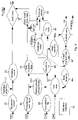
- FIG. 2 is an overview flow diagram of the method according to the invention.
- FIG. 3 is a schematic flow diagram of client-side steps of a first embodiment of the method according to the invention.
- FIG. 4 is a schematic flow diagram of server-side verification and authentication steps of a first embodiment of the method according to the invention
- FIG. 5 is a flow diagram of a further embodiment obtained by the modification of the embodiment illustrated in FIG. 3 ,
- FIG. 6 is a server-side flow diagram related to FIG. 5 , obtained by modifying the embodiment illustrated in FIG. 4 ,
- FIG. 7 is a schematic flow diagram of the encryption of an electronic file by the server.
- FIG. 8 is a schematic flow diagram of producing and signing a server evidence record.
- the main information technology devices and major components applied in the method according to the invention are shown in FIG. 1 .
- the method according to the invention is adapted for signing by a server 20 an electronic file made available or generated on a client device 10 .
- the client device 10 may be connected to the server 20 through a communications channel 30 .
- Such an electronic communications channel 30 may be established for example within an electronic communications network 32 , such as by way of example applying a wired and/or wireless local area network (LAN), a global IT network, particularly the Internet, as well as mobile telecommunications networks corresponding to the 3G or 4G standards, a GSM network, etc.
- LAN local area network
- GSM Global System for Mobile communications
- the client device 10 may be implemented as any such user communications device which comprises one or more processors 12 , data storage 14 , a client communications unit 16 , and peripherals 18 .
- the client device 10 may be a desktop, laptop or notebook computer, a cell phone (mobile phone)—particularly a smartphone, a tablet computer, etc.
- the data storage 14 is shown as an integrated part of the client device 10 , but the data storage 14 may also be external data storage means, i.e. the component herein referred to as data storage 14 is meant to comprise any internal and external data storage means accessible by the client device 10 .
- the data storage 14 may be implemented as any type of electronic, magnetic, optical or any other data storage means (such as memory, memory card, hard disk, external disk, etc.).
- the data storage 14 is preferably applied for storing PKI (Public Key Infrastructure) keys, at least the server's public encryption key 40 a corresponding to the server 20 .
- PKI Public Key Infrastructure
- the server's public encryption key 40 a is not stored in the data storage 14 but is made available temporarily for the client device 10 , being temporarily downloaded from the Internet for the purposes of the encryption process.
- the component referred to as the client communications unit 16 is meant to comprise any hardware and software components (i.e. network card, network connection, WiFi adapter, antenna, etc.) by means of which the client device 10 can establish the electronic communications channel 30 at least with the server 20 , over which channel electronic data can be exchanged.
- client communications unit 16 any hardware and software components (i.e. network card, network connection, WiFi adapter, antenna, etc.) by means of which the client device 10 can establish the electronic communications channel 30 at least with the server 20 , over which channel electronic data can be exchanged.
- the client device 10 comprises—either as a component thereof or as connected thereto as a peripheral 18 or as another external unit (i.e., connected in any manner to the client device 10 )—a biometric data acquisition unit 18 a and preferably at least one input interface 18 b and at least one output interface 18 c.
- the biometric data acquisition unit 18 a may, by way of example, be implemented as an iris scanner, whereby an iris image is received, and digital data representing the iris image are stored as biometric data.
- the biometric data acquisition unit 18 a may also be a fingerprint reader, applying which a fingerprint is received and digital data representing the fingerprint are stored as biometric data.
- the biometric data acquisition unit 18 a can be a device of any other type adapted for measuring/registering a biometric identifier (for example palm vein pattern, DNS) and for recording the resulting data.
- a biometric identifier for example palm vein pattern, DNS
- biometric data acquisition unit 18 a at the same time also functions as the input interface 18 b .
- the digitizer tablet may also be applied for inputting user commands for operating the software programs running on the client device 10 .
- the client device 10 preferably comprises at least one screen utilised as output interface 18 c .
- output interface 18 c may be contemplated, by way of example, printers or equipment adapted for writing different digital media (e.g. CD, DVD, floppy disc, memory sticks, memory cards, etc).
- the at least one input interface 18 b may be implemented, by way of example, as a keyboard, mouse, or other ordinary input device.
- the output interface 18 c may at the same time also be the input interface 18 b , for example a touchscreen.
- the data carrier media writer device may at the same time also function as the input interface 18 b provided that it is capable of reading and writing media.
- the keyboard can be implemented as a virtual keyboard, for example in case a touchscreen is applied as screen, a virtual keyboard can be displayed thereon, applicable as an input interface 18 b.
- the touchscreen may also perform the functions of the biometric data acquisition unit 18 a , i.e. in specific cases a single peripheral device can perform triple functions.
- the server 20 is meant to comprise other IT devices (such as desktop or laptop computers) capable of functioning as a server.
- the server 20 also comprises one or more processors 22 , data storage 24 and a server communications unit 26 .
- the data storage 24 may be implemented as any type of electronic, magnetic, optical or any other data storage means.
- the data storage 24 is shown as an integrated part of the server 20 , but the data storage 24 may also comprise external data storage means accessible by the server 20 , such as a hardware security module 24 ′ (HSM) shown in FIG. 1 .
- HSM hardware security module
- the data storage 24 is thus meant to comprise any internal and external data storage means (such as built-in ROM and RAM, external HSM, other external storage means, etc.) that are directly or indirectly accessible by the server 20 .
- the server 20 preferably possesses public key infrastructure (PKI) keys and other signing keys, such as the server's private encryption key 40 b and server's private signing key 41 corresponding to the server 20 , as well as the user's private signing keys 42 corresponding to the user, which can be stored in a key database 43 in the data storage 24 , and particularly preferably in the HSM 24 ′.
- PKI public key infrastructure
- the data storage 24 may preferably also store a user database 44 , and being included in or separate from it, a biometric database 45 adapted for storing biometric templates 45 a of the users.
- the user's private signing key 42 may, by way of example, also be a private encryption key based on the PKI infrastructure that can be applied by anyone for decrypting encrypted data using the public encryption key, but other signing algorithms not based on encryption are also known.
- algorithms of HMAC (hash-based message authentication code) type can also be used for the signing. These algorithms involve the generation of a combined hash value from the value of the key and the message itself. The hash has a double function: on the one hand it protects the identity of the message, and on the other it proves that it could only be generated by someone who had possessed the key.
- the main difference compared to the signing processes of the PKI (RSA) type is that this process essentially involves one type of key, i.e. the user's private signing key 42 , but there is no user's public signing key involved, and the signing algorithm consists in hash generation rather than encryption.
- the component referred to as the server communications unit 26 is meant to comprise any hardware and software components (i.e. network card, network connection, WiFi adapter, antenna, etc.) by means of which the server 20 can establish the electronic communications channel 30 at least with the client device 10 , over which channel electronic data can be exchanged.
- the server 20 can establish the electronic communications channel 30 at least with the client device 10 , over which channel electronic data can be exchanged.
- FIG. 2 an overview flow diagram of the method according to the invention is shown. The steps of the method, as well as the documents, data, algorithms and files utilised or generated in the course thereof are illustrated in more detail in FIGS. 2 to 8 .
- the method according to the invention is expediently preceded by the establishment of the communications channel 30 between the client device 10 and the server 20 .
- the communications channel 30 is preferably a secure channel that can be implemented applying by way of example the SSL, TLS, SNPv3, VPN, HTTPS, FTPS, TelnetS, NAPS, IPSec, etc. protocols, as it is well known to those skilled in the art.
- the communications channel 30 being a virtual data channel—may be disconnected and re-established, with optionally more than one virtual data channels being established between the client device 10 and the server 20 , but for the sake of simplicity these are collectively referred to as communications channel 30 .
- the provision of an electronic file 48 to be signed can also be regarded as the starting point of the method according to the invention.
- the electronic file 48 can be generated utilising the client device 10 , and thus it can for example be a document generated on the client device 10 or a picture file taken by the camera of the client device 10 applied as input interface 18 b .
- the electronic file 48 to be signed by the user of the client device 10 is not generated by the client device 10 itself but it is received by the client device 10 from an external source, such as via electronic mail, or the electronic file 48 is downloaded from the Internet or read from a data storage medium (e.g. CD, DVD, memory stick, etc.) applying a (writer)/reader device as input interface 18 b , or is received from the server 20 or from elsewhere.
- a data storage medium e.g. CD, DVD, memory stick, etc.
- Steps 1 - 8 of a first variant/embodiment of the method according to the invention presented in FIG. 2 are illustrated in detail in FIG. 3 .
- a challenge value 50 is generated utilising the server 20 .
- the challenge value 50 comprises one or more projection parameters 52 (typically numbers).
- the challenge value 50 may optionally also contain a time stamp that is either generated by the server 20 itself, or—upon request of the server 20 —by an external time stamp server, for instance according to the RFC3161 protocol.
- step 2 the challenge value 50 is transferred by the server 20 to the client device 10 through the communications channel 30 .
- step 3 the client device 10 is applied for extracting the one or more projection parameters 52 from the challenge value 50 .
- This step can of course be carried out any time before using the projection parameters 52 , or simultaneously therewith.
- the user's biometric data 54 are recorded on the client's 10 side utilising the biometric data acquisition unit 18 a , the biometric data possibly comprising one or more static or dynamic data items (data sets) recorded based on the physical characteristics of the user. For example, in case a digitizer tablet is applied as biometric data acquisition unit 18 a , a handwritten signature produced using a digital stylus or the user's finger as a writing device is received and recorded as biometric data 54 .
- the biometric data 54 may be for example the coordinates of the location of pressing the writing device against the tablet surface, the coordinates of the location of lifting the writing device from the tablet surface, the time function of writing device coordinates, the time function of writing device speed, the time function of writing device acceleration, the time function of writing device pressure force, or a combination of more than one such data.
- an image of the signature is displayed on the screen of the client device 10 , applied as the output device 18 c , thereby providing visual feedback to the user.
- This is especially efficient in case the biometric data acquisition unit 18 a at the same time also functions as a screen, as with PDA-s, tablet computers, touchscreen cell phones, etc.
- biometric data acquisition unit is implemented as an iris scanner, an iris image is received, and digital data representing the iris image are recorded as biometric data 54 .
- biometric data acquisition unit is a fingerprint reader, a fingerprint is recorded and digital data representing the fingerprint are stored as biometric data 54 .
- the client device 10 is applied for generating an evidence record 70 .
- the client device 10 is applied for generating a hash 49 of the electronic file 48 utilising a one-way secure hash algorithm 60 a , which by way of example be the SHA-256, SHA-512, etc. algorithm.
- the hash 49 generated utilising the hash algorithm 60 a represents such condensed data from which it is impossible to infer the original electronic file 48 .
- a characteristic feature of the hash algorithms 60 a is that the modification of any part of the original electronic file 48 causes an avalanche effect in the hash 49 , due to which the hash becomes completely different.
- a further important characteristic of the hash algorithm 60 a is that no data files can be produced from it for which the algorithm would generate the same hash 49 .
- the generation of the evidence record 70 also involves the generation of reduced biometric data 56 from the user's biometric data 54 with a projection algorithm applying one or more projection parameters 52 .
- projection is used to refer to one-way mathematical mappings, or other reductions, of data which result in such reduced data that cannot be used for restoring the original data, while at the same time the reduced data can only be generated by a person who is in possession of the original data and knows the projection parameters.
- projection algorithms applying projection (or, in other words, data reduction) parameters are well known for those skilled in the art, the algorithms incorporating, by way of example, the projection of the recorded data on a predetermined plane or axis or processing the data by means of a neural network.
- a static signature image (reduced biometric data 56 ) can be generated from the dynamic signature data recorded with a handwritten signature recorded as biometric data 54 .
- the reduced biometric data 56 is characteristic for the user but cannot be applied for restoring the original biometric data 54 .
- the reduced biometric data 56 serves as evidence for that its generator—in our case, the client device 10 —had been in possession of the original biometric data 54 and the projection parameters 52 sent with the challenge value 50 .
- the client device 10 is applied for generating the hash 58 of the reduced biometric data 56 utilising a one-way secure hash algorithm 60 b which may be identical to or different from the hash algorithm 60 a.
- the evidence record 70 is then generated by the client device 10 by associating the challenge value 50 , the hash 58 of the reduced biometric data 56 , and the hash 49 of the electronic file 48 .
- Data association can be performed applying any known suitable method, such as the bitwise XOR operation which combines the three data in such a manner that none of them can be inferred from the result, but verifiability is retained.
- a hash function adapted for generating a hash (the evidence record 70 ) by concatenating the three data can also be applied here.
- the evidence record 70 may in addition contain further data.
- the evidence record 70 proves that the electronic file 48 and the biometric data 54 originate from the given client device 10 .
- an external attacker tried to infuse previously recorded biometric data 54 into the system with a document to be signed, he could not produce the evidence record 70 corresponding to it since he does not possess the challenge value 50 (which may optionally also contain a time stamp to prevent tampering). Because the challenge value 50 contains unique parameters generated for each signing event, the biometric data 54 cannot be used twice, either by accident or purposefully.
- the evidence record 70 is preferably signed applying a digital signing algorithm 71 utilising the client device 10 .
- the signing algorithm 71 can be for example PKI-based (e.g. RSA), password-based, single-use password based or any other solution that can be adapted to suit the given situation.
- the signing process results in a signed evidence record 72 .
- step 7 the biometric data 54 and/or the electronic file 48 to be signed are preferably signed by the client device 10 , which may be performed applying PKI-based encryption using the server's public encryption key 40 a , such that the encrypted biometric data 64 and encrypted electronic file 68 thus produced can only be decrypted using the server's private encryption key 40 b stored in the key database 43 of the server 20 .
- step 8 the signed evidence record 72 , the preferably encrypted biometric data 64 and the preferably encrypted electronic file 68 are transferred by the client device 10 to the server 20 through the communications channel 30 .
- preferably one or more user data 74 items (such as user identifier, user PIN, etc.) are sent to the server 20 by the client device 10 before, during or after the completion of the above presented method.
- user data 74 can be associated with the above listed components.
- the user data 74 can, however, be sent to the server 20 (preferably encrypted) separately from the evidence record 70 , typically for user identification, which requires at least such identifier data on the basis of which the server 20 can, for example, find out which user's private signing key 42 is to be used of the keys stored in the key database 43 , or, for example, establish which user's user data 74 are to be used for generating the digital signature (described in detail below) of the data stored in the user database 44 , or, for example, establish which user's biometric template 45 a —the unique biometric sample (template) corresponding to the given user—is to be retrieved from the biometric database 45 .
- Other information made available to the server 20 by data communication may also perform the function of the user identifier—functioning as user data 74 —such as a phone number (if a smartphone is applied as client device 10 ), or a static IP address (in case a desktop computer is applied as client device 10 ), etc.
- Steps 9 - 11 of a first variant of the method according to the invention presented in FIG. 2 are illustrated in detail in FIG. 4 .
- the server 20 is applied for identifying the user of the client device 10 and for defining at least one user data 74 item.
- This latter can be user data 74 sent by the client device 10 , or further user data 74 items retrieved from the user database 44 based on the user data 74 sent by the client device.
- An event related to step 9 may be user authentication, during which, by way of example, the signature of the evidence record 72 signed by the client device 10 is verified, and the user is authenticated accordingly.
- authentication is performed based on the biometric data 54 .
- step 10 first the encrypted biometric data 64 sent by the client device 10 are decrypted with the server's private encryption key 40 b (or, optionally, using the symmetric key decrypted with the server's private encryption key 40 b ).
- the biometric template 45 a corresponding to the user specified by the user data 74 is retrieved from the biometric database 45 , the biometric template 45 a being then compared by the server 20 against the decrypted biometric data 54 using a suitable software program (by way of example, a software program comprising neural network-based, projection-based, CRC-based or other similar algorithms).
- the authenticity of the handwritten signature is verified by the program running on the server 20 using earlier specimen signatures of the given user as a biometric template 45 a .
- the process continues, otherwise the request for signing the electronic file 48 is rejected and the process is stopped.
- biometric data 54 The advantage of authentication performed using biometric data 54 is that the user does not have to remember any PIN codes. Authentication performed using a handwritten signature as biometric data 54 is particularly preferred because it is the closest thing to signing a paper document in the accustomed way.
- biometric data 54 sent to the server 20 are stored in the biometric database 45 as respective biometric templates 45 a corresponding to the given users, while the server 20 also checks whether the biometric data 54 currently submitted is identical to biometric templates 45 a stored earlier, or portions thereof, thereby providing protection against re-submitting earlier biometric data 54 .
- step 11 a verification evidence record 70 ′ is generated utilising the server 20 according to the following (see FIG. 4 ):
- the server 20 is utilised for generating reduced biometric verification data 56 ′ from the biometric data 54 applying a projection using the projection parameter 52 sent in the challenge value 50 , with the same projection algorithm that was used at the client side for generating the reduced biometric data 56 . Subsequently, the hash 58 ′ of the reduced biometric verification data 56 ′ is generated with the same hash algorithm 60 b that was applied at the client side for generating the hash 58 of the reduced biometric data 56 .
- the server 20 is utilised for generating the hash 49 ′ of the electronic file 48 with the same hash algorithm 60 a that was used for generating the hash 49 of the electronic file 48 at the client side.
- a verification evidence record 70 ′ is then generated by the server 20 , associating the challenge value 50 , the hash 58 ′ of the reduced biometric verification data 56 ′, and the hash 49 ′ of the electronic file 48 , and is compared against the evidence record 70 sent by the client device 10 .
- the digital signature process is continued, otherwise the request is rejected, and the process is halted.
- FIGS. 5 and FIG. 6 Corresponding steps of a second variant of the method according to the invention are illustrated in FIGS. 5 and FIG. 6 , which correspond to modified versions of FIG. 3 and FIG. 4 , respectively.
- a portion of the parameter includes a text, which is to be handwritten by the signatory, and in case the same text is never to be written twice it is ensured that no handwriting corresponding to a different parameter value (text) can later be generated using a fixed text recorded earlier.
- the implementation of the projection parameter and the biometric data reduction corresponding thereto can be classified in three major categories. Each of these categories involve a transformation performed depending on the parameter (these three categories can be applied also for the first variant of the invention, shown in FIG. 3 and FIG. 4 ).
- the network has 5 layers and the submitted parameter contains the data of the first two layers, then the inputs of the 3rd layer will be received from the client side as reduced biometrics, and the server will run the 3rd, 4th and 5th layers in the authentication module.
- biometric templates applied in case of the three above mentioned categories are as follows.
- the biometric database 45 and the biometric templates 45 a contained in it typically include the biometric samples themselves that were recorded earlier (e.g. signatures), since they can be applied for computing all the information required during the authentication process.
- the data reduction parameters such as the parametrisation of the projection line or the parameters of other selection decisions are different for each session, and the reduction mappings should be able to be calculated again also for the samples/signatures contained by the template.
- a special subcase of this could be when a finite number of pre-recorded “projections”, i.e.
- reduced biometrics are applied (for example, projections onto 3 predetermined lines), in which case the reference data series need not be re-computed by the authentication module using the full biometric data set (recorded at the time of registration), since the data can be computed in advance, during the registration process.
- the full biometric sample is not known even to the authentication module itself.
- the biometric template of a given person may consist of the pre-computed reduced data series, since these data can be generated at the time the person is registered.
- the biometric template of a person is constituted by the weight values and settings of the neural network trained specifically for the given person.
- the neural network has to exist at the time the parameter value is submitted (since the parameter is constituted by the first layers of the network), and—due to its nature—the network cannot be generated (trained) again in exactly the same way as before.
- the settings of the neural network should therefore be stored in the biometric template.
- biometric template may:
- FIG. 5 shows a flow diagram including the client-side steps of a second variant of the invention.
- this second variant of the invention differs from the embodiment described above in that, for enhanced safety, the full biometric data are not recorded at the client side, but instead the projection parameter 52 carried by the challenge value 50 already determines the manner in which biometric data are recorded, i.e. instead of the full biometrics only the reduced biometric data 56 are recorded at the client side.
- the reduced data can be recorded in different ways.
- the biometric data acquisition unit 18 a stores in its memory and passes on for further processing exclusively the reduced biometric data 56 .
- the full biometric data is temporarily present in the memory of the biometric data acquisition unit 18 a but only the partial content determined by the projection parameter 52 is recorded and submitted.
- the embodiment according to FIG. 5 differs from the embodiment illustrated in FIG. 3 in that in the course of the method only the reduced biometric data 56 are available for submission to the server 20 , preferably in encrypted form, i.e. as encrypted reduced biometric data 65 .
- the data content of the projection parameter 52 included in the challenge value 50 can vary very widely.
- the challenge value 50 is constituted by the projection parameter 52 itself, consisting of a single parameter only.
- the challenge value 50 contains further data in addition to the projection parameter 52 , which data do not take part in the data reduction process.
- the projection parameter 52 can be a single parameter or even a parameter set, as it is required for the input layer, the weights of the layers, and optionally other parameters of the network in case of data processing by a neural network.
- projection parameter 52 there is meant in the widest possible sense any parameter or parameter set described above.
- projection in this context does not imply that data reduction can only be performed by projection taken in the narrow sense, but by the projection parameter 52 there is meant any parameter by which data reduction of the biometric sample can be performed.
- projection parameter 52 any type of data reduction parameter or parameter set is understood in the widest possible sense.
- FIG. 6 the processes related to the server-side steps of the second variant of the invention, shown in FIG. 5 , are illustrated.
- the full biometric data set is not received at the server's side, only the—preferably encrypted—encrypted reduced biometric data 65 .
- the reduced biometric data 56 are decrypted using the server's private encryption key 40 b and can be later applied for generating the verification evidence record 70 ′ or preferably for authentication purposes.
- the reduced biometric data 56 are available at the server side, without there being a need for the projection parameter 52 to produce them.
- this embodiment of the invention is more secure than the embodiments according to FIGS. 3 and 4 because here the full biometric sample is not communicated, not even in encrypted form.
- the reduced biometric data 56 can be utilised for authentication at the server side.
- the biometric template 45 a corresponding to the given user is identified among the biometric templates 45 a stored in the biometric database 45 utilising the corresponding user data 74 , and then the reduced biometric template verification data 56 ′′ are produced from the given biometric template 45 a by means of the projection parameter 52 carried by the challenge value 50 .
- Authentication can therefore be carried out by comparing the reduced biometric data 56 (being received from the client side in encrypted form and then decrypted) and the reduced biometric template verification data 56 ′′.
- Steps 12 - 16 of the method according to the invention are illustrated in detail in FIG. 7 .
- the server 20 is applied for generating a server certificate 80 by associating at least the hash 49 of the electronic file 48 , the at least one user data 74 item, and at least the signature data 78 related to the time of the signature.
- the at least one user data 74 item can be user data 74 sent by the client device 10 , or other data retrieved from the user database 44 based on the user data 74 sent by the client device.
- User data 74 applied for generating the server certificate 80 comprise typically one or more of the following data items: the user's (signatory's) name, birth data, birthplace, mother's name, address, ID card number, etc.
- Signature data 78 are metadata that describe the “circumstances” of the signature event, comprising typically one or more of the following: date of signing, information on the client device 10 , information on the server 20 , the name of the signed electronic file 48 , etc.
- the server certificate 80 is preferably signed by the server 20 with the server's private signing key 41 , in order to produce a signed server certificate 82 that can later be utilised to definitively establish that the signature originated from the server 20 .
- the server's private signing key 41 may be identical to the server's private encryption key 40 b applied during the previous steps.
- the signed server certificate 82 can, however, be generated utilising a different key, or a different signing algorithm, the applicable signature algorithms for example include algorithms of the HMAC (hash-based message authentication code) type.
- step 14 the server 20 is utilised for generating visually displayable biometric data 54 a optionally from the biometric data 54 (or in case of the embodiment according to FIGS. 5 and 6 , from the reduced biometric data 56 ) with a one-way mapping algorithm 84 .
- a static signature image is produced from the recorded dynamic data of a handwritten signature.
- the visually displayable biometric data 54 a are produced from other types of biometric data 54 (such as fingerprints, palm vein images, iris images), but in case of these biometric data types visually displayable biometric data 54 a is not typically produced.
- the mapping algorithm 84 may optionally also be based on the projection algorithm implemented using the projection parameter 52 .
- step 15 the server 20 is utilised for generating a digital signature 85 by associating the signed server certificate 82 , the hash 49 of the electronic file 48 , and—in case they are available—the visually displayable biometric data 54 .
- data association is preferably performed by packaging the data in a data package.
- the digital signature 85 is associated with the electronic file 48 , by way of example by embedding it therein, or by including both in a common standard—for example, XML—file, thereby producing a digitally signed electronic file 86 .
- Embedding is preferably performed such that the visually displayable biometric data 54 a can be viewed as a signature image upon opening the digitally signed electronic file 86 .
- the digital signature 85 may of course also contain other data.
- the digitally signed electronic file 86 is also signed on behalf of the user utilising the server 20 , by way of example applying the user's private signing key 42 so as to obtain a doubly signed electronic file 88 .
- the user's public signing key anyone can make it sure that the doubly signed electronic file 88 was signed with the user's private signing key 42 corresponding to the given user (the signatory).
- Step 17 of the method according to the invention is illustrated in detail in FIG. 8 .
- step 17 the server 20 is utilised for generating a server evidence record 90 by associating at least the challenge value 50 , the biometric data 54 (or, in the embodiment according to FIGS. 5 and 6 , the reduced biometric data 56 ) and the hash 49 of the electronic file 48 (for example by the bitwise XOR operation mentioned above, or with a hash algorithm), the server evidence record 90 being then signed with the server's private signing key 41 , and the signed server evidence record 92 thus obtained being stored.
- the circumstances of the signing event, as well as the data utilised in the course thereof, can be known from the signed server evidence record 92 using the server's public signing key 40 a .
- the server evidence record 90 can be used later on (even years later) to prove that the given signing transaction with the given content did actually take place. This may be required for example for court proceedings. In such cases the full biometric data 54 might be required, and therefore preferably the full biometric data set is included in the server evidence record 90 rather than only the reduced biometric data 56 , the hash 58 thereof, or the visible biometric data 54 a.
- the above process may be carried out in case of multiple signatories, when of course the biometric data 54 of more than one users are recorded using the biometric data acquisition unit 18 a , carrying out the respective operations for each biometric data 54 set, while at the server side visible biometric data 54 a are produced from all of the biometric data 54 sets, and are all included in the digital signature 85 .
- the invention goes against the general engineering approach preferring simplification.
- Common engineering sense would suggest that a common digital signature should be applied to the biometric data and the original document, thereby “linking” both in an authentic manner.
- the biometrics and the document are known, it can be verified whether the given biometrics correspond to the given document.
- the invention makes this conventional solution more secure; in order to prevent the biometrics from getting disclosed it is stored and used in an encrypted/reduced form.
- the solution is adapted for producing challenge-based reduced biometrics that are included in an evidence record signed using both the document and the challenge parameters.
- the signed evidence record and the reduced biometrics can be handed over to any non-trusted entity because it cannot be applied for restoring the original biometrics due to the characteristics of the projection algorithm, while the reduced value will be unique for each signature since it can only be generated using different parameters every time (i.e. no two identical reduced images need to be applied even in case of identical biometrics). Since the authenticity of the signed evidence record can be verified by the non-trusted entity, the entity can make sure that the appropriate biometrics are linked with the given document.
- the authentication method according to the invention also comprises the above described steps, with any of the preferred embodiments presented above being applicable for the authentication method.
- any of the preferred embodiments presented above being applicable for the authentication method.
- a challenge value 50 comprising a projection parameter 52 is transferred from the server 20 to a client device 10 through a communications channel 30 ,
- the biometric data acquisition unit 18 a connected to the client device 10 is utilised for recording reduced biometric data 56 applying a projection utilising the projection parameter 52 ,
- the client device 10 is utilised for transferring the reduced biometric data 56 to the server 20 through the communications channel 30 ,
- the server 20 is utilised for identifying the user of the client device 10 .
- reduced biometric template verification data 56 ′′ are generated from the user's biometric template 45 a applying a projection comprising the projection parameter 52 , and the authentication is performed by comparing the reduced biometric data 56 against the reduced biometric template verification data 56 ′′.
- the user is identified based on the reduced biometric data 56 .
- the authentication method is based on a client-server biometric data acquisition architecture wherein the challenge value, sent by the server, is used by a biometric data acquisition unit connected to or incorporated in the client for recording reduced biometric data.
- the biometric data acquisition unit may be by way of example a tablet device or a cell phone (smartphone) and the software running on it, i.e. the biometric data acquisition unit is built in the client.
- the server may, for example, be a central service adapted for identifying the user based on the biometrics recorded by the device and for granting access to specific services depending on the result of the identification.
- the biometrics may for example be constituted by a handwritten signature on the touchscreen, an iris image taken by the device's camera, a fingerprint recorded by the device (provided the device has the necessary capability), or gesture recognition performed using the device's camera. In case of this embodiment reduction is performed expediently by the software running on the tablet.
- the biometric data acquisition device can be a “signature pad” (a digitizer tablet with a stylus which may also have its own display—essentially the same as a tablet device), which is connected to a PC by a USB connector.
- the “server” can even be the PC itself, running a software application adapted for utilising the recorded handwritten signature data.
- a remote server can of course be applied also in this case, when it is the PC that sends the data to the server via a communications link.
- the data reduction procedure is performed already inside the “signature pad” device, since in this case the full biometrics do not get out of the physically enclosed and protected device.
- the biometric data acquisition unit may also be a simple computer mouse connected to a PC.
- a software application may be applied for recording the user's mouse movements during web browsing. Mouse/hand movements can be regarded as biometric data characteristic for a given individual. Based on the recorded data, psychological characteristics of the user can also be obtained, which can be applied even for displaying customised advertisements targeted at the user.
- a PC-connected camera can be applied for recording the user's eye movements (as biometric data). In these examples data reduction is expediently performed by the software application running on the PC.
- the challenge value would comprise
- Another parameter adapted for reducing dynamic biometric data to static ones i.e. practically the time and pressure force parameters are deleted from the original data set, an image is drawn from the remaining series of points and is preferably converted to a predetermined size).
- the reduced biometrics is the aggregation of the two types of reduced information, with the two portions being used by the server in two different ways.
- the authentication method based on reduced biometrics has the advantage that it allows personal identification to be performed by such entities/services that are not allowed to possess full biometric data due to statutory prohibition or are not at the security level that would allow them to protect the identity of a person; or are not sufficiently trusted, as service providers, by the persons to be identified.
- the authentication method according to the invention is also applicable for building an anonymous identification system, because biometric data applicable for identity theft are not stored in the client and are not transferred inside the system.
- multiple cameras can be installed inside the stores and hallways of a shopping mall.
- the camera system may gather reduced face/body shape/movement information on individual persons, transferring only this reduced information to the server. Based on the reduced information the server tries to recognise the person. In case the person is not recognised, he or she is identified as a new customer, the corresponding biometric sample (reduced data) is stored together with an associated identification number.
- the system monitors the movement of the person in the mall (which shops he or she enters, before which store windows he or she stops, how much time he or she spends at certain locations, in which restaurant he or she has dinner, which product he or she buys—this latter can be established using the cash desk camera and cash register information), i.e. the system can identify customer habits and preferences. Based on the customer preferences of previously recognised and identified persons the system is capable of displaying personalised advertisements anywhere (e.g. on a dynamic TV wall).
- the recognition/identification system allows individual stores to present personalised sales offers to customers upon entering the store.
Abstract
Description
- 1. Reduced biometrics, where a transformation is determined directly by the given parameter. Examples:
- 2. Reduced biometrics, where the parameter is for selecting the authentication algorithm (or more than one algorithm at the same time). In this case the verification result of the biometric data is composed of the individual verification results of multiple characteristic features. For example, the temporal change of the X- and Y-direction velocities and the angles of the tangent vectors are checked; and the final decision is taken based on the scores yielded by the individual comparisons. In this case the reduction parameter determines only the type of reduction that is to be performed by the recording device. If, for example, the parameter indicates that the authentication is to be performed using the X-direction acceleration and the change of angle of the tangent vector, then these two data series (=reduced biometrics) will be recorded, from which it is impossible to restore the original biometrics. Examples:
- 3. Reduced biometrics, where a transformation is determined indirectly by the given parameter. By way of example, solutions implemented using neural networks fall in this category. For example, the neural network applied for authentication may consist of 3 layers. The given neural network has a fixed structure, and the same network—defined by its structure and weights—is always applied for authenticating a given person. A unique neural network is trained for each person to be authenticated, which network can only be applied for recognising the given person. The parameter value expediently contains the weights and optionally other settings of the first layer of the neural network. During the registering process, all the second layer's input parameters are calculated based on the
projection parameter 52 sent by the server, which effectively constitutes the reduced biometrics from which it is impossible to restore the signature. The authentication module does not have to compute the neural network again based on the parameter value (the network is already known to the module because it was built during the signature registering process), and thus all the server has to do is make sure that the first layer defined by the parameter is identical to the first layer of the neural network that is already known, and if so, the 2nd and 3rd layers will be run in the authentication module.
Claims (11)
Applications Claiming Priority (5)
| Application Number | Priority Date | Filing Date | Title |
|---|---|---|---|
| HUP1400392 | 2014-08-18 | ||
| HUP1400392 | 2014-08-18 | ||
| HUP1500259 | 2015-05-29 | ||
| HU1500259A HUP1500259A3 (en) | 2015-05-29 | 2015-05-29 | Method for digitally signing electronic files and method for authentication |
| PCT/HU2015/000055 WO2016027111A1 (en) | 2014-08-18 | 2015-06-15 | Methods for digitally signing an electronic file, and authenticating method |
Related Parent Applications (2)
| Application Number | Title | Priority Date | Filing Date |
|---|---|---|---|
| US15/502,616 Continuation US10547453B2 (en) | 2014-08-18 | 2015-06-15 | Methods for digitally signing an electronic file and authentication method |
| PCT/HU2015/000055 Continuation WO2016027111A1 (en) | 2014-08-18 | 2015-06-15 | Methods for digitally signing an electronic file, and authenticating method |
Publications (2)
| Publication Number | Publication Date |
|---|---|
| US20200153638A1 US20200153638A1 (en) | 2020-05-14 |
| US11310058B2 true US11310058B2 (en) | 2022-04-19 |
Family
ID=89991841
Family Applications (2)
| Application Number | Title | Priority Date | Filing Date |
|---|---|---|---|
| US15/502,616 Active 2036-04-29 US10547453B2 (en) | 2014-08-18 | 2015-06-15 | Methods for digitally signing an electronic file and authentication method |
| US16/734,500 Active US11310058B2 (en) | 2014-08-18 | 2020-01-06 | Methods for digitally signing an electronic file and authentication method |
Family Applications Before (1)
| Application Number | Title | Priority Date | Filing Date |
|---|---|---|---|
| US15/502,616 Active 2036-04-29 US10547453B2 (en) | 2014-08-18 | 2015-06-15 | Methods for digitally signing an electronic file and authentication method |
Country Status (8)
| Country | Link |
|---|---|
| US (2) | US10547453B2 (en) |
| EP (2) | EP3183680B1 (en) |
| CN (1) | CN107209821B (en) |
| EA (1) | EA037018B1 (en) |
| HU (2) | HUE058164T2 (en) |
| MY (1) | MY179592A (en) |
| SG (1) | SG11201700760TA (en) |
| WO (1) | WO2016027111A1 (en) |
Families Citing this family (33)
| Publication number | Priority date | Publication date | Assignee | Title |
|---|---|---|---|---|
| US20150006261A1 (en) | 2013-06-28 | 2015-01-01 | Healthtap, Inc. | Systems and method for evaluating and selecting a healthcare professional |
| EP3326096B1 (en) * | 2015-07-20 | 2022-02-16 | Notarize, Inc. | System and method for validating authorship of an electronic signature session |
| WO2017117357A1 (en) * | 2015-12-30 | 2017-07-06 | Xiaolin Zhang | System and method for data security |
| US10291604B2 (en) * | 2016-06-03 | 2019-05-14 | Docusign, Inc. | Universal access to document transaction platform |
| US10498541B2 (en) * | 2017-02-06 | 2019-12-03 | ShocCard, Inc. | Electronic identification verification methods and systems |
| US10484373B2 (en) | 2017-04-11 | 2019-11-19 | Mastercard International Incorporated | Systems and methods for biometric authentication of certificate signing request processing |
| US10706349B2 (en) | 2017-05-25 | 2020-07-07 | Texas Instruments Incorporated | Secure convolutional neural networks (CNN) accelerator |
| CN107171787B (en) * | 2017-06-08 | 2020-04-14 | 杭州云证网络科技有限公司 | Data blind signing and storing method and system based on multiple Hash algorithm |
| GB2565282B (en) * | 2017-08-02 | 2021-12-22 | Vnc Automotive Ltd | Remote control of a computing device |
| US10630483B2 (en) * | 2017-10-23 | 2020-04-21 | Legitipix, LLC | Anonymous image/video digital signature insertion and authentication |
| US11281887B2 (en) | 2017-11-29 | 2022-03-22 | Vynca, Inc. | Multiple electronic signature method |
| EP3721578B1 (en) | 2017-12-08 | 2022-09-07 | Ping Identity Corporation | Methods and systems for recovering data using dynamic passwords |
| UA127687C2 (en) * | 2018-02-07 | 2023-11-29 | Кріпто Лінкс Лтд | Signing method system and/or device |
| US11423164B2 (en) * | 2018-05-21 | 2022-08-23 | Vynca, Inc. | Multiple electronic signature method |
| WO2020035009A1 (en) * | 2018-08-15 | 2020-02-20 | 飞天诚信科技股份有限公司 | Authentication system and working method therefor |
| CN109376554B (en) * | 2018-10-16 | 2022-02-11 | 周金明 | Multi-terminal electronic document examination and signature method and system based on labels and views |
| US11082221B2 (en) | 2018-10-17 | 2021-08-03 | Ping Identity Corporation | Methods and systems for creating and recovering accounts using dynamic passwords |
| KR20200100481A (en) * | 2019-02-18 | 2020-08-26 | 삼성전자주식회사 | Electronic device for authenticating biometric information and operating method thereof |
| TWI704794B (en) * | 2019-03-29 | 2020-09-11 | 區塊科技股份有限公司 | System and implement method for signing and verifying contract in a block chain network |
| US11303452B2 (en) | 2019-04-03 | 2022-04-12 | Keychainx Ag | Biometric digital signature generation for identity verification |
| US11595210B2 (en) | 2019-05-06 | 2023-02-28 | Inferati Inc. | Accurate, real-time and secure privacy-preserving verification of biometrics or other sensitive information |
| CN110445771B (en) * | 2019-07-19 | 2022-07-08 | 平安科技(深圳)有限公司 | Block chain-based interactive record evidence obtaining method, device, medium and server |
| CN110427742B (en) * | 2019-08-06 | 2021-05-25 | 北京如优教育科技有限公司 | Authentication service platform content saving system, method and storage medium |
| CN110795766B (en) * | 2019-11-04 | 2022-04-08 | 苏州苏大苏航档案数据保全有限公司 | Electronic file data security system and method |
| MX2022009621A (en) * | 2020-02-07 | 2022-11-07 | Veridas Digital Authentication Solutions S L | Electronic signatures. |
| CN111414608B (en) * | 2020-03-10 | 2023-04-18 | 飞天诚信科技股份有限公司 | Method for receiving registration by server |
| FR3111721B1 (en) * | 2020-06-17 | 2023-08-11 | Idemia Identity & Security France | Method for authenticating a user on a client device |
| CN112994896A (en) * | 2021-03-17 | 2021-06-18 | 黑龙江恒讯科技有限公司 | Vein identification based digital certificate authentication method |
| CN113313092B (en) * | 2021-07-29 | 2021-10-29 | 太平金融科技服务(上海)有限公司深圳分公司 | Handwritten signature recognition method, and claims settlement automation processing method, device and equipment |
| CN114172890B (en) * | 2021-11-03 | 2024-02-27 | 阿里巴巴(中国)有限公司 | File second transmission processing method and device, storage medium and electronic equipment |
| TWI809552B (en) * | 2021-11-04 | 2023-07-21 | 核心智識股份有限公司 | Biometrics willingness signature generating device, system and the method for electronics document |
| US11552808B1 (en) | 2021-11-23 | 2023-01-10 | Uab 360 It | Method and apparatus for generating a dynamic security certificate |
| CN114553431A (en) * | 2022-01-27 | 2022-05-27 | 北京信息科技大学 | Communication method and device with memory function |
Citations (15)
| Publication number | Priority date | Publication date | Assignee | Title |
|---|---|---|---|---|
| WO1999033221A1 (en) | 1997-12-19 | 1999-07-01 | Koninklijke Philips Electronics N.V. | Secure proxy signing device and method for use |
| WO2001008352A1 (en) | 1999-07-21 | 2001-02-01 | Iridian Technologies, Inc. | Method and apparatus for implementing a biometric-based digital signature of document |
| CN1419664A (en) | 2000-02-23 | 2003-05-21 | 基姆·利珀 | A system and method for authenticating electronic documents |
| US6735695B1 (en) | 1999-12-20 | 2004-05-11 | International Business Machines Corporation | Methods and apparatus for restricting access of a user using random partial biometrics |
| US6959382B1 (en) * | 1999-08-16 | 2005-10-25 | Accela, Inc. | Digital signature service |
| WO2007034255A1 (en) | 2005-09-21 | 2007-03-29 | CSÍK, Balázs | Method, apparatus and system for generating a digital signature linked to a biometric identifier |
| US20080209227A1 (en) | 2007-02-28 | 2008-08-28 | Microsoft Corporation | User Authentication Via Biometric Hashing |
| US20100066493A1 (en) | 2008-09-15 | 2010-03-18 | Yaron Rachlin | Biometric processing using random projection transforms |
| WO2011005869A2 (en) * | 2009-07-07 | 2011-01-13 | Entrust & Title Ltd., A Bvi Corporation | Method and system for generating and using biometrically secured embedded tokens in documents |
| US20110126024A1 (en) | 2004-06-14 | 2011-05-26 | Rodney Beatson | Method and system for combining a PIN and a biometric sample to provide template encryption and a trusted stand-alone computing device |
| US20130138964A1 (en) | 2011-11-30 | 2013-05-30 | Advanced Biometric Controls, Llc | Verification of authenticity and responsiveness of biometric evidence and/or other evidence |
| US8612769B2 (en) | 2010-03-16 | 2013-12-17 | Stepover Gmbh | Electronic signature method and device |
| CN103888442A (en) | 2014-01-13 | 2014-06-25 | 黄晓芳 | System with integration of visualization biological characteristics and one-time digital signature and method thereof |
| US9166957B2 (en) | 2012-04-19 | 2015-10-20 | Martin Tomlinson | Digital file authentication using biometrics |
| US9596088B1 (en) | 2007-05-08 | 2017-03-14 | United Services Automobile Association (Usaa) | Systems and methods for biometric e-signature |
-
2015
- 2015-06-15 EA EA201790385A patent/EA037018B1/en unknown
- 2015-06-15 WO PCT/HU2015/000055 patent/WO2016027111A1/en active Application Filing
- 2015-06-15 EP EP15757322.1A patent/EP3183680B1/en active Active
- 2015-06-15 SG SG11201700760TA patent/SG11201700760TA/en unknown
- 2015-06-15 EP EP18162665.6A patent/EP3355224B1/en active Active
- 2015-06-15 HU HUE18162665A patent/HUE058164T2/en unknown
- 2015-06-15 MY MYPI2017700343A patent/MY179592A/en unknown
- 2015-06-15 US US15/502,616 patent/US10547453B2/en active Active
- 2015-06-15 HU HUE15757322A patent/HUE038266T2/en unknown
- 2015-06-15 CN CN201580056462.8A patent/CN107209821B/en active Active
-
2020
- 2020-01-06 US US16/734,500 patent/US11310058B2/en active Active
Patent Citations (17)
| Publication number | Priority date | Publication date | Assignee | Title |
|---|---|---|---|---|
| WO1999033221A1 (en) | 1997-12-19 | 1999-07-01 | Koninklijke Philips Electronics N.V. | Secure proxy signing device and method for use |
| WO2001008352A1 (en) | 1999-07-21 | 2001-02-01 | Iridian Technologies, Inc. | Method and apparatus for implementing a biometric-based digital signature of document |
| US6553494B1 (en) | 1999-07-21 | 2003-04-22 | Sensar, Inc. | Method and apparatus for applying and verifying a biometric-based digital signature to an electronic document |
| US6959382B1 (en) * | 1999-08-16 | 2005-10-25 | Accela, Inc. | Digital signature service |
| US6735695B1 (en) | 1999-12-20 | 2004-05-11 | International Business Machines Corporation | Methods and apparatus for restricting access of a user using random partial biometrics |
| CN1419664A (en) | 2000-02-23 | 2003-05-21 | 基姆·利珀 | A system and method for authenticating electronic documents |
| US7346779B2 (en) | 2000-02-23 | 2008-03-18 | Birmingham Systems Limited | System and method for authenticating electronic documents |
| US20110126024A1 (en) | 2004-06-14 | 2011-05-26 | Rodney Beatson | Method and system for combining a PIN and a biometric sample to provide template encryption and a trusted stand-alone computing device |
| WO2007034255A1 (en) | 2005-09-21 | 2007-03-29 | CSÍK, Balázs | Method, apparatus and system for generating a digital signature linked to a biometric identifier |
| US20080209227A1 (en) | 2007-02-28 | 2008-08-28 | Microsoft Corporation | User Authentication Via Biometric Hashing |
| US9596088B1 (en) | 2007-05-08 | 2017-03-14 | United Services Automobile Association (Usaa) | Systems and methods for biometric e-signature |
| US20100066493A1 (en) | 2008-09-15 | 2010-03-18 | Yaron Rachlin | Biometric processing using random projection transforms |
| WO2011005869A2 (en) * | 2009-07-07 | 2011-01-13 | Entrust & Title Ltd., A Bvi Corporation | Method and system for generating and using biometrically secured embedded tokens in documents |
| US8612769B2 (en) | 2010-03-16 | 2013-12-17 | Stepover Gmbh | Electronic signature method and device |
| US20130138964A1 (en) | 2011-11-30 | 2013-05-30 | Advanced Biometric Controls, Llc | Verification of authenticity and responsiveness of biometric evidence and/or other evidence |
| US9166957B2 (en) | 2012-04-19 | 2015-10-20 | Martin Tomlinson | Digital file authentication using biometrics |
| CN103888442A (en) | 2014-01-13 | 2014-06-25 | 黄晓芳 | System with integration of visualization biological characteristics and one-time digital signature and method thereof |
Non-Patent Citations (7)
| Title |
|---|
| Chinese Patent Office; Search Report in related Chinese Patent Application No. 2015800564628 dated Mar. 18, 2018; 2 pages. |
| European Patent Office; International Preliminary Report on Patentability in related International Patent Application PCT/HU2015/000055 dated Nov. 17, 2016; 6 pages. |
| European Patent Office; Search Report in related International Patent Application No. PCT/HU2015/000055 dated Oct. 15, 2015; 2 pages. |
| Hungarian Patent Office; Search Report in related Hungary Patent Application No. P1500259 dated Jun. 15, 2016; 2 pages. |
| JIN A.T.B.: "Cancellable Biometrics and Multispace Random Projections", COMPUTER VISION AND PATTERN RECOGNITION WORKSHOP, 2006 CONFERENCE ON NEW YORK, NY, USA 17-22 JUNE 2006, PISCATAWAY, NJ, USA,IEEE, PISCATAWAY, NJ, USA, 17 June 2006 (2006-06-17) - 22 June 2006 (2006-06-22), Piscataway, NJ, USA , pages 164 - 164, XP010922679, ISBN: 978-0-7695-2646-1, DOI: 10.1109/CVPRW.2006.49 |
| Jin; Abstract from "Cancellable Biometrics and Multispace Random Projections," Computer Vision and Pattern Recognition Workshop, 2006 Conference on New York, NY, USA Jun. 17-22, 2006, NJ, USA, Jun. 17, 2006 , pp. 164, XP010922679, DOI: 10.1109/CVPRW.2006.49. |
| Orvos; Use Biometric Authentication to Produce Authentic Digital Signatures; https://nws.niif.hu/ncd2001/docs/eloadas/80; 8 pages. |
Also Published As
| Publication number | Publication date |
|---|---|
| MY179592A (en) | 2020-11-11 |
| EA201790385A1 (en) | 2017-09-29 |
| EP3355224B1 (en) | 2022-01-26 |
| CN107209821B (en) | 2018-08-14 |
| CN107209821A (en) | 2017-09-26 |
| HUE038266T2 (en) | 2018-10-29 |
| WO2016027111A1 (en) | 2016-02-25 |
| HUE058164T2 (en) | 2022-07-28 |
| EP3183680A1 (en) | 2017-06-28 |
| EP3355224A1 (en) | 2018-08-01 |
| US20200153638A1 (en) | 2020-05-14 |
| US10547453B2 (en) | 2020-01-28 |
| US20180212782A1 (en) | 2018-07-26 |
| EP3183680B1 (en) | 2018-03-21 |
| SG11201700760TA (en) | 2017-03-30 |
| EA037018B1 (en) | 2021-01-27 |
Similar Documents
| Publication | Publication Date | Title |
|---|---|---|
| US11310058B2 (en) | Methods for digitally signing an electronic file and authentication method | |
| US20210056195A1 (en) | Method and System for Securing User Access, Data at Rest, and Sensitive Transactions Using Biometrics for Mobile Devices with Protected Local Templates | |
| US10498541B2 (en) | Electronic identification verification methods and systems | |
| US10440019B2 (en) | Method, computer program, and system for identifying multiple users based on their behavior | |
| US9531710B2 (en) | Behavioral authentication system using a biometric fingerprint sensor and user behavior for authentication | |
| US20190311148A1 (en) | System and method for secure storage of electronic material | |
| US7024562B1 (en) | Method for carrying out secure digital signature and a system therefor | |
| US20160219046A1 (en) | System and method for multi-modal biometric identity verification | |
| US9189612B2 (en) | Biometric verification with improved privacy and network performance in client-server networks | |
| EP3721578A1 (en) | Methods and systems for recovering data using dynamic passwords | |
| WO2019199288A1 (en) | System and method for secure storage of electronic material | |
| WO2018145127A1 (en) | Electronic identification verification methods and systems with storage of certification records to a side chain | |
| JPWO2007094165A1 (en) | Identification system and program, and identification method | |
| JP2006209697A (en) | Individual authentication system, and authentication device and individual authentication method used for the individual authentication system | |
| US9280650B2 (en) | Authenticate a fingerprint image | |
| US20130088327A1 (en) | Template delivery type cancelable biometric authentication system and method therefor | |
| CA3057398C (en) | Securely performing cryptographic operations | |
| WO1999012144A1 (en) | Digital signature generating server and digital signature generating method | |
| WO2021249527A1 (en) | Method and apparatus for implementing motopay, and electronic device | |
| JP7250960B2 (en) | User authentication and signature device using user biometrics, and method thereof | |
| US20200204377A1 (en) | Digital notarization station that uses a biometric identification service | |
| KR20070044720A (en) | System and method for the one-time password's authentication by the human-face image | |
| US11681787B1 (en) | Ownership validation for cryptographic asset contracts using irreversibly transformed identity tokens | |
| CN111466097B (en) | Server-assisted privacy preserving biometric comparison | |
| RU2776258C2 (en) | Biometric comparison for privacy protection using server |
Legal Events
| Date | Code | Title | Description |
|---|---|---|---|
| FEPP | Fee payment procedure |
Free format text: ENTITY STATUS SET TO UNDISCOUNTED (ORIGINAL EVENT CODE: BIG.); ENTITY STATUS OF PATENT OWNER: SMALL ENTITY |
|
| FEPP | Fee payment procedure |
Free format text: ENTITY STATUS SET TO SMALL (ORIGINAL EVENT CODE: SMAL); ENTITY STATUS OF PATENT OWNER: SMALL ENTITY |
|
| STPP | Information on status: patent application and granting procedure in general |
Free format text: NON FINAL ACTION MAILED |
|
| STPP | Information on status: patent application and granting procedure in general |
Free format text: RESPONSE TO NON-FINAL OFFICE ACTION ENTERED AND FORWARDED TO EXAMINER |
|
| STPP | Information on status: patent application and granting procedure in general |
Free format text: FINAL REJECTION MAILED |
|
| STPP | Information on status: patent application and granting procedure in general |
Free format text: DOCKETED NEW CASE - READY FOR EXAMINATION |
|
| STPP | Information on status: patent application and granting procedure in general |
Free format text: NON FINAL ACTION MAILED |
|
| STPP | Information on status: patent application and granting procedure in general |
Free format text: RESPONSE TO NON-FINAL OFFICE ACTION ENTERED AND FORWARDED TO EXAMINER |
|
| STPP | Information on status: patent application and granting procedure in general |
Free format text: NOTICE OF ALLOWANCE MAILED -- APPLICATION RECEIVED IN OFFICE OF PUBLICATIONS |
|
| AS | Assignment |
Owner name: ROGAN, ANTAL, HUNGARY Free format text: ASSIGNMENT OF ASSIGNORS INTEREST;ASSIGNOR:LENGYEL, CSABA;REEL/FRAME:059268/0643 Effective date: 20181114 |
|
| STPP | Information on status: patent application and granting procedure in general |
Free format text: PUBLICATIONS -- ISSUE FEE PAYMENT VERIFIED |
|
| STCF | Information on status: patent grant |
Free format text: PATENTED CASE |