US11307485B2 - Switchable imager lens cover - Google Patents
Switchable imager lens cover Download PDFInfo
- Publication number
- US11307485B2 US11307485B2 US16/407,818 US201916407818A US11307485B2 US 11307485 B2 US11307485 B2 US 11307485B2 US 201916407818 A US201916407818 A US 201916407818A US 11307485 B2 US11307485 B2 US 11307485B2
- Authority
- US
- United States
- Prior art keywords
- imager
- cover
- electro
- lens
- vehicle
- Prior art date
- Legal status (The legal status is an assumption and is not a legal conclusion. Google has not performed a legal analysis and makes no representation as to the accuracy of the status listed.)
- Active, expires
Links
Images


Classifications
-
- B—PERFORMING OPERATIONS; TRANSPORTING
- B60—VEHICLES IN GENERAL
- B60R—VEHICLES, VEHICLE FITTINGS, OR VEHICLE PARTS, NOT OTHERWISE PROVIDED FOR
- B60R11/00—Arrangements for holding or mounting articles, not otherwise provided for
- B60R11/04—Mounting of cameras operative during drive; Arrangement of controls thereof relative to the vehicle
-
- G—PHYSICS
- G02—OPTICS
- G02F—OPTICAL DEVICES OR ARRANGEMENTS FOR THE CONTROL OF LIGHT BY MODIFICATION OF THE OPTICAL PROPERTIES OF THE MEDIA OF THE ELEMENTS INVOLVED THEREIN; NON-LINEAR OPTICS; FREQUENCY-CHANGING OF LIGHT; OPTICAL LOGIC ELEMENTS; OPTICAL ANALOGUE/DIGITAL CONVERTERS
- G02F1/00—Devices or arrangements for the control of the intensity, colour, phase, polarisation or direction of light arriving from an independent light source, e.g. switching, gating or modulating; Non-linear optics
- G02F1/01—Devices or arrangements for the control of the intensity, colour, phase, polarisation or direction of light arriving from an independent light source, e.g. switching, gating or modulating; Non-linear optics for the control of the intensity, phase, polarisation or colour
- G02F1/13—Devices or arrangements for the control of the intensity, colour, phase, polarisation or direction of light arriving from an independent light source, e.g. switching, gating or modulating; Non-linear optics for the control of the intensity, phase, polarisation or colour based on liquid crystals, e.g. single liquid crystal display cells
- G02F1/133—Constructional arrangements; Operation of liquid crystal cells; Circuit arrangements
- G02F1/1333—Constructional arrangements; Manufacturing methods
- G02F1/1335—Structural association of cells with optical devices, e.g. polarisers or reflectors
- G02F1/133526—Lenses, e.g. microlenses or Fresnel lenses
-
- G—PHYSICS
- G02—OPTICS
- G02F—OPTICAL DEVICES OR ARRANGEMENTS FOR THE CONTROL OF LIGHT BY MODIFICATION OF THE OPTICAL PROPERTIES OF THE MEDIA OF THE ELEMENTS INVOLVED THEREIN; NON-LINEAR OPTICS; FREQUENCY-CHANGING OF LIGHT; OPTICAL LOGIC ELEMENTS; OPTICAL ANALOGUE/DIGITAL CONVERTERS
- G02F1/00—Devices or arrangements for the control of the intensity, colour, phase, polarisation or direction of light arriving from an independent light source, e.g. switching, gating or modulating; Non-linear optics
- G02F1/01—Devices or arrangements for the control of the intensity, colour, phase, polarisation or direction of light arriving from an independent light source, e.g. switching, gating or modulating; Non-linear optics for the control of the intensity, phase, polarisation or colour
- G02F1/13—Devices or arrangements for the control of the intensity, colour, phase, polarisation or direction of light arriving from an independent light source, e.g. switching, gating or modulating; Non-linear optics for the control of the intensity, phase, polarisation or colour based on liquid crystals, e.g. single liquid crystal display cells
- G02F1/133—Constructional arrangements; Operation of liquid crystal cells; Circuit arrangements
- G02F1/1333—Constructional arrangements; Manufacturing methods
- G02F1/1335—Structural association of cells with optical devices, e.g. polarisers or reflectors
- G02F1/133528—Polarisers
-
- G—PHYSICS
- G03—PHOTOGRAPHY; CINEMATOGRAPHY; ANALOGOUS TECHNIQUES USING WAVES OTHER THAN OPTICAL WAVES; ELECTROGRAPHY; HOLOGRAPHY
- G03B—APPARATUS OR ARRANGEMENTS FOR TAKING PHOTOGRAPHS OR FOR PROJECTING OR VIEWING THEM; APPARATUS OR ARRANGEMENTS EMPLOYING ANALOGOUS TECHNIQUES USING WAVES OTHER THAN OPTICAL WAVES; ACCESSORIES THEREFOR
- G03B11/00—Filters or other obturators specially adapted for photographic purposes
- G03B11/04—Hoods or caps for eliminating unwanted light from lenses, viewfinders or focusing aids
- G03B11/043—Protective lens closures or lens caps built into cameras
-
- H—ELECTRICITY
- H04—ELECTRIC COMMUNICATION TECHNIQUE
- H04N—PICTORIAL COMMUNICATION, e.g. TELEVISION
- H04N23/00—Cameras or camera modules comprising electronic image sensors; Control thereof
- H04N23/50—Constructional details
- H04N23/55—Optical parts specially adapted for electronic image sensors; Mounting thereof
-
- H—ELECTRICITY
- H04—ELECTRIC COMMUNICATION TECHNIQUE
- H04N—PICTORIAL COMMUNICATION, e.g. TELEVISION
- H04N23/00—Cameras or camera modules comprising electronic image sensors; Control thereof
- H04N23/60—Control of cameras or camera modules
-
- H—ELECTRICITY
- H04—ELECTRIC COMMUNICATION TECHNIQUE
- H04N—PICTORIAL COMMUNICATION, e.g. TELEVISION
- H04N23/00—Cameras or camera modules comprising electronic image sensors; Control thereof
- H04N23/95—Computational photography systems, e.g. light-field imaging systems
- H04N23/957—Light-field or plenoptic cameras or camera modules
-
- H04N5/22541—
-
- H04N5/232—
-
- B—PERFORMING OPERATIONS; TRANSPORTING
- B60—VEHICLES IN GENERAL
- B60R—VEHICLES, VEHICLE FITTINGS, OR VEHICLE PARTS, NOT OTHERWISE PROVIDED FOR
- B60R11/00—Arrangements for holding or mounting articles, not otherwise provided for
- B60R2011/0001—Arrangements for holding or mounting articles, not otherwise provided for characterised by position
- B60R2011/004—Arrangements for holding or mounting articles, not otherwise provided for characterised by position outside the vehicle
-
- B—PERFORMING OPERATIONS; TRANSPORTING
- B60—VEHICLES IN GENERAL
- B60R—VEHICLES, VEHICLE FITTINGS, OR VEHICLE PARTS, NOT OTHERWISE PROVIDED FOR
- B60R2300/00—Details of viewing arrangements using cameras and displays, specially adapted for use in a vehicle
- B60R2300/10—Details of viewing arrangements using cameras and displays, specially adapted for use in a vehicle characterised by the type of camera system used
-
- G—PHYSICS
- G02—OPTICS
- G02B—OPTICAL ELEMENTS, SYSTEMS OR APPARATUS
- G02B27/00—Optical systems or apparatus not provided for by any of the groups G02B1/00 - G02B26/00, G02B30/00
- G02B27/0006—Optical systems or apparatus not provided for by any of the groups G02B1/00 - G02B26/00, G02B30/00 with means to keep optical surfaces clean, e.g. by preventing or removing dirt, stains, contamination, condensation
-
- G—PHYSICS
- G02—OPTICS
- G02B—OPTICAL ELEMENTS, SYSTEMS OR APPARATUS
- G02B5/00—Optical elements other than lenses
- G02B5/20—Filters
- G02B5/22—Absorbing filters
- G02B5/23—Photochromic filters
-
- G—PHYSICS
- G03—PHOTOGRAPHY; CINEMATOGRAPHY; ANALOGOUS TECHNIQUES USING WAVES OTHER THAN OPTICAL WAVES; ELECTROGRAPHY; HOLOGRAPHY
- G03B—APPARATUS OR ARRANGEMENTS FOR TAKING PHOTOGRAPHS OR FOR PROJECTING OR VIEWING THEM; APPARATUS OR ARRANGEMENTS EMPLOYING ANALOGOUS TECHNIQUES USING WAVES OTHER THAN OPTICAL WAVES; ACCESSORIES THEREFOR
- G03B17/00—Details of cameras or camera bodies; Accessories therefor
- G03B17/02—Bodies
-
- H—ELECTRICITY
- H04—ELECTRIC COMMUNICATION TECHNIQUE
- H04N—PICTORIAL COMMUNICATION, e.g. TELEVISION
- H04N23/00—Cameras or camera modules comprising electronic image sensors; Control thereof
- H04N23/57—Mechanical or electrical details of cameras or camera modules specially adapted for being embedded in other devices
Definitions
- the present invention generally relates to an imager lens cover, and more particularly, to a switchable imager lens cover.
- an imager module for a vehicle includes an imager having an imager lens.
- the imager is configured to collect image data from at least one of inside and outside the vehicle.
- a cover is disposed proximate the imager lens and configured to allow the imager to capture image data through the cover.
- the cover includes an electro-optic element that is operable between a first condition, wherein the imager is generally visible through the cover, and a second condition, wherein the imager is generally concealed from view by the cover.
- the imager module further includes a light sensor subsystem for sensing an ambient light level, and a controller configured to receive an output from the light sensor subsystem representing the ambient light level and to control the electro-optic element by selecting a clear state when the ambient light level is below a first threshold level and by selecting a dimmed state when the ambient light level is above a second threshold level.
- an imager lens cover for a vehicle includes a cover disposed proximate an imager lens.
- the cover is configured to allow an imager to capture image data through the cover.
- the cover includes at least one of a liquid crystal device, suspended particle device, variable light attenuation device, and light scattering device.
- the cover is operable between a first condition, wherein the imager is generally visible through the cover, and a second condition, wherein the imager is generally concealed from view by the cover.
- an imager lens cover for a vehicle includes a cover disposed proximate an imager lens.
- the cover is configured to allow an imager to capture image data through the cover.
- the cover is operable between a first condition, wherein the imager is generally visible through the cover, and a second condition, wherein the imager is generally concealed from view by the cover.
- an imager module for a vehicle includes an imager having an imager lens.
- the imager is configured to collect image data from at least one of inside and outside the vehicle.
- a cover is disposed proximate the imager lens.
- the cover is configured to conceal the imager and includes a variable light attenuation device and a concealment device.
- the cover is operable between a first condition, wherein the imager is generally visible through the cover, and a second condition, wherein the imager is generally concealed from view through the cover.
- an imager lens cover for a vehicle includes a cover disposed proximate an imager lens.
- the cover is configured to allow an imager to capture image data through the cover.
- the cover includes a light scattering device operable between a first condition, wherein the imager is generally visible through the cover, and a second condition, wherein the imager is generally concealed from view through the cover.
- FIG. 1 is a top perspective view of one embodiment of a roof-mounted antenna and imager module installed on a roof of a vehicle;
- FIG. 1A is a front top perspective view of the roof-mounted antenna and imager module of FIG. 1 ;
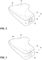
- FIG. 2 is a rear top perspective view of the roof-mounted antenna and imager module of FIG. 1 ;
- FIG. 3 is a rear top perspective view of the roof-mounted antenna and imager module of FIG. 1 with the imager module hidden from view;
- FIG. 4 is a side elevational view of the roof-mounted antenna and imager module of FIG. 1 ;
- FIG. 5 is a side elevational view of the roof-mounted antenna and imager module of FIG. 4 with the imager module hidden from view;
- FIG. 6 is a top plan view of the roof-mounted antenna and imager module of FIG. 1 ;
- FIG. 7 is a side elevational cross-sectional view of the roof-mounted antenna and imager module of FIG. 1 taken at line VII-VII;
- FIG. 7A is a side elevational view of a louvered film, as shown in area VIIA.
- FIG. 8A is a front perspective view of a center high mount stop light of a vehicle having a cover disposed over an imager of the present disclosure
- FIG. 8B is another front perspective view of the center high mount stop light of a vehicle having a cover disposed over an imager of the present disclosure
- FIG. 8C is another front perspective view of the center high mount stop light of a vehicle having a cover disposed over an imager of the present disclosure
- FIG. 9A is a rear elevational view of a vehicle with a brake light including a cover extending over an imager module;
- FIG. 9B is a rear elevational view of a vehicle with a brake light including a cover extending over an imager module;
- FIG. 9C is another rear elevational view of a vehicle with a brake light including a cover extending over an imager module;
- FIG. 10 is a side schematic view of a concealing assembly of the present disclosure in the form of a lens cover
- FIG. 11 is an electric circuit diagram in block form of the switchable lens cover of the present disclosure.
- FIG. 12 is an electric circuit diagram in schematic form of an example of the switchable lens cover shown in FIG. 11 ;
- FIG. 13 is a flowchart illustrating an electro-optic control routine performed by a controller of the imager module as shown in FIG. 11 .
- the terms “upper,” “lower,” “right,” “left,” “rear,” “front,” “vertical,” “horizontal,” and derivatives thereof shall relate to the invention as oriented in FIG. 1 .
- the term “front” shall refer to the surface of the device closer to an intended viewer of the device, and the term “rear” shall refer to the surface of the device further from the intended viewer of the device.
- the invention may assume various alternative orientations, except where expressly specified to the contrary.
- the specific devices and processes illustrated in the attached drawings and described in the following specification are simply exemplary embodiments of the inventive concepts defined in the appended claims. Hence, specific dimensions and other physical characteristics relating to the embodiments disclosed herein are not to be considered as limiting, unless the claims expressly state otherwise.
- the reference numeral 10 generally designates an imager lens cover for a vehicle 12 that includes a cover 14 disposed proximate an imager lens 16 .
- the cover 14 is configured to allow an imager 20 to capture image data 22 through the cover 14 .
- the cover 14 is operable between a first condition ( FIG. 3A ), wherein the imager 20 is generally visible through the cover 14 , and a second condition ( FIG. 3B ), wherein the imager 20 is generally concealed from view by the cover 14 .
- imagers including cameras, sensors, etc.
- vehicle manufacturers are utilizing more imagers than ever before in an effort to move the industry toward semiautonomous and fully autonomous vehicles.
- the appearance of the imagers can be unsightly.
- the concepts set forth herein address concealability issues.
- the cover 14 may include electro-optic functionality which can absorb, reflect, and/or scatter light, thereby obscuring the visibility of the imager 20 .
- the concealing cover 14 may be configured as part of a lens cover, or as part of a body panel.
- the cover 14 includes an electro-optic device that is positioned within a housing 30 of a vehicle antenna 32 .
- the cover 14 is disposed proximate the imager lens 16 and conceals the imager lens 16 from view outside of the vehicle 12 .
- the cover 14 may include a light absorbing, reflecting, and/or scattering liquid crystal device or electrochromic material.
- the cover 14 may incorporate an electro-optic device in the form of an electrochromic device that absorbs light in the visible spectrum.
- the cover 14 may include a concealing device in the form of a light absorbing device, such as a suspended particle device, when activated ( FIG. 3 ) and does not absorb light ( FIG. 4 ) when deactivated.
- a liquid crystal cell can be positioned in or on the cover 14 proximate the imager lens 16 .
- dimming liquid crystal devices include reflective cholesteric liquid crystal devices, twisted-nematic (TN) liquid crystal devices, and guest-host liquid crystal devices.
- a reflective cholesteric liquid crystal cell could be used to reflect light and prevent light from reaching the imager 20 .
- the reflective properties of a reflective cholesteric liquid crystal device will also provide reflection of ambient light. This reflective property will improve the concealment of the imager 20 by increasing the system contrast.
- the liquid crystal cell can be used in combination with absorbing or reflecting polarizers.
- the liquid crystal device may be used to block light going into or out of the imager 20 in one state, and will allow polarized light to pass through the cover 14 in the opposite state.
- the first polarizer may be positioned in the cover 14 proximate a liquid crystal device and would have the same transmission orientation as with the second polarizer positioned behind the liquid crystal cell. In this instance, the system the liquid crystal device would rotate the light 90 degrees and would block light entering the cover 14 when the concealing device of the cover 14 was nonpowered.
- the polarizers When the polarizers are positioned such that they will block both polarization orientations when there is no power, the imager 20 will be hidden behind the cover 14 ( FIGS. 3 and 5 ) when the vehicle 12 is off and would not need to be powered to achieve concealment.
- the polarizers could be absorbing polarizers or reflective polarizers. If one or more reflective polarizers are used, the concealment device of the cover 14 would be somewhat reflective in the off state, and would help to hide the imager 20 .
- the concealment device of the cover 14 may be a TN liquid crystal cell with at least one reflective polarizer with the concealment device tipped so that when observed, the concealment device appears to reflect a color that is consistent with the vehicle paint or a color of the surrounding surface on the vehicle 12 . If the device is on a roof of the vehicle 12 , a top of the concealment device of the cover 14 could be tipped down so a typical observer would be likely to perceive the concealment device of the cover 14 to have the same color tone as the color tone of the paint of the vehicle 12 roof ( FIG. 1 ).
- the concealment device of the cover 14 with reflectance may result in double images or unwanted reflections within the structure.
- the liquid crystal device using a TN liquid crystal cell one configuration would be to put an absorbing polarizer near the imager 20 and a reflective polarizer on the opposite side of the liquid crystal cell. In this instance, the reflection from the reflective polarizer would not interfere with the image data 22 collected by the imager 20 since any light reflected back toward the imager 20 off of the reflective polarizer would be aligned with the absorbing axis of the absorbing polarizer.
- the additional substrate may contain UV-blocking material to protect the polarizer.
- an electrochromic device or suspended particle device in the cover 14 proximate the imager lens 16 to provide light attenuation.
- the electrochromic device or suspended particle device may form part of the cover 14 .
- a dimming device such as an electrochromic device, could be used to reduce the overall light that reaches the imager 20 . It is generally contemplated that the electrochromic device or suspended particle device may be able to be controlled over a wide range of transmission.
- a light scattering liquid crystal system that may be used to obstruct the view of the imager 20 .
- One such light scattering device may be based on a polymer dispersed liquid crystal (PDLC). It is also generally contemplated that a light scattering device such as a PDLC device and electrochromic device may be used in conjunction.
- the electrochromic device could be laminated to the liquid crystal device. Alternatively, the electrochromic device and the liquid crystal device could share a common substrate.
- an electrochromic device with memory will be particularly advantageous for imager concealment systems designed to conceal the imager 20 when the vehicle is parked.
- an electrochromic device may be utilized having a low end transmission of 10 percent and measuring at less than 12 percent after four hours, unpowered at open circuit. The same electrochromic device may have a high-end transmission greater than 50 percent.
- a louvered film 40 may also obscure the view of the imager 20 without darkening.
- the louvered film 40 may be positioned to obstruct the view from the anticipated viewing angle. That angle would vary depending on the position of the imager 20 .
- the imager 20 may be positioned on top of the vehicle and would have a louver orientation to prevent viewing of the imager 20 from below.
- An imager positioned low on the vehicle may have a louver which conceals the imager 20 when viewed from above.
- a microdot ablation in an otherwise opaque coating proximate the imager lens 16 may allow enough light through for the imager 20 to function while still hiding the imager 20 .
- the opaque coating is a reflective coating, the imager 20 may be difficult to see during the day when ambient light would reflect off of the reflective surface. At night the imager 20 would remain hidden as the result of the partial light transmission of the coating in both directions.
- a top portion of the vehicle 12 is illustrated having a center high mount stop light (CHMSL) 50 .
- the imager 20 is disposed behind the cover 14 formed as part of the CHMSL 50 .
- the imager 20 is configured to collect the image data 22 from behind the vehicle 12 .
- the cover 14 may be configured to conceal the imager lens 16 by darkening (via any of the manners disclosed above), such that the imager lens 16 is not visible from outside of the vehicle 12 . In the darkened state, the cover 14 will appear as a dark square on the body panel or CHMSL 50 of the vehicle 12 .
- the cover 14 can be configured to appear to have a color tone that matches or nearly matches the color tone of the paint of the body panel or CHMSL 50 of the vehicle 12 .
- the imager 20 can also be used in or on a brake light 60 of the vehicle 12 .
- the imager 20 collects the image data 22 through a rear windshield 62 of the vehicle 12 .
- the imager 20 may be visible, as shown in FIG. 9A .
- the imager lens 16 may be hidden from view by the cover 14 , which may appear as a darkened area on the brake light 60 .
- the darkened state may be configured to match closely with the hue or general color of the brake light 60 , such that the imager 20 is generally not observable, nor is the cover 14 readily discernible relative to its surroundings.
- the electro-optic cell 102 may include an electro-optic material 103 , such as an electrochromic medium, for concealing an imager 104 .
- the electro-optic cell 102 may include a front substrate 101 defining a first surface 101 a and a second surface 101 b .
- the electro-optic cell 102 also includes a rear substrate 108 defining a third surface 108 a and a fourth surface 108 b . Seals 105 are disposed between the front substrate 101 and the rear substrate 108 .
- the electro-optic material 103 is sealed between the seals 105 and the front and rear substrates 101 , 108 .
- the concealing assembly 100 includes a masking layer 106 on the fourth surface 108 of the electro-optic cell 102 .
- the masking layer 106 defines an aperture 110 for the imager 104 and blocks viewing of other portions of the imager 104 or the imager housing when the electro-optic cell 102 is in a clear state. When the electro-optic cell 102 is clear, the imager 104 can view through the aperture 110 .
- the electro-optic material 103 absorbs and/or reflects at least 75 percent, at least 80 percent, or at least 90 percent of the visible light and substantially reduces the visibility of the masking layer 106 or the imager 104 .
- the transmission level of the electro-optic cell 102 can be varied from the clear state of greater than 60 percent visible light transmission to less than one percent transmission in the low transmission state.
- the total light reflecting off of the concealing assembly 100 is generally considered color neutral.
- the C* (chroma) of the concealing assembly 100 is less than 15 in the low transmission state, and may be less than 10 (when measured in the L*C*h color space). If the concealing assembly 100 has C* greater than 15, the hue may have a value of h between about 210 degrees and 280 degrees. In this range of hue, the color will appear generally blue while avoiding more pronounced and typically more objectionable green or red colors.
- h may be between 210 degrees and 280 degrees.
- the visible light transmission in the high transmission state is 63 percent and the low transmission state has 0.5 percent transmission with a C* of 7.6.
- the low end transmission range may extend from 15 percent to less than one percent.
- a continuous range of dimming between the clear state and the fully darkened state is possible and may be used to make adjustments to the amount of visible light reaching the imager 104 . In some situations, it may be advantageous to dim the electro-optic cell 102 when the ambient conditions are very bright.
- the concealing assembly 100 may be reflecting, absorbing, or scattering visible light to conceal the imager 104 when the vehicle 12 is parked. Concealing assemblies 100 that draw current in the darkened state could, over time, drain the battery of the vehicle 12 . There are a number of systems that can maintain low specular transmission with little or no power. Many liquid crystal configurations can maintain a darkened condition when in the off state. Some electrochromic systems can also maintain low transmission with little to no power. A concealing assembly 100 with less than 5 mW of power consumption in the low transmissive state may be acceptable. Power consumption less than 3 mW, 2 mW, or 1 mW may also be utilized.
- an electro-optic element is used as the lens cover to hide an imager, the electro-optic element should clear fast enough to give a driver sufficient visibility behind the car. If an electro-optic element clears too slowly, the driver may not be able to see what they need to see, and this may become a safety concern. This is particularly a problem when the camera is being used at night when there is very little illumination behind the vehicle.
- an electro-optic or electrochromic element that is used for concealing a rearward-facing camera obtaining rearward vision within 5 seconds or less is significant since a driver may enter the vehicle, start the vehicle, and begin backing up within a matter of 2-3 seconds. It is preferred that a dimming lens cover would be sufficiently cleared in 2 seconds. To properly conceal a camera, it is found that a transmission below 15 percent may be sufficient to obtain reasonable concealment and a transmission below 12 percent is more preferred. At a transmission of 15 percent or less, there is minimal light reaching the camera. At night there may not be enough light to back up safely. An electro-optic element that clears to 40 percent or more within 2 seconds will greatly increase visibility before the driver starts to move backward. If the electro-optic device does not clear fast enough, other methods will be needed.
- One possible solution to the nighttime visibility issue is to keep the electro-optic element clear when it is dark outside the vehicle. Whenever it is dark, the visibility of the camera is not a concern, so there is no need to conceal the camera. It is important to monitor light levels without causing a significant drain on the vehicle's battery. Less than 1 mW should be used to monitor the light levels. Less than 250 ⁇ W is preferred.
- an electro-optic element is used to conceal a rearward-facing camera on a vehicle.
- An electro-optic element may be used which dims below 15 percent and clears to greater than 40 percent.
- a controller 120 ( FIG. 11 ) for the electro-optic element 102 is in communication with a light sensor subsystem 125 on the vehicle that monitors ambient light levels.
- the light sensor subsystem 125 sends a signal to the controller 120 to cause the electro-optic element 102 to clear when ambient light levels are below a specified first threshold level.
- the light sensor subsystem sends a signal to the controller 120 to cause the electro-optic element 102 to darken when the ambient light levels are above a specified second threshold level.
- the first and second threshold levels may be the same or may be different to provide a hysteresis so that the electro-optic element is not switched back and forth when the ambient light level is at a particular threshold level.
- the controller 120 is configured to receive a signal when the vehicle ignition is on (vehicle is running) and to respond to such an ignition signal by clearing the electro-optic element 102 so long as the ignition signal is received whenever the ambient light level is above the second threshold level. If the ambient light level is below the first threshold level, the electro-optic element 102 will already be clear and will remain clear until such time that the ambient light level is above the second threshold level.
- FIG. 12 shows an example of the switchable lens cover circuit shown in FIG. 11 .
- a connector 150 is connected to the vehicle 12V battery so that it is provided power regardless of whether the vehicle ignition is on or off.
- the 12V power 152 is passed through a filter 154 to a first buck converter 156 , which converts the 12V power 152 to 1.2V.
- the 1.2V output then passes through a conditioning circuit 158 before being supplied to the electro-optic element 102 , which in this particular example, may be an electrochromic element.
- the 1.2V output may be selectively supplied to the electro-optic element 102 by enabling/disabling the first buck converter 156 .
- the controller 120 may be coupled to the first buck converter 156 via the output EL_EN on output pin RA 1 to selectively enable or disable the first buck converter from supplying the 1.2 V power to the electro-optic element 102 .
- the control routine 130 for this function is described below with reference to FIG. 13 .
- the controller 120 may also force the electro-optic element 102 to clear by sending a signal via output EL_CLR from output pin RA 2 to a switch 160 that creates a short to ground across electro-optic element 102 . This speeds the clearing of the electro-optic element 102 .
- a second buck converter 162 is provided to convert the 12V power 152 to a voltage vdd suitable for powering the controller 120 and the light sensor subsystem 125 .
- the first and second buck converters 156 and 162 have a low standby current and provide the advantage of efficiently converting the voltages while minimizing power consumption. This is advantageous since this circuit operates off the vehicle battery while minimizing current draw on the battery. Further, the buck converters do not require much protection up front, which further reduces power consumption and cost.
- the light sensor subsystem 125 may include a light sensor 170 , a conditioning circuit 164 , and a switch 166 .
- the input/output of the light sensor 170 is coupled to the controller 120 so that the controller 120 may receive the output from the light sensor 170 .
- the controller 120 may optionally control the sensitivity of the light sensor 170 .
- the switch 166 is provided to selectively provide power to the light sensor 170 under control of the controller 120 . This way the controller 120 can periodically supply power to the light sensor 170 so as to limit the power drain by the light sensor 170 .
- the controller 120 may average the light sensor readings.
- a moving average of the light sensor readings may be used whereby 1/16 of the value of the previous average is subtracted from the previous average and 1/16 of the new reading is added to arrive at the new average.
- the pin marked DAVESTREAM is a bidirectional I/O line which can be used for diagnostics or to provide input from the vehicle to override or modify the response to the light sensor.
- An electro-optic element control routine 130 is shown in FIG. 13 .
- the routine 130 begins with the controller 120 determining if the ambient light level is below the first threshold level (indicating nighttime light conditions) in step 132 . If the ambient light level is below the first threshold level, the controller 120 changes (or maintains) the electro-optic element 102 in the clear state in step 134 before returning to step 132 . If the ambient light level is not below the first threshold level, the controller 120 determines in step 136 if the vehicle ignition is on.
- the controller 120 changes (or maintains) the electro-optic element 102 in the clear state in step 138 before returning to step 132 . If the vehicle ignition is not on, the controller 120 determines in step 140 whether the ambient light level is above the second threshold level (indicating daytime light conditions). If the ambient light level is not above the second threshold level, the controller 120 returns to step 132 . If the ambient light level is above the second threshold level, the controller 120 changes (or maintains) the electro-optic element 102 in the dimmed state in step 142 before returning to step 132 .
- the second threshold level indicating daytime light conditions
- the circuit described above with respect to FIGS. 11-13 may also be used to control electrochromic windows 126 of the vehicle 12 .
- some windows of the vehicle typically cannot be tinted as dark as the rest of the windows.
- the controller 120 may thus further control the transmissive state of electrochromic windows 126 of the vehicle 12 , wherein the controller 120 controls the electrochromic windows 126 to be in a dimmed state when the vehicle ignition is off and the ambient light level is above the second threshold level and controls the electrochromic windows 126 to be in at least a partially clear state when the ambient light level is below a first threshold level or when the vehicle ignition is on.
- the controller 120 clears the electro-optic element 102 when the vehicle ignition is on so that the electro-optic element 102 is clear whenever the imager 104 is capturing images.
- the electro-optic element 102 dimmed when the vehicle ignition is on.
- the electro-optic element 102 may be dimmed to increase the dynamic range of the imager 104 .
- color shifts may be introduced by the electro-optic element 102 when in the dimmed state. For many electrochromic elements, these color shifts will be towards the blue and/or green region of the visible spectrum. These color shifts may be compensated using auto white balance adjustments.
- Another approach is to measure the open circuit voltage of the electro-optic element 102 to determine the extent of dimming and hence the color shift created by the electro-optic element. The color shift may then be corrected through image processing of the image data.
- Yet another solution would be to construct the electro-optic element 102 as an electrochromic element having a color neutral electrochromic medium as disclosed in U.S. Pat. No. 6,020,987, the entire disclosure of which is incorporated herein by reference. By using such a color neutral electrochromic medium, the element will transition from the clear to the fully dimmed state and back without imposing any color shift.
- An infrared (IR) absorbing electrochromic medium may be used in the electro-optic element 102 so that the lens cover functions as an IR cut filter when dimmed.
- the electro-optic element 102 may be dimmed during daytime conditions even when the vehicle is moving so that the electro-optic element 102 blocks IR radiation from reaching the imager 104 , which may affect the color sensed by the imager.
- the electro-optic element may be cleared so that it no longer blocks IR radiation and allows the imager 104 to receive the IR radiation, which enhances the sensitivity of the imager 104 thus providing greater night vision.
- An example of an electrochromic medium having such IR absorbing capabilities is disclosed in U.S. Pat. No. 6,193,912, the entire disclosure of which is incorporated herein by reference.
- the switchable lens cover is described as an electro-optic element controlled as a function of the output of a light sensor, a photochromic element may be used in place of the electro-optic element.
- Photochromic elements can change from a low light transmission state to a high light transmission state when exposed to light. The use of a photochromic element would provide the advantage of not having an electrical control circuit and hence not drawing power from the vehicle battery.
- the term “coupled” in all of its forms, couple, coupling, coupled, etc. generally means the joining of two components (electrical or mechanical) directly or indirectly to one another. Such joining may be stationary in nature or movable in nature. Such joining may be achieved with the two components (electrical or mechanical) and any additional intermediate members being integrally formed as a single unitary body with one another or with the two components. Such joining may be permanent in nature or may be removable or releasable in nature unless otherwise stated.
- elements shown as integrally formed may be constructed of multiple parts or elements shown as multiple parts may be integrally formed, the operation of the interfaces may be reversed or otherwise varied, the length or width of the structures and/or members or connector or other elements of the system may be varied, the nature or number of adjustment positions provided between the elements may be varied.
- the elements and/or assemblies of the system may be constructed from any of a wide variety of materials that provide sufficient strength or durability, in any of a wide variety of colors, textures, and combinations. Accordingly, all such modifications are intended to be included within the scope of the present innovations. Other substitutions, modifications, changes, and omissions may be made in the design, operating conditions, and arrangement of the desired and other exemplary embodiments without departing from the spirit of the present innovations.
Landscapes
- Physics & Mathematics (AREA)
- Engineering & Computer Science (AREA)
- General Physics & Mathematics (AREA)
- Nonlinear Science (AREA)
- Optics & Photonics (AREA)
- Multimedia (AREA)
- Signal Processing (AREA)
- Mathematical Physics (AREA)
- Chemical & Material Sciences (AREA)
- Crystallography & Structural Chemistry (AREA)
- Mechanical Engineering (AREA)
- Theoretical Computer Science (AREA)
- Computing Systems (AREA)
- Electrochromic Elements, Electrophoresis, Or Variable Reflection Or Absorption Elements (AREA)
- Studio Devices (AREA)
Abstract
Description
Claims (18)
Priority Applications (1)
| Application Number | Priority Date | Filing Date | Title |
|---|---|---|---|
| US16/407,818 US11307485B2 (en) | 2018-05-09 | 2019-05-09 | Switchable imager lens cover |
Applications Claiming Priority (3)
| Application Number | Priority Date | Filing Date | Title |
|---|---|---|---|
| US201862668962P | 2018-05-09 | 2018-05-09 | |
| US201862685426P | 2018-06-15 | 2018-06-15 | |
| US16/407,818 US11307485B2 (en) | 2018-05-09 | 2019-05-09 | Switchable imager lens cover |
Publications (2)
| Publication Number | Publication Date |
|---|---|
| US20190346742A1 US20190346742A1 (en) | 2019-11-14 |
| US11307485B2 true US11307485B2 (en) | 2022-04-19 |
Family
ID=68464610
Family Applications (1)
| Application Number | Title | Priority Date | Filing Date |
|---|---|---|---|
| US16/407,818 Active 2040-04-19 US11307485B2 (en) | 2018-05-09 | 2019-05-09 | Switchable imager lens cover |
Country Status (4)
| Country | Link |
|---|---|
| US (1) | US11307485B2 (en) |
| EP (1) | EP3790767B1 (en) |
| CN (1) | CN112188974B (en) |
| WO (1) | WO2019215677A1 (en) |
Families Citing this family (10)
| Publication number | Priority date | Publication date | Assignee | Title |
|---|---|---|---|---|
| WO2020075097A1 (en) * | 2018-10-09 | 2020-04-16 | Gentex Corporation | Camera concealment using photochromics |
| WO2020157726A1 (en) | 2019-02-01 | 2020-08-06 | Gentex Corporation | Active infrared illumination for enhancing rear vision from a vehicle |
| EP4351915A1 (en) * | 2021-06-09 | 2024-04-17 | Volta Charging, LLC | Kiosk having a camera occluded by a photochromic cover |
| FR3124609A1 (en) * | 2021-06-25 | 2022-12-30 | Valeo Vision | Optical module comprising a camera and an opaque element to absorb light |
| GB2611285A (en) * | 2021-09-09 | 2023-04-05 | Aptiv Tech Ltd | Camera assembly |
| DE102022102196A1 (en) | 2022-01-31 | 2023-08-03 | Ford Global Technologies, Llc | Cover for a camera lens, system and vehicle |
| JP2024065736A (en) * | 2022-10-31 | 2024-05-15 | キヤノン株式会社 | Imaging device, control method, program, and storage medium |
| US12244935B2 (en) * | 2022-11-21 | 2025-03-04 | Apollo Autonomous Driving USA LLC | On-board tuning of image signal processor for cameras of autonomous vehicles |
| TWI852486B (en) * | 2023-04-20 | 2024-08-11 | 群光電子股份有限公司 | Vehicle image recognition module |
| US12509018B2 (en) * | 2023-05-12 | 2025-12-30 | Ava-Elizabeth Francis BELL | Systems and methods for preventing car theft |
Citations (81)
| Publication number | Priority date | Publication date | Assignee | Title |
|---|---|---|---|---|
| US3659307A (en) | 1969-07-22 | 1972-05-02 | Constantine K Vitou | Automobile headlight cleaning system |
| US4063258A (en) | 1976-07-15 | 1977-12-13 | Allen Robert H | Spotlight mounted camera for vehicles |
| US4410563A (en) | 1982-02-22 | 1983-10-18 | The United States Of America As Represented By The Secretary Of The Navy | Repellent coatings for optical surfaces |
| US4621785A (en) | 1984-11-23 | 1986-11-11 | Embra Productions Ltd. | Camera mount |
| US4699478A (en) | 1986-02-24 | 1987-10-13 | Tsui Yu Ming | Self-cleaning rearview mirror |
| US4736218A (en) | 1985-10-24 | 1988-04-05 | M.S.E. Engineering Systems Ltd. | Camera support and housing |
| US5068770A (en) | 1990-09-05 | 1991-11-26 | Baziuk Maurice W | Self-cleaning lens shield for headlights |
| US5121200A (en) | 1990-07-06 | 1992-06-09 | Choi Seung Lyul | Travelling monitoring system for motor vehicles |
| US5140455A (en) | 1989-11-29 | 1992-08-18 | Donnelly Corporation | High performance electrochemichromic solutions and devices thereof |
| US5315333A (en) | 1993-06-01 | 1994-05-24 | Michael Nash | Camera lens shield |
| US5418567A (en) | 1993-01-29 | 1995-05-23 | Bayport Controls, Inc. | Surveillance camera system |
| US5619036A (en) | 1994-04-12 | 1997-04-08 | Hughes Electronics | Low cost night vision camera for vehicles and mounting thereof |
| US5760828A (en) | 1994-06-03 | 1998-06-02 | Idesa Accesorios, S.A. | Back-vision system for vehicles |
| US5761556A (en) | 1993-12-01 | 1998-06-02 | Canon Kabushi Kaisha | Optical apparatus |
| US5833101A (en) | 1997-08-28 | 1998-11-10 | Watkins; D. Scott | Camera mount |
| US5910854A (en) | 1993-02-26 | 1999-06-08 | Donnelly Corporation | Electrochromic polymeric solid films, manufacturing electrochromic devices using such solid films, and processes for making such solid films and devices |
| EP1006486A2 (en) | 1998-11-30 | 2000-06-07 | Tuner Corporation | Car-mounted image recording system |
| US6138319A (en) | 1998-11-04 | 2000-10-31 | Benoit; Robert J. | Cover and wiper for a rear vehicle light |
| US6333759B1 (en) | 1999-03-16 | 2001-12-25 | Joseph J. Mazzilli | 360 ° automobile video camera system |
| EP1227683A1 (en) | 1999-10-12 | 2002-07-31 | Matsushita Electric Industrial Co., Ltd. | Monitor camera, method of adjusting camera, and vehicle monitor system |
| US6536961B1 (en) | 2000-10-12 | 2003-03-25 | Raytheon Company | Camera system |
| US6607606B2 (en) | 2001-04-03 | 2003-08-19 | Hewlett-Packard Development Company, L.P. | Self-cleaning lens shield |
| US6619806B2 (en) | 2000-05-24 | 2003-09-16 | Nikon Corporation | Shielding device |
| US6731867B1 (en) | 2000-02-20 | 2004-05-04 | Spintech Technologies, Ltd. | Lens protection mechanism |
| US20050275738A1 (en) | 2004-06-10 | 2005-12-15 | Pentax Corporation | Digital camera and cleaning apparatus therefor |
| US20060171704A1 (en) | 2002-11-14 | 2006-08-03 | Bingle Robert L | Imaging system for vehicle |
| US7111996B2 (en) | 2001-12-20 | 2006-09-26 | Robert Bosch Gmbh | Stereo camera arrangement in a motor vehicle |
| US20060238318A1 (en) | 2003-04-01 | 2006-10-26 | Brouwer Stefan F | Wing mirror unit and actuator |
| US20060256459A1 (en) | 2003-07-29 | 2006-11-16 | Valeo Systemes D'essuyage | Rear viewing device for an automobile |
| EP1529688B1 (en) | 2003-11-04 | 2007-02-14 | Hella KGaA Hueck & Co. | Camera arrangement for motor vehicles |
| US20070132610A1 (en) | 2003-10-23 | 2007-06-14 | Stevan Guernalec | Mounting of a rearview camera in a protection housing with a view window |
| US7245207B1 (en) | 2006-01-20 | 2007-07-17 | Intellectual Solutions, Inc. | Camera and display device for use with vehicles |
| US20070182817A1 (en) | 2006-02-07 | 2007-08-09 | Donnelly Corporation | Camera mounted at rear of vehicle |
| US7255451B2 (en) | 2002-09-20 | 2007-08-14 | Donnelly Corporation | Electro-optic mirror cell |
| US7265656B2 (en) | 2002-04-19 | 2007-09-04 | Donnelly Corporation | Vehicle imaging system |
| US20070223899A1 (en) | 2006-03-23 | 2007-09-27 | Jody Snow | Passive wiper assembly |
| US20070236569A1 (en) | 2006-03-31 | 2007-10-11 | Colitec Co., Ltd. | Car-use camera |
| US7310177B2 (en) | 2002-09-20 | 2007-12-18 | Donnelly Corporation | Electro-optic reflective element assembly |
| US20080007645A1 (en) * | 2006-07-07 | 2008-01-10 | Mccutchen David | Active mask for electronic imaging system |
| US7355629B2 (en) | 2002-07-29 | 2008-04-08 | Lang Mekra North America, Llc | Internally mounted, movable camera for vehicles |
| KR20080042418A (en) | 2006-11-10 | 2008-05-15 | 두산인프라코어 주식회사 | Heavy Equipment Camera Protector |
| US7387454B2 (en) | 2004-09-22 | 2008-06-17 | Murakami Corporation | Camera |
| US20080212189A1 (en) | 2005-05-16 | 2008-09-04 | Donnelly Corporation | Vehicle Mirror Assembly With Indicia At Reflective Element |
| US7448812B2 (en) | 2004-05-27 | 2008-11-11 | Heibel Thomas S | Camera mount |
| US20080304819A1 (en) | 2007-06-08 | 2008-12-11 | Sony Ericsson Mobile Communications Ab | Thin active camera cover for an electronic device |
| US7499100B2 (en) | 2004-10-06 | 2009-03-03 | Honda Motor Co., Ltd. | Structure for attaching stereoscopic camera in vehicle |
| US20090122141A1 (en) | 2007-11-09 | 2009-05-14 | Akihiro Nakamura | Camera mounting structure, camera mounting method and exterior panel component of a vehicle |
| KR100909368B1 (en) | 2008-06-11 | 2009-07-24 | 박영한 | Vehicle rear surveillance camera installation structure |
| US7579939B2 (en) | 1998-01-07 | 2009-08-25 | Donnelly Corporation | Video mirror system suitable for use in a vehicle |
| US20090250533A1 (en) | 2008-04-03 | 2009-10-08 | Denso Corporation | Washer nozzle-equipped camera apparatus and washer nozzle |
| US7609961B2 (en) | 2006-04-11 | 2009-10-27 | Park Eric S | Vehicle camera |
| US7630624B2 (en) | 2005-09-30 | 2009-12-08 | Hon Hai Precision Industry Co., Ltd. | Digital camera module with focusing function |
| US20100118145A1 (en) | 2008-11-13 | 2010-05-13 | Laura Betham | Camera for Vehicle |
| US7813639B2 (en) | 2005-04-20 | 2010-10-12 | Autonetworks Technologies, Ltd. | Camera cover |
| US20100277379A1 (en) | 2005-11-10 | 2010-11-04 | Laird Technologies, Inc. | Interchangeable slidably mountable fins for antenna assemblies |
| US7881496B2 (en) | 2004-09-30 | 2011-02-01 | Donnelly Corporation | Vision system for vehicle |
| US7883064B2 (en) | 2007-12-31 | 2011-02-08 | Audiovox Corporation | Mounting bracket for a vehicle backup camera |
| US20110033663A1 (en) | 2008-05-09 | 2011-02-10 | The Regents Of The University Of California | Superhydrophobic and superhydrophilic materials, surfaces and methods |
| US20110037863A1 (en) | 2009-08-13 | 2011-02-17 | Sony Corporation | Imaging device |
| US7891886B2 (en) | 2006-10-09 | 2011-02-22 | Huf Hulsbeck & Furst Gmbh & Co. Kg | Device for a motor vehicle, comprising a rotatably mounted camera unit |
| US20110141281A1 (en) | 2009-12-11 | 2011-06-16 | Mobility Solutions and Innovations Incorporated | Off road vehicle vision enhancement system |
| US8031224B2 (en) | 2006-09-14 | 2011-10-04 | Smr Patents S.A.R.L. | Camera system, method for operation of a camera system and sensor device of a camera system |
| US8077406B2 (en) | 2007-03-20 | 2011-12-13 | Hoya Corporation | On-vehicle camera lens glass material and on-vehicle camera lens |
| US20110317298A1 (en) | 2008-10-30 | 2011-12-29 | Mci (Mirror Controls International) Netherlands B.V. | Mirror adjustment unit provided with an electric accessory |
| US8118501B2 (en) | 2009-02-10 | 2012-02-21 | Huf Hulsbeck & Furst Gmbh & Co. Kg | Device with a cover unit to protect a camera unit |
| KR101134305B1 (en) | 2010-04-12 | 2012-04-09 | (주)헤스코 | Car camera built in shark antenna |
| US20120327234A1 (en) | 2011-06-24 | 2012-12-27 | Fish Jr Richard T | Roof mounted imager module |
| KR101343814B1 (en) | 2012-10-16 | 2013-12-20 | 한국광성전자 주식회사 | Multimedia devices for vehicle intergrated antena and tuner module |
| US20140111684A1 (en) | 2012-10-18 | 2014-04-24 | Apple, Inc. | Antenna Structures and Electrical Components with Grounding |
| US20140253731A1 (en) | 2011-07-26 | 2014-09-11 | Gentex Corporation | Imaging device protector and cleaner |
| US9229104B2 (en) | 2009-04-24 | 2016-01-05 | Robert Bosch Gmbh | Sensor assembly for driver assistance systems in motor vehicles |
| US20160191863A1 (en) | 2014-12-31 | 2016-06-30 | Gentex Corporation | Rear vehicle camera |
| KR20160133076A (en) | 2015-05-11 | 2016-11-22 | 동아전장주식회사 | Camera apparatus for vehicle |
| US20170123575A1 (en) | 2015-10-30 | 2017-05-04 | Essential Products, Inc. | Optical sensors disposed beneath the display of an electronic device |
| WO2017201374A1 (en) | 2016-05-20 | 2017-11-23 | Gentex Corporation | Imager with active exposure correction |
| US9849836B2 (en) | 2014-04-24 | 2017-12-26 | Gentex Corporation | Roof mounted imager module |
| US20180091779A1 (en) | 2016-09-23 | 2018-03-29 | Gentex Corporation | Imager with wire harness connecting features |
| US10048696B2 (en) * | 2015-12-22 | 2018-08-14 | Uber Technologies, Inc. | Intelligent lens masking system for an autonomous vehicle |
| US20180244204A1 (en) * | 2017-02-28 | 2018-08-30 | Gentex Corporation | Auto switching of display mirror assembly |
| US20180284573A1 (en) * | 2017-03-30 | 2018-10-04 | Gentex Corporation | Switchable imager lens cover |
| US20190324343A1 (en) * | 2017-02-06 | 2019-10-24 | Chromera, Inc. | Polymorphic electro-optic displays |
Family Cites Families (3)
| Publication number | Priority date | Publication date | Assignee | Title |
|---|---|---|---|---|
| US6193912B1 (en) | 1998-03-03 | 2001-02-27 | Gentex Corporation | Near infrared-absorbing electrochromic compounds and devices comprising same |
| US7755720B2 (en) * | 2005-05-10 | 2010-07-13 | Live Technologies, Ltd | Electro-optical filter |
| US10310298B2 (en) * | 2016-10-25 | 2019-06-04 | GM Global Technology Operations LLC | Smart sensor-cover apparatus and methods and computer products for implementing same |
-
2019
- 2019-05-09 US US16/407,818 patent/US11307485B2/en active Active
- 2019-05-09 WO PCT/IB2019/053847 patent/WO2019215677A1/en not_active Ceased
- 2019-05-09 CN CN201980034755.4A patent/CN112188974B/en active Active
- 2019-05-09 EP EP19799844.6A patent/EP3790767B1/en active Active
Patent Citations (88)
| Publication number | Priority date | Publication date | Assignee | Title |
|---|---|---|---|---|
| US3659307A (en) | 1969-07-22 | 1972-05-02 | Constantine K Vitou | Automobile headlight cleaning system |
| US4063258A (en) | 1976-07-15 | 1977-12-13 | Allen Robert H | Spotlight mounted camera for vehicles |
| US4410563A (en) | 1982-02-22 | 1983-10-18 | The United States Of America As Represented By The Secretary Of The Navy | Repellent coatings for optical surfaces |
| US4621785A (en) | 1984-11-23 | 1986-11-11 | Embra Productions Ltd. | Camera mount |
| US4736218A (en) | 1985-10-24 | 1988-04-05 | M.S.E. Engineering Systems Ltd. | Camera support and housing |
| US4699478A (en) | 1986-02-24 | 1987-10-13 | Tsui Yu Ming | Self-cleaning rearview mirror |
| US5140455A (en) | 1989-11-29 | 1992-08-18 | Donnelly Corporation | High performance electrochemichromic solutions and devices thereof |
| US5121200A (en) | 1990-07-06 | 1992-06-09 | Choi Seung Lyul | Travelling monitoring system for motor vehicles |
| US5068770A (en) | 1990-09-05 | 1991-11-26 | Baziuk Maurice W | Self-cleaning lens shield for headlights |
| US5418567A (en) | 1993-01-29 | 1995-05-23 | Bayport Controls, Inc. | Surveillance camera system |
| US5910854A (en) | 1993-02-26 | 1999-06-08 | Donnelly Corporation | Electrochromic polymeric solid films, manufacturing electrochromic devices using such solid films, and processes for making such solid films and devices |
| US5315333A (en) | 1993-06-01 | 1994-05-24 | Michael Nash | Camera lens shield |
| US5761556A (en) | 1993-12-01 | 1998-06-02 | Canon Kabushi Kaisha | Optical apparatus |
| US5619036A (en) | 1994-04-12 | 1997-04-08 | Hughes Electronics | Low cost night vision camera for vehicles and mounting thereof |
| US5760828A (en) | 1994-06-03 | 1998-06-02 | Idesa Accesorios, S.A. | Back-vision system for vehicles |
| US5833101A (en) | 1997-08-28 | 1998-11-10 | Watkins; D. Scott | Camera mount |
| US7579939B2 (en) | 1998-01-07 | 2009-08-25 | Donnelly Corporation | Video mirror system suitable for use in a vehicle |
| US6138319A (en) | 1998-11-04 | 2000-10-31 | Benoit; Robert J. | Cover and wiper for a rear vehicle light |
| EP1006486A2 (en) | 1998-11-30 | 2000-06-07 | Tuner Corporation | Car-mounted image recording system |
| US6580373B1 (en) | 1998-11-30 | 2003-06-17 | Tuner Corporation | Car-mounted image record system |
| US6333759B1 (en) | 1999-03-16 | 2001-12-25 | Joseph J. Mazzilli | 360 ° automobile video camera system |
| EP1227683A1 (en) | 1999-10-12 | 2002-07-31 | Matsushita Electric Industrial Co., Ltd. | Monitor camera, method of adjusting camera, and vehicle monitor system |
| US6911997B1 (en) | 1999-10-12 | 2005-06-28 | Matsushita Electric Industrial Co., Ltd. | Monitoring system, camera adjusting method and vehicle monitoring system |
| US20160100084A1 (en) | 1999-11-04 | 2016-04-07 | Magna Electronics Inc. | Accessory mounting system for a vehicle |
| US7104657B2 (en) | 2000-02-20 | 2006-09-12 | Spintech Med. Ltd. | Lens protection for medical purposes |
| US6731867B1 (en) | 2000-02-20 | 2004-05-04 | Spintech Technologies, Ltd. | Lens protection mechanism |
| US6619806B2 (en) | 2000-05-24 | 2003-09-16 | Nikon Corporation | Shielding device |
| US6536961B1 (en) | 2000-10-12 | 2003-03-25 | Raytheon Company | Camera system |
| US6607606B2 (en) | 2001-04-03 | 2003-08-19 | Hewlett-Packard Development Company, L.P. | Self-cleaning lens shield |
| US7111996B2 (en) | 2001-12-20 | 2006-09-26 | Robert Bosch Gmbh | Stereo camera arrangement in a motor vehicle |
| US7265656B2 (en) | 2002-04-19 | 2007-09-04 | Donnelly Corporation | Vehicle imaging system |
| US7355629B2 (en) | 2002-07-29 | 2008-04-08 | Lang Mekra North America, Llc | Internally mounted, movable camera for vehicles |
| US7310177B2 (en) | 2002-09-20 | 2007-12-18 | Donnelly Corporation | Electro-optic reflective element assembly |
| US7255451B2 (en) | 2002-09-20 | 2007-08-14 | Donnelly Corporation | Electro-optic mirror cell |
| US20060171704A1 (en) | 2002-11-14 | 2006-08-03 | Bingle Robert L | Imaging system for vehicle |
| US7965336B2 (en) | 2002-11-14 | 2011-06-21 | Donnelly Corporation | Imaging system for vehicle |
| US20060238318A1 (en) | 2003-04-01 | 2006-10-26 | Brouwer Stefan F | Wing mirror unit and actuator |
| US20060256459A1 (en) | 2003-07-29 | 2006-11-16 | Valeo Systemes D'essuyage | Rear viewing device for an automobile |
| US20070132610A1 (en) | 2003-10-23 | 2007-06-14 | Stevan Guernalec | Mounting of a rearview camera in a protection housing with a view window |
| EP1529688B1 (en) | 2003-11-04 | 2007-02-14 | Hella KGaA Hueck & Co. | Camera arrangement for motor vehicles |
| US7448812B2 (en) | 2004-05-27 | 2008-11-11 | Heibel Thomas S | Camera mount |
| US20050275738A1 (en) | 2004-06-10 | 2005-12-15 | Pentax Corporation | Digital camera and cleaning apparatus therefor |
| US7387454B2 (en) | 2004-09-22 | 2008-06-17 | Murakami Corporation | Camera |
| US7881496B2 (en) | 2004-09-30 | 2011-02-01 | Donnelly Corporation | Vision system for vehicle |
| US7499100B2 (en) | 2004-10-06 | 2009-03-03 | Honda Motor Co., Ltd. | Structure for attaching stereoscopic camera in vehicle |
| US7813639B2 (en) | 2005-04-20 | 2010-10-12 | Autonetworks Technologies, Ltd. | Camera cover |
| US20080212189A1 (en) | 2005-05-16 | 2008-09-04 | Donnelly Corporation | Vehicle Mirror Assembly With Indicia At Reflective Element |
| US7630624B2 (en) | 2005-09-30 | 2009-12-08 | Hon Hai Precision Industry Co., Ltd. | Digital camera module with focusing function |
| US20100277379A1 (en) | 2005-11-10 | 2010-11-04 | Laird Technologies, Inc. | Interchangeable slidably mountable fins for antenna assemblies |
| US7245207B1 (en) | 2006-01-20 | 2007-07-17 | Intellectual Solutions, Inc. | Camera and display device for use with vehicles |
| US20070182817A1 (en) | 2006-02-07 | 2007-08-09 | Donnelly Corporation | Camera mounted at rear of vehicle |
| US20070223899A1 (en) | 2006-03-23 | 2007-09-27 | Jody Snow | Passive wiper assembly |
| US20070236569A1 (en) | 2006-03-31 | 2007-10-11 | Colitec Co., Ltd. | Car-use camera |
| US7609961B2 (en) | 2006-04-11 | 2009-10-27 | Park Eric S | Vehicle camera |
| US20080007645A1 (en) * | 2006-07-07 | 2008-01-10 | Mccutchen David | Active mask for electronic imaging system |
| US8031224B2 (en) | 2006-09-14 | 2011-10-04 | Smr Patents S.A.R.L. | Camera system, method for operation of a camera system and sensor device of a camera system |
| US7891886B2 (en) | 2006-10-09 | 2011-02-22 | Huf Hulsbeck & Furst Gmbh & Co. Kg | Device for a motor vehicle, comprising a rotatably mounted camera unit |
| KR20080042418A (en) | 2006-11-10 | 2008-05-15 | 두산인프라코어 주식회사 | Heavy Equipment Camera Protector |
| US8077406B2 (en) | 2007-03-20 | 2011-12-13 | Hoya Corporation | On-vehicle camera lens glass material and on-vehicle camera lens |
| US20080304819A1 (en) | 2007-06-08 | 2008-12-11 | Sony Ericsson Mobile Communications Ab | Thin active camera cover for an electronic device |
| US20090122141A1 (en) | 2007-11-09 | 2009-05-14 | Akihiro Nakamura | Camera mounting structure, camera mounting method and exterior panel component of a vehicle |
| US7883064B2 (en) | 2007-12-31 | 2011-02-08 | Audiovox Corporation | Mounting bracket for a vehicle backup camera |
| US20090250533A1 (en) | 2008-04-03 | 2009-10-08 | Denso Corporation | Washer nozzle-equipped camera apparatus and washer nozzle |
| US20110033663A1 (en) | 2008-05-09 | 2011-02-10 | The Regents Of The University Of California | Superhydrophobic and superhydrophilic materials, surfaces and methods |
| KR100909368B1 (en) | 2008-06-11 | 2009-07-24 | 박영한 | Vehicle rear surveillance camera installation structure |
| US20110317298A1 (en) | 2008-10-30 | 2011-12-29 | Mci (Mirror Controls International) Netherlands B.V. | Mirror adjustment unit provided with an electric accessory |
| US20100118145A1 (en) | 2008-11-13 | 2010-05-13 | Laura Betham | Camera for Vehicle |
| US8118501B2 (en) | 2009-02-10 | 2012-02-21 | Huf Hulsbeck & Furst Gmbh & Co. Kg | Device with a cover unit to protect a camera unit |
| US9229104B2 (en) | 2009-04-24 | 2016-01-05 | Robert Bosch Gmbh | Sensor assembly for driver assistance systems in motor vehicles |
| US20110037863A1 (en) | 2009-08-13 | 2011-02-17 | Sony Corporation | Imaging device |
| US20110141281A1 (en) | 2009-12-11 | 2011-06-16 | Mobility Solutions and Innovations Incorporated | Off road vehicle vision enhancement system |
| KR101134305B1 (en) | 2010-04-12 | 2012-04-09 | (주)헤스코 | Car camera built in shark antenna |
| US9838653B2 (en) | 2011-06-24 | 2017-12-05 | Gentex Corporation | Roof mounted imager module |
| US20120327234A1 (en) | 2011-06-24 | 2012-12-27 | Fish Jr Richard T | Roof mounted imager module |
| US20140253731A1 (en) | 2011-07-26 | 2014-09-11 | Gentex Corporation | Imaging device protector and cleaner |
| KR101343814B1 (en) | 2012-10-16 | 2013-12-20 | 한국광성전자 주식회사 | Multimedia devices for vehicle intergrated antena and tuner module |
| US20140111684A1 (en) | 2012-10-18 | 2014-04-24 | Apple, Inc. | Antenna Structures and Electrical Components with Grounding |
| US9849836B2 (en) | 2014-04-24 | 2017-12-26 | Gentex Corporation | Roof mounted imager module |
| US20160191863A1 (en) | 2014-12-31 | 2016-06-30 | Gentex Corporation | Rear vehicle camera |
| KR20160133076A (en) | 2015-05-11 | 2016-11-22 | 동아전장주식회사 | Camera apparatus for vehicle |
| US20170123575A1 (en) | 2015-10-30 | 2017-05-04 | Essential Products, Inc. | Optical sensors disposed beneath the display of an electronic device |
| US10048696B2 (en) * | 2015-12-22 | 2018-08-14 | Uber Technologies, Inc. | Intelligent lens masking system for an autonomous vehicle |
| WO2017201374A1 (en) | 2016-05-20 | 2017-11-23 | Gentex Corporation | Imager with active exposure correction |
| US20180091779A1 (en) | 2016-09-23 | 2018-03-29 | Gentex Corporation | Imager with wire harness connecting features |
| US20190324343A1 (en) * | 2017-02-06 | 2019-10-24 | Chromera, Inc. | Polymorphic electro-optic displays |
| US20180244204A1 (en) * | 2017-02-28 | 2018-08-30 | Gentex Corporation | Auto switching of display mirror assembly |
| US20180284573A1 (en) * | 2017-03-30 | 2018-10-04 | Gentex Corporation | Switchable imager lens cover |
| US20190346741A1 (en) | 2017-03-30 | 2019-11-14 | Gentex Corporation | Switchable imager lens cover |
Also Published As
| Publication number | Publication date |
|---|---|
| EP3790767A4 (en) | 2021-06-23 |
| CN112188974B (en) | 2024-04-02 |
| EP3790767A1 (en) | 2021-03-17 |
| WO2019215677A1 (en) | 2019-11-14 |
| EP3790767B1 (en) | 2025-06-25 |
| US20190346742A1 (en) | 2019-11-14 |
| CN112188974A (en) | 2021-01-05 |
Similar Documents
| Publication | Publication Date | Title |
|---|---|---|
| US11307485B2 (en) | Switchable imager lens cover | |
| US10802377B2 (en) | Switchable imager lens cover | |
| US12240384B2 (en) | Interior rearview mirror assembly with full screen video display | |
| US10913401B2 (en) | Vehicular camera module | |
| US7205524B2 (en) | Vehicle rearview mirror system having a variable reflectance control | |
| US10556490B2 (en) | Vehicle visor and system, vehicle and light blocking and display method | |
| US20110273659A1 (en) | Liquid crystal mirror with display | |
| US9978317B2 (en) | Electro-optic mirror having user-adustable dimming with visual feedback | |
| CN104742807A (en) | Intelligent external rearview mirror | |
| US10825958B2 (en) | Electro-optic device with mounted printed circuit board | |
| CN204506723U (en) | Intelligence outside rear-view mirror | |
| EP4112355A1 (en) | Method and system for operating a display device, specially in a motor vehicle |
Legal Events
| Date | Code | Title | Description |
|---|---|---|---|
| AS | Assignment |
Owner name: GENTEX CORPORATION, MICHIGAN Free format text: ASSIGNMENT OF ASSIGNORS INTEREST;ASSIGNORS:CAMMENGA, DAVID J.;NIU, XIAOXU;GEERLINGS, KURTIS L.;AND OTHERS;REEL/FRAME:049131/0312 Effective date: 20190508 |
|
| FEPP | Fee payment procedure |
Free format text: ENTITY STATUS SET TO UNDISCOUNTED (ORIGINAL EVENT CODE: BIG.); ENTITY STATUS OF PATENT OWNER: LARGE ENTITY |
|
| STPP | Information on status: patent application and granting procedure in general |
Free format text: DOCKETED NEW CASE - READY FOR EXAMINATION |
|
| STPP | Information on status: patent application and granting procedure in general |
Free format text: NON FINAL ACTION MAILED |
|
| STPP | Information on status: patent application and granting procedure in general |
Free format text: RESPONSE TO NON-FINAL OFFICE ACTION ENTERED AND FORWARDED TO EXAMINER |
|
| STPP | Information on status: patent application and granting procedure in general |
Free format text: NOTICE OF ALLOWANCE MAILED -- APPLICATION RECEIVED IN OFFICE OF PUBLICATIONS |
|
| STPP | Information on status: patent application and granting procedure in general |
Free format text: PUBLICATIONS -- ISSUE FEE PAYMENT VERIFIED |
|
| STCF | Information on status: patent grant |
Free format text: PATENTED CASE |
|
| MAFP | Maintenance fee payment |
Free format text: PAYMENT OF MAINTENANCE FEE, 4TH YEAR, LARGE ENTITY (ORIGINAL EVENT CODE: M1551); ENTITY STATUS OF PATENT OWNER: LARGE ENTITY Year of fee payment: 4 |