US11305447B2 - Pipe cutting machine with a controlled floating cutting mandrel, and cutting method - Google Patents
Pipe cutting machine with a controlled floating cutting mandrel, and cutting method Download PDFInfo
- Publication number
- US11305447B2 US11305447B2 US16/765,500 US201816765500A US11305447B2 US 11305447 B2 US11305447 B2 US 11305447B2 US 201816765500 A US201816765500 A US 201816765500A US 11305447 B2 US11305447 B2 US 11305447B2
- Authority
- US
- United States
- Prior art keywords
- cutting
- mandrel
- pipe
- sensor
- die
- Prior art date
- Legal status (The legal status is an assumption and is not a legal conclusion. Google has not performed a legal analysis and makes no representation as to the accuracy of the status listed.)
- Active, expires
Links
Images


Classifications
-
- B—PERFORMING OPERATIONS; TRANSPORTING
- B26—HAND CUTTING TOOLS; CUTTING; SEVERING
- B26D—CUTTING; DETAILS COMMON TO MACHINES FOR PERFORATING, PUNCHING, CUTTING-OUT, STAMPING-OUT OR SEVERING
- B26D3/00—Cutting work characterised by the nature of the cut made; Apparatus therefor
- B26D3/16—Cutting rods or tubes transversely
- B26D3/164—Cutting rods or tubes transversely characterised by means for supporting the tube from the inside
-
- B—PERFORMING OPERATIONS; TRANSPORTING
- B23—MACHINE TOOLS; METAL-WORKING NOT OTHERWISE PROVIDED FOR
- B23D—PLANING; SLOTTING; SHEARING; BROACHING; SAWING; FILING; SCRAPING; LIKE OPERATIONS FOR WORKING METAL BY REMOVING MATERIAL, NOT OTHERWISE PROVIDED FOR
- B23D21/00—Machines or devices for shearing or cutting tubes
- B23D21/14—Machines or devices for shearing or cutting tubes cutting inside the tube
-
- B—PERFORMING OPERATIONS; TRANSPORTING
- B23—MACHINE TOOLS; METAL-WORKING NOT OTHERWISE PROVIDED FOR
- B23D—PLANING; SLOTTING; SHEARING; BROACHING; SAWING; FILING; SCRAPING; LIKE OPERATIONS FOR WORKING METAL BY REMOVING MATERIAL, NOT OTHERWISE PROVIDED FOR
- B23D33/00—Accessories for shearing machines or shearing devices
- B23D33/02—Arrangements for holding, guiding, and/or feeding work during the operation
-
- B—PERFORMING OPERATIONS; TRANSPORTING
- B23—MACHINE TOOLS; METAL-WORKING NOT OTHERWISE PROVIDED FOR
- B23D—PLANING; SLOTTING; SHEARING; BROACHING; SAWING; FILING; SCRAPING; LIKE OPERATIONS FOR WORKING METAL BY REMOVING MATERIAL, NOT OTHERWISE PROVIDED FOR
- B23D35/00—Tools for shearing machines or shearing devices; Holders or chucks for shearing tools
- B23D35/001—Tools for shearing machines or shearing devices; Holders or chucks for shearing tools cutting members
-
- B—PERFORMING OPERATIONS; TRANSPORTING
- B26—HAND CUTTING TOOLS; CUTTING; SEVERING
- B26D—CUTTING; DETAILS COMMON TO MACHINES FOR PERFORATING, PUNCHING, CUTTING-OUT, STAMPING-OUT OR SEVERING
- B26D7/00—Details of apparatus for cutting, cutting-out, stamping-out, punching, perforating, or severing by means other than cutting
- B26D7/01—Means for holding or positioning work
- B26D2007/013—Means for holding or positioning work the work being tubes, rods or logs
Definitions
- the invention relates to a pipe cutting machine according to the preamble to claim 1 and to a method for cutting pipe sections of a pipe to size.
- the positioning through the initial pipe is additionally very susceptible to malfunction, since the holding rod can be very long, for example six to twelve metres.
- the resulting large temperature-dependent longitudinal extent and the sagging are obstructive for the exact positioning of the mandrel gap. In any case, for the shearing method it is imperative to position the mandrel gap absolutely exactly.
- a method for cutting workpieces is known from DE 2 430 608 A1.
- a support element or mandrel consisting of two elements which are separable from one another is provided, wherein one element is produced from a hardened magnetic material, the other element is made from a hardened material.
- a solenoid coil is arranged adjacent to the one element.
- a pipe cutting machine with a mandrel mounted in a floating manner is known from U.S. Pat. No. 4,889,023, in which the mandrel is positioned by means of a magnetic field.
- the object of the invention is to provide a pipe cutting machine and a method for cutting pipe sections to size which reduce the above-mentioned disadvantages.
- a pipe cutting machine should be understood here to be a pipe shearing machine.
- a pipe should preferably be understood to be a longitudinal profile which has a circular external periphery in cross-section and a circular internal periphery in cross-section and is preferably paramagnetic or diamagnetic here.
- the pipe cutting machine here comprises the already inserted pipe, from which a pipe section is to be cut to size, and a die cutter with a stationary cutting die and a movable cutting die which can be moved relative to the stationary cutting die and also a cutting mandrel which is introduced into the pipe and has a stationary mandrel and a movable mandrel which can be moved relative to the stationary mandrel.
- the cutting mandrel is arranged in the interior of the pipe during the cutting operation.
- a mandrel gap that is to say a distance between a flat end of the stationary mandrel and a flat end of the movable mandrel, is smaller than the radially lengthened die gap and is arranged along the entire circumference of the pipe inside the radially lengthened die gap, that is to say the distance between the cutting die in a fixed position and the movable cutting die.
- the cutting die is preferably driven by an eccentric drive in an eccentric movement relative to the stationary cutting die, which is a spirally increasing movement, that is to say a movement with a variable stroke. By this eccentric movement the pipe section can be cut off from the pipe.
- the movable cutting die is preferably connected to the eccentric drive; furthermore, a feed device, for example in the form of a movable gripper, is provided, which advances the pipe exactly in the pipe cutting machine by the required length for cutting to size.
- the tube is advanced step by step during the cyclical cutting operations.
- a controlled, floating cutting mandrel is arranged in the pipe, and a magnetic coupling is provided with a coupling stator arranged outside the pipe and a coupling rotor which is arranged on the stationary mandrel and interacts with the coupling stator.
- the magnetic coupling forms a magnetic field between the coupling rotor and the coupling stator.
- a movement of the magnetic field in the longitudinal direction can be controlled using control values. The movement of the magnetic field can be effected in different ways.
- a position sensor is provided with a sensor stator which is connected to the frame of the pipe cutting machine in a fixed position and a sensor rotor connected to the stationary mandrel in a fixed position, by which axial deviations of the cutting mandrel from the cutting position can be measured, and a control unit is provided which converts the deviation measurement values determined by the position sensor into the control values.
- the control values are fed to the control unit, by means of which the cutting mandrel can be returned to the cutting position.
- the invention makes use of the idea of no longer positioning the cutting mandrel by means of a rod which is guided through one or the other pipe end, but completely dispensing with this mechanical connection and instead providing the magnetic coupling, which holds the floating cutting mandrel in position, and for this purpose providing a position sensor which, in the event of displacement the magnetic coupling, measures this as a change and corrects it by means of the control unit.
- the magnetic coupling preferably has in the coupling stator a row of annular permanent magnets arranged externally around the pipe, whilst the coupling rotor, which is part of the floating cutting mandrel, likewise has a row of preferably annular permanent magnets, which are designed with opposite poles to the associated magnets of the coupling stator and so pull the cutting mandrel to a cutting position by means of a magnetic force forming through the pipe wall.
- the magnets, preferably ring magnets of the magnetic coupling and also of the position sensor can also be designed as electric magnets. Corresponding electrical connections for the coils should then be provided.
- the magnets of the floating cutting mandrel can also be designed as permanent magnets and the outer magnets of the sensor stator and coupling stator can be designed as electric magnets, from and to which electrical leads can be easily laid.
- the magnetic coupling When the magnetic coupling is formed by permanent magnets it is adjustable in the axial direction, for example by the entire housing of the coupling stator being displaceable in the axial direction.
- the magnets are electric magnets, coils can be switched so that the magnetic field shifts to and fro in the axial direction. In both cases the magnetic field of the magnetic coupling is displaceable in the axial direction in order thus to correctly orient the cutting mandrel newly or initially in its position relative to the die cutter.
- the movement of the magnetic field of the magnetic coupling is determined by control values which are determined by measurement values of the position sensor.
- the position sensor preferably has a sensor rotor which has at least two magnets spaced apart from one another in the longitudinal direction.
- the sensor stator has at least two sensor rings, each having at least two Hall effect sensors. Changing magnetic field strength are measured by the Hall effect sensors by the axial movement of the magnets in the axial longitudinal direction.
- the measurement values are determined and preferably processed and fed to the magnetic coupling as control values.
- the Hall effect sensors are advantageously connected to the control unit, the measurement values of the Hall effect sensors of a sensor ring are each assigned a sensor ring measurement value, and from changes to sensor ring measurement value differences a deviation of the cutting mandrel from the cutting position is calculated and the deviation measurement values are generated.
- Average values preferably weighted average values, can preferably be formed from the measurement values of the Hall effect sensors of a sensor ring and these are fed as sensor measurement value to the control unit.
- each sensor ring leads to a sensor ring, and in the event of movement of the cutting mandrel each sensor ring generates other sensor ring measurement values by movement of the magnets of the cutting mandrel relative to the sensor stator, and the movement of the cutting mandrel out of the cutting position can be calculated from the sensor ring measurement value differences.
- Corresponding control values are determined, and the movement of the cutting mandrel is reversed by corresponding movement of the magnetic field of the magnetic coupling.
- the object is also achieved by a method for cutting pipe sections to size of the type referred to in the introduction and having the features of claim 5 .
- a floating cutting mandrel is introduced into the pipe, the pipe is introduced into a die cutter until a cutting surface between pipe section and pipe is arranged in an extension of the die gap and the floating cutting mandrel is oriented in its axial position and moved into a cutting position in which a cutting mandrel gap is arranged inside the extension of the die gap.
- the method is suitable in particular to be carried out with one of the pipe cutting machines referred to in the introduction.
- the pipe cutting machines referred to in the introduction are all suitable for carrying out the said method or the following methods.
- a position sensor preferably measures movements of the cutting mandrel out of a cutting position and feeds measurement values to the control unit, which determines the movement measurement values and converts them into control values and feeds them to a magnetic coupling, which moves the cutting mandrel back into its cutting position.
- Measurement values are preferably measured by Hall effect sensors arranged along a measurement ring and are processed to produce a sensor ring measurement value, and the sensor ring measurement values of at least two measurement rings are determined and compared with sensor ring measurement values of a cutting position, and the movement measurement values are calculated from the comparison.
- the movement measurement values can then be converted by the control unit into the said control measurement values.
- the measurement values of the Hall effect sensors of a measurement ring are advantageously calculated by averaging the individual measurement values of the Hall effect sensors. In this case the averaging should also be weighted.
- differences between the averaged measurement values can be calculated and compared with the differences of the averaged measurement values of the cutting position, and the movement measurement values are calculated from this difference.
- FIG. 1 shows a perspective view of the die cutter, a magnetic coupling and a position sensor with an inserted pipe, in which a floating cutting mandrel is arranged
- FIG. 2 shows a sectional view of the arrangement in FIG. 1 along the line II-II in FIG. 1 , with a section of the cutting mandrel introduced into the pipe,
- FIG. 3 a shows a sectional view in FIG. 2 with deflected, movable cutting die and one pipe section cut to size from the pipe,
- FIG. 3 b shows a view of a detail in FIG. 3 a with the representation of the relative size of a cutting mandrel gap and a die cutting gap
- FIG. 4 shows a sectional view along the line IV-IV in FIG. 1 with the arrangement of six Hall effect sensors on the sensor stator
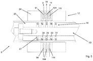
- FIG. 5 shows a functional representation of the position sensor with sensor stator and sensor rotor in the cutting position with magnetic field line indicated
- FIG. 6 shows a representation according to FIG. 5 with the cutting mandrel moved towards the left out of the cutting position and the associated magnetic field lines
- FIG. 7 shows a representation according to FIG. 5 with the cutting mandrel moved towards the right out of the cutting position with associated magnetic field lines
- FIG. 8 shows a graph of measurement values of the three sensor rings illustrated in FIGS. 5, 6 and 7 with Hall effect sensors during movement of the cutting mandrel towards the left and right out of the cutting position.
- FIG. 1 shows a part of a pipe cutting machine.
- the actual cutting operation is carried out in the pipe cutting machine by a die cutter having two co-operating cutting dies 1 , 2 .
- Cutting is also understood here as shearing.
- the die cutter comprises the stationary cutting die 1 and the movable cutting die 2 .
- the stationary cutting die 1 is arranged in a fixed position relative to a frame or housing (not illustrated) of the cutting machine even during the cutting operation or shearing operation.
- the movable cutting die 2 is movable relative to the stationary cutting die 1 parallel to a cutting plane.
- the movable cutting die 2 is driven by an eccentric drive, which is likewise not illustrated, and therefore carries out an eccentric movement about a longitudinal axis L of a pipe 3 introduced into the stationary cutting die 1 .
- the eccentric movement leads to an increasing spiral cutting movement, by which the one pipe section 3 a is sheared off from the pipe 3 .
- a magnetic coupling 6 is provided with a coupling stator 7 which is visible in FIG. 1 , placed externally around the pipe, and which interacts with a coupling rotor, not illustrated in FIG. 1 , which is arranged in the interior and is part of a floating cutting mandrel.
- FIG. 1 a position sensor 8 through which the pipe 3 is likewise inserted is arranged on the side of the magnetic coupling 6 located opposite the die cutter.
- the pipe 3 is initially guided through the position sensor 8 , then through the magnetic coupling 6 and then through the two cutting dies 1 , 2 through through-holes 1 a , 2 a provided therefor.
- the state with the pipe already inserted is illustrated in FIG. 1 .
- Three sensor rings 9 , 10 , 11 are arranged on the position sensor 8 .
- Each of the sensor rings 9 , 10 , 11 has six Hall effect sensors 91 , 92 , 93 , 94 , 95 , 96 , 101 , 102 , 103 , 104 , 105 , 106 , 111 , 112 , 113 , 114 , 115 , 116 .
- the position sensor 8 comprises a sensor stator 12 illustrated in FIG. 1 and arranged externally around the pipe 3 as well as a sensor rotor 19 designed as part of a floating cutting mandrel 13 .
- the coupling stator 7 can be arranged in a fixed position relative to the frame of the pipe cutting machine. However, it can also be designed to be movable to and fro by means of a linear motor. In the first case a control is provided which makes it possible for magnetic fields formed by the coupling stator 7 to be moved to and fro in the longitudinal direction L of the pipe 3 which corresponds to an axial direction. In the second case this movement of the magnetic field is performed by the linear motor which moves the magnetic fields in the coupling stator 7 . The movement is illustrated by the double arrow.
- FIG. 2 shows the sectional view of FIG. 1 along the line II-II.
- Both cutting dies 1 , 2 each have the cylindrical holes 1 a , 2 a of the same size with an internal diameter which corresponds to the external diameter of the pipe 3 , wherein the two holes 1 a , 2 a in
- FIG. 2 are arranged congruently, so that one end of the pipe 3 is inserted through both holes 1 a , 2 a simultaneously.
- the floating cutting mandrel 13 is already arranged in a cutting position.
- the floating cutting mandrel 13 is not led out to the exterior either at one end or the other end of the pipe 3 , in order to connect it to the frame, a guide rod or other devices of the pipe cutting machine.
- the cutting mandrel 13 is freely movable to and fro in the longitudinal direction L of the pipe 3 .
- the cutting mandrel 13 has a stationary mandrel 14 as well as a movable mandrel 16 .
- the movable mandrel 16 is designed to be movable perpendicular to the longitudinal direction L relative to the stationary mandrel 14 in all directions.
- the movable mandrel 14 absorbs the forces of the movable cutting die 2 on an inner wall face and guides them through the interior of the pipe section 3 a to be cut to size to an opposing inner wall face of the pipe sections 3 a to be cut to size, so that during a movement of the movable cutting die 2 from the top downwards, as illustrated in FIG. 3 a , the upper region and the lower region of the pipe section 3 a of the pipe are sheared off. In this case the lateral regions are initially somewhat deformed.
- FIG. 2 shows the pipe 3 in the cutting position in which the die gap 17 and the cutting mandrel gap 18 lie directly one above the other. Centre planes of the two gaps 17 , 18 coincide.
- FIG. 3 a shows the floating cutting mandrel 13 in a deflected state during the shearing operation.
- the movable mandrel 14 is deflected downwards.
- the view of a detail in FIG. 3 b shows that for carrying out the cutting movement it is significant that a die gap 17 between the stationary cutting die 1 and the movable cutting die 2 , which is approximately 0.2 mm+/ ⁇ 0.05 mm, surrounding the pipe 3 , defines a region within which a cutting mandrel gap 18 is located between the movable mandrel 16 and the mandrel 14 .
- the cutting mandrel gap here is approximately 0.01 mm+/ ⁇ 0.005 mm. Otherwise the cutting dies 1 , 2 would be damaged during shearing off.
- the position sensor 8 comprises the sensor stator 12 situated externally around the pipe and the sensor rotor 19 , which is designed as a section of the cutting mandrel 13 and is arranged on the end of the cutting mandrel 13 opposite the movable mandrel 16 .
- the position sensor 8 and the magnetic coupling 6 can also be interchanged on the cutting mandrel 13 .
- the magnetic coupling 6 consists of the coupling stator 7 , which can be arranged movably relative to the frame of the pipe cutting machine, or the magnetic fields can be movable to and fro by means of a linear motor.
- the coupling stator 7 interacts with a coupling rotor 21 , which likewise forms a section of the cutting mandrel 13 .
- the magnetic coupling is formed by two rows of magnets.
- the coupling stator 7 has a first row of ring magnets 71 , 72 arranged one behind the other, which form alternately inwardly directed north and south poles.
- the coupling rotor 21 has a second row of magnets 211 , 212 which are, however, arranged the other way round, so that a coupling behaviour is set and the cutting mandrel 13 is pulled automatically by the two magnets into the cutting position in which the magnets of the two rows of magnets assume the smallest distance from one another.
- the magnetic coupling 6 is suitable primarily for cutting non-ferromagnetic pipes which are made completely from stainless steel, brass, copper and titanium or mixtures thereof; in principle, ferromagnetic pipes 3 could also be cut if the magnets are sufficiently strong.
- the position of the magnetic coupling 6 that is to say the coupling stator 7 , spaced apart from the die cutter 1 is set with regard to the dimensions of the cutting mandrel 13 .
- slight movements can already occur due to temperature influences which act on the machine and can effect the changes in length in the range of dimensions of tenths of millimetres illustrated in FIG. 3 b , but these can hinder or even prevent the shearing operation.
- the position of the floating mandrel 13 relative to the stationary cutting die 1 in particular the position of the cutting mandrel gap 18 relative to the die gap 17 , is controlled continuously or regularly with the aid of the position sensor 8 .
- the position sensor 8 in FIG. 3 a has the three sensor rings 9 , 10 , 11 with the respective six Hall effect sensors 91 , 92 , 93 , 94 , 95 , 96 , 101 , 102 , 103 , 104 , 105 , 106 , 111 , 112 , 113 , 114 , 115 , 116 , as illustrated in the sectional view in FIG. 4 , shown on the first sensor ring 9 .
- the other sensor rings 10 , 11 are structurally identical to the first sensor ring 9 .
- each of the sensor rings 9 , 10 , 11 has two or four or even a higher number of Hall effect sensors 91 , 92 , 93 , 94 , 95 , 96 , 101 , 102 , 103 , 104 , 105 , 106 , 111 , 112 , 113 , 114 , 115 , 116 .
- at least two are necessary, which are then arranged offset by 180° in each case.
- the six Hall effect sensors 91 , 92 , 93 , 94 , 95 , 96 are shown, which are arranged offset by 60° in each case.
- the six Hall effect sensors 91 , 92 , 93 , 94 , 95 , 96 of the first sensor ring 9 are recessed in a surrounding iron ring 23 , and the sensor rings 9 , 10 , 11 are guided in a guide sleeve 24 according to FIG. 5 .
- the guide sleeve 24 has a cylindrical opening 25 which corresponds to the outer tube diameter and is inserted through the pipe 3 .
- a small clearance 26 of the size of a fraction of a millimetre is provided, so that the pipe 3 can also be inserted through the cylindrical opening 25 of the sensor stator 12 .
- an equally small clearance 26 a is provided between the pipe 3 and the permanent magnet ring 27 .
- the sensor rotor 19 is provided in the interior of the pipe 3 .
- a permanent magnet ring 27 which externally constitutes a north pole is illustrated in a sectional view in FIG. 4 .
- the permanent magnet ring 27 is fitted onto a non-magnetic, i.e. paramagnetic or diamagnetic holding rod 22 .
- An external diameter of the permanent magnet ring 27 corresponds to the internal diameter of the pipe 3 , likewise minus a small clearance of a fraction of a millimetre.
- FIG. 5 shows five permanent magnet rings 27 , 28 , 29 , 30 , 31 according to FIG. 4 .
- the interaction of the permanent magnet rings 27 , 28 , 29 , 30 , 31 of the sensor rotor 19 and the Hall effect sensors 91 , 92 , 93 , 94 , 95 , 96 , 101 , 102 , 103 , 104 , 105 , 106 , 111 , 112 , 113 , 114 , 115 , 116 of the sensor stator 12 is illustrated in FIGS. 5, 6 and 7 with associated magnetic field lines.
- Each of the Hall effect sensors 91 , 92 , 93 , 94 , 95 , 96 , 101 , 102 , 103 , 104 , 105 , 106 , 111 , 112 , 113 , 114 , 115 , 116 measures the magnetic field strength at the radially outer end of the sensor ring 9 , 10 , 11 associated with it, i.e. at the point at which the Hall effect sensors 91 , 92 , 93 , 94 , 95 , 96 , 101 , 102 , 103 , 104 , 105 , 106 , 111 , 112 , 113 114 115 , 116 according to FIG. 4 are arranged.
- FIG. 5 shows the design of the magnetic field lines in the cutting position, i.e. the position when according to FIG. 2 and FIG. 3 b the cutting mandrel gap 18 is arranged completely inside the die cutting gap 17 . It can be seen that the sensor 101 receives no signal, whilst the sensors 91 and 111 receive a relatively strong signal.
- the associated measurement values are illustrated in FIG. 8 on the zero line. In fact it is the case that the measurement values of an individual Hall effect sensor are not indicated in FIG. 8 and fed to a control unit. Since the permanent magnet rings 27 , 28 , 29 , 30 , 31 of the sensor rotor 19 are also movable perpendicularly to the longitudinal direction L through the clearance and the Hall effect sensors 91 , 92 , 93 , 94 , 95 , 96 , 101 , 102 , 103 , 104 , 105 , 106 , 111 , 112 , 113 114 115 , 116 react extremely sensitively to changes in the magnetic field strength, a weighted or simple, non-weighted average value of the Hall effect sensors 91 , 92 , 93 , 94 , 95 , 96 , 101 , 102 , 103 , 104 , 105 , 106 , 111 , 112 , 113 114 115 , 116
- FIG. 6 shows the magnetic field lines during a movement of the floating cutting mandrel 13 in the direction of the cutting die 1 . Due to the movement of the permanent magnet rings 27 , 28 , 29 , 30 , 31 a strong magnetic field is produced on the sensor ring 10 , whilst the magnetic fields decrease on the Hall effect sensors 91 , 92 , 93 , 94 , 95 , 96 , 111 , 112 , 113 114 115 , 116 of the sensor rings 9 and 11 . This is illustrated in FIG. 8 in the “ FIG. 6 ” position, which corresponds to FIG. 6 .
- FIG. 7 which corresponds to the “ FIG. 7 ” position in FIG. 8
- the cutting mandrel 13 is moved away from the cutting die 1 .
- the sensor ring 10 receives a maximum measurement signal, but in precisely the opposite direction, since the field lines have reversed their direction relative to FIG. 6 , whilst the sensor rings 9 and 11 in turn experience a weak signal, likewise in the opposite direction.
- the measurement values are likewise illustrated. In a continuous movement the three sensor rings 9 , 10 , 11 would produce a measurement value curve in sinusoidal form, as illustrated in FIG. 8 .
Landscapes
- Engineering & Computer Science (AREA)
- Mechanical Engineering (AREA)
- Life Sciences & Earth Sciences (AREA)
- Forests & Forestry (AREA)
- Manufacture Of Motors, Generators (AREA)
- Turning (AREA)
- Machine Tool Sensing Apparatuses (AREA)
- Accessories And Tools For Shearing Machines (AREA)
- Linear Motors (AREA)
- Sawing (AREA)
Abstract
Description
- 1 stationary cutting
- 1 a hole
- 2 movable cutting die
- 2 a hole
- 3 pipe
- 3 a pipe section
- 6 magnetic coupling
- 7 coupling stator
- 8 position sensor
- 9 sensor ring
- 10 sensor ring
- 11 sensor ring
- 12 sensor stator
- 13 floating cutting mandrel
- 14 stationary mandrel
- 16 movable mandrel
- 17 die gap
- 18 cutting mandrel gap
- 19 sensor rotor
- 21 coupling rotor
- 22 holding rod
- 23 iron ring
- 24 guide sleeve
- 25 cylindrical opening
- 26 clearance
- 26 a clearance
- 27 permanent magnet ring
- 28 permanent magnet ring
- 29 permanent magnet ring
- 30 permanent magnet ring
- 31 permanent magnet ring
- 71 ring magnet
- 72 ring magnet
- 91 Hall effect sensor
- 92 Hall effect sensor
- 93 Hall effect sensor
- 94 Hall effect sensor
- 95 Hall effect sensor
- 96 Hall effect sensor
- 101 Hall effect sensor
- 102 Hall effect sensor
- 103 Hall effect sensor
- 104 Hall effect sensor
- 105 Hall effect sensor
- 106 Hall effect sensor
- 111 Hall effect sensor
- 112 Hall effect sensor
- 113 Hall effect sensor
- 114 Hall effect sensor
- 115 Hall effect sensor
- 116 Hall effect sensor
- 211 ring magnet
- 212 ring magnet
- L longitudinal direction
Claims (8)
Applications Claiming Priority (3)
| Application Number | Priority Date | Filing Date | Title |
|---|---|---|---|
| DE102017127326.3A DE102017127326B3 (en) | 2017-11-20 | 2017-11-20 | Pipe cutting machine with a controlled, flying cutting mandrel |
| DE102017127326.3 | 2017-11-20 | ||
| PCT/EP2018/081508 WO2019096969A1 (en) | 2017-11-20 | 2018-11-16 | Pipe cutting machine with a controlled floating cutting mandrel, and cutting method |
Publications (2)
| Publication Number | Publication Date |
|---|---|
| US20200316696A1 US20200316696A1 (en) | 2020-10-08 |
| US11305447B2 true US11305447B2 (en) | 2022-04-19 |
Family
ID=64426888
Family Applications (1)
| Application Number | Title | Priority Date | Filing Date |
|---|---|---|---|
| US16/765,500 Active 2039-04-20 US11305447B2 (en) | 2017-11-20 | 2018-11-16 | Pipe cutting machine with a controlled floating cutting mandrel, and cutting method |
Country Status (9)
| Country | Link |
|---|---|
| US (1) | US11305447B2 (en) |
| EP (1) | EP3713702B1 (en) |
| JP (1) | JP7056996B2 (en) |
| CN (1) | CN111655413B (en) |
| CA (1) | CA3083048C (en) |
| DE (1) | DE102017127326B3 (en) |
| ES (1) | ES2954429T3 (en) |
| MX (1) | MX2020005198A (en) |
| WO (1) | WO2019096969A1 (en) |
Families Citing this family (9)
| Publication number | Priority date | Publication date | Assignee | Title |
|---|---|---|---|---|
| CN110962177B (en) * | 2019-11-27 | 2021-09-07 | 无锡品知信息科技有限公司 | A loop cutter for hose processing |
| CN112207456B (en) * | 2020-10-16 | 2022-02-15 | 重庆万重山智能科技有限公司 | Cutting module and full-automatic laser pipe cutting machine thereof |
| CN113276209B (en) * | 2021-05-31 | 2022-04-08 | 明光永信塑业科技有限公司 | Straw cutting device |
| CN113478549B (en) * | 2021-08-02 | 2023-03-24 | 苏州弗莱依格密封科技有限公司 | Rubber sealing ring cutting machine and cutting method thereof |
| KR102728207B1 (en) * | 2021-09-02 | 2024-11-11 | 한양이엔지 주식회사 | Apparatus for preventing pipe scratch |
| CN114043095B (en) * | 2021-11-11 | 2025-03-07 | 深圳市单色科技有限公司 | A femtosecond laser precision tube cutting device and control method thereof |
| CN115464701B (en) * | 2022-09-13 | 2023-09-29 | 阿格思(苏州)流体动力科技有限公司 | Hose assembly and processing equipment thereof |
| CN115709382A (en) * | 2022-11-08 | 2023-02-24 | 浙江长兴和良智能装备有限公司 | Magnetic suspension core rod device |
| CN117674529A (en) * | 2023-08-24 | 2024-03-08 | 比亚迪股份有限公司 | A primary component, linear motor, electromagnetic suspension and vehicle |
Citations (10)
| Publication number | Priority date | Publication date | Assignee | Title |
|---|---|---|---|---|
| US3567088A (en) * | 1969-06-24 | 1971-03-02 | Colorado Mfg Corp | Apparatus for shearing rigid wall tubes |
| DE2430608A1 (en) | 1973-06-27 | 1975-01-23 | Skf Kugellagerfabriken Gmbh | METHOD AND DEVICE FOR PERFORMING THE METHOD FOR CUTTING WORK PIECES OF CERTAIN LENGTH OF PROFILE MATERIAL, E.G. FROM A PIPE |
| US4470330A (en) * | 1983-02-22 | 1984-09-11 | Lindell Lennart J | Tooling assembly for an impact press |
| SU1196167A1 (en) * | 1984-11-10 | 1985-12-07 | Предприятие П/Я Р-6205 | Mandrel to pipe-cutting die |
| US4889023A (en) | 1985-10-30 | 1989-12-26 | Lhomme S.A. | Tube truncation apparatus and method |
| WO1994023876A1 (en) * | 1993-04-20 | 1994-10-27 | Nkk Corporation | Method of precisely shearing piping material and apparatus therefor |
| KR950009069Y1 (en) * | 1993-05-31 | 1995-10-19 | 김충열 | Pipe cutting device |
| DE10162135A1 (en) * | 2001-12-18 | 2003-07-10 | Global Group Holding Ag Luxemb | Hollow profile shearing unit has stops for profile end location which are also used as ejectors for sheared-off sections |
| DE102010061191A1 (en) | 2010-12-13 | 2012-06-14 | Gustav Klauke Gmbh | Method for splitting copper pipe into two pipe members that are utilized for manufacturing e.g. lug, involves arranging unconnected mandrel parts in pipe such that mandrel parts remains in pipe members after splitting process |
| WO2018054706A1 (en) | 2016-09-23 | 2018-03-29 | Rattunde & Co Gmbh | Eccentric cutting drive having a variable stroke |
Family Cites Families (9)
| Publication number | Priority date | Publication date | Assignee | Title |
|---|---|---|---|---|
| GB1411321A (en) * | 1973-06-13 | 1975-10-22 | Ti Group Services Ltd | Shearing tubes |
| JPS6311211A (en) * | 1986-03-12 | 1988-01-18 | Murao:Kk | Method and apparatus for cutting off pipe |
| JPS6311210A (en) * | 1986-06-30 | 1988-01-18 | Toshiba Corp | Pipe cutter |
| FI87898C (en) * | 1988-04-25 | 1993-03-10 | Lhomme Sa | Device for cutting pipes |
| FI88370C (en) * | 1988-04-25 | 1993-05-10 | Lhomme Sa | ROERKAPNINGSANORDNING |
| JPH04210318A (en) * | 1990-12-14 | 1992-07-31 | Masao Murakawa | Method for precise processing of pipe member |
| JPH0748335Y2 (en) * | 1993-05-31 | 1995-11-08 | 株式会社浅田機械製作所 | Blade receiving device for pipe cutting equipment |
| JP4616917B2 (en) * | 2009-03-31 | 2011-01-19 | 株式会社富士機械工作所 | Tube cutting apparatus and tube cutting method |
| CN101879626A (en) * | 2009-05-07 | 2010-11-10 | 周国芳 | Steel tube automatic cutting device |
-
2017
- 2017-11-20 DE DE102017127326.3A patent/DE102017127326B3/en active Active
-
2018
- 2018-11-16 CN CN201880073115.XA patent/CN111655413B/en active Active
- 2018-11-16 JP JP2020545860A patent/JP7056996B2/en active Active
- 2018-11-16 CA CA3083048A patent/CA3083048C/en active Active
- 2018-11-16 WO PCT/EP2018/081508 patent/WO2019096969A1/en not_active Ceased
- 2018-11-16 ES ES18807250T patent/ES2954429T3/en active Active
- 2018-11-16 MX MX2020005198A patent/MX2020005198A/en unknown
- 2018-11-16 US US16/765,500 patent/US11305447B2/en active Active
- 2018-11-16 EP EP18807250.8A patent/EP3713702B1/en active Active
Patent Citations (10)
| Publication number | Priority date | Publication date | Assignee | Title |
|---|---|---|---|---|
| US3567088A (en) * | 1969-06-24 | 1971-03-02 | Colorado Mfg Corp | Apparatus for shearing rigid wall tubes |
| DE2430608A1 (en) | 1973-06-27 | 1975-01-23 | Skf Kugellagerfabriken Gmbh | METHOD AND DEVICE FOR PERFORMING THE METHOD FOR CUTTING WORK PIECES OF CERTAIN LENGTH OF PROFILE MATERIAL, E.G. FROM A PIPE |
| US4470330A (en) * | 1983-02-22 | 1984-09-11 | Lindell Lennart J | Tooling assembly for an impact press |
| SU1196167A1 (en) * | 1984-11-10 | 1985-12-07 | Предприятие П/Я Р-6205 | Mandrel to pipe-cutting die |
| US4889023A (en) | 1985-10-30 | 1989-12-26 | Lhomme S.A. | Tube truncation apparatus and method |
| WO1994023876A1 (en) * | 1993-04-20 | 1994-10-27 | Nkk Corporation | Method of precisely shearing piping material and apparatus therefor |
| KR950009069Y1 (en) * | 1993-05-31 | 1995-10-19 | 김충열 | Pipe cutting device |
| DE10162135A1 (en) * | 2001-12-18 | 2003-07-10 | Global Group Holding Ag Luxemb | Hollow profile shearing unit has stops for profile end location which are also used as ejectors for sheared-off sections |
| DE102010061191A1 (en) | 2010-12-13 | 2012-06-14 | Gustav Klauke Gmbh | Method for splitting copper pipe into two pipe members that are utilized for manufacturing e.g. lug, involves arranging unconnected mandrel parts in pipe such that mandrel parts remains in pipe members after splitting process |
| WO2018054706A1 (en) | 2016-09-23 | 2018-03-29 | Rattunde & Co Gmbh | Eccentric cutting drive having a variable stroke |
Non-Patent Citations (2)
| Title |
|---|
| International Search Report, European Patent Office, dated Mar. 1, 2019. |
| Written Opinion of the International Searching Authority, European Patent Office, dated Mar. 1, 2019. |
Also Published As
| Publication number | Publication date |
|---|---|
| ES2954429T3 (en) | 2023-11-22 |
| DE102017127326B3 (en) | 2019-03-21 |
| US20200316696A1 (en) | 2020-10-08 |
| JP7056996B2 (en) | 2022-04-19 |
| CA3083048A1 (en) | 2019-05-23 |
| EP3713702C0 (en) | 2023-07-19 |
| CN111655413A (en) | 2020-09-11 |
| JP2021503386A (en) | 2021-02-12 |
| EP3713702A1 (en) | 2020-09-30 |
| MX2020005198A (en) | 2020-08-20 |
| CN111655413B (en) | 2024-02-20 |
| CA3083048C (en) | 2022-08-09 |
| WO2019096969A1 (en) | 2019-05-23 |
| EP3713702B1 (en) | 2023-07-19 |
Similar Documents
| Publication | Publication Date | Title |
|---|---|---|
| US11305447B2 (en) | Pipe cutting machine with a controlled floating cutting mandrel, and cutting method | |
| US20180254687A1 (en) | Method and assembly device for assembling an electric machine | |
| US9278414B2 (en) | Induction coil assembly | |
| US7830109B2 (en) | Method of setting the origin of a linear motor | |
| US20190346285A1 (en) | Sensor Device | |
| EP3285267B1 (en) | Magnetizing device for magnetic encoder | |
| US10027215B2 (en) | Bistable electromagnetic actuator and surgical instrument | |
| KR102378491B1 (en) | Method for producing direct drive motor, and jig | |
| JP7122182B2 (en) | MAGNETIC POSITION DETECTION SYSTEM, MANUFACTURING METHOD OF MAGNETIC POSITION DETECTION SYSTEM, AND METHOD OF ESTIMATING POSITION OF ROTATING BODY | |
| EP3402616B1 (en) | Straightening press and method for straightening concentricity or straightness errors in elongated work pieces having at least one coil region, such as in screw conveyors, in particular extruder screws | |
| CN104929545A (en) | Automatic centering device and method for steel drilling tool | |
| US5129252A (en) | Can body maker with magnetic ram bearing and redraw actuator | |
| KR101159666B1 (en) | Apparatus for measuring shape of material | |
| WO2018143143A1 (en) | Magnetic encoder, and production method therefor | |
| EP3065274A1 (en) | Linear motor | |
| US20190247844A1 (en) | Permanent-magnet piston assembly comprising an exoskeleton which holds permanent-magnet arrangements for a pipetting apparatus | |
| US8631672B2 (en) | Apparatus for continuous corrugation of a metallic tube | |
| KR101393889B1 (en) | Apparatus for Induction Heating | |
| WO2015185262A1 (en) | Magnet sensor for a rotor shaft of an electrical machine, and electrical machine | |
| CN102927349A (en) | Digit proportional control valve | |
| EP2475478B1 (en) | Process and device for supporting bars during the manufacture of reinforcement metal cages | |
| CN203513874U (en) | Travelling and positioning device for spinning machine auxiliary equipment | |
| KR20230014785A (en) | Metal Mesh Reinforcement Production Device | |
| EP3076532B1 (en) | Linear motor | |
| CN112770852A (en) | Method for manufacturing complex curvature tubular products such as ELM coils |
Legal Events
| Date | Code | Title | Description |
|---|---|---|---|
| AS | Assignment |
Owner name: RATTUNDE AG, GERMANY Free format text: ASSIGNMENT OF ASSIGNORS INTEREST;ASSIGNOR:RATTUNDE, ULRICH;REEL/FRAME:052707/0917 Effective date: 20200428 |
|
| FEPP | Fee payment procedure |
Free format text: ENTITY STATUS SET TO UNDISCOUNTED (ORIGINAL EVENT CODE: BIG.); ENTITY STATUS OF PATENT OWNER: SMALL ENTITY |
|
| FEPP | Fee payment procedure |
Free format text: ENTITY STATUS SET TO SMALL (ORIGINAL EVENT CODE: SMAL); ENTITY STATUS OF PATENT OWNER: SMALL ENTITY |
|
| STPP | Information on status: patent application and granting procedure in general |
Free format text: APPLICATION DISPATCHED FROM PREEXAM, NOT YET DOCKETED |
|
| STPP | Information on status: patent application and granting procedure in general |
Free format text: DOCKETED NEW CASE - READY FOR EXAMINATION |
|
| STPP | Information on status: patent application and granting procedure in general |
Free format text: NOTICE OF ALLOWANCE MAILED -- APPLICATION RECEIVED IN OFFICE OF PUBLICATIONS |
|
| STPP | Information on status: patent application and granting procedure in general |
Free format text: PUBLICATIONS -- ISSUE FEE PAYMENT VERIFIED |
|
| STCF | Information on status: patent grant |
Free format text: PATENTED CASE |
|
| MAFP | Maintenance fee payment |
Free format text: PAYMENT OF MAINTENANCE FEE, 4TH YR, SMALL ENTITY (ORIGINAL EVENT CODE: M2551); ENTITY STATUS OF PATENT OWNER: SMALL ENTITY Year of fee payment: 4 |