US11299147B2 - Driver assistance system and control method thereof - Google Patents
Driver assistance system and control method thereof Download PDFInfo
- Publication number
- US11299147B2 US11299147B2 US16/715,671 US201916715671A US11299147B2 US 11299147 B2 US11299147 B2 US 11299147B2 US 201916715671 A US201916715671 A US 201916715671A US 11299147 B2 US11299147 B2 US 11299147B2
- Authority
- US
- United States
- Prior art keywords
- vehicle
- nearby vehicle
- cut
- basis
- travel lane
- Prior art date
- Legal status (The legal status is an assumption and is not a legal conclusion. Google has not performed a legal analysis and makes no representation as to the accuracy of the status listed.)
- Active
Links
Images


Classifications
-
- B—PERFORMING OPERATIONS; TRANSPORTING
- B60—VEHICLES IN GENERAL
- B60W—CONJOINT CONTROL OF VEHICLE SUB-UNITS OF DIFFERENT TYPE OR DIFFERENT FUNCTION; CONTROL SYSTEMS SPECIALLY ADAPTED FOR HYBRID VEHICLES; ROAD VEHICLE DRIVE CONTROL SYSTEMS FOR PURPOSES NOT RELATED TO THE CONTROL OF A PARTICULAR SUB-UNIT
- B60W30/00—Purposes of road vehicle drive control systems not related to the control of a particular sub-unit, e.g. of systems using conjoint control of vehicle sub-units
- B60W30/08—Active safety systems predicting or avoiding probable or impending collision or attempting to minimise its consequences
-
- G—PHYSICS
- G01—MEASURING; TESTING
- G01S—RADIO DIRECTION-FINDING; RADIO NAVIGATION; DETERMINING DISTANCE OR VELOCITY BY USE OF RADIO WAVES; LOCATING OR PRESENCE-DETECTING BY USE OF THE REFLECTION OR RERADIATION OF RADIO WAVES; ANALOGOUS ARRANGEMENTS USING OTHER WAVES
- G01S13/00—Systems using the reflection or reradiation of radio waves, e.g. radar systems; Analogous systems using reflection or reradiation of waves whose nature or wavelength is irrelevant or unspecified
- G01S13/86—Combinations of radar systems with non-radar systems, e.g. sonar, direction finder
- G01S13/867—Combination of radar systems with cameras
-
- B—PERFORMING OPERATIONS; TRANSPORTING
- B60—VEHICLES IN GENERAL
- B60R—VEHICLES, VEHICLE FITTINGS, OR VEHICLE PARTS, NOT OTHERWISE PROVIDED FOR
- B60R11/00—Arrangements for holding or mounting articles, not otherwise provided for
- B60R11/04—Mounting of cameras operative during drive; Arrangement of controls thereof relative to the vehicle
-
- B—PERFORMING OPERATIONS; TRANSPORTING
- B60—VEHICLES IN GENERAL
- B60W—CONJOINT CONTROL OF VEHICLE SUB-UNITS OF DIFFERENT TYPE OR DIFFERENT FUNCTION; CONTROL SYSTEMS SPECIALLY ADAPTED FOR HYBRID VEHICLES; ROAD VEHICLE DRIVE CONTROL SYSTEMS FOR PURPOSES NOT RELATED TO THE CONTROL OF A PARTICULAR SUB-UNIT
- B60W10/00—Conjoint control of vehicle sub-units of different type or different function
- B60W10/18—Conjoint control of vehicle sub-units of different type or different function including control of braking systems
- B60W10/184—Conjoint control of vehicle sub-units of different type or different function including control of braking systems with wheel brakes
-
- B—PERFORMING OPERATIONS; TRANSPORTING
- B60—VEHICLES IN GENERAL
- B60W—CONJOINT CONTROL OF VEHICLE SUB-UNITS OF DIFFERENT TYPE OR DIFFERENT FUNCTION; CONTROL SYSTEMS SPECIALLY ADAPTED FOR HYBRID VEHICLES; ROAD VEHICLE DRIVE CONTROL SYSTEMS FOR PURPOSES NOT RELATED TO THE CONTROL OF A PARTICULAR SUB-UNIT
- B60W10/00—Conjoint control of vehicle sub-units of different type or different function
- B60W10/20—Conjoint control of vehicle sub-units of different type or different function including control of steering systems
-
- B—PERFORMING OPERATIONS; TRANSPORTING
- B60—VEHICLES IN GENERAL
- B60W—CONJOINT CONTROL OF VEHICLE SUB-UNITS OF DIFFERENT TYPE OR DIFFERENT FUNCTION; CONTROL SYSTEMS SPECIALLY ADAPTED FOR HYBRID VEHICLES; ROAD VEHICLE DRIVE CONTROL SYSTEMS FOR PURPOSES NOT RELATED TO THE CONTROL OF A PARTICULAR SUB-UNIT
- B60W30/00—Purposes of road vehicle drive control systems not related to the control of a particular sub-unit, e.g. of systems using conjoint control of vehicle sub-units
- B60W30/08—Active safety systems predicting or avoiding probable or impending collision or attempting to minimise its consequences
- B60W30/09—Taking automatic action to avoid collision, e.g. braking and steering
-
- B—PERFORMING OPERATIONS; TRANSPORTING
- B60—VEHICLES IN GENERAL
- B60W—CONJOINT CONTROL OF VEHICLE SUB-UNITS OF DIFFERENT TYPE OR DIFFERENT FUNCTION; CONTROL SYSTEMS SPECIALLY ADAPTED FOR HYBRID VEHICLES; ROAD VEHICLE DRIVE CONTROL SYSTEMS FOR PURPOSES NOT RELATED TO THE CONTROL OF A PARTICULAR SUB-UNIT
- B60W40/00—Estimation or calculation of non-directly measurable driving parameters for road vehicle drive control systems not related to the control of a particular sub unit, e.g. by using mathematical models
- B60W40/02—Estimation or calculation of non-directly measurable driving parameters for road vehicle drive control systems not related to the control of a particular sub unit, e.g. by using mathematical models related to ambient conditions
- B60W40/04—Traffic conditions
-
- B—PERFORMING OPERATIONS; TRANSPORTING
- B60—VEHICLES IN GENERAL
- B60W—CONJOINT CONTROL OF VEHICLE SUB-UNITS OF DIFFERENT TYPE OR DIFFERENT FUNCTION; CONTROL SYSTEMS SPECIALLY ADAPTED FOR HYBRID VEHICLES; ROAD VEHICLE DRIVE CONTROL SYSTEMS FOR PURPOSES NOT RELATED TO THE CONTROL OF A PARTICULAR SUB-UNIT
- B60W60/00—Drive control systems specially adapted for autonomous road vehicles
- B60W60/001—Planning or execution of driving tasks
- B60W60/0015—Planning or execution of driving tasks specially adapted for safety
-
- B—PERFORMING OPERATIONS; TRANSPORTING
- B62—LAND VEHICLES FOR TRAVELLING OTHERWISE THAN ON RAILS
- B62D—MOTOR VEHICLES; TRAILERS
- B62D15/00—Steering not otherwise provided for
- B62D15/02—Steering position indicators ; Steering position determination; Steering aids
- B62D15/025—Active steering aids, e.g. helping the driver by actively influencing the steering system after environment evaluation
- B62D15/0265—Automatic obstacle avoidance by steering
-
- G—PHYSICS
- G01—MEASURING; TESTING
- G01S—RADIO DIRECTION-FINDING; RADIO NAVIGATION; DETERMINING DISTANCE OR VELOCITY BY USE OF RADIO WAVES; LOCATING OR PRESENCE-DETECTING BY USE OF THE REFLECTION OR RERADIATION OF RADIO WAVES; ANALOGOUS ARRANGEMENTS USING OTHER WAVES
- G01S13/00—Systems using the reflection or reradiation of radio waves, e.g. radar systems; Analogous systems using reflection or reradiation of waves whose nature or wavelength is irrelevant or unspecified
- G01S13/02—Systems using reflection of radio waves, e.g. primary radar systems; Analogous systems
- G01S13/50—Systems of measurement based on relative movement of target
- G01S13/58—Velocity or trajectory determination systems; Sense-of-movement determination systems
-
- G—PHYSICS
- G01—MEASURING; TESTING
- G01S—RADIO DIRECTION-FINDING; RADIO NAVIGATION; DETERMINING DISTANCE OR VELOCITY BY USE OF RADIO WAVES; LOCATING OR PRESENCE-DETECTING BY USE OF THE REFLECTION OR RERADIATION OF RADIO WAVES; ANALOGOUS ARRANGEMENTS USING OTHER WAVES
- G01S13/00—Systems using the reflection or reradiation of radio waves, e.g. radar systems; Analogous systems using reflection or reradiation of waves whose nature or wavelength is irrelevant or unspecified
- G01S13/88—Radar or analogous systems specially adapted for specific applications
- G01S13/93—Radar or analogous systems specially adapted for specific applications for anti-collision purposes
- G01S13/931—Radar or analogous systems specially adapted for specific applications for anti-collision purposes of land vehicles
-
- G—PHYSICS
- G01—MEASURING; TESTING
- G01S—RADIO DIRECTION-FINDING; RADIO NAVIGATION; DETERMINING DISTANCE OR VELOCITY BY USE OF RADIO WAVES; LOCATING OR PRESENCE-DETECTING BY USE OF THE REFLECTION OR RERADIATION OF RADIO WAVES; ANALOGOUS ARRANGEMENTS USING OTHER WAVES
- G01S17/00—Systems using the reflection or reradiation of electromagnetic waves other than radio waves, e.g. lidar systems
- G01S17/88—Lidar systems specially adapted for specific applications
- G01S17/89—Lidar systems specially adapted for specific applications for mapping or imaging
-
- G—PHYSICS
- G05—CONTROLLING; REGULATING
- G05D—SYSTEMS FOR CONTROLLING OR REGULATING NON-ELECTRIC VARIABLES
- G05D1/00—Control of position, course, altitude or attitude of land, water, air or space vehicles, e.g. using automatic pilots
- G05D1/02—Control of position or course in two dimensions
- G05D1/021—Control of position or course in two dimensions specially adapted to land vehicles
- G05D1/0212—Control of position or course in two dimensions specially adapted to land vehicles with means for defining a desired trajectory
- G05D1/0214—Control of position or course in two dimensions specially adapted to land vehicles with means for defining a desired trajectory in accordance with safety or protection criteria, e.g. avoiding hazardous areas
-
- G—PHYSICS
- G05—CONTROLLING; REGULATING
- G05D—SYSTEMS FOR CONTROLLING OR REGULATING NON-ELECTRIC VARIABLES
- G05D1/00—Control of position, course, altitude or attitude of land, water, air or space vehicles, e.g. using automatic pilots
- G05D1/02—Control of position or course in two dimensions
- G05D1/021—Control of position or course in two dimensions specially adapted to land vehicles
- G05D1/0231—Control of position or course in two dimensions specially adapted to land vehicles using optical position detecting means
- G05D1/0246—Control of position or course in two dimensions specially adapted to land vehicles using optical position detecting means using a video camera in combination with image processing means
-
- G—PHYSICS
- G05—CONTROLLING; REGULATING
- G05D—SYSTEMS FOR CONTROLLING OR REGULATING NON-ELECTRIC VARIABLES
- G05D1/00—Control of position, course, altitude or attitude of land, water, air or space vehicles, e.g. using automatic pilots
- G05D1/02—Control of position or course in two dimensions
- G05D1/021—Control of position or course in two dimensions specially adapted to land vehicles
- G05D1/0257—Control of position or course in two dimensions specially adapted to land vehicles using a radar
-
- G—PHYSICS
- G08—SIGNALLING
- G08G—TRAFFIC CONTROL SYSTEMS
- G08G1/00—Traffic control systems for road vehicles
- G08G1/16—Anti-collision systems
- G08G1/167—Driving aids for lane monitoring, lane changing, e.g. blind spot detection
-
- B—PERFORMING OPERATIONS; TRANSPORTING
- B60—VEHICLES IN GENERAL
- B60W—CONJOINT CONTROL OF VEHICLE SUB-UNITS OF DIFFERENT TYPE OR DIFFERENT FUNCTION; CONTROL SYSTEMS SPECIALLY ADAPTED FOR HYBRID VEHICLES; ROAD VEHICLE DRIVE CONTROL SYSTEMS FOR PURPOSES NOT RELATED TO THE CONTROL OF A PARTICULAR SUB-UNIT
- B60W2420/00—Indexing codes relating to the type of sensors based on the principle of their operation
- B60W2420/40—Photo, light or radio wave sensitive means, e.g. infrared sensors
- B60W2420/403—Image sensing, e.g. optical camera
-
- B—PERFORMING OPERATIONS; TRANSPORTING
- B60—VEHICLES IN GENERAL
- B60W—CONJOINT CONTROL OF VEHICLE SUB-UNITS OF DIFFERENT TYPE OR DIFFERENT FUNCTION; CONTROL SYSTEMS SPECIALLY ADAPTED FOR HYBRID VEHICLES; ROAD VEHICLE DRIVE CONTROL SYSTEMS FOR PURPOSES NOT RELATED TO THE CONTROL OF A PARTICULAR SUB-UNIT
- B60W2420/00—Indexing codes relating to the type of sensors based on the principle of their operation
- B60W2420/40—Photo, light or radio wave sensitive means, e.g. infrared sensors
- B60W2420/408—Radar; Laser, e.g. lidar
-
- B60W2420/42—
-
- B60W2420/52—
-
- B—PERFORMING OPERATIONS; TRANSPORTING
- B60—VEHICLES IN GENERAL
- B60W—CONJOINT CONTROL OF VEHICLE SUB-UNITS OF DIFFERENT TYPE OR DIFFERENT FUNCTION; CONTROL SYSTEMS SPECIALLY ADAPTED FOR HYBRID VEHICLES; ROAD VEHICLE DRIVE CONTROL SYSTEMS FOR PURPOSES NOT RELATED TO THE CONTROL OF A PARTICULAR SUB-UNIT
- B60W2520/00—Input parameters relating to overall vehicle dynamics
- B60W2520/10—Longitudinal speed
- B60W2520/105—Longitudinal acceleration
-
- B—PERFORMING OPERATIONS; TRANSPORTING
- B60—VEHICLES IN GENERAL
- B60W—CONJOINT CONTROL OF VEHICLE SUB-UNITS OF DIFFERENT TYPE OR DIFFERENT FUNCTION; CONTROL SYSTEMS SPECIALLY ADAPTED FOR HYBRID VEHICLES; ROAD VEHICLE DRIVE CONTROL SYSTEMS FOR PURPOSES NOT RELATED TO THE CONTROL OF A PARTICULAR SUB-UNIT
- B60W2552/00—Input parameters relating to infrastructure
-
- B—PERFORMING OPERATIONS; TRANSPORTING
- B60—VEHICLES IN GENERAL
- B60W—CONJOINT CONTROL OF VEHICLE SUB-UNITS OF DIFFERENT TYPE OR DIFFERENT FUNCTION; CONTROL SYSTEMS SPECIALLY ADAPTED FOR HYBRID VEHICLES; ROAD VEHICLE DRIVE CONTROL SYSTEMS FOR PURPOSES NOT RELATED TO THE CONTROL OF A PARTICULAR SUB-UNIT
- B60W2554/00—Input parameters relating to objects
- B60W2554/40—Dynamic objects, e.g. animals, windblown objects
- B60W2554/402—Type
-
- B—PERFORMING OPERATIONS; TRANSPORTING
- B60—VEHICLES IN GENERAL
- B60W—CONJOINT CONTROL OF VEHICLE SUB-UNITS OF DIFFERENT TYPE OR DIFFERENT FUNCTION; CONTROL SYSTEMS SPECIALLY ADAPTED FOR HYBRID VEHICLES; ROAD VEHICLE DRIVE CONTROL SYSTEMS FOR PURPOSES NOT RELATED TO THE CONTROL OF A PARTICULAR SUB-UNIT
- B60W2554/00—Input parameters relating to objects
- B60W2554/40—Dynamic objects, e.g. animals, windblown objects
- B60W2554/404—Characteristics
- B60W2554/4041—Position
-
- B—PERFORMING OPERATIONS; TRANSPORTING
- B60—VEHICLES IN GENERAL
- B60W—CONJOINT CONTROL OF VEHICLE SUB-UNITS OF DIFFERENT TYPE OR DIFFERENT FUNCTION; CONTROL SYSTEMS SPECIALLY ADAPTED FOR HYBRID VEHICLES; ROAD VEHICLE DRIVE CONTROL SYSTEMS FOR PURPOSES NOT RELATED TO THE CONTROL OF A PARTICULAR SUB-UNIT
- B60W2554/00—Input parameters relating to objects
- B60W2554/40—Dynamic objects, e.g. animals, windblown objects
- B60W2554/404—Characteristics
- B60W2554/4042—Longitudinal speed
-
- B—PERFORMING OPERATIONS; TRANSPORTING
- B60—VEHICLES IN GENERAL
- B60W—CONJOINT CONTROL OF VEHICLE SUB-UNITS OF DIFFERENT TYPE OR DIFFERENT FUNCTION; CONTROL SYSTEMS SPECIALLY ADAPTED FOR HYBRID VEHICLES; ROAD VEHICLE DRIVE CONTROL SYSTEMS FOR PURPOSES NOT RELATED TO THE CONTROL OF A PARTICULAR SUB-UNIT
- B60W2554/00—Input parameters relating to objects
- B60W2554/80—Spatial relation or speed relative to objects
- B60W2554/806—Relative heading
-
- G—PHYSICS
- G01—MEASURING; TESTING
- G01S—RADIO DIRECTION-FINDING; RADIO NAVIGATION; DETERMINING DISTANCE OR VELOCITY BY USE OF RADIO WAVES; LOCATING OR PRESENCE-DETECTING BY USE OF THE REFLECTION OR RERADIATION OF RADIO WAVES; ANALOGOUS ARRANGEMENTS USING OTHER WAVES
- G01S13/00—Systems using the reflection or reradiation of radio waves, e.g. radar systems; Analogous systems using reflection or reradiation of waves whose nature or wavelength is irrelevant or unspecified
- G01S13/88—Radar or analogous systems specially adapted for specific applications
- G01S13/93—Radar or analogous systems specially adapted for specific applications for anti-collision purposes
- G01S13/931—Radar or analogous systems specially adapted for specific applications for anti-collision purposes of land vehicles
- G01S2013/9318—Controlling the steering
-
- G—PHYSICS
- G01—MEASURING; TESTING
- G01S—RADIO DIRECTION-FINDING; RADIO NAVIGATION; DETERMINING DISTANCE OR VELOCITY BY USE OF RADIO WAVES; LOCATING OR PRESENCE-DETECTING BY USE OF THE REFLECTION OR RERADIATION OF RADIO WAVES; ANALOGOUS ARRANGEMENTS USING OTHER WAVES
- G01S13/00—Systems using the reflection or reradiation of radio waves, e.g. radar systems; Analogous systems using reflection or reradiation of waves whose nature or wavelength is irrelevant or unspecified
- G01S13/88—Radar or analogous systems specially adapted for specific applications
- G01S13/93—Radar or analogous systems specially adapted for specific applications for anti-collision purposes
- G01S13/931—Radar or analogous systems specially adapted for specific applications for anti-collision purposes of land vehicles
- G01S2013/93185—Controlling the brakes
-
- G—PHYSICS
- G01—MEASURING; TESTING
- G01S—RADIO DIRECTION-FINDING; RADIO NAVIGATION; DETERMINING DISTANCE OR VELOCITY BY USE OF RADIO WAVES; LOCATING OR PRESENCE-DETECTING BY USE OF THE REFLECTION OR RERADIATION OF RADIO WAVES; ANALOGOUS ARRANGEMENTS USING OTHER WAVES
- G01S13/00—Systems using the reflection or reradiation of radio waves, e.g. radar systems; Analogous systems using reflection or reradiation of waves whose nature or wavelength is irrelevant or unspecified
- G01S13/88—Radar or analogous systems specially adapted for specific applications
- G01S13/93—Radar or analogous systems specially adapted for specific applications for anti-collision purposes
- G01S13/931—Radar or analogous systems specially adapted for specific applications for anti-collision purposes of land vehicles
- G01S2013/9327—Sensor installation details
- G01S2013/93271—Sensor installation details in the front of the vehicles
-
- G—PHYSICS
- G01—MEASURING; TESTING
- G01S—RADIO DIRECTION-FINDING; RADIO NAVIGATION; DETERMINING DISTANCE OR VELOCITY BY USE OF RADIO WAVES; LOCATING OR PRESENCE-DETECTING BY USE OF THE REFLECTION OR RERADIATION OF RADIO WAVES; ANALOGOUS ARRANGEMENTS USING OTHER WAVES
- G01S13/00—Systems using the reflection or reradiation of radio waves, e.g. radar systems; Analogous systems using reflection or reradiation of waves whose nature or wavelength is irrelevant or unspecified
- G01S13/88—Radar or analogous systems specially adapted for specific applications
- G01S13/93—Radar or analogous systems specially adapted for specific applications for anti-collision purposes
- G01S13/931—Radar or analogous systems specially adapted for specific applications for anti-collision purposes of land vehicles
- G01S2013/9327—Sensor installation details
- G01S2013/93272—Sensor installation details in the back of the vehicles
Definitions
- the present disclosure relates to a driver assistance system, and more specifically, to a driver assistance system capable of avoiding a collision with a surrounding object in a travelling situation, and a control method thereof.
- a vehicle refers to a movement device or transportation device, designed to travel on a road or railway using fossil fuel, electric power, and the like as a power source.
- the vehicle may move to various positions mainly using one or more wheels installed on the vehicle body.
- Such a vehicle may include a three-wheeled or four-wheeled vehicle, a two-wheeled vehicle, such as a motorcycle, a construction machine, a bicycle, and a train traveling on a railway arranged on a track.
- ADAS advanced driver assist system
- ADAS mounted on a vehicle examples include a forward collision avoidance (FCA) system, autonomous emergency brake (AEB) system, a driver attention warning (DAW) system, and the like.
- FCA forward collision avoidance
- AEB autonomous emergency brake
- DAW driver attention warning
- FCA forward collision avoidance
- AEB autonomous emergency brake
- DAW driver attention warning
- a driver assistance system for a vehicle
- the driver assistance system including: a camera disposed on the vehicle to have a field of view of an outside of the vehicle, and configured to acquire external image data; a radar disposed on the vehicle to have a field of sensing of an outside of the vehicle, and configured to acquire radar data; and a controller including a processor configured to process the image data and the radar data, determine a cut-in area of a nearby vehicle on the basis of the image data acquired by the camera, determine a target vehicle on the basis of the determined cut-in area, and control at least one of a braking device or a steering device of the vehicle to avoid a collision with the target vehicle.
- the controller may acquire lane information regarding a travel lane of the vehicle and sensing information regarding the nearby vehicle on the basis of the image data, and the sensing information may include at least one of vertex coordinates, longitudinal minimum coordinates, lateral minimum coordinates, longitudinal maximum coordinates, lateral maximum coordinates, a width, a length or a heading angle, of the nearby vehicle, and the lane information may include at least one of coordinates, a trajectory, a width, an angle or an interval, of the travel lane.
- the controller may acquire coordinates of a contact point of the travel lane and the nearby vehicle on the basis of the image data, wherein the sensing information may further include the acquired coordinates of the contact point.
- the controller may determine the cut-in area of the nearby vehicle on the basis of the lane information, the coordinates of the contact point, and the vertex coordinates of the nearby vehicle.
- the controller may determine the nearby vehicle on the basis of the image data, wherein the nearby vehicle may be a vehicle existing in a lane of at least one of a left side or a right side of the travel lane of the vehicle.
- the controller may determine whether the nearby vehicle is predicted to cut in the travel lane on the basis of the image data, and when it is determined that the nearby vehicle is predicted to cut in the travel lane, determine the cut-in area of the nearby vehicle.
- the controller may determine a lateral acceleration of the nearby vehicle on the basis of the image data, and when the determined lateral acceleration satisfies a predetermined condition, determine that the nearby vehicle is predicted to cut in the travel lane.
- the controller may determine that a nearby vehicle having the determined cut-in area greater than or equal to a predetermined reference value is the target vehicle.
- the controller may determine a velocity of the target vehicle on the basis of at least one of the radar data or the image data, determine a target acceleration on the basis of the velocity of the target vehicle, and output a braking signal for a longitudinal avoidance to the braking device on the basis of the target acceleration.
- the controller may output a steering signal for a lateral avoidance to the steering device when the longitudinal avoidance is impossible.
- the method may further include acquiring lane information regarding a travel lane of the vehicle and sensing information regarding the nearby vehicle on the basis of the image data, wherein the sensing information may include at least one of vertex coordinates, longitudinal minimum coordinates, lateral minimum coordinates, longitudinal maximum coordinates, lateral maximum coordinates, a width, a length or a heading angle, of the nearby vehicle, and the lane information may include at least one of coordinates, a trajectory, a width, an angle or an interval, of the travel lane.
- the acquiring of the sensing information regarding the nearby vehicle may include: acquiring coordinates of a contact point of the travel lane and the nearby vehicle on the basis of the image data, wherein the sensing information may further include the acquired coordinates of the contact point.
- the determining of the cut-in area of the nearby vehicle may include determining the cut-in area of the nearby vehicle on the basis of the lane information, the coordinates of the contact point, and the vertex coordinates of the nearby vehicle.
- the method may further include determining the nearby vehicle on the basis of the image data, wherein the nearby vehicle may be a vehicle existing in a lane of at least one of a left side or a right side of the travel lane of the vehicle.
- the determining of the cut-in area of the nearby vehicle may include: determining whether the nearby vehicle is predicted to cut in the travel lane on the basis of the image data; and when it is determined that the nearby vehicle is predicted to cut in the travel lane, determining the cut-in area of the nearby vehicle.
- the determining of whether the nearby vehicle is predicted to cut in the travel lane may include: determining a lateral acceleration of the nearby vehicle on the basis of the image data; and when the lateral acceleration of the nearby satisfies a predetermined condition, determining that the nearby vehicle is predicted to cut in the travel lane.
- the determining of the target vehicle may include determining that a nearby vehicle having the determined cut-in area greater than or equal to a predetermined reference value is the target vehicle.
- the controlling of the at least one of the braking device or the steering device of the vehicle may include: determining a velocity of the target vehicle on the basis of at least one of the radar data or the image data; determining a target acceleration on the basis of the velocity of the target vehicle; and outputting a braking signal for a longitudinal avoidance to the braking device on the basis of the target acceleration.
- the controlling of the at least one of the braking device or the steering device of the vehicle may include outputting a steering signal for a lateral avoidance to the steering device when the longitudinal avoidance is impossible.
- FIG. 1 is a block diagram illustrating a configuration of a vehicle according to an embodiment
- FIG. 2 is a block diagram illustrating a configuration of a driver assistance system according to an embodiment
- FIG. 3 is a view illustrating a camera and a radar included in a driver assistance system according to an embodiment
- FIG. 4 is a view illustrating a camera and a radar included in a conventional driver assistance system
- FIG. 5 is a view for describing an operation for avoiding a collision with a vehicle that cuts in a travel lane of a vehicle implemented with a driver assistance system according to an embodiment
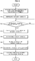
- FIG. 6 is a flowchart showing a method of controlling a driver assistance system according to an embodiment.
- connection or its derivatives refer both to direct and indirect connection, and the indirect connection includes a connection over a wireless communication network.
- the member when it is stated that one member is “on” another member, the member may be directly on the other member or a third member may be disposed therebetween.
- first,” “second,” “A,” “B,” etc. may be used to describe various components, the terms do not limit the corresponding components, but are used only for the purpose of distinguishing one component from another component.
- FIG. 1 is a block diagram illustrating a configuration of a vehicle according to an embodiment.
- a vehicle 1 includes an engine 10 , a transmission 20 , a braking device 30 , and a steering device 40 .
- the engine 10 may include a cylinder and a piston, and generate power required for the vehicle 1 to travel.
- the transmission 20 may include a plurality of gears, and transmit the power generated by the engine 10 to wheels.
- the braking device 30 may decelerate or stop the vehicle 1 through friction with the wheels.
- the steering device 40 may change the heading direction of the vehicle 1 .
- the vehicle 1 may include a plurality of machine parts.
- the vehicle 1 may include an engine management system (EMS) 11 , a transmission control unit (TCU) 21 , an electronic brake control module (EBCM) 31 , an electronic power steering (EPS) 41 , a body control module (BCM) 51 , and a driver assistance system (DAS) 100 .
- EMS engine management system
- TCU transmission control unit
- EBCM electronic brake control module
- EPS electronic power steering
- BCM body control module
- DAS driver assistance system
- the EMS 11 may control the engine 10 in response to an acceleration intention of the driver through an accelerator pedal or a request from the DAS 100 .
- the EMS 11 may control the torque of the engine 10 .
- the TCU 21 may control the transmission 20 in response to a shift command of the driver through a shift lever and/or a travelling speed of the vehicle 1 .
- the TCU 21 may adjust the gear ratio of the engine 10 to the wheels.
- the EBCM 31 may control the braking device 30 in response to a braking intention of the driver through a braking pedal and/or a slip of the wheels. For example, the EBCM 31 may temporarily release the braking of the wheels in response to a slip of the wheels sensed at a time of braking the vehicle 1 (anti-lock braking systems: ABS). The EBCM 31 may selectively release braking of the wheels in response to over-steering and/or under-steering sensed at a time of steering the vehicle 1 (electronic stability control: ESC). In addition, the EBCM 31 may temporarily brake the wheels in response to a slip of the wheels sensed at a time of driving the vehicle 1 (traction control system: TCS).
- the EPS 41 may assist the operation of the steering device 40 in response to a steering intention of the driver through the steering wheel such that the driver may easily operate the steering wheel.
- the EPS 41 may assist the operation of the steering device 40 such that the steering force is reduced during low-speed travelling or parking and the steering force is increased during high-speed travelling.
- the BCM 51 may control the operation of machine parts that provide convenience to the driver or ensure the safety of the driver.
- the BCM 51 may control a head lamp, a wiper, a cluster, a multifunction switch, a direction indicator lamp, and the like.
- the DAS 100 may assist the driver in manipulating (driving, braking, and steering) the vehicle 1 .
- the DAS 100 may sense a surrounding environment of the vehicle 1 (e.g., another vehicle, a pedestrian, a cyclist, a lane, a road sign, and the like), and control driving and/or braking and/or steering of the vehicle 1 in response to the sensed environment.
- a surrounding environment of the vehicle 1 e.g., another vehicle, a pedestrian, a cyclist, a lane, a road sign, and the like
- the DAS 100 may provide the driver with various functions.
- the DAS 100 may include a lane departure warning (LDW), a lane keeping assist (LKA), a high beam assist (HBA), an automatic emergency braking (AEB), a traffic sign recognition (TSR), a smart cruise control (SCC), a blind spot detection (BSD), and the like.
- LDW lane departure warning
- LKA lane keeping assist
- HBA high beam assist
- AEB automatic emergency braking
- TSR traffic sign recognition
- SCC smart cruise control
- BSD blind spot detection
- the DAS 100 includes a camera module 101 that acquires image data of the surrounding of the vehicle 1 and a radar module 102 that acquires object data of the surrounding of the vehicle 1 .
- the camera module 101 may include a camera 101 a and an electronic control unit (ECU) 101 b , and photograph at least one of the front or the lateral side of the vehicle 1 and recognize another vehicle, a pedestrian, a cyclist, a lane, a road sign, and the like.
- the camera 101 may be an image acquisition device comprising, but not limited to, a charge-coupled device (CCD), a CMOS image sensor, or a photo sensor including photodiodes.
- the radar module 102 may include a radar 102 a and an ECU 102 b , and acquire a relative position, a relative velocity, and the like of an object of the surrounding of the vehicle 1 (e.g., another vehicle, a pedestrian, a cyclists, and the like).
- an object of the surrounding of the vehicle 1 e.g., another vehicle, a pedestrian, a cyclists, and the like.
- the above described electronic components may communicate with each other through vehicle communication network NT.
- the machine parts may transmit data through Ethernet, media oriented systems transport (MOST), Flexray, controller area network (CAN), local interconnect network (LIN), and the like.
- the DAS 100 may transmit a driving control signal, a braking signal, and a steering signal to the EMS 11 , the EBCM 31 , and the EPS 41 , respectively.
- FIG. 2 is a block diagram illustrating a configuration of a DAS according to an embodiment.
- FIG. 3 is a view illustrating a camera and a radar included in a DAS according to an embodiment.
- the vehicle 1 may include a braking system 32 , a steering system 42 , and a DAS 100 .
- the braking system 32 includes the EBCM ( 31 in FIG. 1 ) and the braking device ( 30 in FIG. 1 ), which have been described with reference to FIG. 1
- the steering system 42 includes the EPS ( 41 in FIG. 1 ) and the steering device ( 40 in FIG. 1 ).
- the DAS 100 may include a front camera 110 , a front radar 120 , and a plurality of corner radars 130 .
- the front camera 110 may photograph the front of the vehicle 1 and acquire image data of the front of the vehicle 1 .
- the image data of the front of the vehicle 1 may include position information of another vehicle, a pedestrian, a cyclist, or a lane existing in front of the vehicle 1 .
- the front camera 110 may have fields of view 110 a and 110 b directed toward lateral sides of the vehicle 1 as well as the front of the vehicle 1 , as shown in FIG. 3 .
- the front camera 110 may acquire external image data of the surrounding of the vehicle 1 , the external image data including visual information regarding not only the front of the vehicle but also the lateral side of the vehicle 1 .
- the external image data of the vehicle 1 may include positional information of another vehicle, a pedestrian, a cyclist, or a lane positioned in at least one of the front or the lateral side of the vehicle 1 .
- the front camera 110 may include a plurality of lenses and an image sensor.
- the image sensor may include a plurality of photodiodes for converting light into electrical signals, and the plurality of photodiodes may be arranged in a two-dimensional matrix.
- the front camera 110 may be electrically connected to the controller 140 .
- the front camera 110 may be connected to the controller 140 through a vehicle communication network NT, may be connected to the controller 140 through a hard wire, or may be connected to the controller 140 through a printed circuit board (PCB).
- PCB printed circuit board
- the front camera 110 may transmit the external image data of the surrounding of the vehicle 1 including at least one of the front or the lateral side of the vehicle 1 to the controller 140 .
- the front camera 110 may be installed at a position capable of obtaining a field of view of the front or the lateral side of the vehicle 1 , for example, the front camera 110 may be installed on a front windshield of the vehicle 1 .
- the front radar 120 may include a transmission antenna (or a transmission antenna array) that radiates transmission radio waves forward of the vehicle 1 and a reception antenna (or a reception antenna array) that receives reflected radio waves reflected from an object.
- the front radar 120 may acquire front radar data from the transmission radio waves transmitted by the transmission antenna and the reflected radio waves received by the reception antenna.
- Front radar data may include distance information and velocity information regarding another vehicle, a pedestrian, or a cyclist existing in front of the vehicle 1 .
- the front radar 120 may calculate the relative distance to the object on the basis of the phase difference (or time difference) between the transmission radio waves and the reflected radio waves, and calculate the relative velocity of the object on the basis of the frequency difference between the transmission radio waves and the reflected radio waves.
- the front radar 120 may be connected to the controller 140 through a vehicle communication network NT, a hard wire, or a printed circuit board.
- the front radar 120 may transmit the front radar data to the controller 140 .
- the front radar 120 may be installed at a position capable of acquiring information regarding the front of the vehicle 1 , for example, the front radar 120 may be installed on a grille or a bumper of the vehicle 1 .
- the plurality of corner radars 130 includes a first corner radar 131 installed on the front right side of the vehicle 1 , a second corner radar 132 installed on the front left side of the vehicle 1 , a third corner radar 133 installed on the rear right side of the vehicle 1 , and a fourth corner radar 134 installed on the rear left side of the vehicle 1 .
- the first corner radar 131 may have a field of sensing 131 a directed toward the front right side of the vehicle 1 as shown in FIG. 3 .
- the first corner radar 131 may be installed on the right side of the front bumper of the vehicle 1 , for example.
- the second corner radar 132 may have a field of sensing 132 a directed toward the front left side of the vehicle 1 , and may be installed on the left side of the front bumper of the vehicle 1 , for example.
- the third corner radar 133 may have a field of sensing 133 a directed toward the rear right side of the vehicle 1 and may be installed on the right side of the rear bumper of the vehicle 1 , for example.
- the fourth corner radar 134 may have a field of sensing 134 a directed toward the rear left side of the vehicle 1 and may be installed on the left side of the rear bumper of the vehicle 1 , for example.
- Each of the first, second, third and fourth corner radars 131 , 132 , 133 , and 134 may include a transmission antenna and a reception antenna.
- the first, second, third, and fourth corner radars 131 , 132 , 133 and 134 acquire first corner radar data, second corner radar data, third corner radar data, and fourth corner radar data, respectively.
- the first corner radar data may include distance information and velocity information regarding another vehicle, a pedestrian, or a cyclist (hereinafter referred to as “an object”) positioned on the front right side of the vehicle 1 .
- the second corner radar data may include distance information and velocity information regarding an object positioned on the front left side of the vehicle 1 .
- the third and fourth corner radar data may respectively include distance and velocity information regarding an object located on the rear right side of the vehicle 1 and distance and velocity information regarding an object located on the rear left side of the vehicle 1 .
- Each of the first, second, third, and fourth corner radars 131 , 132 , 133 and 134 may be connected to the controller 140 through a vehicle communication network NT, a hard wire, or a printed circuit board, for example.
- the first, second, third, and fourth corner radars 131 , 132 , 133 , and 134 may respectively transmit the first corner radar data, the second corner radar data, the third corner radar data, and the fourth corner radar data to the controller 140 .
- the radar 102 a including the front radar 120 and the plurality of corner radars 130 described above may transmit the front radar data of the front radar 120 and the corner radar data of the plurality of corner radars 130 to the controller 140 .
- the controller 140 may include the ECU ( 101 b in FIG. 1 ) of the camera module ( 101 in FIG. 1 ) and/or the ECU ( 102 b in FIG. 1 ) of the radar module ( 102 in FIG. 1 ), and/or an integrated ECU.
- the controller 140 includes a processor 141 and a memory 142 .
- the processor 141 may process the external image data of the front camera 110 and the radar data of the radar 102 a , and generate a braking signal and a steering signal for controlling the braking system 32 and the steering system 42 .
- the processor 141 may include an image signal processor for processing external image data of the front camera 110 and/or a digital signal processor for processing radar data of the radar 102 a and/or a micro control unit (MCU) for generating a braking signal and a steering signal.
- MCU micro control unit
- the processor 141 may determine objects (e.g., another vehicle, a pedestrian, a cyclist, and the like) front or lateral side of the vehicle 1 by processing the external image data of the front camera 110 and the radar data of the radar 102 a.
- objects e.g., another vehicle, a pedestrian, a cyclist, and the like
- the processor 141 may acquire position information (distance and direction) and velocity information (relative velocity) of the object in front of or behind the vehicle 1 on the basis of the radar data of the radar 102 a .
- the processor 141 may acquire position information (direction) and type information (for example, whether the object is another vehicle, a pedestrian, or a cyclist) of the object in front of or behind the vehicle 1 on the basis of the external image data of the front camera 110 .
- the processor 141 allows the object sensed by the external image data to match the object sensed by the radar data, and acquires the type information, the position information, and the velocity information of the surrounding objects of the vehicle 1 on the basis of a result of the matching.
- the processor 141 may generate a braking signal and a steering signal on the basis of the type information, the position information, and the velocity information of the surrounding objects.
- the processor 141 calculates a time to collision (TTC) between the vehicle 1 and the surrounding object on the basis of the position information (distance) and the velocity information (relative velocity) of the surrounding object, and warns the driver of a collision or transmits a braking signal to the braking system 32 on the basis of a result of comparing the TTC with a predetermined reference time.
- TTC time to collision
- the processor 141 may allow an alert to be output via audio and/or display.
- the processor 141 may transmit a preliminary-braking signal to the braking system 32 .
- the processor 141 may transmit an emergency braking signal to the braking system 32 .
- the second reference time is shorter than the first reference time
- the third reference time is shorter than the second reference time.
- the processor 141 may calculate a distance to collision (DTC) on the basis of the velocity information (relative speed) of surrounding objects, and warn the driver of a collision or transmit a braking signal to the braking system 32 on the basis of a result of comparing the DTC with distances to the surrounding objects.
- DTC distance to collision
- the processor 141 may acquire position information (distance and direction) and velocity information (relative velocity) of the objects on the sides of the vehicle 1 (front right, front left, rear right, and rear left) on the basis of corner radar data of the plurality of corner radars 130 .
- the controller 140 may transmit a control signal to the braking system 32 or the steering system 42 on the basis of whether a collision with the front or side object is predicted to occur.
- the controller 140 transmits a braking signal to the braking system 32 to avoid a collision with the side object, to perform a longitudinal avoidance.
- the controller 140 transmits a steering signal to the steering system 42 to avoid a collision with the side object, to perform a lateral avoidance.
- the controller 140 may transmit a steering signal to the steering system 42 to avoid a collision with a front object.
- the controller 140 may not transmit the steering signal to the steering system 42 .
- the memory 142 stores programs and/or data for processing image data by the processor 141 , programs and/or data for processing radar data by the processor 141 , and programs and/or data for generating a braking signal and/or a steering signal by the processor 141 .
- the memory 142 may temporarily store the image data received from the front camera 110 and/or the radar data received from the radars 120 and 130 , and may temporarily store a result of processing the image data and/or the radar data of the processor 141 .
- the memory 142 may include a volatile memory, such as an S-RAM, a D-RAM, and the like, and a non-volatile memory, such as a flash memory, a read only memory (ROM), an erasable programmable read only memory (EPROM), and the like.
- the programs stored in the memory 142 when executed by the processor 141 , causes the processor 141 (or the controller 140 including the processor 141 ) to perform the operations/functions described in the specification.
- At least one of the components may be omitted or add to correspond to the performances of the components of the vehicle 1 shown in FIGS. 1 and 2 .
- the positions of the components may be changed to correspond to the performance and structure of the system without being limited.
- FIGS. 1 and 2 refer to software components and/or hardware components, such as a field programmable gate array (FPGA) and an application specific integrated circuit (ASIC).
- FPGA field programmable gate array
- ASIC application specific integrated circuit
- FIG. 4 is a view illustrating a camera and a radar included in a conventional driver assistance system.
- a front camera 110 ′ included in the conventional driver assistance system may have a field of view 110 a ′ directed toward the front of a vehicle 1 ′.
- a front radar 120 ′ may have a field of sensing 120 a ′ directed toward to the front of the vehicle 1 ′ as shown in FIG. 4 .
- the angle of the field of view 110 a ′ of the front camera 110 ′ or the field of sensing 120 a ′ of the first radar 120 ′ is limited with respect to the front of the vehicle 1 ′. Accordingly, it is difficult to acquire information about a surrounding object located outside the limited angle of field of view 110 a ′ or field of sensing 120 a′.
- the vehicle cut in at a close range may not be sensed due to the limited angle of field of view 110 a ′ or field of sensing 120 a ′. Accordingly, it is important to prevent collision with surrounding objects located outside the limited angle of field of view 110 a ′ or field of sensing 120 a′.
- driver assistance system 100 capable of preventing a collision occurring due to the limited angle of field of view 110 a ′ or field of sensing 120 a ′ of the conventional driver assistance system and more rapidly detecting a vehicle cut in at a close range.
- FIG. 5 is a view for describing an operation for avoiding a collision with a vehicle that cuts in a travel lane of a vehicle implemented with a driver assistance system according to an embodiment.
- the controller 140 may determine a nearby vehicle on the basis of the external image data acquired by the front camera 110 .
- the nearby vehicle represents a vehicle existing in a lane of at least one of a left side or a right side of the travel lane of the vehicle 1 .
- the controller 140 may acquire lane information regarding a travel lane of the vehicle 1 and sensing information regarding a nearby vehicle on the basis of the external image data acquired by the front camera 110 .
- the lane information represents information regarding a travel lane of the vehicle 1 , and may include at least one of the position, coordinates, trajectory, width, angle, and interval of the travel lane.
- the lane information according to the present disclosure is not limited thereto, and may include various pieces of information regarding the travel lane of the vehicle 1 .
- the sensing information represents information regarding a vehicle existing at a surrounding of the vehicle 1 , and may include at least one of vertex coordinates, longitudinal minimum coordinates, lateral minimum coordinates, longitudinal maximum coordinates, lateral maximum coordinates, a width, a length, and a heading angle of a nearby vehicle.
- the vertex coordinates of the nearby vehicle represents a point where edges of the nearby vehicle meet.
- the sensing information may include various pieces of other information regarding the nearby vehicle at a surrounding of the vehicle 1 .
- the controller 140 may determine whether the nearby vehicle makes a contact with the travel lane on the basis of the external image data, and when the nearby vehicle makes a contact with the travel lane, the coordinates of a contact point of the travel lane and the nearby vehicle may be acquired.
- the sensing information may further include the coordinates of the contact point of the travel lane of the vehicle 1 and the nearby vehicle.
- the controller 140 may determine whether the nearby vehicle is predicted to cut in the travel lane on the basis of the external image data.
- the controller 140 may calculate a lateral acceleration of the nearby vehicle on the basis of the external image data, and determine whether the nearby vehicle is predicted to cut in on the travel lane on the basis of whether the calculated lateral acceleration satisfies a predetermined first condition.
- the sensing information may further include the lateral acceleration of the nearby vehicle.
- the controller 140 may determine whether the nearby vehicle is predicted to cut in the travel lane on the basis of whether the heading angle of the nearby vehicle acquired on the basis of the external image data satisfies a predetermined second condition.
- controller 140 may calculate a cut-in area S of the nearby vehicle on the basis of the external image data.
- the controller 140 may calculate the cut-in area of the nearby vehicle on the basis of the lane information and the sensing information regarding the nearby vehicle that are acquired on the basis of the external image data.
- the controller 140 may calculate the cut-in area of the nearby vehicle using the coordinates of the point where the nearby vehicle makes a contact with the travel lane, that is, the contact point of the nearby vehicle and the travel lane on the basis of the lane information and the sensing information.
- the controller 140 may calculate the cut-in area of the nearby vehicle on the basis of the coordinates of the contact point of the nearby vehicle and the travel lane and the vertex coordinates of the nearby vehicle.
- the vertex coordinates of the nearby vehicle may represent the coordinates of a vertex at the maximum distance from the travel lane among vertices located within the travel lane.
- the vertex coordinates of the vertex of the nearby vehicle may be the coordinates of a vertex having the longitudinal maximum coordinates from the travel lane.
- the controller 140 may calculate the cut-in area of the nearby vehicle on the basis of the coordinates of the contact point of the nearby vehicle and the travel lane, the vertex coordinates of the nearby vehicle, and the heading angle of the nearby vehicle.
- the operations/functions of the controller 140 may be performed by the processor 141 when the processor 141 executes software, program, or codes stored in the memory 142 .
- the controller 140 may calculate a cut-in area S of the nearby vehicle 3 on the basis of coordinates of contact points X 5 and X 6 of the nearby vehicle 3 and the travel lane L 1 , and coordinates of vertexes X 1 , X 2 , X 3 , and X 4 of the nearby vehicle 3 .
- the controller 140 may calculate the cut-in area S of the nearby vehicle 3 on the basis of the heading angle of the nearby vehicle 3 , the coordinates of the contact points X 5 and X 6 of the nearby vehicle 3 and the travel lane L 1 , and the coordinates of the vertex X 1 located within the travel lane L 1 and having the longitudinal maximum coordinates from the travel lane L 1 .
- the controller 140 may calculate the distances Sa, Sb, and Sc between vertexes of a polygon forming the cut-in area S, to calculate the cut-in area S.
- the controller 140 may determine a target vehicle 2 on the basis of the cut-in area of the nearby vehicle, and may control at least one of the braking system 32 or the steering system 42 to avoid a collision with the target vehicle 2 .
- the target vehicle 2 represents a vehicle for which a collision is avoided.
- the controller 140 may determine the target vehicle 2 on the basis of whether the cut-in area of the nearby vehicle 3 is equal to or larger than a predetermined reference value, and calculate a target acceleration on the basis of the velocity of the target vehicle 2 . To this end, the controller 140 may calculate the velocity (relative velocity) of the target vehicle 2 on the basis of at least one of the radar data acquired by the radar 102 a or the external image data acquired by the front camera 110 .
- the controller 140 may calculate the target acceleration on the basis of the velocity of the target vehicle 2 .
- the target acceleration represents an acceleration required to avoid a collision with the target vehicle 2 , and an acceleration required to perform a longitudinal avoidance on the target vehicle 2 .
- the controller 140 may output a braking signal for the longitudinal avoidance to the braking system 32 on the basis of the target acceleration.
- the controller 140 When the collision with the target vehicle 2 is predicted to occur or the longitudinal avoidance is impossible even after the braking signal for the longitudinal avoidance is transmitted, the controller 140 outputs a steering signal for a lateral avoidance to the steering system 42 .
- the controller 140 may calculate cut-in areas of the plurality of nearby vehicles, and may determine a nearby vehicle having the largest cut-in area as the target vehicle among the plurality of nearby vehicles. In the following description, details identical to those described above will be omitted.
- FIG. 6 is a flowchart showing a method of controlling a driver assistance system according to an embodiment.
- the driver assistance system 100 may acquire sensing information and lane information from the front camera 110 ( 311 ).
- the driver assistance system 100 may acquire the sensing information and the lane information on the basis of the external image data acquired from the front camera 110 .
- the lane information represents information regarding a travel lane of the vehicle 1 , and may include at least one of the position, coordinates, trajectory, width, angle, or interval of the travel lane.
- the lane information according to the present disclosure is not limited thereto, and may include various pieces of information regarding the travel lane of the vehicle 1 .
- the sensing information represents information regarding a vehicle existing at a surrounding of the vehicle 1 , and may include at least one of vertex coordinates, longitudinal minimum coordinates, lateral minimum coordinates, longitudinal maximum coordinates, lateral maximum coordinates, a width, a length, or a heading angle, of a nearby vehicle.
- the vertex coordinates of the nearby vehicle represents a point where edges of the nearby vehicle meet.
- the sensing information may include various pieces of other information regarding the nearby vehicle at a surrounding of the vehicle 1 , and may further include the coordinates of a contact point of the travel lane and the nearby vehicle or the lateral acceleration of the nearby vehicle.
- the driver assistance system 1 may determine a nearby vehicle on the basis of the lane information and the sensing information ( 312 ).
- the nearby vehicle represents a vehicle in a lane of at least one of a left side or a right side of the travel lane of the vehicle 1 .
- the driver assistance system 1 may determine whether the nearby vehicle is predicted to cut in the travel lane on the basis of the lane information and the sensing information ( 313 ). In detail, the driver assistance system 1 may determine whether the nearby vehicle is predicted to cut in the travel lane on the basis of whether a lateral acceleration of the nearby vehicle satisfies a predetermined first condition. Alternatively, the driver assistance system 100 may determine whether the nearby vehicle is predicted to cut in the travel lane on the basis of whether a heading angle of the nearby vehicle satisfies a predetermined second condition.
- the driver assistance system 100 may calculate a cut-in area of the nearby vehicle ( 314 ).
- the driver assistance system 1 may calculate the cut-in area of the nearby vehicle on the basis of the lane information and the sensing information regarding the nearby vehicle that are acquired on the basis of the external image data.
- the driver assistance system 1 may calculate the cut-in area of the nearby vehicle using the coordinates of the point where the nearby vehicle makes a contact with the travel lane, that is, the contact point of the nearby vehicle and the travel lane on the basis of the lane information and the sensing information.
- the driver assistance system 100 may calculate the cut-in area of the nearby vehicles on the basis of the coordinates of the contact point of the nearby vehicle and the travel lane and the vertex coordinates of the nearby vehicle.
- the vertex coordinates of the nearby vehicle may represent the coordinates of a vertex at the maximum distance from the travel lane among vertices located within the travel lane.
- the vertex coordinates of the nearby vehicle may be the coordinates of a vertex having the longitudinal maximum coordinates from the travel lane.
- the driver assistance system 100 may calculate the cut-in area of the nearby vehicle not only based on the coordinates of the contact point of the nearby vehicle and the travel lane and the vertex coordinates of the nearby vehicle but also based on the heading angle of the nearby vehicle.
- the driver assistance system 1 may determine a target vehicle on the basis of the cut-in area of the nearby vehicle ( 315 ).
- the target vehicle represents a vehicle for which a collision is avoided.
- the driver assistance system 100 may determine the target vehicle on the basis of whether the cut-in area of the nearby vehicle is equal to or larger than a predetermined reference value. In this case, when there are a plurality of nearby vehicles, the driver assistance system 1 may calculate cut-in areas of the plurality of nearby vehicles, and may determine a nearby vehicle having the largest cut-in area as the target vehicle among the plurality of nearby vehicles.
- the driver assistance system 100 may sense the velocity of the target vehicle ( 316 ), and may determine the target acceleration on the basis of the velocity of the target vehicle ( 317 ).
- the target acceleration may represent an acceleration required to avoid a collision with the target vehicle, and may represent an acceleration required to perform a longitudinal avoidance on the target vehicle.
- the driver assistance system 1 may control at least one of the braking system 32 or the steering system 42 on the basis of the target acceleration ( 318 ).
- the driver assistance system 100 may output a braking signal for the longitudinal avoidance to the braking system 32 on the basis of the target acceleration.
- the driver assistance system 1 may output a steering signal for a lateral avoidance to the steering system 42 .
- a vehicle cut in the travel lane at a close range may be more rapidly sensed, so that an operation of avoiding a collision may be performed, and the driver may be provided with safer travelling environment.
- the disclosed embodiments may be embodied in the form of a recording medium storing instructions executable by a computer.
- the instructions may be stored in the form of program code and, when executed by a processor, may generate a program module to perform the operations of the disclosed embodiments.
- the recording medium may be embodied as a computer-readable recording medium.
- the computer-readable recording medium includes all kinds of recording media in which instructions which can be decoded by a computer are stored, for example, a Read Only Memory (ROM), a Random Access Memory (RAM), a magnetic tape, a magnetic disk, a flash memory, an optical data storage device, and the like.
- ROM Read Only Memory
- RAM Random Access Memory
- magnetic tape a magnetic tape
- magnetic disk a magnetic disk
- flash memory an optical data storage device
- the driver assistance system and the control method thereof can avoid a collision between a vehicle and a surrounding object, thus providing a driver with a safe travelling environment.
Landscapes
- Engineering & Computer Science (AREA)
- Mechanical Engineering (AREA)
- Transportation (AREA)
- Radar, Positioning & Navigation (AREA)
- Remote Sensing (AREA)
- Physics & Mathematics (AREA)
- Automation & Control Theory (AREA)
- General Physics & Mathematics (AREA)
- Chemical & Material Sciences (AREA)
- Combustion & Propulsion (AREA)
- Computer Networks & Wireless Communication (AREA)
- Aviation & Aerospace Engineering (AREA)
- Mathematical Physics (AREA)
- Electromagnetism (AREA)
- Human Computer Interaction (AREA)
- Computer Vision & Pattern Recognition (AREA)
- Multimedia (AREA)
- Traffic Control Systems (AREA)
Abstract
Description
Claims (30)
Applications Claiming Priority (2)
| Application Number | Priority Date | Filing Date | Title |
|---|---|---|---|
| KR1020190011785A KR102673147B1 (en) | 2019-01-30 | 2019-01-30 | Driver assistance system and controlling method thereof |
| KR10-2019-0011785 | 2019-01-30 |
Publications (2)
| Publication Number | Publication Date |
|---|---|
| US20200238982A1 US20200238982A1 (en) | 2020-07-30 |
| US11299147B2 true US11299147B2 (en) | 2022-04-12 |
Family
ID=69024173
Family Applications (1)
| Application Number | Title | Priority Date | Filing Date |
|---|---|---|---|
| US16/715,671 Active US11299147B2 (en) | 2019-01-30 | 2019-12-16 | Driver assistance system and control method thereof |
Country Status (4)
| Country | Link |
|---|---|
| US (1) | US11299147B2 (en) |
| EP (1) | EP3690481B1 (en) |
| KR (1) | KR102673147B1 (en) |
| CN (1) | CN111497833B (en) |
Cited By (2)
| Publication number | Priority date | Publication date | Assignee | Title |
|---|---|---|---|---|
| US20230048316A1 (en) * | 2021-08-03 | 2023-02-16 | Gm Cruise Holdings Llc | Radar system that uses velocity labeled multiplexing for generating detections |
| US12146949B2 (en) | 2021-08-03 | 2024-11-19 | Gm Cruise Holdings Llc | Phase modulated continuous wave radar system that uses velocity labeled multiplexing for generating detections |
Families Citing this family (16)
| Publication number | Priority date | Publication date | Assignee | Title |
|---|---|---|---|---|
| US10460534B1 (en) * | 2015-10-26 | 2019-10-29 | Allstate Insurance Company | Vehicle-to-vehicle accident detection |
| US10303166B2 (en) * | 2016-05-23 | 2019-05-28 | nuTonomy Inc. | Supervisory control of vehicles |
| JP7261635B2 (en) * | 2019-03-28 | 2023-04-20 | 本田技研工業株式会社 | vehicle controller |
| KR102899259B1 (en) * | 2020-03-11 | 2025-12-12 | 주식회사 에이치엘클레무브 | Vehicle and method of controlling the same |
| CN111950504B (en) * | 2020-08-21 | 2024-04-16 | 东软睿驰汽车技术(沈阳)有限公司 | Vehicle detection method and device and electronic equipment |
| CN112248986B (en) * | 2020-10-23 | 2021-11-05 | 厦门理工学院 | Automatic braking method, device, equipment and storage medium for vehicle |
| KR20220056922A (en) * | 2020-10-28 | 2022-05-09 | 현대자동차주식회사 | Apparatus and method for controlling autonomous driving of vehicle |
| CN112428989B (en) * | 2020-10-30 | 2022-03-11 | 惠州华阳通用电子有限公司 | Vehicle control method |
| CN112863195B (en) * | 2021-03-18 | 2022-06-14 | 浙江大华技术股份有限公司 | Vehicle state determination method and device |
| KR102672340B1 (en) * | 2021-04-20 | 2024-06-07 | 주식회사 에이치엘클레무브 | Apparatus for assisting driving and method thereof |
| JP7716510B2 (en) * | 2022-02-08 | 2025-07-31 | 株式会社デンソー | Periphery monitoring device and program |
| CN115158306B (en) * | 2022-07-27 | 2024-06-04 | 广州小鹏自动驾驶科技有限公司 | Vehicle avoidance method, device, terminal equipment and storage medium |
| CN117799604B (en) * | 2022-09-30 | 2026-01-06 | 比亚迪股份有限公司 | A vehicle control method, apparatus, equipment, vehicle, and medium |
| CN116513177A (en) * | 2023-04-23 | 2023-08-01 | 上汽通用五菱汽车股份有限公司 | Adaptive cruise control method and system based on cut-in of front vehicle |
| CN116653979B (en) * | 2023-05-31 | 2024-01-05 | 钧捷智能(深圳)有限公司 | Driver visual field range ray tracing method and DMS system |
| CN118651237B (en) * | 2024-08-19 | 2024-12-10 | 比亚迪股份有限公司 | Lane change detection method, electronic device, vehicle and storage medium |
Citations (10)
| Publication number | Priority date | Publication date | Assignee | Title |
|---|---|---|---|---|
| US20020027503A1 (en) | 2000-09-04 | 2002-03-07 | Takashi Higuchi | Periphery monitoring system |
| US6744380B2 (en) * | 2001-10-10 | 2004-06-01 | Denso Corporation | Apparatus for monitoring area adjacent to vehicle |
| US6894608B1 (en) * | 1999-07-22 | 2005-05-17 | Altra Technologies Incorporated | System and method for warning of potential collisions |
| US20070150196A1 (en) * | 2005-12-09 | 2007-06-28 | Grimm Donald K | Method for detecting or predicting vehicle cut-ins |
| US20140324330A1 (en) * | 2013-04-26 | 2014-10-30 | Denso Corporation | Collision determination device and collision mitigation device |
| EP3141926A1 (en) | 2015-09-10 | 2017-03-15 | Continental Automotive GmbH | Automated detection of hazardous drifting vehicles by vehicle sensors |
| WO2018074287A1 (en) | 2016-10-18 | 2018-04-26 | 株式会社デンソー | Vehicle control device |
| US20180141545A1 (en) | 2016-11-21 | 2018-05-24 | NextEv USA, Inc. | Systems and methods for automatically disengaging a braking function of a vehicle |
| US10460182B1 (en) * | 2018-10-25 | 2019-10-29 | Mando Corporation | Driver assistance system and control method thereof |
| US20200082248A1 (en) * | 2018-09-11 | 2020-03-12 | Nvidia Corporation | Future object trajectory predictions for autonomous machine applications |
Family Cites Families (7)
| Publication number | Priority date | Publication date | Assignee | Title |
|---|---|---|---|---|
| JPH06265348A (en) * | 1993-03-12 | 1994-09-20 | Mitsubishi Electric Corp | Inter-vehicle distance detector |
| JP3868915B2 (en) * | 2003-03-12 | 2007-01-17 | 株式会社東芝 | Forward monitoring apparatus and method |
| JP5042496B2 (en) * | 2005-12-27 | 2012-10-03 | 富士重工業株式会社 | Driving assistance device |
| JP2008117073A (en) * | 2006-11-01 | 2008-05-22 | Fuji Heavy Ind Ltd | Interrupting vehicle detection device |
| KR101293108B1 (en) * | 2009-05-29 | 2013-08-12 | 주식회사 만도 | Control method of vehicle |
| CN103832433B (en) * | 2012-11-21 | 2016-08-10 | 中国科学院沈阳计算技术研究所有限公司 | Deviation and front truck anti-collision alarm system and its implementation |
| KR101519287B1 (en) * | 2014-02-14 | 2015-05-11 | 현대자동차주식회사 | Apparatus and method for preventing vehicle collision |
-
2019
- 2019-01-30 KR KR1020190011785A patent/KR102673147B1/en active Active
- 2019-12-02 CN CN201911213041.8A patent/CN111497833B/en active Active
- 2019-12-16 US US16/715,671 patent/US11299147B2/en active Active
- 2019-12-24 EP EP19219610.3A patent/EP3690481B1/en active Active
Patent Citations (14)
| Publication number | Priority date | Publication date | Assignee | Title |
|---|---|---|---|---|
| US6894608B1 (en) * | 1999-07-22 | 2005-05-17 | Altra Technologies Incorporated | System and method for warning of potential collisions |
| US20020027503A1 (en) | 2000-09-04 | 2002-03-07 | Takashi Higuchi | Periphery monitoring system |
| US6636148B2 (en) * | 2000-09-04 | 2003-10-21 | Fujitsu Ten Limited | Periphery monitoring system |
| US6744380B2 (en) * | 2001-10-10 | 2004-06-01 | Denso Corporation | Apparatus for monitoring area adjacent to vehicle |
| US20070150196A1 (en) * | 2005-12-09 | 2007-06-28 | Grimm Donald K | Method for detecting or predicting vehicle cut-ins |
| US7444241B2 (en) | 2005-12-09 | 2008-10-28 | Gm Global Technology Operations, Inc. | Method for detecting or predicting vehicle cut-ins |
| US20140324330A1 (en) * | 2013-04-26 | 2014-10-30 | Denso Corporation | Collision determination device and collision mitigation device |
| US9460627B2 (en) * | 2013-04-26 | 2016-10-04 | Denso Corporation | Collision determination device and collision mitigation device |
| EP3141926A1 (en) | 2015-09-10 | 2017-03-15 | Continental Automotive GmbH | Automated detection of hazardous drifting vehicles by vehicle sensors |
| WO2018074287A1 (en) | 2016-10-18 | 2018-04-26 | 株式会社デンソー | Vehicle control device |
| US20190263344A1 (en) * | 2016-10-18 | 2019-08-29 | Denso Corporation | Vehicle control device |
| US20180141545A1 (en) | 2016-11-21 | 2018-05-24 | NextEv USA, Inc. | Systems and methods for automatically disengaging a braking function of a vehicle |
| US20200082248A1 (en) * | 2018-09-11 | 2020-03-12 | Nvidia Corporation | Future object trajectory predictions for autonomous machine applications |
| US10460182B1 (en) * | 2018-10-25 | 2019-10-29 | Mando Corporation | Driver assistance system and control method thereof |
Non-Patent Citations (1)
| Title |
|---|
| Extended European Search Report issued in European Patent Application No. 19219610.3 dated Jun. 22, 2020. |
Cited By (5)
| Publication number | Priority date | Publication date | Assignee | Title |
|---|---|---|---|---|
| US20230048316A1 (en) * | 2021-08-03 | 2023-02-16 | Gm Cruise Holdings Llc | Radar system that uses velocity labeled multiplexing for generating detections |
| US12019151B2 (en) | 2021-08-03 | 2024-06-25 | Gm Cruise Holdings Llc | Radar system that uses velocity labeled multiplexing for generating detections |
| US12038503B2 (en) * | 2021-08-03 | 2024-07-16 | Gm Cruise Holdings Llc | Radar system that uses velocity labeled multiplexing for generating detections |
| US12146949B2 (en) | 2021-08-03 | 2024-11-19 | Gm Cruise Holdings Llc | Phase modulated continuous wave radar system that uses velocity labeled multiplexing for generating detections |
| US12455371B2 (en) | 2021-08-03 | 2025-10-28 | Gm Cruise Holdings Llc | Radar system that uses velocity labeled multiplexing for generating detections |
Also Published As
| Publication number | Publication date |
|---|---|
| US20200238982A1 (en) | 2020-07-30 |
| CN111497833A (en) | 2020-08-07 |
| KR102673147B1 (en) | 2024-06-07 |
| KR20200094378A (en) | 2020-08-07 |
| EP3690481A1 (en) | 2020-08-05 |
| EP3690481B1 (en) | 2023-11-29 |
| CN111497833B (en) | 2024-08-02 |
Similar Documents
| Publication | Publication Date | Title |
|---|---|---|
| US11299147B2 (en) | Driver assistance system and control method thereof | |
| US11505183B2 (en) | Driver assistance system and method | |
| US11840220B2 (en) | Driver assistance system and control method thereof | |
| US11605299B2 (en) | Vehicle and control method thereof | |
| CN112061120A (en) | Advanced driver assistance system, vehicle having the same, and vehicle control method | |
| KR102877028B1 (en) | Driver assistance system and method therof | |
| US11634120B2 (en) | Driver assistance system and driver assistance method | |
| KR20210130297A (en) | Driver assistance apparatus | |
| CN115871655A (en) | Vehicle and control method thereof | |
| KR20210080720A (en) | Driver assistance apparatus and driver assisting method | |
| US12043310B2 (en) | Driver assistance system and control method for the same | |
| US12344236B2 (en) | Driver assistance apparatus and driver assisting method | |
| US11577730B2 (en) | Vehicle and control method thereof | |
| KR20210084713A (en) | Driver assistance system and driver assistance method | |
| KR102440265B1 (en) | driver assistance system | |
| KR102700168B1 (en) | Driver assistance apparatus | |
| US20230089888A1 (en) | Apparatus and method for assisting in driving vehicle | |
| KR20210088117A (en) | Driver assistance system and method therof | |
| US12497029B2 (en) | Vehicle and control method thereof | |
| KR102936876B1 (en) | Vehicle and control method thereof | |
| KR20200141795A (en) | driver assistance SYSTEM AND CONTROLLING METHOD THEREOF | |
| KR20220085084A (en) | driver assistance System and control method for the same |
Legal Events
| Date | Code | Title | Description |
|---|---|---|---|
| AS | Assignment |
Owner name: MANDO CORPORATION, KOREA, REPUBLIC OF Free format text: ASSIGNMENT OF ASSIGNORS INTEREST;ASSIGNOR:KANG, BORYEON;REEL/FRAME:051313/0115 Effective date: 20191023 |
|
| FEPP | Fee payment procedure |
Free format text: ENTITY STATUS SET TO UNDISCOUNTED (ORIGINAL EVENT CODE: BIG.); ENTITY STATUS OF PATENT OWNER: LARGE ENTITY |
|
| STPP | Information on status: patent application and granting procedure in general |
Free format text: DOCKETED NEW CASE - READY FOR EXAMINATION |
|
| STPP | Information on status: patent application and granting procedure in general |
Free format text: FINAL REJECTION MAILED |
|
| STPP | Information on status: patent application and granting procedure in general |
Free format text: RESPONSE AFTER FINAL ACTION FORWARDED TO EXAMINER |
|
| STPP | Information on status: patent application and granting procedure in general |
Free format text: ADVISORY ACTION MAILED |
|
| STPP | Information on status: patent application and granting procedure in general |
Free format text: DOCKETED NEW CASE - READY FOR EXAMINATION |
|
| STPP | Information on status: patent application and granting procedure in general |
Free format text: NON FINAL ACTION MAILED |
|
| STPP | Information on status: patent application and granting procedure in general |
Free format text: RESPONSE TO NON-FINAL OFFICE ACTION ENTERED AND FORWARDED TO EXAMINER |
|
| STPP | Information on status: patent application and granting procedure in general |
Free format text: FINAL REJECTION MAILED |
|
| AS | Assignment |
Owner name: MANDO MOBILITY SOLUTIONS CORPORATION, KOREA, REPUBLIC OF Free format text: ASSIGNMENT OF ASSIGNORS INTEREST;ASSIGNOR:MANDO CORPORATION;REEL/FRAME:058598/0480 Effective date: 20211026 |
|
| STPP | Information on status: patent application and granting procedure in general |
Free format text: ADVISORY ACTION COUNTED, NOT YET MAILED |
|
| STPP | Information on status: patent application and granting procedure in general |
Free format text: NOTICE OF ALLOWANCE MAILED -- APPLICATION RECEIVED IN OFFICE OF PUBLICATIONS |
|
| STPP | Information on status: patent application and granting procedure in general |
Free format text: PUBLICATIONS -- ISSUE FEE PAYMENT VERIFIED |
|
| STCF | Information on status: patent grant |
Free format text: PATENTED CASE |
|
| AS | Assignment |
Owner name: HL KLEMOVE CORP., KOREA, REPUBLIC OF Free format text: MERGER;ASSIGNOR:MANDO MOBILITY SOLUTIONS CORPORATION;REEL/FRAME:061148/0166 Effective date: 20211202 |
|
| MAFP | Maintenance fee payment |
Free format text: PAYMENT OF MAINTENANCE FEE, 4TH YEAR, LARGE ENTITY (ORIGINAL EVENT CODE: M1551); ENTITY STATUS OF PATENT OWNER: LARGE ENTITY Year of fee payment: 4 |