US11298586B1 - End platform for an exercise machine - Google Patents
End platform for an exercise machine Download PDFInfo
- Publication number
- US11298586B1 US11298586B1 US17/113,231 US202017113231A US11298586B1 US 11298586 B1 US11298586 B1 US 11298586B1 US 202017113231 A US202017113231 A US 202017113231A US 11298586 B1 US11298586 B1 US 11298586B1
- Authority
- US
- United States
- Prior art keywords
- platform
- end platform
- gripping surface
- transverse
- handle
- Prior art date
- Legal status (The legal status is an assumption and is not a legal conclusion. Google has not performed a legal analysis and makes no representation as to the accuracy of the status listed.)
- Active, expires
Links
Images


Classifications
-
- A—HUMAN NECESSITIES
- A63—SPORTS; GAMES; AMUSEMENTS
- A63B—APPARATUS FOR PHYSICAL TRAINING, GYMNASTICS, SWIMMING, CLIMBING, OR FENCING; BALL GAMES; TRAINING EQUIPMENT
- A63B22/00—Exercising apparatus specially adapted for conditioning the cardio-vascular system, for training agility or co-ordination of movements
- A63B22/0087—Exercising apparatus specially adapted for conditioning the cardio-vascular system, for training agility or co-ordination of movements with a seat or torso support moving during the exercise, e.g. reformers
- A63B22/0089—Exercising apparatus specially adapted for conditioning the cardio-vascular system, for training agility or co-ordination of movements with a seat or torso support moving during the exercise, e.g. reformers a counterforce being provided to the support
-
- A—HUMAN NECESSITIES
- A63—SPORTS; GAMES; AMUSEMENTS
- A63B—APPARATUS FOR PHYSICAL TRAINING, GYMNASTICS, SWIMMING, CLIMBING, OR FENCING; BALL GAMES; TRAINING EQUIPMENT
- A63B22/00—Exercising apparatus specially adapted for conditioning the cardio-vascular system, for training agility or co-ordination of movements
- A63B22/20—Exercising apparatus specially adapted for conditioning the cardio-vascular system, for training agility or co-ordination of movements using rollers, wheels, castors or the like, e.g. gliding means, to be moved over the floor or other surface, e.g. guide tracks, during exercising
- A63B22/201—Exercising apparatus specially adapted for conditioning the cardio-vascular system, for training agility or co-ordination of movements using rollers, wheels, castors or the like, e.g. gliding means, to be moved over the floor or other surface, e.g. guide tracks, during exercising for moving a support element in reciprocating translation, i.e. for sliding back and forth on a guide track
- A63B22/203—Exercising apparatus specially adapted for conditioning the cardio-vascular system, for training agility or co-ordination of movements using rollers, wheels, castors or the like, e.g. gliding means, to be moved over the floor or other surface, e.g. guide tracks, during exercising for moving a support element in reciprocating translation, i.e. for sliding back and forth on a guide track in a horizontal plane
-
- A—HUMAN NECESSITIES
- A63—SPORTS; GAMES; AMUSEMENTS
- A63B—APPARATUS FOR PHYSICAL TRAINING, GYMNASTICS, SWIMMING, CLIMBING, OR FENCING; BALL GAMES; TRAINING EQUIPMENT
- A63B21/00—Exercising apparatus for developing or strengthening the muscles or joints of the body by working against a counterforce, with or without measuring devices
- A63B21/00058—Mechanical means for varying the resistance
- A63B21/00065—Mechanical means for varying the resistance by increasing or reducing the number of resistance units
-
- A—HUMAN NECESSITIES
- A63—SPORTS; GAMES; AMUSEMENTS
- A63B—APPARATUS FOR PHYSICAL TRAINING, GYMNASTICS, SWIMMING, CLIMBING, OR FENCING; BALL GAMES; TRAINING EQUIPMENT
- A63B21/00—Exercising apparatus for developing or strengthening the muscles or joints of the body by working against a counterforce, with or without measuring devices
- A63B21/02—Exercising apparatus for developing or strengthening the muscles or joints of the body by working against a counterforce, with or without measuring devices using resilient force-resisters
- A63B21/023—Wound springs
-
- A—HUMAN NECESSITIES
- A63—SPORTS; GAMES; AMUSEMENTS
- A63B—APPARATUS FOR PHYSICAL TRAINING, GYMNASTICS, SWIMMING, CLIMBING, OR FENCING; BALL GAMES; TRAINING EQUIPMENT
- A63B21/00—Exercising apparatus for developing or strengthening the muscles or joints of the body by working against a counterforce, with or without measuring devices
- A63B21/02—Exercising apparatus for developing or strengthening the muscles or joints of the body by working against a counterforce, with or without measuring devices using resilient force-resisters
- A63B21/055—Exercising apparatus for developing or strengthening the muscles or joints of the body by working against a counterforce, with or without measuring devices using resilient force-resisters extension element type
- A63B21/0552—Elastic ropes or bands
-
- A—HUMAN NECESSITIES
- A63—SPORTS; GAMES; AMUSEMENTS
- A63B—APPARATUS FOR PHYSICAL TRAINING, GYMNASTICS, SWIMMING, CLIMBING, OR FENCING; BALL GAMES; TRAINING EQUIPMENT
- A63B21/00—Exercising apparatus for developing or strengthening the muscles or joints of the body by working against a counterforce, with or without measuring devices
- A63B21/06—User-manipulated weights
- A63B21/068—User-manipulated weights using user's body weight
-
- A—HUMAN NECESSITIES
- A63—SPORTS; GAMES; AMUSEMENTS
- A63B—APPARATUS FOR PHYSICAL TRAINING, GYMNASTICS, SWIMMING, CLIMBING, OR FENCING; BALL GAMES; TRAINING EQUIPMENT
- A63B21/00—Exercising apparatus for developing or strengthening the muscles or joints of the body by working against a counterforce, with or without measuring devices
- A63B21/15—Arrangements for force transmissions
- A63B21/151—Using flexible elements for reciprocating movements, e.g. ropes or chains
- A63B21/153—Using flexible elements for reciprocating movements, e.g. ropes or chains wound-up and unwound during exercise, e.g. from a reel
-
- A—HUMAN NECESSITIES
- A63—SPORTS; GAMES; AMUSEMENTS
- A63B—APPARATUS FOR PHYSICAL TRAINING, GYMNASTICS, SWIMMING, CLIMBING, OR FENCING; BALL GAMES; TRAINING EQUIPMENT
- A63B21/00—Exercising apparatus for developing or strengthening the muscles or joints of the body by working against a counterforce, with or without measuring devices
- A63B21/40—Interfaces with the user related to strength training; Details thereof
- A63B21/4027—Specific exercise interfaces
- A63B21/4033—Handles, pedals, bars or platforms
- A63B21/4035—Handles, pedals, bars or platforms for operation by hand
-
- A—HUMAN NECESSITIES
- A63—SPORTS; GAMES; AMUSEMENTS
- A63B—APPARATUS FOR PHYSICAL TRAINING, GYMNASTICS, SWIMMING, CLIMBING, OR FENCING; BALL GAMES; TRAINING EQUIPMENT
- A63B21/00—Exercising apparatus for developing or strengthening the muscles or joints of the body by working against a counterforce, with or without measuring devices
- A63B21/40—Interfaces with the user related to strength training; Details thereof
- A63B21/4041—Interfaces with the user related to strength training; Details thereof characterised by the movements of the interface
- A63B21/4045—Reciprocating movement along, in or on a guide
-
- A—HUMAN NECESSITIES
- A63—SPORTS; GAMES; AMUSEMENTS
- A63B—APPARATUS FOR PHYSICAL TRAINING, GYMNASTICS, SWIMMING, CLIMBING, OR FENCING; BALL GAMES; TRAINING EQUIPMENT
- A63B22/00—Exercising apparatus specially adapted for conditioning the cardio-vascular system, for training agility or co-ordination of movements
- A63B22/0015—Exercising apparatus specially adapted for conditioning the cardio-vascular system, for training agility or co-ordination of movements with an adjustable movement path of the support elements
- A63B22/0023—Exercising apparatus specially adapted for conditioning the cardio-vascular system, for training agility or co-ordination of movements with an adjustable movement path of the support elements the inclination of the main axis of the movement path being adjustable, e.g. the inclination of an endless band
-
- A—HUMAN NECESSITIES
- A63—SPORTS; GAMES; AMUSEMENTS
- A63B—APPARATUS FOR PHYSICAL TRAINING, GYMNASTICS, SWIMMING, CLIMBING, OR FENCING; BALL GAMES; TRAINING EQUIPMENT
- A63B22/00—Exercising apparatus specially adapted for conditioning the cardio-vascular system, for training agility or co-ordination of movements
- A63B22/20—Exercising apparatus specially adapted for conditioning the cardio-vascular system, for training agility or co-ordination of movements using rollers, wheels, castors or the like, e.g. gliding means, to be moved over the floor or other surface, e.g. guide tracks, during exercising
- A63B22/201—Exercising apparatus specially adapted for conditioning the cardio-vascular system, for training agility or co-ordination of movements using rollers, wheels, castors or the like, e.g. gliding means, to be moved over the floor or other surface, e.g. guide tracks, during exercising for moving a support element in reciprocating translation, i.e. for sliding back and forth on a guide track
- A63B22/205—Exercising apparatus specially adapted for conditioning the cardio-vascular system, for training agility or co-ordination of movements using rollers, wheels, castors or the like, e.g. gliding means, to be moved over the floor or other surface, e.g. guide tracks, during exercising for moving a support element in reciprocating translation, i.e. for sliding back and forth on a guide track in a substantially vertical plane, e.g. for exercising against gravity
-
- A—HUMAN NECESSITIES
- A63—SPORTS; GAMES; AMUSEMENTS
- A63B—APPARATUS FOR PHYSICAL TRAINING, GYMNASTICS, SWIMMING, CLIMBING, OR FENCING; BALL GAMES; TRAINING EQUIPMENT
- A63B22/00—Exercising apparatus specially adapted for conditioning the cardio-vascular system, for training agility or co-ordination of movements
- A63B22/20—Exercising apparatus specially adapted for conditioning the cardio-vascular system, for training agility or co-ordination of movements using rollers, wheels, castors or the like, e.g. gliding means, to be moved over the floor or other surface, e.g. guide tracks, during exercising
- A63B22/201—Exercising apparatus specially adapted for conditioning the cardio-vascular system, for training agility or co-ordination of movements using rollers, wheels, castors or the like, e.g. gliding means, to be moved over the floor or other surface, e.g. guide tracks, during exercising for moving a support element in reciprocating translation, i.e. for sliding back and forth on a guide track
- A63B22/208—On a track which is itself moving during exercise
-
- A—HUMAN NECESSITIES
- A63—SPORTS; GAMES; AMUSEMENTS
- A63B—APPARATUS FOR PHYSICAL TRAINING, GYMNASTICS, SWIMMING, CLIMBING, OR FENCING; BALL GAMES; TRAINING EQUIPMENT
- A63B23/00—Exercising apparatus specially adapted for particular parts of the body
- A63B23/035—Exercising apparatus specially adapted for particular parts of the body for limbs, i.e. upper or lower limbs, e.g. simultaneously
- A63B23/03508—For a single arm or leg
-
- A—HUMAN NECESSITIES
- A63—SPORTS; GAMES; AMUSEMENTS
- A63B—APPARATUS FOR PHYSICAL TRAINING, GYMNASTICS, SWIMMING, CLIMBING, OR FENCING; BALL GAMES; TRAINING EQUIPMENT
- A63B23/00—Exercising apparatus specially adapted for particular parts of the body
- A63B23/035—Exercising apparatus specially adapted for particular parts of the body for limbs, i.e. upper or lower limbs, e.g. simultaneously
- A63B23/12—Exercising apparatus specially adapted for particular parts of the body for limbs, i.e. upper or lower limbs, e.g. simultaneously for upper limbs or related muscles, e.g. chest, upper back or shoulder muscles
-
- A—HUMAN NECESSITIES
- A63—SPORTS; GAMES; AMUSEMENTS
- A63B—APPARATUS FOR PHYSICAL TRAINING, GYMNASTICS, SWIMMING, CLIMBING, OR FENCING; BALL GAMES; TRAINING EQUIPMENT
- A63B71/00—Games or sports accessories not covered in groups A63B1/00 - A63B69/00
- A63B71/06—Indicating or scoring devices for games or players, or for other sports activities
- A63B2071/0694—Visual indication, e.g. Indicia
-
- A—HUMAN NECESSITIES
- A63—SPORTS; GAMES; AMUSEMENTS
- A63B—APPARATUS FOR PHYSICAL TRAINING, GYMNASTICS, SWIMMING, CLIMBING, OR FENCING; BALL GAMES; TRAINING EQUIPMENT
- A63B2208/00—Characteristics or parameters related to the user or player
- A63B2208/02—Characteristics or parameters related to the user or player posture
- A63B2208/0214—Kneeling
- A63B2208/0219—Kneeling on hands and knees
-
- A—HUMAN NECESSITIES
- A63—SPORTS; GAMES; AMUSEMENTS
- A63B—APPARATUS FOR PHYSICAL TRAINING, GYMNASTICS, SWIMMING, CLIMBING, OR FENCING; BALL GAMES; TRAINING EQUIPMENT
- A63B2208/00—Characteristics or parameters related to the user or player
- A63B2208/02—Characteristics or parameters related to the user or player posture
- A63B2208/0242—Lying down
- A63B2208/0252—Lying down supine
-
- A—HUMAN NECESSITIES
- A63—SPORTS; GAMES; AMUSEMENTS
- A63B—APPARATUS FOR PHYSICAL TRAINING, GYMNASTICS, SWIMMING, CLIMBING, OR FENCING; BALL GAMES; TRAINING EQUIPMENT
- A63B2225/00—Miscellaneous features of sport apparatus, devices or equipment
- A63B2225/09—Adjustable dimensions
- A63B2225/093—Height
Definitions
- Example embodiments in general relate to an end platform for an exercise machine for increased support of an exercisers' spine, neck and head which allows for an expanded scope of exercises that cannot otherwise be performed on the machine without the improved platform.
- Resistance based exercise machines with a reciprocating, spring biased exercise platform have been commercially available for many years, and are well known to those in the fitness industry. For instance, various exercise machines with a spring biased substantially horizontal reciprocating platform are used to perform exercises in accordance with the teachings of the Pilates Method or the Lagree Method, both methods being practiced worldwide.
- Such exercise machines comprise a substantially longitudinal structure, a platform that reciprocates on tracks or rails substantially between the opposed ends of the longitudinal structure, and a biasing means such as a plurality of springs or elastic ropes that removably attach the reciprocating platform to one end of the longitudinal structure. Exercises are performed by exerting a force against the reciprocating platform in opposition to the resistance induced against the platform by the biasing means.
- the Lagree Method of exercising has, over the years, broadened to include the practice of new and novel exercises that were previously impossible to perform on traditional Pilates machines and, correspondingly continued to advance the art through innovative machine designs that provided for the performance of an ever expanding repertoire of unique, beneficial exercises, many of which are performed by an exerciser only partially positioned on the machine, and partially positioned on the floor of the exercise facility.
- the Lagree Method and the Pilates Method similarly teach maintaining spinal alignment throughout the exercise routine, but substantially differ in that the history of the Pilates Method has kept the exerciser positioned almost entirely on the reciprocating platform, while the Lagree Method continually moves the exerciser from a position on the reciprocating platform to positions that require use of stationary platforms affixed at substantially the opposed ends of the longitudinal structure.
- the Lagree Method continually moves the exerciser from a position on the reciprocating platform to positions that require use of stationary platforms affixed at substantially the opposed ends of the longitudinal structure.
- An example embodiment is directed to an end platform for an exercise machine.
- the various embodiments described herein provide for a novel, ergonomically improved stationary platform affixed to at least one opposed end of a substantially longitudinal exercise machine that comprises at least a resistance biased reciprocating platform.
- the improved end platform provides for increased support of exercisers' spine, neck and head, thereby allowing for an expanded scope of exercises that cannot otherwise be performed on the machine without the improved platform, and further provides for the attachment of new and novel exercise equipment accessories to the exercise machine.
- FIG. 1 is an exemplary illustration showing a top view of a longitudinal end platform with indicia.
- FIG. 2 is an exemplary illustration showing an isometric view of an exercise machine with a longitudinal end platform.
- FIG. 3A is an exemplary illustration showing a top view of an exercise machine with a longitudinal end platform.
- FIG. 3B is an exemplary illustration showing a top view of an exercise machine with a reciprocating platform and a longitudinal end platform.
- FIG. 4A is an exemplary illustration showing a side view of an exercise machine with a longitudinal end platform.
- FIG. 4B is an exemplary illustration showing a side view of an exerciser on a tilted exercise machine with a longitudinal end platform.
- FIG. 5 is an exemplary illustration showing a back view of an exercise machine with a longitudinal end platform.
- FIG. 6 is an exemplary illustration showing a top view of an exercise machine with a plurality of extended end platforms.
- FIG. 7A is an exemplary illustration showing a top view of a longitudinal end platform assembly.
- FIG. 7B is an exemplary illustration showing a top view of one variation of hand positioning on a longitudinal end platform.
- FIG. 7C is an exemplary illustration showing a top view of a another variation of hand positioning on a longitudinal end platform.
- FIG. 7D is an exemplary illustration showing a top view of a another variation of hand positioning on a longitudinal end platform.
- FIG. 7E is an exemplary illustration showing a top view of a another variation of hand positioning on a longitudinal end platform.
- FIG. 7F is an exemplary illustration showing a top view of a another variation of hand positioning on a longitudinal end platform.
- FIG. 7G is an exemplary illustration showing a top view of a yet another variation of hand positioning on a longitudinal end platform.
- FIG. 7H is an exemplary illustration showing a top view of an another variation of hand positioning on a longitudinal end platform.
- FIG. 7I is an exemplary illustration showing a top view of a another variation of hand positioning on a longitudinal end platform.
- FIG. 7J is an exemplary illustration showing a top view of an accessory attached to a longitudinal end platform.
- FIG. 7K is an exemplary illustration showing a top view of an exerciser in the supine position on a resistance exercise machine.
- FIG. 7L is an exemplary illustration showing a top view of an exerciser repositioned in the supine position on a resistance exercise machine.
- FIG. 8A is an exemplary illustration showing a top view of an exercise machine with a longitudinal end platform.
- FIG. 8B is an exemplary illustration showing an zoomed-in top view of a longitudinal end platform assembly at one end, and a traditional wide end platform at the opposed end of an exercise machine.
- FIG. 9A is an exemplary illustration showing the top view of an exercise machine with a longitudinal end platform.
- FIG. 9B is an exemplary illustration showing the top view of an exerciser positioned supine on an exercise machine with a longitudinal end platform.
- FIG. 9C is an exemplary illustration showing the improved platform-supported area of an exerciser.
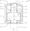
- FIG. 1 is an exemplary illustration showing a top view of a longitudinal end platform assembly 100 with indicia 300 .
- a distal end of the opposed ends of a substantially longitudinal machine structure 201 is shown as a dashed line.
- a distal end of the longitudinal end platform assembly 100 shall be the end opposed to the dashed line representing the machine structure 201
- the proximal end of the platform assembly 100 shall be the edge of the platform 101 closest to the dashed line just described.
- end platform assembly 100 is substantially symmetrical about the central longitudinal axis of the machine 200 and the description of a functional component or feature called out in any drawing on one side of the assembly may similarly apply to the component that is mirrored on the opposed side of the central longitudinal axis of the end platform assembly 100 .
- the end platform assembly 100 therefore comprises a substantially longitudinal platform 101 shown with a varying geometry to be fully described herein, and handles projecting laterally from and affixed to the platform 100 .
- the handles may be affixed to the machine structure proximal to the longitudinal end platform 101 .
- the platform 101 provides for a plurality of gripping surfaces that allow exercisers 400 to grasp the platform 101 in many positions to perform various exercises.
- the gripping surfaces may be substantially aligned with the central longitudinal axis of the exercise machine comprising a medial gripping surface 102 , and a lateral gripping surface 104 ; with the space formed between the lateral edge of the gripping surfaces and the handles being of a sufficient dimension to allow a typical hand to be inserted so that the fingers of the hand may wrap the sides and bottom of the platform 101 for gripping.
- Additional griping surfaces substantially aligned with the transverse axis of the machine 200 are provided; the gripping surfaces being a transverse gripping surface 103 and a transverse pushing surface 105 .
- the gripping surface 103 and pushing surface 105 just described may correspondingly become a pushing surface and gripping surface dependent on whether the exerciser 400 is positioned off of and facing back towards the machine 200 , or positioned on the machine 200 facing toward the distal end of the platform 101 .
- a machine 200 with a reciprocating platform resistance biased toward one given end will influence whether an exerciser 400 has to push or pull against the resistance bias as the means to move the reciprocating platform against the biasing force.
- the handles 106 , 107 , 108 , 109 , 110 , 111 , 112 being of a preferred cross-sectional geometry to allow for easy grasping with a hand, provide for a significantly large number of gripping positions and combinations of positions as may be used for various exercises. More specifically, the handles 106 , 107 , 108 , 109 , 110 , 111 , 112 may comprise a distal transverse handle 106 , a distal corner handle 107 , a distal side handle 108 , a middle transverse handle 109 , a middle side handle 110 , a proximal corner handle 111 and a proximal transverse handle 112 .
- handles 106 , 107 , 108 , 109 , 110 , 111 , 112 may be utilized in different embodiments, to suit the needs of different exercisers 400 , or to accommodate different types of exercise machines 200 .
- the novel structure just described provides for performing numerous exercises that could not be performed before the invention of the structure in the drawing; the previous unavailability of such a structure possibly causing novice exercisers to become confused by the complexity of the many gripping surfaces when a class instructor directs them to change exercise positions. Therefore, it is preferable that various indicia 300 be provided on the end platform assembly 100 to enable an instructor to give clear and efficient direction regarding the body placement or grip positioning during exercising.
- the indicia 100 shown in the figures and described herein is merely exemplary and thus not meant to be limiting.
- the indicia 100 may include any visible material either connected to the end platform 101 or integral with the end platform 101 , such as but not limited to any combination of colors, textures, indicator graphics, and alpha or numeric identifiers.
- the indicia 100 may comprise stickers or materials printed directly on the end platform 101 .
- the indicia 100 are shown as comprising dotted lines and letters.
- the indicia 100 could in other embodiments comprise symbols, numbers, logos, drawings, or the like.
- FIG. 2 is an exemplary illustration showing an isometric view of an exercise machine 200 with a longitudinal end platform 101 ; the end platform 101 being one of a plurality of components of the end platform assembly 100 previously described.
- the end platform assembly 100 is affixed at one distal end of a substantially longitudinal exercise machine 200 comprising a machine base 202 , a longitudinal machine structure 201 extending substantially the length of the machine 200 , a wide end platform 204 , and a reciprocating platform 205 slidable along substantially the length of the machine structure 201 between the longitudinal end platform 101 and the wide end platform 204 .
- the reciprocating platform 205 is preferably movable on a plurality of attached wheel assemblies in contact with parallel tracks aligned with the longitudinal axis of, and integral with, the machine structure 201 .
- One or more actuators 203 may be provided to allow one end of the machine 200 to be raised to various preferred distances above the floor to adjust an angle between the machine 200 and the ground surface. Each actuator 203 may be positioned on the opposed sides of the longitudinal axis of the machine 200 ; thereby providing for repositioning of the reciprocating and end platforms 101 , 204 , 205 along a non-horizontal plane.
- exercisers 400 have a variety of touch points to mount or dismount the machine 200 and to stabilize during exercise.
- Various handle assemblies 206 , 207 may be affixed to the exercise machine 200 , including a front handle assembly 207 , and a variation shown as a back handle assembly 206 .
- Handle assemblies 206 , 207 are shown adjacent to the wide end platform 204 or the longitudinal end platform 101 . Positioning of the handle assembles 206 , 207 may vary in different embodiments.
- FIG. 3A is an exemplary illustration showing a top view of an exercise machine 200 with a longitudinal end platform 101 , and adjacent and lateral thereto, a pair of back handle assemblies 206 .
- the exercise machine 200 provides for a machine base 202 , a longitudinal machine structure 201 , and a reciprocating platform 205 movable substantially between the longitudinal end platform 101 and a wide end platform 204 at the opposed end of the machine 200 .
- a pair of front handle assemblies 207 is illustrated as positioned adjacent to the wide end platform 204 .
- FIG. 3B is an exemplary illustration showing a top view of an exercise machine 200 with a reciprocating platform 205 , a longitudinal machine structure 201 , a longitudinal end platform 101 , and wide end platform 204 affixed to substantially opposed ends of the machine structure 201 .
- a reciprocating platform outline 208 shown in the drawing as a dashed line is provided to illustrate one of many movable positions of the reciprocating platform.
- FIG. 4A is an exemplary illustration showing a side view of an exercise machine with a longitudinal end platform.
- a machine structure 201 is movably affixed to a machine base 202 by a universal joint 209 and a pair of actuators 203 positioned at mirror image locations on opposed sides transverse to the longitudinal axis of the machine structure 201 .
- a wide end platform 204 is affixed to substantially the front end of the machine structure 201
- a longitudinal end platform assembly 100 is affixed to the opposed end of the machine structure 201 .
- a reciprocating platform 205 is movable substantially the length of the machine structure 201 between the wide end platform 204 and longitudinal end platform 101 .
- a biasing means not shown but affixed between the reciprocating platform 205 and the machine structure proximal to the wide end platform 204 , induces a resistance force R in the direction of the arrow.
- Exercisers 400 move the reciprocating platform 205 in a direction opposed to the resistance force as a means of exercising.
- Front handles assemblies 207 and back handle assemblies 206 may be used by exercisers 400 to mount, dismount or exercise upon the machine 200 .
- FIG. 4B is an exemplary illustration showing a side view of an exerciser 400 positioned on a tilted exercise machine 200 gripping the handles of a longitudinal end platform assembly 100 .
- a pair of actuators 203 is shown extended, thereby lifting one end of the machine 200 at an acute angle relative to the horizontal plane.
- a scissor stabilizer 210 provides for additional stability of the machine structure 201 while elevated.
- the exerciser 400 grips the longitudinal end platform assembly 100 , and with the knees solidly positioned on the reciprocating platform 205 , pulls the platform 101 in a direction opposed to the direction of the resistance bias arrow, with a force exceeding the resistance force R.
- FIG. 5 is an exemplary illustration showing a back view of an exercise machine 200 with a longitudinal end platform assembly 100 on the proximal end of the machine 200 .
- a pair of back handle assemblies 206 is shown affixed adjacent to and on opposed sides of the longitudinal end platform assembly 100 .
- a machine structure 201 is supported at an elevation above a machine base 202 by means of a pair of actuators 203 on the proximal end of the machine, and a universal joint 209 at a distal position on the machine.
- a pair of front handle assemblies 207 is shown positioned at the distal end of the exercise machine.
- FIG. 6 is an exemplary illustration showing a top view of an exercise machine 200 with two longitudinal end platforms 100 positioned at opposed ends of the machine structure 201 .
- a reciprocating platform 205 is movable substantially the distance between the end platforms 100 along a machine structure 201 .
- a longitudinal end platform 101 has been affixed to both opposed ends of the machine 200 . It should be appreciated that, in some embodiments, the exercise machine 200 may include only a single longitudinal end platform 101 on either of its opposed ends.
- FIG. 7A is an exemplary illustration showing a top view of a longitudinal end platform assembly 100 comprising a longitudinal end platform 101 , handles 106 , 107 , 108 , 109 , 110 , 111 , 112 as previously described, and as points of reference, dashed lines to indicate the position of a pair of back handle assemblies 206 and a longitudinal machine structure 201 .
- FIG. 7B is an exemplary illustration showing a top view of one variation of handle 106 , 107 , 108 , 109 , 110 , 111 , 112 positioning on a longitudinal end platform 101 .
- an exerciser 400 is shown positioned for a certain exercise with a left hand 401 gripping a middle transverse handle 109 and a right hand 402 gripping a proximal transverse handle 112 .
- FIG. 7C is an exemplary illustration showing a top view of a second variation of hand positioning on a longitudinal end platform 101 .
- an exerciser 400 is shown positioned for a certain exercise with a left hand 401 and right hand 402 gripping their respective left and right distal transverse handles 106 .
- FIG. 7D is an exemplary illustration showing a top view of another variation of hand positioning on a longitudinal end platform 101 .
- an exerciser 400 is shown positioned for a certain exercise with a left hand 401 gripping a proximal transverse handle 112 and a right hand 402 gripping a middle side handle 110 .
- FIG. 7E is an exemplary illustration showing a top view of another variation of hand positioning on a longitudinal end platform 101 .
- an exerciser 400 is shown positioned for a certain exercise with a left hand 401 and right hand 402 gripping their respective left and right media gripping surfaces 102 .
- FIG. 7F is an exemplary illustration showing a top view of another variation of hand positioning on a longitudinal end platform 101 .
- an exerciser 400 is shown positioned for a certain exercise with a left hand 401 and right hand 402 gripping their respective left and right middle side handles 110 .
- FIG. 7G is an exemplary illustration showing a top view of another variation of hand positioning on a longitudinal end platform 101 .
- an exerciser 400 is shown positioned for a certain exercise with a left hand 401 and right hand 402 gripping their respective left and right distal side handles 108 .
- FIG. 7H is an exemplary illustration showing a top view of yet another variation of hand positioning on a longitudinal end platform 101 .
- an exerciser 400 is shown positioned for a certain exercise with a left hand 401 gripping a middle transverse handle 109 and right hand 402 gripping a middle side handle 110 .
- FIG. 7I is an exemplary illustration showing a top view of another variation of hand positioning on a longitudinal end platform 101 .
- an exerciser 400 is shown positioned for a certain exercise with a left hand 401 gripping a right middle transverse handle 109 and right hand 402 gripping a left middle transverse handle 109 .
- an exerciser 400 performing an exercise with the hands 401 , 402 positioned as shown is preferably positioned standing on the floor beyond the distal end of the machine 200 , facing back towards substantially the entire exercise machine 200 .
- FIG. 7J is an exemplary illustration showing a top view of an accessory attached to a longitudinal end platform 101 .
- the novel longitudinal end platform 101 provides for the removable attachment of various exercise accessories that support the ability to perform an increased scope of exercises upon the machine 200 .
- the drawing shows a pair of resistance training accessories 211 removably affixed to the longitudinal end platform assembly 100 and/or distal end of the machine structure 201 within the open space created between the lateral edges of the longitudinal platform 101 , the distal transverse handles 106 , middle transverse handles 109 and the distal side handles 108 .
- the accessories just described provide for individual arm resistance training by means of pull cables with handles 212 , the cables extendible in opposition to a resistance force from, and retractable back into the resistance training accessories. It should be appreciated that a wide range of accessories may be utilized, and that the description of resistance training accessories 211 is merely for exemplary purposes and should not be construed as limiting in any manner.
- FIG. 7K is an exemplary illustration showing a top view of an exerciser 400 in the supine position on a resistance exercise machine 200 . It is sometimes preferred to position the upper body in a stationary position upon the longitudinal end platform 101 while using the lower body to exercise against the resistance force provided by the reciprocating platform 205 .
- an exerciser 400 is shown positioned with the upper body in a supine position, with the left and right hands 401 , 402 gripping the middle transverse handles 109 for support and stability. As can be readily seen, a substantial portion of the upper body of the exerciser 400 is supported on the longitudinal end platform assembly 100 .
- FIG. 7L is an exemplary illustration showing a top view of an exerciser 400 repositioned in the supine position on a resistance exercise machine 200 .
- the exerciser 400 is repositioned closer to the distal end of the platform 101 when compared to the previous position FIG. 7K ; with the left and right hands 401 , 402 gripping the distal transverse handles 106 .
- Such a position may provide for even more upper body support as may be desired for higher intensity exercising.
- upper body positioning on the longitudinal end platform 101 is not limited to supine positioning, and that prone or lateral recumbent positions may also be used when performing exercises requiring such body positioning.
- FIG. 8A is an exemplary illustration showing a top view of an exemplary exercise machine 200 with a longitudinal end platform 101 .
- the exercise machine 200 may comprise a longitudinal end platform assembly 100 and a wide end platform 204 .
- a dashed line illustrates one position of a reciprocating platform 205 .
- an exercise machine 200 as previously described is shown using dashed reference lines.
- the exercise machine 200 is may be comprised of a rectilinear geometry with a length L shown being a substantially larger dimension as its width W.
- FIG. 8B is an exemplary illustration showing an enlarged top view of a longitudinal end platform assembly 100 and a traditional wide end platform 204 of an exercise machine 200 .
- a longitudinal machine structure 201 is shown as a broken dashed line, the remainder of the machine 200 being omitted so as to not obscure the description of elements in the drawing.
- a traditional end platform of an exercise machine 200 may be described by length and width dimensions; the length being the dimension measured across the platform in a line substantially parallel to the longitudinal axis of the exercise machine and the width being the dimension measured across the platform in a line substantially normal to the longitudinal axis of the machine.
- the width of the wide end platform 204 is shown with a dimension W 2 .
- the length of the wide end platform 204 is shown with a dimension expressed as W 2 ⁇ Y, where W 2 is the width of the platform as just described, and Y is a dimension greater than zero.
- An improved longitudinal end platform assembly 100 is shown with an overall width expressed as W 1 , and the length as measured across the platform assembly 100 in a line substantially parallel to the longitudinal axis of the exercise machine 200 being expressed as W 1 +X, where X is a dimension greater than zero.
- the longitudinal platform 101 of the platform assembly 100 is shown with a major length dimension as substantially the same as the major length of the assembly expressed as W 1 +X, with a major width of the platform 101 being a dimension measured across the platform 101 in a line substantially normal to the longitudinal axis of the machine 200 expressed as W 1 ⁇ Z, where Z is a dimension greater than zero. Therefore, as is shown in the drawing, the longitudinal platform 101 , as well as the longitudinal platform assembly 100 , both have length dimensions that are greater than their width dimensions.
- FIG. 9A is an exemplary illustration showing the top view of an exercise machine 200 with a longitudinal end platform 101 .
- An exercise machine 200 as previously described is shown as dashed lines to prevent obscuring the longitudinal end platform 101 of the longitudinal end platform assembly.
- a target 301 is shown as a reference point for subsequent discussion.
- FIG. 9B is an exemplary illustration showing the top view of an exerciser 400 positioned supine on an exercise machine 200 with the upper body substantially positioned on a longitudinal end platform 101 , and the lower body substantially supported by a reciprocating platform 205 .
- a target 301 is shown generally over the cervical spine of the exerciser, with the exerciser's shoulders 403 preferably positioned over the major width area of the longitudinal end platform.
- the longitudinal end platform 101 is partially obscured by the exerciser 400 , and is therefore not shown in full.
- FIG. 9C is an exemplary illustration showing the platform-supported portions 404 of the upper body of an exerciser 400 .
- a tenet of the Lagree Method of exercising is to maximize spinal alignment and support throughout exercises performed in the machine 200 .
- a target 301 is shown to illustrate the approximate cervical spinal area of the exerciser 400 as previously described and referenced.
- a hash line 204 is shown as the perimeter outline of a wide end platform 204 as previously described, overlaid on the exerciser 400 to illustrate the approximate contact area between the exerciser's 400 back and the wide end platform 204 , generally extending from the upper cervical vertebra to the mid thoracic area. It should be noted that this general description may vary depending on the physical size of the exerciser 400 .
- an improved longitudinal end platform 101 is shown as a double line, extending substantially from above the exerciser's 400 head, nearly to the upper lumbar area of the spine. It can be readily seen that the improved longitudinal end platform 101 just described importantly supports the head that was not supported by traditional wide end platforms, and supports a larger portion of the spine, the additional portions of the upper body provided by the improved longitudinal end platform 101 when compared to the traditional wide end platform therefore shown as cross-hatched sections 404 .
- the end platform 101 may comprise a body portion and a head portion.
- the body portion may provide support for the body of the exerciser 400 , such as the shoulders and upper back.
- the head portion may provide support for the head of the exercise 400 .
- the body portion of the end platform 101 may be wider than the head portion as shown in the figures.
- the head portion may extend outwardly from a central point on the end of the body portion so that the head portion is centered with respect to the body portion of the end platform 101 .
- substantially longitudinal resistance exercise machines 200 providing for a reciprocating platform 205 and one or more end platforms 101 , 204 can vary significantly in overall dimensions, and further, exercisers 400 vary significantly in size.
- the actual dimensions of the longitudinal end platform 101 as described herein are not meant to be limiting. Although the figures illustrate that the length dimension is greater than the width dimension of the end platforms 101 , it should be appreciated that other configurations may be utilized.
- the various embodiments of present invention as described provide for a new and novel exercise machine end platform that provides substantially more exerciser support, and introduce a large number of previously unavailable gripping positions exercisers may use to perform an expanded number of exercises that previously could not be safely performed on an exercise machine with a traditional wide end platform.
- the longitudinal end platform assembly provides for the attachment of various exercise accessories.
Abstract
An End Platform for an Exercise Machine for increased support of an exerciser's spine, neck and head which allows for an expanded scope of exercises that cannot otherwise be performed on the machine without the improved platform. The End Platform for an Exercise Machine generally includes a novel, ergonomically improved stationary platform affixed to at least one opposed end of a substantially longitudinal exercise machine that includes at least a resistance biased reciprocating platform. The improved end platform provides for increased support of exercisers' spine, neck and head, thereby allowing for an expanded scope of exercises that cannot otherwise be performed on the machine without the improved platform, and further provides for the attachment of new and novel exercise equipment accessories to the exercise machine.
Description
The present application is a continuation of U.S. application Ser. No. 16/202,330 filed on Nov. 28, 2018 which issues on Dec. 8, 2020 as U.S. Pat. No. 10,857,420, which claims priority to U.S. Provisional Application No. 62/591,549 filed Nov. 28, 2017. Each of the aforementioned patent applications, and any applications related thereto, is herein incorporated by reference in their entirety.
Not applicable to this application.
Example embodiments in general relate to an end platform for an exercise machine for increased support of an exercisers' spine, neck and head which allows for an expanded scope of exercises that cannot otherwise be performed on the machine without the improved platform.
There has thus been outlined, rather broadly, some of the embodiments of the end platform for an exercise machine in order that the detailed description thereof may be better understood, and in order that the present contribution to the art may be better appreciated. There are additional embodiments of the end platform for an exercise machine that will be described hereinafter and that will form the subject matter of the claims appended hereto. In this respect, before explaining at least one embodiment of the end platform for an exercise machine in detail, it is to be understood that the end platform for an exercise machine is not limited in its application to the details of construction or to the arrangements of the components set forth in the following description or illustrated in the drawings. The end platform for an exercise machine is capable of other embodiments and of being practiced and carried out in various ways. Also, it is to be understood that the phraseology and terminology employed herein are for the purpose of the description and should not be regarded as limiting.
Resistance based exercise machines with a reciprocating, spring biased exercise platform have been commercially available for many years, and are well known to those in the fitness industry. For instance, various exercise machines with a spring biased substantially horizontal reciprocating platform are used to perform exercises in accordance with the teachings of the Pilates Method or the Lagree Method, both methods being practiced worldwide.
Such exercise machines comprise a substantially longitudinal structure, a platform that reciprocates on tracks or rails substantially between the opposed ends of the longitudinal structure, and a biasing means such as a plurality of springs or elastic ropes that removably attach the reciprocating platform to one end of the longitudinal structure. Exercises are performed by exerting a force against the reciprocating platform in opposition to the resistance induced against the platform by the biasing means.
The Lagree Method of exercising has, over the years, broadened to include the practice of new and novel exercises that were previously impossible to perform on traditional Pilates machines and, correspondingly continued to advance the art through innovative machine designs that provided for the performance of an ever expanding repertoire of unique, beneficial exercises, many of which are performed by an exerciser only partially positioned on the machine, and partially positioned on the floor of the exercise facility.
The Lagree Method and the Pilates Method similarly teach maintaining spinal alignment throughout the exercise routine, but substantially differ in that the history of the Pilates Method has kept the exerciser positioned almost entirely on the reciprocating platform, while the Lagree Method continually moves the exerciser from a position on the reciprocating platform to positions that require use of stationary platforms affixed at substantially the opposed ends of the longitudinal structure. However, there is a continued demand to overcome the functionality limitations of traditional exercise machines as a means to expand the scope of exercises not performable on exercise machines with end platforms of traditional geometry.
Those skilled in the art will appreciate the novelty and commercial value of an improved end platform that provides for enhanced spinal support, and for the attachment of various exercising accessories that significantly expanded the scope of exercises that could be safely and efficiently performed on the machine.
An example embodiment is directed to an end platform for an exercise machine. The various embodiments described herein provide for a novel, ergonomically improved stationary platform affixed to at least one opposed end of a substantially longitudinal exercise machine that comprises at least a resistance biased reciprocating platform. The improved end platform provides for increased support of exercisers' spine, neck and head, thereby allowing for an expanded scope of exercises that cannot otherwise be performed on the machine without the improved platform, and further provides for the attachment of new and novel exercise equipment accessories to the exercise machine.
There has thus been outlined, rather broadly, some of the embodiments of the end platform for an exercise machine in order that the detailed description thereof may be better understood, and in order that the present contribution to the art may be better appreciated. There are additional embodiments of the end platform for an exercise machine that will be described hereinafter and that will form the subject matter of the claims appended hereto. In this respect, before explaining at least one embodiment of the end platform for an exercise machine in detail, it is to be understood that the end platform for an exercise machine is not limited in its application to the details of construction or to the arrangements of the components set forth in the following description or illustrated in the drawings. The end platform for an exercise machine is capable of other embodiments and of being practiced and carried out in various ways. Also, it is to be understood that the phraseology and terminology employed herein are for the purpose of the description and should not be regarded as limiting.
Example embodiments will become more fully understood from the detailed description given herein below and the accompanying drawings, wherein like elements are represented by like reference characters, which are given by way of illustration only and thus are not limitative of the example embodiments herein.
Various aspects of specific embodiments are disclosed in the following description and related drawings. Alternate embodiments may be devised without departing from the spirit or the scope of the present disclosure. Additionally, well-known elements of exemplary embodiments will not be described in detail or will be omitted so as not to obscure relevant details. Further, to facilitate an understanding of the description, a discussion of several terms used herein follows.
The word “exemplary” is used herein to mean “serving as an example, instance, or illustration.” Any embodiment described herein as “exemplary” is not necessarily to be construed as preferred or advantageous over other embodiments.
The end platform assembly 100 therefore comprises a substantially longitudinal platform 101 shown with a varying geometry to be fully described herein, and handles projecting laterally from and affixed to the platform 100. As one variation, the handles may be affixed to the machine structure proximal to the longitudinal end platform 101. The platform 101 provides for a plurality of gripping surfaces that allow exercisers 400 to grasp the platform 101 in many positions to perform various exercises. The gripping surfaces may be substantially aligned with the central longitudinal axis of the exercise machine comprising a medial gripping surface 102, and a lateral gripping surface 104; with the space formed between the lateral edge of the gripping surfaces and the handles being of a sufficient dimension to allow a typical hand to be inserted so that the fingers of the hand may wrap the sides and bottom of the platform 101 for gripping.
Additional griping surfaces substantially aligned with the transverse axis of the machine 200 are provided; the gripping surfaces being a transverse gripping surface 103 and a transverse pushing surface 105. In practice, the gripping surface 103 and pushing surface 105 just described may correspondingly become a pushing surface and gripping surface dependent on whether the exerciser 400 is positioned off of and facing back towards the machine 200, or positioned on the machine 200 facing toward the distal end of the platform 101. Further, a machine 200 with a reciprocating platform resistance biased toward one given end will influence whether an exerciser 400 has to push or pull against the resistance bias as the means to move the reciprocating platform against the biasing force.
The handles 106, 107, 108, 109, 110, 111, 112, being of a preferred cross-sectional geometry to allow for easy grasping with a hand, provide for a significantly large number of gripping positions and combinations of positions as may be used for various exercises. More specifically, the handles 106, 107, 108, 109, 110, 111, 112 may comprise a distal transverse handle 106, a distal corner handle 107, a distal side handle 108, a middle transverse handle 109, a middle side handle 110, a proximal corner handle 111 and a proximal transverse handle 112. It should be appreciated that more or less handles 106, 107, 108, 109, 110, 111, 112 may be utilized in different embodiments, to suit the needs of different exercisers 400, or to accommodate different types of exercise machines 200.
The novel structure just described provides for performing numerous exercises that could not be performed before the invention of the structure in the drawing; the previous unavailability of such a structure possibly causing novice exercisers to become confused by the complexity of the many gripping surfaces when a class instructor directs them to change exercise positions. Therefore, it is preferable that various indicia 300 be provided on the end platform assembly 100 to enable an instructor to give clear and efficient direction regarding the body placement or grip positioning during exercising. The indicia 100 shown in the figures and described herein is merely exemplary and thus not meant to be limiting. The indicia 100 may include any visible material either connected to the end platform 101 or integral with the end platform 101, such as but not limited to any combination of colors, textures, indicator graphics, and alpha or numeric identifiers. The indicia 100 may comprise stickers or materials printed directly on the end platform 101. In the exemplary embodiment shown in FIG. 1 , the indicia 100 are shown as comprising dotted lines and letters. The indicia 100 could in other embodiments comprise symbols, numbers, logos, drawings, or the like.
One or more actuators 203 may be provided to allow one end of the machine 200 to be raised to various preferred distances above the floor to adjust an angle between the machine 200 and the ground surface. Each actuator 203 may be positioned on the opposed sides of the longitudinal axis of the machine 200; thereby providing for repositioning of the reciprocating and end platforms 101, 204, 205 along a non-horizontal plane.
It is sometimes preferred that exercisers 400 have a variety of touch points to mount or dismount the machine 200 and to stabilize during exercise. Various handle assemblies 206, 207 may be affixed to the exercise machine 200, including a front handle assembly 207, and a variation shown as a back handle assembly 206. Handle assemblies 206, 207 are shown adjacent to the wide end platform 204 or the longitudinal end platform 101. Positioning of the handle assembles 206, 207 may vary in different embodiments.
A reciprocating platform 205 is movable substantially the length of the machine structure 201 between the wide end platform 204 and longitudinal end platform 101. A biasing means not shown but affixed between the reciprocating platform 205 and the machine structure proximal to the wide end platform 204, induces a resistance force R in the direction of the arrow. Exercisers 400 move the reciprocating platform 205 in a direction opposed to the resistance force as a means of exercising. Front handles assemblies 207 and back handle assemblies 206 may be used by exercisers 400 to mount, dismount or exercise upon the machine 200.
Not meant to be limiting to one type of accessory, the drawing shows a pair of resistance training accessories 211 removably affixed to the longitudinal end platform assembly 100 and/or distal end of the machine structure 201 within the open space created between the lateral edges of the longitudinal platform 101, the distal transverse handles 106, middle transverse handles 109 and the distal side handles 108. The accessories just described provide for individual arm resistance training by means of pull cables with handles 212, the cables extendible in opposition to a resistance force from, and retractable back into the resistance training accessories. It should be appreciated that a wide range of accessories may be utilized, and that the description of resistance training accessories 211 is merely for exemplary purposes and should not be construed as limiting in any manner.
A traditional end platform of an exercise machine 200 may be described by length and width dimensions; the length being the dimension measured across the platform in a line substantially parallel to the longitudinal axis of the exercise machine and the width being the dimension measured across the platform in a line substantially normal to the longitudinal axis of the machine. In the drawing, the width of the wide end platform 204 is shown with a dimension W2. On the other hand, the length of the wide end platform 204 is shown with a dimension expressed as W2 −Y, where W2 is the width of the platform as just described, and Y is a dimension greater than zero. By means of this description which defines traditional machine end platforms, it can be readily understood that the platform 101 is wider than it is long. However, in other embodiments, the reverse could be true, with the platform 101 being longer than it is wide.
An improved longitudinal end platform assembly 100 is shown with an overall width expressed as W1, and the length as measured across the platform assembly 100 in a line substantially parallel to the longitudinal axis of the exercise machine 200 being expressed as W1+X, where X is a dimension greater than zero. By means of this description which defines an improved longitudinal end platform 101, it can be readily understood that the platform assembly 100 that includes handles 106, 107, 108, 109, 110, 111, 112 as shown is longer than it is wide.
Further, the longitudinal platform 101 of the platform assembly 100 is shown with a major length dimension as substantially the same as the major length of the assembly expressed as W1+X, with a major width of the platform 101 being a dimension measured across the platform 101 in a line substantially normal to the longitudinal axis of the machine 200 expressed as W1 −Z, where Z is a dimension greater than zero. Therefore, as is shown in the drawing, the longitudinal platform 101, as well as the longitudinal platform assembly 100, both have length dimensions that are greater than their width dimensions.
For reference purposes, a target 301 is shown to illustrate the approximate cervical spinal area of the exerciser 400 as previously described and referenced. A hash line 204 is shown as the perimeter outline of a wide end platform 204 as previously described, overlaid on the exerciser 400 to illustrate the approximate contact area between the exerciser's 400 back and the wide end platform 204, generally extending from the upper cervical vertebra to the mid thoracic area. It should be noted that this general description may vary depending on the physical size of the exerciser 400.
The perimeter outline of an improved longitudinal end platform 101 is shown as a double line, extending substantially from above the exerciser's 400 head, nearly to the upper lumbar area of the spine. It can be readily seen that the improved longitudinal end platform 101 just described importantly supports the head that was not supported by traditional wide end platforms, and supports a larger portion of the spine, the additional portions of the upper body provided by the improved longitudinal end platform 101 when compared to the traditional wide end platform therefore shown as cross-hatched sections 404.
As illustrated, the end platform 101 may comprise a body portion and a head portion. The body portion may provide support for the body of the exerciser 400, such as the shoulders and upper back. The head portion may provide support for the head of the exercise 400. The body portion of the end platform 101 may be wider than the head portion as shown in the figures. The head portion may extend outwardly from a central point on the end of the body portion so that the head portion is centered with respect to the body portion of the end platform 101.
It should be noted that substantially longitudinal resistance exercise machines 200 providing for a reciprocating platform 205 and one or more end platforms 101, 204 can vary significantly in overall dimensions, and further, exercisers 400 vary significantly in size. The actual dimensions of the longitudinal end platform 101 as described herein are not meant to be limiting. Although the figures illustrate that the length dimension is greater than the width dimension of the end platforms 101, it should be appreciated that other configurations may be utilized.
As can now be appreciated by those skilled in the art, the various embodiments of present invention as described provide for a new and novel exercise machine end platform that provides substantially more exerciser support, and introduce a large number of previously unavailable gripping positions exercisers may use to perform an expanded number of exercises that previously could not be safely performed on an exercise machine with a traditional wide end platform. Further, the longitudinal end platform assembly provides for the attachment of various exercise accessories.
Although specific embodiments have been illustrated and described herein, it will be appreciated by those of ordinary skill in the art that a wide variety of alternate and/or equivalent implementations may be substituted for the specific embodiments shown and described without departing from the scope of the present disclosure. This application is intended to cover any adaptations or variations of the embodiments discussed herein.
Claims (15)
1. An exercise machine, comprising:
a frame having a first end, a second end opposite of the first end, and a longitudinal axis extending therebetween;
a reciprocating platform movably positioned upon the frame, wherein the reciprocating platform is adapted to be movable along a portion of the longitudinal axis and wherein the reciprocating platform includes an upper surface;
a first tension member adapted to be connected to the reciprocating platform to provide a tension force to the reciprocating platform;
an end platform attached to the frame near the first end of the frame, wherein the end platform includes an upper surface, an outer edge, and an inner edge, wherein the inner edge of the end platform faces a direction generally towards the reciprocating platform, wherein the outer edge of the end platform faces a direction generally away from the reciprocating platform;
wherein the end platform includes a main support portion and an extended portion extending from the main support portion towards the outer edge of the end platform, wherein the extended portion is narrower than the main support portion, wherein the extended portion is elongated, wherein the extended portion extends along the longitudinal axis, wherein the extended portion has a first side and a second side opposite of the first side, and wherein the end platform has a T-shaped structure formed by the main support portion and the extended portion; and
a plurality of gripping surfaces on the end platform adapted to be grasped by an exerciser to perform various exercises;
wherein the plurality of gripping surfaces comprises a first medial gripping surface on the first side of the extended portion of the end platform and a second medial gripping surface on the second side of the extended portion of the end platform opposite of the first medial gripping surface, wherein the first medial gripping surface and the second medial gripping surface are each parallel with respect to the longitudinal axis;
wherein the plurality of gripping surfaces further comprises a first transverse gripping surface on the main support portion of the end platform, and a second transverse gripping surface on the main support portion of the end platform;
a plurality of handles connected to the end platform, wherein each of the plurality of handles is adapted to be grasped by the exerciser, wherein the plurality of handles comprises a first distal transverse handle, a second distal transverse handle, a first middle transverse handle, and a second middle transverse handle;
wherein the first middle transverse handle extends outwardly from the first side of the extended portion of the end platform and wherein the second middle transverse handle extends outwardly from the second side of the extended portion of the end platform;
wherein the first middle transverse handle is parallel to the first transverse gripping surface, wherein the first middle transverse handle faces the first transverse gripping surface of the main support portion; and
wherein the second middle transverse handle is parallel to the second transverse gripping surface, wherein the second middle transverse handle faces the second transverse gripping surface.
2. The exercise machine of claim 1 , wherein the first transverse gripping surface and the second transverse gripping surface are each transverse with respect to the longitudinal axis.
3. The exercise machine of claim 1 , wherein the first distal transverse handle is connected to the first side of the extended portion of the end platform and the second distal transverse handle is connected to the second side of the extended portion of the end platform.
4. The exercise machine of claim 1 , wherein the first distal transverse handle and the second distal transverse handle are each perpendicular with respect to the longitudinal axis.
5. The exercise machine of claim 1 , wherein the plurality of handles further comprises a first distal side handle and a second distal side handle, wherein the first distal side handle and the second distal side handle are each parallel with respect to the longitudinal axis.
6. The exercise machine of claim 1 , wherein the plurality of gripping surfaces further comprises a first lateral gripping surface and a second lateral gripping surface.
7. An exercise machine, comprising:
a frame having a first end, a second end opposite of the first end, and a longitudinal axis extending therebetween;
a reciprocating platform movably positioned upon the frame, wherein the reciprocating platform is adapted to be movable along a portion of the longitudinal axis and wherein the reciprocating platform includes an upper surface;
a first tension member adapted to be connected to the reciprocating platform to provide a tension force to the reciprocating platform;
an end platform attached to the frame near the first end of the frame, wherein the end platform includes an upper surface, an outer edge, and an inner edge, wherein the inner edge of the end platform faces a direction generally towards the reciprocating platform, wherein the outer edge of the end platform faces a direction generally away from the reciprocating platform;
wherein the end platform includes a main support portion and an extended portion extending from the main support portion towards the outer edge of the end platform, wherein the extended portion is narrower than the main support portion, wherein the extended portion is elongated, wherein the extended portion extends along the longitudinal axis, wherein the extended portion has a first side and a second side opposite of the first side, and wherein the end platform has a T-shaped structure formed by the main support portion and the extended portion; and
a plurality of gripping surfaces on the end platform adapted to be grasped by an exerciser to perform various exercises;
wherein the plurality of gripping surfaces comprises a first medial gripping surface on the first side of the extended portion of the end platform and a second medial gripping surface on the second side of the extended portion of the end platform opposite of the first medial gripping surface, wherein the first medial gripping surface and the second medial gripping surface are each parallel with respect to the longitudinal axis;
wherein the plurality of gripping surfaces further comprises a first transverse gripping surface on the main support portion of the end platform, and a second transverse gripping surface on the main support portion of the end platform, wherein the first transverse gripping surface and the second transverse gripping surface are each transverse with respect to the longitudinal axis;
a plurality of handles connected to the end platform, wherein each of the plurality of handles is adapted to be grasped by the exerciser, wherein the plurality of handles comprises a first distal transverse handle, a second distal transverse handle, a first middle transverse handle, and a second middle transverse handle;
wherein the first distal transverse handle and the second distal transverse handle are each perpendicular with respect to the longitudinal axis;
wherein the first middle transverse handle extends outwardly from the first side of the extended portion of the end platform and wherein the second middle transverse handle extends outwardly from the second side of the extended portion of the end platform;
wherein the first middle transverse handle is parallel to the first transverse gripping surface, wherein the first middle transverse handle faces the first transverse gripping surface of the main support portion; and
wherein the second middle transverse handle is parallel to the second transverse gripping surface, wherein the second middle transverse handle faces the second transverse gripping surface.
8. The exercise machine of claim 7 , wherein the first distal transverse handle is connected to the first side of the extended portion of the end platform and the second distal transverse handle is connected to the second side of the extended portion of the end platform.
9. The exercise machine of claim 7 , wherein the plurality of handles further comprises a first distal side handle and a second distal side handle, wherein the first distal side handle and the second distal side handle are each parallel with respect to the longitudinal axis.
10. The exercise machine of claim 7 , wherein the plurality of gripping surfaces further comprises a first lateral gripping surface and a second lateral gripping surface.
11. An exercise machine, comprising:
a frame having a first end, a second end opposite of the first end, and a longitudinal axis extending therebetween;
a reciprocating platform movably positioned upon the frame, wherein the reciprocating platform is adapted to be movable along a portion of the longitudinal axis and wherein the reciprocating platform includes an upper surface;
a first tension member adapted to be connected to the reciprocating platform to provide a tension force to the reciprocating platform;
an end platform attached to the frame and positioned near the first end of the frame, wherein the end platform includes a main support portion and an extended portion extending from the main support portion towards a distal edge of the end platform, wherein the extended portion has a longitudinal axis, wherein the extended portion is narrower than the main support portion, wherein the extended portion is elongated, wherein the extended portion has a first side and a second side opposite of the first side, and wherein the main support portion and the extended portion form a T-shaped structure;
a first medial gripping surface on the first side of the extended portion of the end platform and a second medial gripping surface on the second side of the extended portion of the end platform opposite of the first medial gripping surface, wherein the first medial gripping surface and the second medial gripping surface are each parallel with respect to the longitudinal axis;
a first transverse gripping surface on the main support portion of the end platform, and a second transverse gripping surface on the main support portion of the end platform;
a first middle transverse handle extending outwardly from the first side of the extended portion of the end platform and a second middle transverse handle extending outwardly from the second side of the extended portion of the end platform; and
wherein the first middle transverse handle is parallel to the first transverse gripping surface, wherein the first middle transverse handle faces the first transverse gripping surface of the main support portion;
wherein the second middle transverse handle is parallel to the second transverse gripping surface, wherein the second middle transverse handle faces the second transverse gripping surface.
12. The exercise machine of claim 11 , wherein the first transverse gripping surface and the second transverse gripping surface are each transverse with respect to the longitudinal axis.
13. The exercise machine of claim 11 , further comprising a first distal transverse handle connected to the first side of the extended portion of the end platform and a second distal transverse handle connected to the second side of the extended portion of the end platform.
14. The exercise machine of claim 13 , wherein the first distal transverse handle and the second distal transverse handle are each perpendicular with respect to the longitudinal axis.
15. The exercise machine of claim 11 , further comprising a first lateral gripping surface on a first side of the main support portion of the end platform and a second lateral gripping surface on the main support portion of the end platform.
Priority Applications (3)
| Application Number | Priority Date | Filing Date | Title |
|---|---|---|---|
| US17/113,231 US11298586B1 (en) | 2017-11-28 | 2020-12-07 | End platform for an exercise machine |
| US17/717,826 US11642567B1 (en) | 2017-11-28 | 2022-04-11 | End platform for an exercise machine |
| US18/194,997 US20230233902A1 (en) | 2017-11-28 | 2023-04-03 | End Platform for an Exercise Machine |
Applications Claiming Priority (3)
| Application Number | Priority Date | Filing Date | Title |
|---|---|---|---|
| US201762591549P | 2017-11-28 | 2017-11-28 | |
| US16/202,330 US10857420B2 (en) | 2017-11-28 | 2018-11-28 | End platform for an exercise machine |
| US17/113,231 US11298586B1 (en) | 2017-11-28 | 2020-12-07 | End platform for an exercise machine |
Related Parent Applications (1)
| Application Number | Title | Priority Date | Filing Date |
|---|---|---|---|
| US16/202,330 Continuation US10857420B2 (en) | 2017-11-28 | 2018-11-28 | End platform for an exercise machine |
Related Child Applications (1)
| Application Number | Title | Priority Date | Filing Date |
|---|---|---|---|
| US17/717,826 Continuation US11642567B1 (en) | 2017-11-28 | 2022-04-11 | End platform for an exercise machine |
Publications (1)
| Publication Number | Publication Date |
|---|---|
| US11298586B1 true US11298586B1 (en) | 2022-04-12 |
Family
ID=66634186
Family Applications (4)
| Application Number | Title | Priority Date | Filing Date |
|---|---|---|---|
| US16/202,330 Active 2038-12-05 US10857420B2 (en) | 2017-11-28 | 2018-11-28 | End platform for an exercise machine |
| US17/113,231 Active 2038-12-22 US11298586B1 (en) | 2017-11-28 | 2020-12-07 | End platform for an exercise machine |
| US17/717,826 Active US11642567B1 (en) | 2017-11-28 | 2022-04-11 | End platform for an exercise machine |
| US18/194,997 Pending US20230233902A1 (en) | 2017-11-28 | 2023-04-03 | End Platform for an Exercise Machine |
Family Applications Before (1)
| Application Number | Title | Priority Date | Filing Date |
|---|---|---|---|
| US16/202,330 Active 2038-12-05 US10857420B2 (en) | 2017-11-28 | 2018-11-28 | End platform for an exercise machine |
Family Applications After (2)
| Application Number | Title | Priority Date | Filing Date |
|---|---|---|---|
| US17/717,826 Active US11642567B1 (en) | 2017-11-28 | 2022-04-11 | End platform for an exercise machine |
| US18/194,997 Pending US20230233902A1 (en) | 2017-11-28 | 2023-04-03 | End Platform for an Exercise Machine |
Country Status (1)
| Country | Link |
|---|---|
| US (4) | US10857420B2 (en) |
Families Citing this family (19)
| Publication number | Priority date | Publication date | Assignee | Title |
|---|---|---|---|---|
| US10052518B2 (en) | 2015-03-17 | 2018-08-21 | Lagree Technologies, Inc. | Exercise machine monitoring and instruction system |
| US11745054B2 (en) | 2016-12-09 | 2023-09-05 | MILLZ, Inc. | Exercise device |
| US10974092B2 (en) | 2018-07-25 | 2021-04-13 | Lagree Technologies, Inc. | Adjustable exercise machine |
| US11000727B2 (en) | 2018-08-20 | 2021-05-11 | Lagree Technologies, Inc. | Exercise machine with levitated platform |
| US11446540B2 (en) | 2019-05-08 | 2022-09-20 | Lagree Technologies, Inc. | Exercise machine handle system |
| US11478677B2 (en) * | 2019-06-03 | 2022-10-25 | Lagree Technologies, Inc. | Exercise machine |
| US11439887B2 (en) | 2019-09-09 | 2022-09-13 | Lagree Technologies, Inc. | Exercise machine with visual guidance |
| TWI702072B (en) * | 2019-11-29 | 2020-08-21 | 昌祐科技國際股份有限公司 | Frame lifting mechanism for fitness equipment |
| US11433272B2 (en) * | 2020-01-16 | 2022-09-06 | Lagree Technologies, Inc. | Exercise machine handle system |
| US11911646B2 (en) | 2020-02-10 | 2024-02-27 | De Luna Studios, LLC | Exercise machine |
| USD946094S1 (en) | 2020-03-16 | 2022-03-15 | Lagree Technologies, Inc. | Exercise machine |
| US11213719B1 (en) | 2020-06-30 | 2022-01-04 | Lagree Technologies, Inc. | System and method of using two exercise machines |
| US11458355B2 (en) | 2020-08-25 | 2022-10-04 | Lagree Technologies, Inc. | Exercise machine |
| US11456623B2 (en) | 2020-11-04 | 2022-09-27 | Lagree Technologies, Inc. | Wireless power system for an exercise machine |
| US11465027B1 (en) | 2021-03-16 | 2022-10-11 | Lagree Technologies, Inc. | Exercise machine storage system |
| US11872441B2 (en) | 2021-06-15 | 2024-01-16 | Lagree Technologies, Inc. | Exercise machine rail system |
| USD993341S1 (en) | 2021-06-30 | 2023-07-25 | Lagree Technologies, Inc. | Exercise machine |
| US11931615B2 (en) | 2021-07-13 | 2024-03-19 | Lagree Technologies, Inc. | Exercise machine resistance selection system |
| US11465011B1 (en) | 2021-07-20 | 2022-10-11 | Lagree Technologies, Inc. | Exercise machine with adjustable platforms |
Citations (87)
| Publication number | Priority date | Publication date | Assignee | Title |
|---|---|---|---|---|
| US1621477A (en) | 1924-08-27 | 1927-03-15 | Pilates Joe | Gymnastic apparatus |
| US3770267A (en) | 1972-03-08 | 1973-11-06 | Carthy M Mc | Exercising machine having plural exercising implements thereon |
| US4759540A (en) | 1986-10-14 | 1988-07-26 | Industrial Technology Research Institute | Compact structure for a treadmill |
| US4798378A (en) | 1985-07-15 | 1989-01-17 | Jones Robert S | Rowing machine |
| US4911438A (en) | 1986-08-29 | 1990-03-27 | Verimark (Proprietary) Limited | Exercising machine |
| US5066005A (en) | 1990-10-01 | 1991-11-19 | Luecke Thomas W | Enhanced core movement training bench |
| US5263913A (en) | 1992-07-31 | 1993-11-23 | Boren John P | Exercise machine |
| US5358462A (en) | 1992-01-03 | 1994-10-25 | Calderone Michael P | Exercise apparatus |
| US5429567A (en) | 1993-11-01 | 1995-07-04 | Stamina Products, Inc. | Cross-country and downhill slalom skiing exercise machine |
| USD362700S (en) | 1994-07-05 | 1995-09-26 | Breibart Joan R | Physical exerciser |
| USD382319S (en) | 1996-04-12 | 1997-08-12 | Stamina Products, Inc. | Exerciser |
| US5681249A (en) | 1995-11-29 | 1997-10-28 | Endelman; Ken | Convertible exercise apparatus |
| US5833588A (en) | 1996-07-08 | 1998-11-10 | Connelly Iii; William L. | Hand-held resilient exerciser |
| US5885197A (en) | 1997-06-04 | 1999-03-23 | Barton; Jimmy | Exercise equipment |
| US5967955A (en) | 1997-05-02 | 1999-10-19 | Total Gym Fitness, Ltd. | Collapsible exercise device |
| US5997450A (en) | 1996-09-18 | 1999-12-07 | Wilkinson; William T. | Combination slant board and abdominal rocker |
| US6179753B1 (en) | 1998-10-14 | 2001-01-30 | Illinois Tool Works Inc. | Suspension system for exercise apparatus |
| US20010056011A1 (en) | 1999-03-11 | 2001-12-27 | Ken Endelman | Reformer exercise apparatus |
| US20030119635A1 (en) | 2001-12-26 | 2003-06-26 | Arbuckle Michael M. | Foldable transportable multiple function pilates exercise method and apparatus |
| US20040142800A1 (en) | 2003-01-17 | 2004-07-22 | Stamina Products, Inc. | Exercise apparatus with resilient foot support |
| WO2004096376A1 (en) | 2003-04-23 | 2004-11-11 | Solow Howard J | Foldable transportable multiple function pilates exercise apparatus and method |
| US20050085357A1 (en) | 2001-12-20 | 2005-04-21 | Ken Endelman | Reformer exercise apparatus having a non-rotating spring anchor bar |
| US20050124471A1 (en) | 2000-12-29 | 2005-06-09 | Wilkinson William T. | Total body exercise machine with adjustable railings and/or adjustable incline |
| US20050130810A1 (en) | 2003-12-02 | 2005-06-16 | Lenny Sands | Multi-purpose exercise device |
| US20050164856A1 (en) | 2004-01-09 | 2005-07-28 | Parmater Kim M. | Method and apparatus for performing pilates exercises |
| US20060046914A1 (en) | 2004-09-01 | 2006-03-02 | Balanced Body, Inc. | Reformer exercise apparatus foot bar support |
| US20060199712A1 (en) | 2005-03-01 | 2006-09-07 | Balanced Body, Inc. | Carriage for a collapsible reformer exercise apparatus |
| US7163500B2 (en) | 2003-11-25 | 2007-01-16 | Balanced Body, Inc. | Reformer exercise apparatus anchor bar assembly |
| US20070117693A1 (en) | 2005-11-23 | 2007-05-24 | Mihai Ilioi | Method and apparatus for lateral exercise |
| US20070129226A1 (en) | 2005-11-16 | 2007-06-07 | Shannon Leavitt | Exercise device |
| US20070219053A1 (en) | 2003-10-27 | 2007-09-20 | Stamina Products, Inc. | Exercise apparatus with resilient foot support |
| US20080070765A1 (en) | 2005-01-05 | 2008-03-20 | Ab Coaster Holdings, Inc. | Abdominal exercise machine |
| US20090111661A1 (en) | 2007-10-28 | 2009-04-30 | Hauser Stephen G | Pullup exercise assembly with rotatable handles and pivotable bar |
| US20100227748A1 (en) | 2009-03-06 | 2010-09-09 | Total Gym Fitness, Llc | Inclinable exercise device with abdominal crunch exercise accessory apparatus and method |
| US7803095B1 (en) | 2006-08-18 | 2010-09-28 | Lagree Sebastien A | Exercise machine |
| US7931570B2 (en) | 2006-01-30 | 2011-04-26 | Balanced Body, Inc. | Exercise device |
| US20110130258A1 (en) | 2005-04-07 | 2011-06-02 | Stamina Products, Inc. | Excercise apparatus and method |
| US20110143898A1 (en) | 2009-12-14 | 2011-06-16 | Hill-Rom Services, Inc. | Patient support apparatuses with exercise functionalities |
| US20110166002A1 (en) | 2006-07-17 | 2011-07-07 | Studio Moderna Sa | Multipurpose exercise system |
| US20110172069A1 (en) | 2010-01-12 | 2011-07-14 | Stamina Products, Inc. | Exercise apparatus with resilient foot support |
| US8249714B1 (en) | 2005-07-08 | 2012-08-21 | Customkynetics, Inc. | Lower extremity exercise device with stimulation and related methods |
| US20120295771A1 (en) | 2011-05-20 | 2012-11-22 | Lagree Sebastien A | Exercise machine |
| US20130196835A1 (en) | 2011-11-02 | 2013-08-01 | Howard Solow | Exercise Table |
| US20140011645A1 (en) | 2012-07-03 | 2014-01-09 | Keith Johnson | Multiple position exercise device |
| US20140100089A1 (en) | 2012-10-04 | 2014-04-10 | Reform 180, Inc. | Adaptive split carriage exercise reformer |
| US20140121079A1 (en) | 2011-05-20 | 2014-05-01 | The Superformers, Inc. | Exercise System with Positioning Markings |
| US20140121078A1 (en) | 2012-10-29 | 2014-05-01 | The Superformers, Inc. | Exercise Machine Tension System |
| US20140121076A1 (en) | 2012-10-29 | 2014-05-01 | The Superformers, Inc. | Pilates Machine Tension Device Support System |
| US20140141948A1 (en) | 2012-09-18 | 2014-05-22 | Rockit Body Pilates, Llc | Pilates reformer |
| US20140221182A1 (en) | 2013-02-01 | 2014-08-07 | Chieh-Jeh Lin | Multi-Functional Exercise Platform |
| US20150024914A1 (en) * | 2013-10-23 | 2015-01-22 | Spx Fitness, Inc. | Exercise Machine Carriage System |
| US20150057127A1 (en) | 2013-08-26 | 2015-02-26 | Spx Fitness, Inc. | Adjustable Exercise System |
| US20150065320A1 (en) | 2013-08-30 | 2015-03-05 | Brianne Anderson | Reformer |
| US20150065318A1 (en) * | 2013-10-25 | 2015-03-05 | Spx Fitness, Inc. | Exercise Machine Ergonomic Handle System |
| US20150072841A1 (en) | 2012-10-29 | 2015-03-12 | Spx Fitness, Inc. | Exercise Machine Cable Adjustment System |
| US20150141204A1 (en) * | 2013-11-18 | 2015-05-21 | Spx Fitness, Inc. | Self-Standing Weighted Pole System |
| US20150217164A1 (en) | 2014-02-04 | 2015-08-06 | Spx Fitness, Inc. | Pilates Exercise Routine System and Method |
| US20150220523A1 (en) | 2014-02-04 | 2015-08-06 | Spx Fitness, Inc. | Customizable Workout Video System |
| US20150246263A1 (en) | 2014-02-28 | 2015-09-03 | Total Gym Global Corp. | Functional body weight circuit training system and method of using exercise devices having a slidable incline |
| US20150343250A1 (en) | 2013-08-26 | 2015-12-03 | Spx Fitness, Inc. | Multi-axis Adjustable Exercise Machine |
| US20150360113A1 (en) | 2014-06-17 | 2015-12-17 | Spx Fitness, Inc. | Exercise Machine Rail System |
| US20150360068A1 (en) | 2013-08-26 | 2015-12-17 | Spx Fitness, Inc. | Exercise Machine Support System |
| US20150364058A1 (en) | 2014-06-17 | 2015-12-17 | Spx Fitness, Inc. | Interactive Exercise Instruction System and Method |
| US20150360083A1 (en) | 2014-06-17 | 2015-12-17 | Spx Fitness, Inc. | Exercise Machine Adjustable Resistance System and Method |
| US20150367166A1 (en) | 2012-10-29 | 2015-12-24 | Spx Fitness, Inc. | Exercise Machine Handle System |
| US20160059061A1 (en) | 2014-08-29 | 2016-03-03 | Spx Fitness, Inc. | Exercise Machine With Variable Resistance System |
| US20160059060A1 (en) | 2014-08-29 | 2016-03-03 | Spx Fitness, Inc. | Exercise Machine Reversible Resistance System |
| US20160096059A1 (en) | 2012-10-29 | 2016-04-07 | Spx Fitness, Inc. | Exercise Machine Carriage Handle System |
| US20160166870A1 (en) | 2013-08-26 | 2016-06-16 | SPX Fitness, Inc | Exercise Machine Inclination Device |
| US20160256733A1 (en) | 2012-10-29 | 2016-09-08 | Spx Fitness, Inc. | Multiple Position Locking Handle For An Exercise Machine |
| US20160271452A1 (en) | 2015-03-17 | 2016-09-22 | Spx Fitness, Inc. | Exercise Machine Monitoring And Instruction System |
| US20160311496A1 (en) * | 2015-04-22 | 2016-10-27 | David Atterbury | Stationary Bike Handlebar Riser |
| US20160361602A1 (en) | 2015-06-12 | 2016-12-15 | SPX Fitness, Inc | Bioelectrical Signal Controlled Exercise Machine System |
| US20170087397A1 (en) | 2013-08-26 | 2017-03-30 | Lagree Technologies, Inc. | Exercise Machine Support System |
| US20170100625A1 (en) | 2011-05-20 | 2017-04-13 | Lagree Technologies, Inc. | Exercise Machine Handle System |
| US20170113091A1 (en) | 2015-10-21 | 2017-04-27 | Spx Fitness, Inc. | Exercise Machine with Multiple Contact Surfaces |
| US20170157452A1 (en) | 2012-10-29 | 2017-06-08 | Lagree Technologies, Inc. | Exercise Machine Handle Indicia System |
| US20170209728A1 (en) | 2016-01-22 | 2017-07-27 | Lagree Technologies, Inc. | Exercise Machine Resistance Adjustment System |
| US20170296865A1 (en) | 2016-04-19 | 2017-10-19 | Lagree Technologies, Inc. | Tilting Exercise Machine |
| US20170340947A1 (en) | 2016-05-31 | 2017-11-30 | Lagree Technologies, Inc. | Exercise Machine Rail Indicia System |
| US20180015319A1 (en) | 2016-07-12 | 2018-01-18 | Lagree Technologies, Inc. | Exercise Machine with Electromagnetic Resistance Selection |
| US20180021621A1 (en) | 2016-07-22 | 2018-01-25 | Lagree Technologies, Inc. | Reversible Resistance Exercise Machine |
| US20180111020A1 (en) | 2016-10-20 | 2018-04-26 | Lagree Technologies, Inc. | Exercise Machine With Adjustable Handles |
| US20180111033A1 (en) | 2016-10-25 | 2018-04-26 | Lagree Technologies, Inc. | Exercise Machine Accessory System |
| US20180178053A1 (en) | 2016-12-23 | 2018-06-28 | Lagree Technologies, Inc. | Exercise Machine |
| US10046193B1 (en) | 2015-07-17 | 2018-08-14 | Rockitformer, LLC | Pilates exercise machine |
| US20180280782A1 (en) | 2017-03-09 | 2018-10-04 | Lagree Technologies, Inc. | System and Method for Networking Fitness Machines |
Family Cites Families (3)
| Publication number | Priority date | Publication date | Assignee | Title |
|---|---|---|---|---|
| US8323157B2 (en) | 2004-02-24 | 2012-12-04 | Total Gym Global Corp. | Method of using an exercise device having an adjustable incline |
| WO2007048082A2 (en) | 2005-10-14 | 2007-04-26 | Contemporary Designs, Co. | Treatment table and exercise device method and apparatus |
| US8585554B2 (en) | 2011-01-26 | 2013-11-19 | Flow-Motion Research and Development | Method and apparatus for electronically controlled resistance in exercise equipment |
-
2018
- 2018-11-28 US US16/202,330 patent/US10857420B2/en active Active
-
2020
- 2020-12-07 US US17/113,231 patent/US11298586B1/en active Active
-
2022
- 2022-04-11 US US17/717,826 patent/US11642567B1/en active Active
-
2023
- 2023-04-03 US US18/194,997 patent/US20230233902A1/en active Pending
Patent Citations (134)
| Publication number | Priority date | Publication date | Assignee | Title |
|---|---|---|---|---|
| US1621477A (en) | 1924-08-27 | 1927-03-15 | Pilates Joe | Gymnastic apparatus |
| US3770267A (en) | 1972-03-08 | 1973-11-06 | Carthy M Mc | Exercising machine having plural exercising implements thereon |
| US4798378A (en) | 1985-07-15 | 1989-01-17 | Jones Robert S | Rowing machine |
| US4911438A (en) | 1986-08-29 | 1990-03-27 | Verimark (Proprietary) Limited | Exercising machine |
| US4759540A (en) | 1986-10-14 | 1988-07-26 | Industrial Technology Research Institute | Compact structure for a treadmill |
| US5066005A (en) | 1990-10-01 | 1991-11-19 | Luecke Thomas W | Enhanced core movement training bench |
| US5358462A (en) | 1992-01-03 | 1994-10-25 | Calderone Michael P | Exercise apparatus |
| US5263913A (en) | 1992-07-31 | 1993-11-23 | Boren John P | Exercise machine |
| US5429567A (en) | 1993-11-01 | 1995-07-04 | Stamina Products, Inc. | Cross-country and downhill slalom skiing exercise machine |
| USD362700S (en) | 1994-07-05 | 1995-09-26 | Breibart Joan R | Physical exerciser |
| US5681249A (en) | 1995-11-29 | 1997-10-28 | Endelman; Ken | Convertible exercise apparatus |
| USD382319S (en) | 1996-04-12 | 1997-08-12 | Stamina Products, Inc. | Exerciser |
| US5833588A (en) | 1996-07-08 | 1998-11-10 | Connelly Iii; William L. | Hand-held resilient exerciser |
| US5997450A (en) | 1996-09-18 | 1999-12-07 | Wilkinson; William T. | Combination slant board and abdominal rocker |
| US5967955A (en) | 1997-05-02 | 1999-10-19 | Total Gym Fitness, Ltd. | Collapsible exercise device |
| US5885197A (en) | 1997-06-04 | 1999-03-23 | Barton; Jimmy | Exercise equipment |
| US6179753B1 (en) | 1998-10-14 | 2001-01-30 | Illinois Tool Works Inc. | Suspension system for exercise apparatus |
| US20010056011A1 (en) | 1999-03-11 | 2001-12-27 | Ken Endelman | Reformer exercise apparatus |
| US20050124471A1 (en) | 2000-12-29 | 2005-06-09 | Wilkinson William T. | Total body exercise machine with adjustable railings and/or adjustable incline |
| US20050085357A1 (en) | 2001-12-20 | 2005-04-21 | Ken Endelman | Reformer exercise apparatus having a non-rotating spring anchor bar |
| US20030119635A1 (en) | 2001-12-26 | 2003-06-26 | Arbuckle Michael M. | Foldable transportable multiple function pilates exercise method and apparatus |
| US20040142800A1 (en) | 2003-01-17 | 2004-07-22 | Stamina Products, Inc. | Exercise apparatus with resilient foot support |
| WO2004096376A1 (en) | 2003-04-23 | 2004-11-11 | Solow Howard J | Foldable transportable multiple function pilates exercise apparatus and method |
| US20080248935A1 (en) | 2003-04-23 | 2008-10-09 | Howard J Solow | Foldable Transportable Multiple Function Pilates Exercise Apparatus and Method |
| US20070219053A1 (en) | 2003-10-27 | 2007-09-20 | Stamina Products, Inc. | Exercise apparatus with resilient foot support |
| US7163500B2 (en) | 2003-11-25 | 2007-01-16 | Balanced Body, Inc. | Reformer exercise apparatus anchor bar assembly |
| US20050130810A1 (en) | 2003-12-02 | 2005-06-16 | Lenny Sands | Multi-purpose exercise device |
| US20050164856A1 (en) | 2004-01-09 | 2005-07-28 | Parmater Kim M. | Method and apparatus for performing pilates exercises |
| US20060046914A1 (en) | 2004-09-01 | 2006-03-02 | Balanced Body, Inc. | Reformer exercise apparatus foot bar support |
| US20080070765A1 (en) | 2005-01-05 | 2008-03-20 | Ab Coaster Holdings, Inc. | Abdominal exercise machine |
| US20060199712A1 (en) | 2005-03-01 | 2006-09-07 | Balanced Body, Inc. | Carriage for a collapsible reformer exercise apparatus |
| US20110130258A1 (en) | 2005-04-07 | 2011-06-02 | Stamina Products, Inc. | Excercise apparatus and method |
| US8249714B1 (en) | 2005-07-08 | 2012-08-21 | Customkynetics, Inc. | Lower extremity exercise device with stimulation and related methods |
| US20070129226A1 (en) | 2005-11-16 | 2007-06-07 | Shannon Leavitt | Exercise device |
| US20070117693A1 (en) | 2005-11-23 | 2007-05-24 | Mihai Ilioi | Method and apparatus for lateral exercise |
| US7931570B2 (en) | 2006-01-30 | 2011-04-26 | Balanced Body, Inc. | Exercise device |
| US20110166002A1 (en) | 2006-07-17 | 2011-07-07 | Studio Moderna Sa | Multipurpose exercise system |
| US7803095B1 (en) | 2006-08-18 | 2010-09-28 | Lagree Sebastien A | Exercise machine |
| US20090111661A1 (en) | 2007-10-28 | 2009-04-30 | Hauser Stephen G | Pullup exercise assembly with rotatable handles and pivotable bar |
| US20100227748A1 (en) | 2009-03-06 | 2010-09-09 | Total Gym Fitness, Llc | Inclinable exercise device with abdominal crunch exercise accessory apparatus and method |
| US20110143898A1 (en) | 2009-12-14 | 2011-06-16 | Hill-Rom Services, Inc. | Patient support apparatuses with exercise functionalities |
| US20110172069A1 (en) | 2010-01-12 | 2011-07-14 | Stamina Products, Inc. | Exercise apparatus with resilient foot support |
| US20140121079A1 (en) | 2011-05-20 | 2014-05-01 | The Superformers, Inc. | Exercise System with Positioning Markings |
| US8641585B2 (en) | 2011-05-20 | 2014-02-04 | Sebastien A. LaGree | Exercise machine |
| US20170100625A1 (en) | 2011-05-20 | 2017-04-13 | Lagree Technologies, Inc. | Exercise Machine Handle System |
| US20170157458A1 (en) | 2011-05-20 | 2017-06-08 | Lagree Technologies, Inc. | Exercise Machine Carriage System |
| US20170326406A1 (en) | 2011-05-20 | 2017-11-16 | Lagree Technologies, Inc. | Multiple Position Locking Handle For An Exercise Machine |
| US20170189740A1 (en) | 2011-05-20 | 2017-07-06 | Lagree Technologies, Inc. | Exercise machine handle system |
| US20120295771A1 (en) | 2011-05-20 | 2012-11-22 | Lagree Sebastien A | Exercise machine |
| US20170043210A9 (en) | 2011-05-20 | 2017-02-16 | The Superformers, Inc. | Exercise System with Positioning Markings |
| US20170165518A1 (en) | 2011-05-20 | 2017-06-15 | Lagree Technologies, Inc. | Multiple Position Locking Handle For An Exercise Machine |
| US20130196835A1 (en) | 2011-11-02 | 2013-08-01 | Howard Solow | Exercise Table |
| US20140011645A1 (en) | 2012-07-03 | 2014-01-09 | Keith Johnson | Multiple position exercise device |
| US20140141948A1 (en) | 2012-09-18 | 2014-05-22 | Rockit Body Pilates, Llc | Pilates reformer |
| US20140100089A1 (en) | 2012-10-04 | 2014-04-10 | Reform 180, Inc. | Adaptive split carriage exercise reformer |
| US20170189741A1 (en) | 2012-10-29 | 2017-07-06 | Lagree Technologies, Inc. | Exercise Machine Carriage Handle System |
| US20170144013A1 (en) | 2012-10-29 | 2017-05-25 | Lagree Technologies, Inc. | Pilates Machine Tension Device Support System |
| US20180326252A1 (en) | 2012-10-29 | 2018-11-15 | Lagree Technologies, Inc. | Exercise Machine Handle Indicia System |
| US20180318627A1 (en) | 2012-10-29 | 2018-11-08 | Lagree Technologies, Inc. | Pilates Machine Tension Device Support System |
| US20180133533A1 (en) | 2012-10-29 | 2018-05-17 | Lagree Technologies, Inc. | Pilates Machine Tension Device Support System |
| US20170354840A1 (en) | 2012-10-29 | 2017-12-14 | Lagree Technologies, Inc. | Pilates Machine Tension Device Support System |
| US20140121078A1 (en) | 2012-10-29 | 2014-05-01 | The Superformers, Inc. | Exercise Machine Tension System |
| US20170246491A1 (en) | 2012-10-29 | 2017-08-31 | Lagree Technologies, Inc. | Pilates Machine Tension Device Support System |
| US20140121076A1 (en) | 2012-10-29 | 2014-05-01 | The Superformers, Inc. | Pilates Machine Tension Device Support System |
| US20170014672A1 (en) | 2012-10-29 | 2017-01-19 | Spx Fitness, Inc. | Exercise Machine Cable Adjustment System |
| US20170157452A1 (en) | 2012-10-29 | 2017-06-08 | Lagree Technologies, Inc. | Exercise Machine Handle Indicia System |
| US20160346593A1 (en) | 2012-10-29 | 2016-12-01 | Spx Fitness, Inc. | Exercise machine carriage handle system |
| US20150072841A1 (en) | 2012-10-29 | 2015-03-12 | Spx Fitness, Inc. | Exercise Machine Cable Adjustment System |
| US20150367166A1 (en) | 2012-10-29 | 2015-12-24 | Spx Fitness, Inc. | Exercise Machine Handle System |
| US20170100629A1 (en) | 2012-10-29 | 2017-04-13 | Lagree Technologies, Inc. | Exercise Machine Cable Adjustment System |
| US20170072252A1 (en) | 2012-10-29 | 2017-03-16 | Lagree Technologies, Inc. | Multiple Position Locking Handle For An Exercise Machine |
| US20170065846A1 (en) | 2012-10-29 | 2017-03-09 | Lagree Technologies, Inc. | Exercise Machine Carriage Handle System |
| US20160096059A1 (en) | 2012-10-29 | 2016-04-07 | Spx Fitness, Inc. | Exercise Machine Carriage Handle System |
| US20170036061A1 (en) | 2012-10-29 | 2017-02-09 | Lagree Technologies, Inc. | Pilates machine tension device support system |
| US20160193496A1 (en) | 2012-10-29 | 2016-07-07 | Spx Fitness, Inc. | Pilates Machine Tension Device Support System |
| US9415253B2 (en) * | 2012-10-29 | 2016-08-16 | Spx Fitness, Inc. | Exercise machine carriage handle system |
| US20160256733A1 (en) | 2012-10-29 | 2016-09-08 | Spx Fitness, Inc. | Multiple Position Locking Handle For An Exercise Machine |
| US20170036057A1 (en) | 2012-10-29 | 2017-02-09 | Lagree Technologies, Inc. | Exercise Machine Handle System |
| US20140221182A1 (en) | 2013-02-01 | 2014-08-07 | Chieh-Jeh Lin | Multi-Functional Exercise Platform |
| US20170120101A1 (en) | 2013-08-26 | 2017-05-04 | Lagree Technologies, Inc. | Exercise Machine Inclination Device |
| US20170106232A1 (en) | 2013-08-26 | 2017-04-20 | Lagree Technologies, Inc. | Multi-Axis Adjustable Exercise Machine |
| US20150343250A1 (en) | 2013-08-26 | 2015-12-03 | Spx Fitness, Inc. | Multi-axis Adjustable Exercise Machine |
| US20170246499A1 (en) | 2013-08-26 | 2017-08-31 | Lagree Technologies, Inc. | Multi-axis adjustable exercise machine |
| US20150360068A1 (en) | 2013-08-26 | 2015-12-17 | Spx Fitness, Inc. | Exercise Machine Support System |
| US20180193691A1 (en) | 2013-08-26 | 2018-07-12 | Lagree Technologies, Inc. | Multi-Axis Adjustable Exercise Machine |
| US20160166870A1 (en) | 2013-08-26 | 2016-06-16 | SPX Fitness, Inc | Exercise Machine Inclination Device |
| US20150057127A1 (en) | 2013-08-26 | 2015-02-26 | Spx Fitness, Inc. | Adjustable Exercise System |
| US20160317858A1 (en) | 2013-08-26 | 2016-11-03 | Spx Fitness, Inc. | Multi-axis Adjustable Exercise Machine |
| US20180117392A1 (en) | 2013-08-26 | 2018-05-03 | Lagree Technologies, Inc. | Exercise Machine Inclination Device |
| US20170087397A1 (en) | 2013-08-26 | 2017-03-30 | Lagree Technologies, Inc. | Exercise Machine Support System |
| US20180036583A1 (en) | 2013-08-26 | 2018-02-08 | Lagree Technologies, Inc. | Multi-Axis Adjustable Exercise Machine |
| US20150065320A1 (en) | 2013-08-30 | 2015-03-05 | Brianne Anderson | Reformer |
| US20150297944A1 (en) | 2013-10-23 | 2015-10-22 | Spx Fitness, Inc. | Exercise Machine Carriage System |
| US20150024914A1 (en) * | 2013-10-23 | 2015-01-22 | Spx Fitness, Inc. | Exercise Machine Carriage System |
| US20160008657A1 (en) | 2013-10-25 | 2016-01-14 | Spx Fitness, Inc. | Exercise Machine Ergonomic Handle System |
| US9138606B2 (en) | 2013-10-25 | 2015-09-22 | Spx Fitness, Inc. | Exercise machine ergonomic handle system |
| US20150065318A1 (en) * | 2013-10-25 | 2015-03-05 | Spx Fitness, Inc. | Exercise Machine Ergonomic Handle System |
| US20180250551A1 (en) | 2013-10-25 | 2018-09-06 | Lagree Technologies, Inc. | Exercise Machine Ergonomic Handle System |
| US20170304673A1 (en) | 2013-10-25 | 2017-10-26 | Lagree Technologies, Inc. | Exercise Machine Ergonomic Handle System |
| US20180056109A1 (en) | 2013-11-18 | 2018-03-01 | Lagree Technologies, Inc. | Self-Standing Weighted Pole System |
| US20170014664A1 (en) | 2013-11-18 | 2017-01-19 | Spx Fitness, Inc. | Self-Standing Weighted Pole System |
| US20150141204A1 (en) * | 2013-11-18 | 2015-05-21 | Spx Fitness, Inc. | Self-Standing Weighted Pole System |
| US20150220523A1 (en) | 2014-02-04 | 2015-08-06 | Spx Fitness, Inc. | Customizable Workout Video System |
| US20150217164A1 (en) | 2014-02-04 | 2015-08-06 | Spx Fitness, Inc. | Pilates Exercise Routine System and Method |
| US20150246263A1 (en) | 2014-02-28 | 2015-09-03 | Total Gym Global Corp. | Functional body weight circuit training system and method of using exercise devices having a slidable incline |
| US20150360083A1 (en) | 2014-06-17 | 2015-12-17 | Spx Fitness, Inc. | Exercise Machine Adjustable Resistance System and Method |
| US20180250573A1 (en) | 2014-06-17 | 2018-09-06 | Lagree Technologies, Inc. | Exercise machine rail system |
| US20150360113A1 (en) | 2014-06-17 | 2015-12-17 | Spx Fitness, Inc. | Exercise Machine Rail System |
| US20170165555A1 (en) | 2014-06-17 | 2017-06-15 | Lagree Technologies, Inc. | Exercise Machine Rail System |
| US20150364058A1 (en) | 2014-06-17 | 2015-12-17 | Spx Fitness, Inc. | Interactive Exercise Instruction System and Method |
| US20180318646A1 (en) | 2014-06-17 | 2018-11-08 | Lagree Technologies, Inc. | Exercise Machine Adjustable Resistance System and Method |
| US20170239526A1 (en) | 2014-06-17 | 2017-08-24 | Lagree Technologies, Inc. | Exercise Machine Adjustable Resistance System and Method |
| US20180021655A1 (en) | 2014-06-17 | 2018-01-25 | Lagree Technologies, Inc. | Exercise Machine Rail System |
| US20180056133A1 (en) | 2014-06-17 | 2018-03-01 | Lagree Technologies, Inc. | Exercise Machine Adjustable Resistance System and Method |
| US20180133542A1 (en) | 2014-08-29 | 2018-05-17 | Lagree Technologies, Inc. | Exercise Machine Reversible Resistance System |
| US20160059061A1 (en) | 2014-08-29 | 2016-03-03 | Spx Fitness, Inc. | Exercise Machine With Variable Resistance System |
| US20160059060A1 (en) | 2014-08-29 | 2016-03-03 | Spx Fitness, Inc. | Exercise Machine Reversible Resistance System |
| US20180133532A1 (en) | 2014-08-29 | 2018-05-17 | Lagree Technologies, Inc. | Exercise Machine With Variable Resistance System |
| US20160271452A1 (en) | 2015-03-17 | 2016-09-22 | Spx Fitness, Inc. | Exercise Machine Monitoring And Instruction System |
| US20160311496A1 (en) * | 2015-04-22 | 2016-10-27 | David Atterbury | Stationary Bike Handlebar Riser |
| US20160361602A1 (en) | 2015-06-12 | 2016-12-15 | SPX Fitness, Inc | Bioelectrical Signal Controlled Exercise Machine System |
| US10046193B1 (en) | 2015-07-17 | 2018-08-14 | Rockitformer, LLC | Pilates exercise machine |
| US20170113091A1 (en) | 2015-10-21 | 2017-04-27 | Spx Fitness, Inc. | Exercise Machine with Multiple Contact Surfaces |
| US20180272179A1 (en) | 2015-10-21 | 2018-09-27 | Lagree Technologies, Inc. | Exercise Machine with Multiple Contact Surfaces |
| US20180133534A1 (en) | 2016-01-22 | 2018-05-17 | Lagree Technologies, Inc. | Exercise Machine Resistance Adjustment System |
| US20170209728A1 (en) | 2016-01-22 | 2017-07-27 | Lagree Technologies, Inc. | Exercise Machine Resistance Adjustment System |
| US20170296865A1 (en) | 2016-04-19 | 2017-10-19 | Lagree Technologies, Inc. | Tilting Exercise Machine |
| US20170340947A1 (en) | 2016-05-31 | 2017-11-30 | Lagree Technologies, Inc. | Exercise Machine Rail Indicia System |
| US20180015319A1 (en) | 2016-07-12 | 2018-01-18 | Lagree Technologies, Inc. | Exercise Machine with Electromagnetic Resistance Selection |
| US20180021621A1 (en) | 2016-07-22 | 2018-01-25 | Lagree Technologies, Inc. | Reversible Resistance Exercise Machine |
| US20180111020A1 (en) | 2016-10-20 | 2018-04-26 | Lagree Technologies, Inc. | Exercise Machine With Adjustable Handles |
| US20180111033A1 (en) | 2016-10-25 | 2018-04-26 | Lagree Technologies, Inc. | Exercise Machine Accessory System |
| US20180178053A1 (en) | 2016-12-23 | 2018-06-28 | Lagree Technologies, Inc. | Exercise Machine |
| US20180280782A1 (en) | 2017-03-09 | 2018-10-04 | Lagree Technologies, Inc. | System and Method for Networking Fitness Machines |
Non-Patent Citations (2)
| Title |
|---|
| https://web.archive.org/web/20100501142110/http:/spxfitness.com/index.php?option=com_content&view=article&id=32&Itemid=3; SPX Fitness Superformer Wayback Archive.org Webpage and Screenshots; May 1, 2010. |
| Pictures of Megaformer M3 Exercise Machine by Inventor, Sebastien Lagree; Dec. 15, 2012. |
Also Published As
| Publication number | Publication date |
|---|---|
| US11642567B1 (en) | 2023-05-09 |
| US20230233902A1 (en) | 2023-07-27 |
| US20190160329A1 (en) | 2019-05-30 |
| US10857420B2 (en) | 2020-12-08 |
Similar Documents
| Publication | Publication Date | Title |
|---|---|---|
| US11298586B1 (en) | End platform for an exercise machine | |
| US11433274B1 (en) | Exercise machine with multiple platforms | |
| US11318346B2 (en) | Exercise machine with multiple contact surfaces | |
| US11446540B2 (en) | Exercise machine handle system | |
| US10716964B1 (en) | Exercise machine carriage handle system | |
| US10220244B2 (en) | Exercise machine handle indicia system | |
| US11918839B2 (en) | Reversible resistance exercise machine | |
| US20140024504A1 (en) | Exercise weights and barbells therefor | |
| US11395936B1 (en) | Exercise machine carriage handle system | |
| US20090239720A1 (en) | Oblique abdominal trainer | |
| US20080261784A1 (en) | Oblique abdominal trainer | |
| US7448988B2 (en) | Exercise apparatus | |
| US11771951B2 (en) | Exercise device | |
| US11547892B2 (en) | Weight training equipment | |
| CA2585443A1 (en) | Oblique abdominal trainer |
Legal Events
| Date | Code | Title | Description |
|---|---|---|---|
| FEPP | Fee payment procedure |
Free format text: ENTITY STATUS SET TO UNDISCOUNTED (ORIGINAL EVENT CODE: BIG.); ENTITY STATUS OF PATENT OWNER: SMALL ENTITY |
|
| FEPP | Fee payment procedure |
Free format text: ENTITY STATUS SET TO SMALL (ORIGINAL EVENT CODE: SMAL); ENTITY STATUS OF PATENT OWNER: SMALL ENTITY |
|
| STCF | Information on status: patent grant |
Free format text: PATENTED CASE |