US11297750B2 - Mechanism to release cards and other components from computer - Google Patents
Mechanism to release cards and other components from computer Download PDFInfo
- Publication number
- US11297750B2 US11297750B2 US16/047,390 US201816047390A US11297750B2 US 11297750 B2 US11297750 B2 US 11297750B2 US 201816047390 A US201816047390 A US 201816047390A US 11297750 B2 US11297750 B2 US 11297750B2
- Authority
- US
- United States
- Prior art keywords
- release
- arm
- release hook
- article
- manufacture
- Prior art date
- Legal status (The legal status is an assumption and is not a legal conclusion. Google has not performed a legal analysis and makes no representation as to the accuracy of the status listed.)
- Active, expires
Links
Images


Classifications
-
- H—ELECTRICITY
- H05—ELECTRIC TECHNIQUES NOT OTHERWISE PROVIDED FOR
- H05K—PRINTED CIRCUITS; CASINGS OR CONSTRUCTIONAL DETAILS OF ELECTRIC APPARATUS; MANUFACTURE OF ASSEMBLAGES OF ELECTRICAL COMPONENTS
- H05K13/00—Apparatus or processes specially adapted for manufacturing or adjusting assemblages of electric components
- H05K13/04—Mounting of components, e.g. of leadless components
- H05K13/0486—Replacement and removal of components
- H05K13/0491—Hand tools therefor
-
- G—PHYSICS
- G06—COMPUTING OR CALCULATING; COUNTING
- G06F—ELECTRIC DIGITAL DATA PROCESSING
- G06F1/00—Details not covered by groups G06F3/00 - G06F13/00 and G06F21/00
- G06F1/16—Constructional details or arrangements
- G06F1/18—Packaging or power distribution
- G06F1/181—Enclosures
- G06F1/182—Enclosures with special features, e.g. for use in industrial environments; grounding or shielding against radio frequency interference [RFI] or electromagnetical interference [EMI]
-
- G—PHYSICS
- G06—COMPUTING OR CALCULATING; COUNTING
- G06F—ELECTRIC DIGITAL DATA PROCESSING
- G06F1/00—Details not covered by groups G06F3/00 - G06F13/00 and G06F21/00
- G06F1/16—Constructional details or arrangements
- G06F1/18—Packaging or power distribution
- G06F1/183—Internal mounting support structures, e.g. for printed circuit boards, internal connecting means
- G06F1/185—Mounting of expansion boards
-
- G—PHYSICS
- G06—COMPUTING OR CALCULATING; COUNTING
- G06F—ELECTRIC DIGITAL DATA PROCESSING
- G06F1/00—Details not covered by groups G06F3/00 - G06F13/00 and G06F21/00
- G06F1/16—Constructional details or arrangements
- G06F1/18—Packaging or power distribution
- G06F1/183—Internal mounting support structures, e.g. for printed circuit boards, internal connecting means
- G06F1/186—Securing of expansion boards in correspondence to slots provided at the computer enclosure
-
- H—ELECTRICITY
- H05—ELECTRIC TECHNIQUES NOT OTHERWISE PROVIDED FOR
- H05K—PRINTED CIRCUITS; CASINGS OR CONSTRUCTIONAL DETAILS OF ELECTRIC APPARATUS; MANUFACTURE OF ASSEMBLAGES OF ELECTRICAL COMPONENTS
- H05K13/00—Apparatus or processes specially adapted for manufacturing or adjusting assemblages of electric components
- H05K13/04—Mounting of components, e.g. of leadless components
- H05K13/0486—Replacement and removal of components
-
- H—ELECTRICITY
- H05—ELECTRIC TECHNIQUES NOT OTHERWISE PROVIDED FOR
- H05K—PRINTED CIRCUITS; CASINGS OR CONSTRUCTIONAL DETAILS OF ELECTRIC APPARATUS; MANUFACTURE OF ASSEMBLAGES OF ELECTRICAL COMPONENTS
- H05K7/00—Constructional details common to different types of electric apparatus
- H05K7/14—Mounting supporting structure in casing or on frame or rack
- H05K7/1401—Mounting supporting structure in casing or on frame or rack comprising clamping or extracting means
- H05K7/1402—Mounting supporting structure in casing or on frame or rack comprising clamping or extracting means for securing or extracting printed circuit boards
- H05K7/1409—Mounting supporting structure in casing or on frame or rack comprising clamping or extracting means for securing or extracting printed circuit boards by lever-type mechanisms
-
- G—PHYSICS
- G06—COMPUTING OR CALCULATING; COUNTING
- G06F—ELECTRIC DIGITAL DATA PROCESSING
- G06F13/00—Interconnection of, or transfer of information or other signals between, memories, input/output devices or central processing units
- G06F13/38—Information transfer, e.g. on bus
- G06F13/40—Bus structure
- G06F13/4063—Device-to-bus coupling
- G06F13/4068—Electrical coupling
-
- G—PHYSICS
- G06—COMPUTING OR CALCULATING; COUNTING
- G06F—ELECTRIC DIGITAL DATA PROCESSING
- G06F13/00—Interconnection of, or transfer of information or other signals between, memories, input/output devices or central processing units
- G06F13/38—Information transfer, e.g. on bus
- G06F13/40—Bus structure
- G06F13/4063—Device-to-bus coupling
- G06F13/409—Mechanical coupling
-
- H—ELECTRICITY
- H05—ELECTRIC TECHNIQUES NOT OTHERWISE PROVIDED FOR
- H05K—PRINTED CIRCUITS; CASINGS OR CONSTRUCTIONAL DETAILS OF ELECTRIC APPARATUS; MANUFACTURE OF ASSEMBLAGES OF ELECTRICAL COMPONENTS
- H05K7/00—Constructional details common to different types of electric apparatus
- H05K7/02—Arrangements of circuit components or wiring on supporting structure
- H05K7/10—Plug-in assemblages of components, e.g. IC sockets
- H05K7/1053—Plug-in assemblages of components, e.g. IC sockets having interior leads
- H05K7/1061—Plug-in assemblages of components, e.g. IC sockets having interior leads co-operating by abutting
- H05K7/1069—Plug-in assemblages of components, e.g. IC sockets having interior leads co-operating by abutting with spring contact pieces
-
- H—ELECTRICITY
- H05—ELECTRIC TECHNIQUES NOT OTHERWISE PROVIDED FOR
- H05K—PRINTED CIRCUITS; CASINGS OR CONSTRUCTIONAL DETAILS OF ELECTRIC APPARATUS; MANUFACTURE OF ASSEMBLAGES OF ELECTRICAL COMPONENTS
- H05K7/00—Constructional details common to different types of electric apparatus
- H05K7/14—Mounting supporting structure in casing or on frame or rack
- H05K7/1401—Mounting supporting structure in casing or on frame or rack comprising clamping or extracting means
- H05K7/1402—Mounting supporting structure in casing or on frame or rack comprising clamping or extracting means for securing or extracting printed circuit boards
- H05K7/1407—Mounting supporting structure in casing or on frame or rack comprising clamping or extracting means for securing or extracting printed circuit boards by turn-bolt or screw member
-
- H—ELECTRICITY
- H05—ELECTRIC TECHNIQUES NOT OTHERWISE PROVIDED FOR
- H05K—PRINTED CIRCUITS; CASINGS OR CONSTRUCTIONAL DETAILS OF ELECTRIC APPARATUS; MANUFACTURE OF ASSEMBLAGES OF ELECTRICAL COMPONENTS
- H05K7/00—Constructional details common to different types of electric apparatus
- H05K7/14—Mounting supporting structure in casing or on frame or rack
- H05K7/1462—Mounting supporting structure in casing or on frame or rack for programmable logic controllers [PLC] for automation or industrial process control
- H05K7/1468—Mechanical features of input/output (I/O) modules
- H05K7/1469—Terminal blocks for connecting sensors
-
- H—ELECTRICITY
- H05—ELECTRIC TECHNIQUES NOT OTHERWISE PROVIDED FOR
- H05K—PRINTED CIRCUITS; CASINGS OR CONSTRUCTIONAL DETAILS OF ELECTRIC APPARATUS; MANUFACTURE OF ASSEMBLAGES OF ELECTRICAL COMPONENTS
- H05K7/00—Constructional details common to different types of electric apparatus
- H05K7/20—Modifications to facilitate cooling, ventilating, or heating
- H05K7/20709—Modifications to facilitate cooling, ventilating, or heating for server racks or cabinets; for data centers, e.g. 19-inch computer racks
- H05K7/208—Liquid cooling with phase change
- H05K7/20809—Liquid cooling with phase change within server blades for removing heat from heat source
-
- Y—GENERAL TAGGING OF NEW TECHNOLOGICAL DEVELOPMENTS; GENERAL TAGGING OF CROSS-SECTIONAL TECHNOLOGIES SPANNING OVER SEVERAL SECTIONS OF THE IPC; TECHNICAL SUBJECTS COVERED BY FORMER USPC CROSS-REFERENCE ART COLLECTIONS [XRACs] AND DIGESTS
- Y10—TECHNICAL SUBJECTS COVERED BY FORMER USPC
- Y10T—TECHNICAL SUBJECTS COVERED BY FORMER US CLASSIFICATION
- Y10T29/00—Metal working
- Y10T29/53—Means to assemble or disassemble
- Y10T29/53274—Means to disassemble electrical device
- Y10T29/53283—Means comprising hand-manipulatable implement
Definitions
- This disclosure relates to a convenient structure to release computer components from a supporting structure.
- the disclosed service structure does not require the use of tools to release computer components, and can be used where computer components ordinarily cannot be released due to limitations of space.
- PCIe peripheral component interconnect express
- GPU graphics processing unit
- This new service structure also permits release of computer components from their supporting structure where previously, such release was complex, or even prohibited, due to space limitations.
- a release hook in one embodiment according to the present disclosure, includes thumbscrews, in addition to a fixing structure attached to a release hook.
- a push lever release comprises a release base and a release lever that is pivotably attached to the release base.
- a system of releasing PCIe cards can be achieved by the combination of the release hook and release lever.
- FIG. 1 is a schematic representation of an exploded view of a release hook, according to the present disclosure.
- FIG. 2A is a schematic, plan view of the release hook of FIG. 1 .
- FIG. 2B is a schematic, elevation view of the release hook of FIG. 1 .
- FIG. 2C is a schematic, left side view of the release hook of FIG. 1 .
- FIG. 2D is a schematic, perspective view of the release hook of FIG. 1 .
- FIG. 3A is a schematic, perspective view of a GPU, including a plurality of PCIe cards contained therein, which are secured by the release hook of the instant disclosure.
- FIG. 3B is a schematic, enlarged view of a portion shown by dotted line 38 of FIG. 3A to show detail.
- FIG. 3C is a schematic view of the thumbscrews and the release hook when the thumbscrews are pulled upwardly to release the PCIe cards.
- FIG. 4A is a schematic illustration of the release hook locking feature when resting upon a PCIe card.
- FIG. 4B is a schematic illustration of the releasing feature of the release hook in exerting a lifting force upon a PCIe card, when the thumbscrew is lifted upwardly.
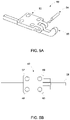
- FIG. 5A is a schematic representation of an exploded view of a lifting lever structure, according to a second embodiment for lifting computer components from a computer.
- FIG. 5B is a schematic, plan view of the lifting lever structure of FIG. 5A .
- FIG. 5C is a schematic, elevation view of the lifting lever structure of FIG. 5A .
- FIG. 5D is a schematic, right side view of the lifting lever structure of FIG. 5A .
- FIG. 6A is a schematic, perspective view of a GPU, including a plurality of PCIe cards contained therein, which are releasable by a combined operation of release hook and lifting lever.
- FIG. 6B is a schematic, enlarged view of the dotted line area 33 of FIG. 6A to show detail.
- FIG. 6C is a schematic, enlarged view of FIG. 6A to show detail of the release of the PCIe cards.
- FIG. 7A is a schematic, representation of a system for releasing a secured PCIe card in a GPU.
- FIG. 7B is a schematic representation of the release lever portion only of FIG. 7A .
- FIG. 7C is a schematic representation of the release lever lifting and releasing the PCIe card of FIG. 7A from a GPU.
- FIG. 7D is a schematic representation of the angular displacement of the release lever portion only in lifting and releasing the PCIe card of FIG. 7C from a GPU.
- FIG. 1 illustrates, in exploded view, the details of an exemplary release hook structure 10 in accordance with the present disclosure.
- FIG. 2A is a schematic, plan view of a release hook structure 10 , clearly illustrating the thumbscrews 16 , 17 that permit raising of the pivot claws 20 , 21 (not visible in FIG. 2A ).
- FIG. 2B is a schematic, elevation view of the release hook of FIG. 1 illustrating the position of arms 13 , 14 in a position below fixing element 15 .
- FIG. 2C is a schematic, left side view of the release hook of FIG. 1 , and illustrating the claw 20 , which begins the lifting of the card, as the thumbscrews 16 , 17 are lifted upwardly.
- FIG. 2D is a schematic, perspective view of release hook structure 10 .
- a release hook 12 (from FIG.
- a fixing element 15 is provided in order to mount the release hook 12 .
- One or more thumbscrews 16 , 17 is provided to move release hook 12 from a position holding a computer component to a chassis, tray, or other supporting structure of a computer.
- a series of screws 18 , 19 are used to secure fixing element 15 to release hook 12 .
- FIGS. 3A-3C illustrate the use of release hook 10 in the environment of PCIe cards in a GPU tray, although this same configuration and structure can be employed to release components other than PCIe cards.
- GPU tray 30 contains a series of PCIe cards 31 , 32 , etc.
- the release hook structure 10 In order to hold and release the PCIe cards, use is made of the release hook structure 10 .
- a rail 22 is provided.
- the rail 22 defines a plurality of openings or slots 26 , 27 , 28 , 29 , through which arms 13 , 14 , of the lifting hook structure 10 can extend. Arms 13 , 14 can extend through adjacent slots in rail 22 ( FIGS. 3B, 3C ).
- the rail 22 can retain and capture the arms 13 , 14 , especially if the arms 13 , 14 are each provided with a flange 23 , 24 , respectively.
- the release hook structure 10 can retain the PCIe cards in their required position when in their operative position. However, when it is desired to remove the PCIe cards, the thumbscrews 16 , 17 are pulled upwardly, as shown in FIG. 3C . This action in pulling thumbscrews 16 , 17 upwardly acts to rotate pivot claws 20 , 21 , thereby simultaneously releasing and lifting the PCIe card from GPU tray 30 .
- FIGS. 4A and 4B This action is shown schematically in FIGS. 4A and 4B .
- the initial upward movement on thumbscrews 16 , 17 gradually turns to rotational movement (as indicted by arrow 9 in FIG. 4B ), as the arms 13 , 14 interact with their respective slot 29 in the rail 22 .
- PCIe card 31 is positioned to contact precisely PCB 40 , as shown schematically in FIG. 4A .
- the arm 14 is rotated by lifting upon thumbscrew 17 .
- This action then pivots claw 21 upwardly as well, causing claw 21 to contact, and then lift flange 34 of PCIe card 31 , releasing and simultaneously lifting PCIe card 31 out of contact with PCB 40 .
- This action is capable of lifting PCIe card 31 over 6 mm, thereby permitting grasping and removal of PCIe card 31 from GPU tray 30 with a person's fingers.
- FIGS. 5A-5D illustrate a second embodiment of a lifting mechanism that can be used with, or in place of, the release hook lifting structure of FIG. 1 .
- FIG. 5A illustrates a lifting base 52 , defining several opening 57 , 58 , 59 , 60 to permit fasteners, such as screws (not shown) to pass through and secure the lifting base 52 to a support structure.
- the support structure could be the rail 22 (as shown in FIGS. 3B-3C ), or the release hook 12 (of FIG. 1 ).
- FIG. 5B is a schematic, plan view of FIG. 5A .
- Bosses 61 , 62 define an opening passing through bosses 61 , 62 to receive a shaft 54 to secure release lever 56 to lifting base 52 .
- FIG. 5C which is a schematic, elevation view of FIG. 5A , clearly shows the pivoting connection between release lever 56 and lifting base 52 .
- FIG. 5D is a schematic, right side view of FIG. 5A .
- Release lever 56 provides an alternative lifting action to that of lifting hook 12 .
- FIG. 5A shows a schematically illustrated a PCIe card release lever 50 , which comprises a PCIe card release base 52 . Pivotably coupled to PCIe card release base 52 is a PCIe release lever 56 , which terminates in a nose 67 to contact the PCIe card.
- a shaft 54 acts as the coupling element for PCIe release lever 56 and PCIe release base 52 , and also permits pivoting of PCIe card release lever 56 relative to PCIe release base 52 .
- PCIe card release base 52 defines a plurality of apertures 57 , 58 , 59 60 for the purpose of receiving fasteners, such as screws or rivets, to secure the PCIe card release base to the tray or chassis of a computer. Further views of each of the components of FIG. 5A can be seen in FIGS. 5B, 5C, and 5D .
- PCIe release lever 56 Operation of PCIe release lever 56 will now be described in connection with FIGS. 6A-6C .
- GPU tray 30 contains a plurality of PCIe cards 31 , 32 , etc.
- PCIe card release lever 50 is mounted to the tray 30 by means of fasteners (not shown).
- the end of release lever 56 is displaced downwardly by pushing against the protruding end 65 of release lever 56 , as shown by arrow 64 in FIG. 6B .
- the protruding end 65 of release lever 56 will rotate, as shown by arrow 66 in FIG. 6C .
- the opposite end 67 (hidden in FIG. 6C , but illustrated in FIG. 5C ) of release lever 56 will push upwardly against PCIe card 32 , and lift it out of its position from within tray 30 , as shown by arrow 68 in FIG. 6C .
- release lever 56 can be better understood in connection with the schematic representation of FIGS. 7A-7D .
- PCIe card 32 is in position against PCB 40 , as shown in FIG. 7B .
- a downward force is exerted in the direction of arrow 64 , and against protruding end 65 of release lever 56 .
- release lever 56 is pivotably mounted about shaft 54 , the downward force exerted against protruding end 65 of release lever 56 translates to a rotational motion a about shaft 54 .
- This upwardly lifting force displaces PCIe card 32 away from the PCB 40 .
- the rotational motion a can be up to and include an angle of about 35°. This can result in a lifting of PCIe card 32 in an amount of more than 6 mm.
- This lifting of PCIe card 32 (shown by arrow 70 in FIGS. 7C and 7D ) can be selected so that it is sufficient to permit an operator to grasp PCIe card 32 , and complete the removal of the PCIe card 32 or other computer component from the tray 30 .
- the process can be repeated for the other PCIe cards e.g., PCIe card 31 , within tray 30 by the use of levers 560 , 561 , 562 ( FIG. 6C ), respectively.
Landscapes
- Engineering & Computer Science (AREA)
- Theoretical Computer Science (AREA)
- General Engineering & Computer Science (AREA)
- Computer Hardware Design (AREA)
- Physics & Mathematics (AREA)
- Power Engineering (AREA)
- Human Computer Interaction (AREA)
- General Physics & Mathematics (AREA)
- Microelectronics & Electronic Packaging (AREA)
- Manufacturing & Machinery (AREA)
- Electromagnetism (AREA)
- Mounting Of Printed Circuit Boards And The Like (AREA)
- Casings For Electric Apparatus (AREA)
Abstract
Description
Claims (8)
Priority Applications (5)
| Application Number | Priority Date | Filing Date | Title |
|---|---|---|---|
| US16/047,390 US11297750B2 (en) | 2018-03-22 | 2018-07-27 | Mechanism to release cards and other components from computer |
| TW107132562A TWI682264B (en) | 2018-03-22 | 2018-09-17 | Releasing device and releasing combination |
| CN201811146592.2A CN110297527A (en) | 2018-03-22 | 2018-09-29 | Release device and release combination |
| EP18202964.5A EP3543826B1 (en) | 2018-03-22 | 2018-10-26 | Mechanism to release cards and other components from computer |
| JP2018221163A JP6719534B2 (en) | 2018-03-22 | 2018-11-27 | Mechanism for removing cards and other parts from the computer |
Applications Claiming Priority (2)
| Application Number | Priority Date | Filing Date | Title |
|---|---|---|---|
| US201862646527P | 2018-03-22 | 2018-03-22 | |
| US16/047,390 US11297750B2 (en) | 2018-03-22 | 2018-07-27 | Mechanism to release cards and other components from computer |
Publications (2)
| Publication Number | Publication Date |
|---|---|
| US20190294219A1 US20190294219A1 (en) | 2019-09-26 |
| US11297750B2 true US11297750B2 (en) | 2022-04-05 |
Family
ID=64051459
Family Applications (1)
| Application Number | Title | Priority Date | Filing Date |
|---|---|---|---|
| US16/047,390 Active 2039-10-24 US11297750B2 (en) | 2018-03-22 | 2018-07-27 | Mechanism to release cards and other components from computer |
Country Status (5)
| Country | Link |
|---|---|
| US (1) | US11297750B2 (en) |
| EP (1) | EP3543826B1 (en) |
| JP (1) | JP6719534B2 (en) |
| CN (1) | CN110297527A (en) |
| TW (1) | TWI682264B (en) |
Families Citing this family (2)
| Publication number | Priority date | Publication date | Assignee | Title |
|---|---|---|---|---|
| CN112346521B (en) * | 2019-08-08 | 2024-08-02 | 纬联电子科技(中山)有限公司 | Expansion module assembling frame and electronic device |
| US11395431B2 (en) | 2020-06-26 | 2022-07-19 | Hewlett Packard Enterprise Development Lp | Compute node having a chassis with front installed GPU tray |
Citations (21)
| Publication number | Priority date | Publication date | Assignee | Title |
|---|---|---|---|---|
| US4894910A (en) * | 1988-08-29 | 1990-01-23 | Gte Communicaton Systems, Inc. | Pin grid array removal tool |
| US6003689A (en) | 1998-03-18 | 1999-12-21 | 3Com Corporation | PCB ejector cage assembly |
| US6018867A (en) * | 1997-10-02 | 2000-02-01 | Micron Electronics, Inc. | Integrated circuit cartridge extracting tool |
| JP2002237689A (en) | 2001-02-08 | 2002-08-23 | Hitachi Kokusai Electric Inc | Board removal structure |
| TW543814U (en) | 2002-02-06 | 2003-07-21 | Chenming Mold Ind Corp | Fastening structure for locking interface card |
| TW584222U (en) | 2002-07-25 | 2004-04-11 | Uniwill Comp Corp | Detaching device for heat-dissipating apparatus |
| US20050181662A1 (en) * | 2004-02-16 | 2005-08-18 | Frank Greiser | Printed circuit board module and disconnect bow |
| US20060215373A1 (en) * | 2005-03-10 | 2006-09-28 | Schroff Gmbh | Device for levering in and levering out a plug-in unit |
| US20070082513A1 (en) * | 2005-09-29 | 2007-04-12 | Tieyu Zheng | Self-balanced dual L-shaped socket |
| JP2008047746A (en) | 2006-08-18 | 2008-02-28 | Fujitsu Ltd | PIU insertion / extraction mechanism for electronic devices |
| CN101344802A (en) | 2007-07-15 | 2009-01-14 | 史秋伟 | Easy pulling structure improvement of interface card |
| JP2009265781A (en) * | 2008-04-23 | 2009-11-12 | Funai Electric Co Ltd | Lid locking device for card insertion port |
| US20100244996A1 (en) * | 2009-03-24 | 2010-09-30 | Hsin-Meng Kuo | Signal transmission device with single output configuration and related motherboard |
| US20110277967A1 (en) * | 2007-04-16 | 2011-11-17 | Stephen Samuel Fried | Liquid cooled condensers for loop heat pipe like enclosure cooling |
| US20120039044A1 (en) * | 2010-08-12 | 2012-02-16 | Hon Hai Precision Industry Co., Ltd. | Electronic device and heat dissipation apparatus of the same |
| CN103105909A (en) | 2011-11-14 | 2013-05-15 | 鸿富锦精密工业(深圳)有限公司 | Servers with expansion card modules |
| CN103823510A (en) | 2012-11-16 | 2014-05-28 | 英业达科技有限公司 | Electronic device and fixing structure thereof |
| US20160018859A1 (en) | 2014-07-16 | 2016-01-21 | Wistron Corporation | Fixing mechanism and electronic device capable of assembling and disassembling an expansion card module |
| US20160219745A1 (en) * | 2015-01-28 | 2016-07-28 | International Business Machines Corporation | Latch and spring assembly |
| US20160278231A1 (en) * | 2013-11-01 | 2016-09-22 | Hewlett Packard Enterprise Development Lp | Top loading cartridge |
| US20170125943A1 (en) | 2015-10-30 | 2017-05-04 | Thales | Locking and extraction device for an electrical connector |
-
2018
- 2018-07-27 US US16/047,390 patent/US11297750B2/en active Active
- 2018-09-17 TW TW107132562A patent/TWI682264B/en active
- 2018-09-29 CN CN201811146592.2A patent/CN110297527A/en active Pending
- 2018-10-26 EP EP18202964.5A patent/EP3543826B1/en active Active
- 2018-11-27 JP JP2018221163A patent/JP6719534B2/en active Active
Patent Citations (24)
| Publication number | Priority date | Publication date | Assignee | Title |
|---|---|---|---|---|
| US4894910A (en) * | 1988-08-29 | 1990-01-23 | Gte Communicaton Systems, Inc. | Pin grid array removal tool |
| US6018867A (en) * | 1997-10-02 | 2000-02-01 | Micron Electronics, Inc. | Integrated circuit cartridge extracting tool |
| US6003689A (en) | 1998-03-18 | 1999-12-21 | 3Com Corporation | PCB ejector cage assembly |
| JP2002237689A (en) | 2001-02-08 | 2002-08-23 | Hitachi Kokusai Electric Inc | Board removal structure |
| TW543814U (en) | 2002-02-06 | 2003-07-21 | Chenming Mold Ind Corp | Fastening structure for locking interface card |
| TW584222U (en) | 2002-07-25 | 2004-04-11 | Uniwill Comp Corp | Detaching device for heat-dissipating apparatus |
| US20050181662A1 (en) * | 2004-02-16 | 2005-08-18 | Frank Greiser | Printed circuit board module and disconnect bow |
| US20060215373A1 (en) * | 2005-03-10 | 2006-09-28 | Schroff Gmbh | Device for levering in and levering out a plug-in unit |
| US20070082513A1 (en) * | 2005-09-29 | 2007-04-12 | Tieyu Zheng | Self-balanced dual L-shaped socket |
| JP2008047746A (en) | 2006-08-18 | 2008-02-28 | Fujitsu Ltd | PIU insertion / extraction mechanism for electronic devices |
| US20110277967A1 (en) * | 2007-04-16 | 2011-11-17 | Stephen Samuel Fried | Liquid cooled condensers for loop heat pipe like enclosure cooling |
| CN101344802A (en) | 2007-07-15 | 2009-01-14 | 史秋伟 | Easy pulling structure improvement of interface card |
| JP2009265781A (en) * | 2008-04-23 | 2009-11-12 | Funai Electric Co Ltd | Lid locking device for card insertion port |
| US20100244996A1 (en) * | 2009-03-24 | 2010-09-30 | Hsin-Meng Kuo | Signal transmission device with single output configuration and related motherboard |
| US20120039044A1 (en) * | 2010-08-12 | 2012-02-16 | Hon Hai Precision Industry Co., Ltd. | Electronic device and heat dissipation apparatus of the same |
| CN103105909A (en) | 2011-11-14 | 2013-05-15 | 鸿富锦精密工业(深圳)有限公司 | Servers with expansion card modules |
| US20130120928A1 (en) | 2011-11-14 | 2013-05-16 | Hon Hai Precision Industry Co., Ltd. | Server with expansion card |
| CN103823510A (en) | 2012-11-16 | 2014-05-28 | 英业达科技有限公司 | Electronic device and fixing structure thereof |
| US20160278231A1 (en) * | 2013-11-01 | 2016-09-22 | Hewlett Packard Enterprise Development Lp | Top loading cartridge |
| US20160018859A1 (en) | 2014-07-16 | 2016-01-21 | Wistron Corporation | Fixing mechanism and electronic device capable of assembling and disassembling an expansion card module |
| CN105302234A (en) | 2014-07-16 | 2016-02-03 | 纬创资通股份有限公司 | Fixing mechanism capable of being used for disassembling and assembling expansion card module and electronic device |
| US20160219745A1 (en) * | 2015-01-28 | 2016-07-28 | International Business Machines Corporation | Latch and spring assembly |
| US20170125943A1 (en) | 2015-10-30 | 2017-05-04 | Thales | Locking and extraction device for an electrical connector |
| CN107046212A (en) | 2015-10-30 | 2017-08-15 | 泰勒斯公司 | Locking and extraction equipment for electric connector |
Non-Patent Citations (5)
| Title |
|---|
| CN Office Action for Application No. 2018-11146592.2, dated Nov. 4, 2020, w/ Second Office Action Summary. |
| CN Search Report for Application No. 2018-11146592.2, dated Nov. 4, 2020, w/ Second Office Action. |
| Extended European Search Report for EP Application No. 18202964.5, dated May 17, 2019. |
| JP Office Action for Application No. 2018-221163, dated Dec. 24, 2019, w/ First Office Action Summary. |
| TW Office Action for Application No. 107132562, dated Jul. 8, 2019, w/ First Office Action Summary. |
Also Published As
| Publication number | Publication date |
|---|---|
| US20190294219A1 (en) | 2019-09-26 |
| CN110297527A (en) | 2019-10-01 |
| TWI682264B (en) | 2020-01-11 |
| TW201941016A (en) | 2019-10-16 |
| JP6719534B2 (en) | 2020-07-08 |
| EP3543826A1 (en) | 2019-09-25 |
| EP3543826B1 (en) | 2025-01-22 |
| JP2019169123A (en) | 2019-10-03 |
Similar Documents
| Publication | Publication Date | Title |
|---|---|---|
| US11297750B2 (en) | Mechanism to release cards and other components from computer | |
| CN101055773B (en) | Movable extension assembly for a mounting system | |
| JP6857679B2 (en) | Add-on card locking mechanism | |
| CN105302234A (en) | Fixing mechanism capable of being used for disassembling and assembling expansion card module and electronic device | |
| US20090002960A1 (en) | Apparatus for retaining a computer card | |
| CN105867553B (en) | Hard disk fixing device | |
| US20060198115A1 (en) | Mounting apparatus for expansion card | |
| US7975972B1 (en) | Convertible apparatus for attaching an article to a wall | |
| US8092106B2 (en) | Keyboard with hook for hanging keyboard on another object | |
| TWM252059U (en) | Retention device for power supply | |
| EP2992399A1 (en) | Foot support assembly for cantilevered touch screen | |
| US20080237557A1 (en) | Door and Board Lifting Device | |
| CN107844168A (en) | Mainboard assembly and its bayonet unit | |
| CN105828563B (en) | The fixture construction of the printed circuit board of electronic device unit | |
| US7558055B2 (en) | Retaining apparatus for expansion card | |
| US9098253B2 (en) | Information handling system tool-less daughter card retainer and latch | |
| TWI222554B (en) | Engagement device | |
| SE518693C2 (en) | Packaging for edge tools | |
| TWM314361U (en) | Latch design of a notebook computer | |
| CN205091670U (en) | Computer casing, computer host with same and computer system | |
| JP2003181770A (en) | Hand tools for cage nuts | |
| JP2010047133A (en) | Detachable caster device | |
| JP2003181087A (en) | Hinge unit of game machine | |
| US20190030542A1 (en) | Device to assist in manual transfer of pipette tips | |
| EP2168779A2 (en) | Document holder |
Legal Events
| Date | Code | Title | Description |
|---|---|---|---|
| AS | Assignment |
Owner name: QUANTA COMPUTER INC., TAIWAN Free format text: ASSIGNMENT OF ASSIGNORS INTEREST;ASSIGNORS:TSORNG, YAW-TZORNG;CHANG, CHUN;WANG, JHIH-HONG;REEL/FRAME:046486/0622 Effective date: 20180718 |
|
| FEPP | Fee payment procedure |
Free format text: ENTITY STATUS SET TO UNDISCOUNTED (ORIGINAL EVENT CODE: BIG.); ENTITY STATUS OF PATENT OWNER: LARGE ENTITY |
|
| STPP | Information on status: patent application and granting procedure in general |
Free format text: NON FINAL ACTION MAILED |
|
| STPP | Information on status: patent application and granting procedure in general |
Free format text: RESPONSE TO NON-FINAL OFFICE ACTION ENTERED AND FORWARDED TO EXAMINER |
|
| STPP | Information on status: patent application and granting procedure in general |
Free format text: FINAL REJECTION MAILED |
|
| STPP | Information on status: patent application and granting procedure in general |
Free format text: RESPONSE AFTER FINAL ACTION FORWARDED TO EXAMINER |
|
| STPP | Information on status: patent application and granting procedure in general |
Free format text: ADVISORY ACTION MAILED |
|
| STPP | Information on status: patent application and granting procedure in general |
Free format text: DOCKETED NEW CASE - READY FOR EXAMINATION |
|
| STPP | Information on status: patent application and granting procedure in general |
Free format text: NON FINAL ACTION MAILED |
|
| STPP | Information on status: patent application and granting procedure in general |
Free format text: RESPONSE TO NON-FINAL OFFICE ACTION ENTERED AND FORWARDED TO EXAMINER |
|
| STPP | Information on status: patent application and granting procedure in general |
Free format text: NOTICE OF ALLOWANCE MAILED -- APPLICATION RECEIVED IN OFFICE OF PUBLICATIONS |
|
| STPP | Information on status: patent application and granting procedure in general |
Free format text: PUBLICATIONS -- ISSUE FEE PAYMENT VERIFIED |
|
| STCF | Information on status: patent grant |
Free format text: PATENTED CASE |
|
| MAFP | Maintenance fee payment |
Free format text: PAYMENT OF MAINTENANCE FEE, 4TH YEAR, LARGE ENTITY (ORIGINAL EVENT CODE: M1551); ENTITY STATUS OF PATENT OWNER: LARGE ENTITY Year of fee payment: 4 |