US11296512B2 - Power controller apparatus for power system including customer facilities with power storage apparatuses - Google Patents

Power controller apparatus for power system including customer facilities with power storage apparatuses Download PDF

Info

Publication number
US11296512B2
US11296512B2 US17/272,072 US201917272072A US11296512B2 US 11296512 B2 US11296512 B2 US 11296512B2 US 201917272072 A US201917272072 A US 201917272072A US 11296512 B2 US11296512 B2 US 11296512B2
Authority
US
United States
Prior art keywords
power
power storage
charging
storage apparatuses
discharging
Prior art date
Legal status (The legal status is an assumption and is not a legal conclusion. Google has not performed a legal analysis and makes no representation as to the accuracy of the status listed.)
Active
Application number
US17/272,072
Other versions
US20210328433A1 (en
Inventor
Junichi Kanou
Akira Minegishi
Tetsuyoshi Ogura
Current Assignee (The listed assignees may be inaccurate. Google has not performed a legal analysis and makes no representation or warranty as to the accuracy of the list.)
Panasonic Intellectual Property Management Co Ltd
Original Assignee
Panasonic Intellectual Property Management Co Ltd
Priority date (The priority date is an assumption and is not a legal conclusion. Google has not performed a legal analysis and makes no representation as to the accuracy of the date listed.)
Filing date
Publication date
Application filed by Panasonic Intellectual Property Management Co Ltd filed Critical Panasonic Intellectual Property Management Co Ltd
Assigned to PANASONIC INTELLECTUAL PROPERTY MANAGEMENT CO., LTD. reassignment PANASONIC INTELLECTUAL PROPERTY MANAGEMENT CO., LTD. ASSIGNMENT OF ASSIGNORS INTEREST (SEE DOCUMENT FOR DETAILS). Assignors: MINEGISHI, AKIRA, KANOU, Junichi, OGURA, TETSUYOSHI
Publication of US20210328433A1 publication Critical patent/US20210328433A1/en
Application granted granted Critical
Publication of US11296512B2 publication Critical patent/US11296512B2/en
Active legal-status Critical Current
Anticipated expiration legal-status Critical

Links

Images

Classifications

    • HELECTRICITY
    • H02GENERATION; CONVERSION OR DISTRIBUTION OF ELECTRIC POWER
    • H02JCIRCUIT ARRANGEMENTS OR SYSTEMS FOR SUPPLYING OR DISTRIBUTING ELECTRIC POWER; SYSTEMS FOR STORING ELECTRIC ENERGY
    • H02J3/00Circuit arrangements for ac mains or ac distribution networks
    • H02J3/12Circuit arrangements for ac mains or ac distribution networks for adjusting voltage in ac networks by changing a characteristic of the network load
    • H02J3/14Circuit arrangements for ac mains or ac distribution networks for adjusting voltage in ac networks by changing a characteristic of the network load by switching loads on to, or off from, network, e.g. progressively balanced loading
    • HELECTRICITY
    • H02GENERATION; CONVERSION OR DISTRIBUTION OF ELECTRIC POWER
    • H02JCIRCUIT ARRANGEMENTS OR SYSTEMS FOR SUPPLYING OR DISTRIBUTING ELECTRIC POWER; SYSTEMS FOR STORING ELECTRIC ENERGY
    • H02J3/00Circuit arrangements for ac mains or ac distribution networks
    • H02J3/003Load forecast, e.g. methods or systems for forecasting future load demand
    • HELECTRICITY
    • H02GENERATION; CONVERSION OR DISTRIBUTION OF ELECTRIC POWER
    • H02JCIRCUIT ARRANGEMENTS OR SYSTEMS FOR SUPPLYING OR DISTRIBUTING ELECTRIC POWER; SYSTEMS FOR STORING ELECTRIC ENERGY
    • H02J3/00Circuit arrangements for ac mains or ac distribution networks
    • H02J3/004Generation forecast, e.g. methods or systems for forecasting future energy generation
    • HELECTRICITY
    • H02GENERATION; CONVERSION OR DISTRIBUTION OF ELECTRIC POWER
    • H02JCIRCUIT ARRANGEMENTS OR SYSTEMS FOR SUPPLYING OR DISTRIBUTING ELECTRIC POWER; SYSTEMS FOR STORING ELECTRIC ENERGY
    • H02J3/00Circuit arrangements for ac mains or ac distribution networks
    • H02J3/28Arrangements for balancing of the load in a network by storage of energy
    • H02J3/32Arrangements for balancing of the load in a network by storage of energy using batteries with converting means
    • HELECTRICITY
    • H02GENERATION; CONVERSION OR DISTRIBUTION OF ELECTRIC POWER
    • H02JCIRCUIT ARRANGEMENTS OR SYSTEMS FOR SUPPLYING OR DISTRIBUTING ELECTRIC POWER; SYSTEMS FOR STORING ELECTRIC ENERGY
    • H02J7/00Circuit arrangements for charging or depolarising batteries or for supplying loads from batteries
    • H02J7/0013Circuit arrangements for charging or depolarising batteries or for supplying loads from batteries acting upon several batteries simultaneously or sequentially
    • HELECTRICITY
    • H02GENERATION; CONVERSION OR DISTRIBUTION OF ELECTRIC POWER
    • H02JCIRCUIT ARRANGEMENTS OR SYSTEMS FOR SUPPLYING OR DISTRIBUTING ELECTRIC POWER; SYSTEMS FOR STORING ELECTRIC ENERGY
    • H02J7/00Circuit arrangements for charging or depolarising batteries or for supplying loads from batteries
    • H02J7/0047Circuit arrangements for charging or depolarising batteries or for supplying loads from batteries with monitoring or indicating devices or circuits
    • H02J7/0048Detection of remaining charge capacity or state of charge [SOC]
    • HELECTRICITY
    • H02GENERATION; CONVERSION OR DISTRIBUTION OF ELECTRIC POWER
    • H02JCIRCUIT ARRANGEMENTS OR SYSTEMS FOR SUPPLYING OR DISTRIBUTING ELECTRIC POWER; SYSTEMS FOR STORING ELECTRIC ENERGY
    • H02J7/00Circuit arrangements for charging or depolarising batteries or for supplying loads from batteries
    • H02J7/0047Circuit arrangements for charging or depolarising batteries or for supplying loads from batteries with monitoring or indicating devices or circuits
    • H02J7/005Detection of state of health [SOH]
    • HELECTRICITY
    • H02GENERATION; CONVERSION OR DISTRIBUTION OF ELECTRIC POWER
    • H02JCIRCUIT ARRANGEMENTS OR SYSTEMS FOR SUPPLYING OR DISTRIBUTING ELECTRIC POWER; SYSTEMS FOR STORING ELECTRIC ENERGY
    • H02J7/00Circuit arrangements for charging or depolarising batteries or for supplying loads from batteries
    • H02J7/007Regulation of charging or discharging current or voltage
    • H02J7/00712Regulation of charging or discharging current or voltage the cycle being controlled or terminated in response to electric parameters
    • HELECTRICITY
    • H02GENERATION; CONVERSION OR DISTRIBUTION OF ELECTRIC POWER
    • H02JCIRCUIT ARRANGEMENTS OR SYSTEMS FOR SUPPLYING OR DISTRIBUTING ELECTRIC POWER; SYSTEMS FOR STORING ELECTRIC ENERGY
    • H02J7/00Circuit arrangements for charging or depolarising batteries or for supplying loads from batteries
    • H02J7/007Regulation of charging or discharging current or voltage
    • H02J7/007188Regulation of charging or discharging current or voltage the charge cycle being controlled or terminated in response to non-electric parameters
    • HELECTRICITY
    • H02GENERATION; CONVERSION OR DISTRIBUTION OF ELECTRIC POWER
    • H02JCIRCUIT ARRANGEMENTS OR SYSTEMS FOR SUPPLYING OR DISTRIBUTING ELECTRIC POWER; SYSTEMS FOR STORING ELECTRIC ENERGY
    • H02J2310/00The network for supplying or distributing electric power characterised by its spatial reach or by the load
    • H02J2310/50The network for supplying or distributing electric power characterised by its spatial reach or by the load for selectively controlling the operation of the loads
    • H02J2310/56The network for supplying or distributing electric power characterised by its spatial reach or by the load for selectively controlling the operation of the loads characterised by the condition upon which the selective controlling is based
    • H02J2310/62The condition being non-electrical, e.g. temperature
    • H02J2310/64The condition being economic, e.g. tariff based load management
    • YGENERAL TAGGING OF NEW TECHNOLOGICAL DEVELOPMENTS; GENERAL TAGGING OF CROSS-SECTIONAL TECHNOLOGIES SPANNING OVER SEVERAL SECTIONS OF THE IPC; TECHNICAL SUBJECTS COVERED BY FORMER USPC CROSS-REFERENCE ART COLLECTIONS [XRACs] AND DIGESTS
    • Y02TECHNOLOGIES OR APPLICATIONS FOR MITIGATION OR ADAPTATION AGAINST CLIMATE CHANGE
    • Y02BCLIMATE CHANGE MITIGATION TECHNOLOGIES RELATED TO BUILDINGS, e.g. HOUSING, HOUSE APPLIANCES OR RELATED END-USER APPLICATIONS
    • Y02B70/00Technologies for an efficient end-user side electric power management and consumption
    • Y02B70/30Systems integrating technologies related to power network operation and communication or information technologies for improving the carbon footprint of the management of residential or tertiary loads, i.e. smart grids as climate change mitigation technology in the buildings sector, including also the last stages of power distribution and the control, monitoring or operating management systems at local level
    • Y02B70/3225Demand response systems, e.g. load shedding, peak shaving
    • YGENERAL TAGGING OF NEW TECHNOLOGICAL DEVELOPMENTS; GENERAL TAGGING OF CROSS-SECTIONAL TECHNOLOGIES SPANNING OVER SEVERAL SECTIONS OF THE IPC; TECHNICAL SUBJECTS COVERED BY FORMER USPC CROSS-REFERENCE ART COLLECTIONS [XRACs] AND DIGESTS
    • Y04INFORMATION OR COMMUNICATION TECHNOLOGIES HAVING AN IMPACT ON OTHER TECHNOLOGY AREAS
    • Y04SSYSTEMS INTEGRATING TECHNOLOGIES RELATED TO POWER NETWORK OPERATION, COMMUNICATION OR INFORMATION TECHNOLOGIES FOR IMPROVING THE ELECTRICAL POWER GENERATION, TRANSMISSION, DISTRIBUTION, MANAGEMENT OR USAGE, i.e. SMART GRIDS
    • Y04S20/00Management or operation of end-user stationary applications or the last stages of power distribution; Controlling, monitoring or operating thereof
    • Y04S20/20End-user application control systems
    • Y04S20/222Demand response systems, e.g. load shedding, peak shaving
    • YGENERAL TAGGING OF NEW TECHNOLOGICAL DEVELOPMENTS; GENERAL TAGGING OF CROSS-SECTIONAL TECHNOLOGIES SPANNING OVER SEVERAL SECTIONS OF THE IPC; TECHNICAL SUBJECTS COVERED BY FORMER USPC CROSS-REFERENCE ART COLLECTIONS [XRACs] AND DIGESTS
    • Y04INFORMATION OR COMMUNICATION TECHNOLOGIES HAVING AN IMPACT ON OTHER TECHNOLOGY AREAS
    • Y04SSYSTEMS INTEGRATING TECHNOLOGIES RELATED TO POWER NETWORK OPERATION, COMMUNICATION OR INFORMATION TECHNOLOGIES FOR IMPROVING THE ELECTRICAL POWER GENERATION, TRANSMISSION, DISTRIBUTION, MANAGEMENT OR USAGE, i.e. SMART GRIDS
    • Y04S50/00Market activities related to the operation of systems integrating technologies related to power network operation or related to communication or information technologies
    • Y04S50/10Energy trading, including energy flowing from end-user application to grid

Definitions

  • the present disclosure relates to a power controller apparatus for a power system including a plurality of customer facilities.
  • the present disclosure also relates to a power system including such a power controller apparatus and customer facilities.
  • Some customers of commercial power use a customer facility provided with a power storage apparatus and/or a power generator apparatus, as well as various load apparatuses consuming power.
  • a power storage apparatus By using the power storage apparatus, it is possible to reduce a peak of power consumed by the load apparatuses of the customer facility.
  • the power generator apparatus By using the power generator apparatus, it is possible to reduce power consumption and price of the commercial power.
  • Patent Document 1 it has been proposed to transmit and receive power among a plurality of customer facilities of a power system, the plurality of customer facilities each provided with a power storage apparatus, and share the power storage apparatuses among the plurality of customer facilities. By sharing the power storage apparatuses among the plurality of customer facilities, it is possible to achieve a sufficiently large total capacity even if each of the power storage apparatuses has a reduced capacity.
  • PATENT DOCUMENT 1 Japanese Patent No. JP 6163040 B
  • the number of charging and discharging cycles of each of the power storage apparatuses becomes larger than that of the case without transmitting and receiving power, and therefore, the power storage apparatuses are more likely to degrade.
  • some of a plurality of power supply apparatuses provided at the facilities are selected to be suspended at predetermined intervals. This extends the lifetime of the power supply apparatuses of the facilities.
  • tasks of the suspended power supply apparatuses should be done by the other power supply apparatuses. Accordingly, the number of charging and discharging cycles of each of the power storage apparatuses can not be reduced, and therefore, the power storage apparatuses are likely to degrade. In addition, losses may occur in paths for transmitting and receiving power.
  • An object of the present disclosure is to provide a power controller apparatus capable of controlling a plurality of customer facilities so that their power storage apparatuses are less likely to degrade, even when transmitting and receiving power among the plurality of customer facilities and sharing the power storage apparatuses among the plurality of customer facilities.
  • Another object of the present disclosure is to provide a power system including such a power controller apparatus and customer facilities.
  • a power controller apparatus for a power system including a plurality of customer facilities connected to each other via a power network connected to a power supply facility.
  • the plurality of customer facilities are provided with load apparatuses, respectively, and at least two of the plurality of customer facilities are further provided with power storage apparatuses, respectively.
  • the power controller apparatus is configured to predict demand power of each of the load apparatuses of the customer facilities for a unit time interval.
  • the power controller apparatus is further configured to determine a reference capacity of each of the power storage apparatuses based on the demand power, the reference capacity indicating a capacity of each of the power storage apparatuses necessary to maintain power received by each of the customer facilities from the power supply facility at a first threshold or lower, under an assumption that power is not transmitted and received among the customer facilities.
  • the power controller apparatus is further configured to determine an actual capacity of each of the power storage apparatuses based on the demand power, the actual capacity indicating a capacity of each of the power storage apparatuses necessary to maintain the power received by each of the customer facilities from the power supply facility at the first threshold or lower, under an assumption that power is transmitted and received among the customer facilities.
  • the power controller apparatus is further configured to calculate a first characteristic value of each of the power storage apparatuses based on the demand power, the first characteristic value being associated with a degree of degradation of each of the power storage apparatuses for the unit time interval, under an assumption that power is not transmitted and received among the customer facilities, and that charging and discharging of each of the power storage apparatuses having the reference capacity are controlled so as to maintain the power received by each of the customer facilities from the power supply facility at the first threshold or lower.
  • the power controller apparatus is further configured to calculate a second characteristic value of each of the power storage apparatuses based on the demand power, the second characteristic value being associated with the degree of degradation of each of the power storage apparatuses for the unit time interval, under an assumption that power is transmitted and received among the customer facilities, and that charging and discharging of each of the power storage apparatuses having the actual capacity are controlled so as to maintain the power received by each of the customer facilities from the power supply facility at the first threshold or lower, and determine a charging and discharging plan of the power storage apparatuses for the unit time interval so as to minimize an objective function indicating a degree of degradation from the first characteristic value to the second characteristic value.
  • the power controller apparatus is further configured to control charging and discharging of each of the power storage apparatuses having the actual capacity in accordance with the charging and discharging plan.
  • the power controller apparatus can control the plurality of customer facilities so that their power storage apparatuses are less likely to degrade, even when transmitting and receiving power among the plurality of customer facilities and sharing the power storage apparatuses among the plurality of customer facilities.
  • FIG. 1 is a block diagram of a configuration of a power system according to a first embodiment.
  • FIG. 2 is a block diagram of a configuration of a power controller apparatus 4 of FIG. 1 .
  • FIG. 3 is a flowchart showing a first power control process executed by the power controller apparatus 4 of FIG. 1 .
  • FIG. 4 is a subroutine showing a power prediction process of steps S 1 , S 5 in FIG. 3 .
  • FIG. 5 is a subroutine showing a reference capacity determination process of step S 2 in FIG. 3 .
  • FIG. 6 is a subroutine showing an actual capacity determination process of step S 3 in FIG. 3 .
  • FIG. 7 is a subroutine showing a characteristic value determination process of step S 6 in FIG. 3 .
  • FIG. 8 is a subroutine showing a charging and discharging plan determination process of step S 7 in FIG. 3 .
  • FIG. 9 is a set of graphs showing exemplary temporal variations in demand power, buying and selling power, generated power, and charging and discharging power of each of the customer facilities 1 of FIG. 1 , in a case without transmitting and receiving power among the customer facilities 1 .
  • FIG. 10 is a graph showing exemplary temporal variations in charged electric energy of each of power storage apparatuses 13 of the customer facilities 1 of FIG. 1 , in the case without transmitting and receiving power among the customer facilities 1 .
  • FIG. 11 is a graph for explaining determination of a reference capacity of the power storage apparatus 13 in step S 2 of FIG. 3 .
  • FIG. 12 is a set of graphs showing exemplary temporal variations in demand power, buying and selling power, generated power, and charging and discharging power of each of the customer facilities 1 of FIG. 1 , in a case with transmitting and receiving power among the customer facilities 1 and without constraints on charging and discharging of the power storage apparatuses 13 .
  • FIG. 13 is a graph showing exemplary temporal variations in charged electric energy of each of the power storage apparatuses 13 of the customer facilities 1 of FIG. 1 , in the case with transmitting and receiving power among the customer facilities 1 and without constraints on charging and discharging of the power storage apparatuses 13 .
  • FIG. 14 is a set of graphs showing exemplary temporal variations in demand power, buying and selling power, generated power, and charging and discharging power of each of the customer facilities 1 of FIG. 1 , in a case with transmitting and receiving power among the customer facilities 1 and with constraints on charging and discharging of the power storage apparatuses 13 .
  • FIG. 15 is a graph showing exemplary temporal variations in charged electric energy of each of the power storage apparatuses 13 of the customer facilities 1 of FIG. 1 , in the case with transmitting and receiving power among the customer facilities 1 and with constraints on charging and discharging of the power storage apparatuses 13 .
  • FIG. 16 is a graph showing exemplary degradation rates of the power storage apparatuses 13 in the case without transmitting and receiving power among the customer facilities 1 of FIG. 1 , in the case with transmitting and receiving power among the customer facilities 1 of FIG. 1 and without constraints on charging and discharging of the power storage apparatuses 13 , and in the case with transmitting and receiving power among the customer facilities 1 of FIG. 1 and with constraints on charging and discharging of the power storage apparatuses 13 .
  • FIG. 17 is a graph showing exemplary temporal variations in total buying and selling power and total charging and discharging power of the customer facilities 1 of FIG. 1 , in the case with transmitting and receiving power among the customer facilities 1 and without constraints on charging and discharging of the power storage apparatuses 13 .
  • FIG. 18 is a graph showing exemplary temporal variations in total buying and selling power and total charging and discharging power of the customer facilities 1 of FIG. 1 , in the case with transmitting and receiving power among the customer facilities 1 and with constraints on charging and discharging of the power storage apparatuses 13 .
  • FIG. 19 is a flowchart showing a second power control process executed by the power controller apparatus 4 of FIG. 1 .
  • FIG. 20 is a subroutine showing a power prediction process of step S 102 in FIG. 19 .
  • FIG. 21 is a subroutine showing a reference capacity determination process of step S 103 in FIG. 19 .
  • FIG. 22 is a subroutine showing an actual capacity determination process of step S 104 in FIG. 19 .
  • FIG. 23 is a graph for explaining an objective function f a used by a power system according to a first modified embodiment of the first embodiment.
  • FIG. 24 is a graph for explaining objective functions f b , f c used by a power system according to a second modified embodiment of the first embodiment.
  • FIG. 25 is a graph for explaining objective functions f d , f e used by a power system according to a third modified embodiment of the first embodiment.
  • FIG. 26 is a graph for explaining an objective function f f used by a power system according to a fourth modified embodiment of the first embodiment.
  • FIG. 27 is a block diagram of a configuration of a customer facility 1 A included in a power system according to a second embodiment.
  • FIG. 28 is a block diagram of a configuration of a customer facility 1 B included in the power system according to the second embodiment.
  • FIG. 29 is a block diagram of a configuration of a customer facility 1 C included in the power system according to the second embodiment.
  • FIG. 30 is a block diagram of a configuration of a power system according to a third embodiment.
  • FIG. 31 is a flowchart showing a power control process executed by a power controller apparatus 4 A of FIG. 30 .
  • FIG. 1 is a block diagram of a configuration of a power system according to a first embodiment.
  • the power system of FIG. 1 includes a plurality of customer facilities 1 - 1 to 1 - 3 , a power network 2 , a power company facility 3 , and a power controller apparatus 4 .
  • the plurality of customer facilities 1 - 1 to 1 - 3 are connected to each other via the power network 2 , and further connected to the power company facility 3 via the power network 2 .
  • the power company facility 3 is a power supply facility of a power company (such as power operator, system operator), including power plants, substations, a transmission network, a distribution network, and the like, from which the customer facilities 1 - 1 to 1 - 3 are supplied with commercial power (buy power) via the power network 2 .
  • a maximum (peak) of power received by each of the customer facilities 1 - 1 to 1 - 3 from the power company facility 3 is limited to a predetermined threshold or less by a contract between a customer and the power company. In the present specification, this threshold is also referred to as “peak reduction target power” or a “first threshold”.
  • different electricity prices may be set for the power received by the customer facility 1 - 1 to 1 - 3 from the power company facility 3 , depending on the time of day (for example, a nighttime electricity price may be lower than a daytime electricity price).
  • the customer facility 1 - 1 to 1 - 3 may supply power (sell power) to the power company facility 3 .
  • the customer facility 1 - 1 is provided with a customer controller apparatus 10 , a load apparatus 11 , a power generator apparatus 12 , and a power storage apparatus 13 .
  • the customer facility 1 - 1 is a home, a store, a factory, or the like, equipped with these components.
  • the load apparatus 11 includes various electrical appliances, and has demand power to be consumed by the electrical appliances.
  • the power generator apparatus 12 generates generated power by, for example, a renewable energy generator, such as a solar cell or a wind power generator.
  • a renewable energy generator such as a solar cell or a wind power generator.
  • the power storage apparatus 13 is charged with generated power generated by the power generator apparatus 12 , commercial power supplied from the power company facility 3 , or power transmitted from the other customer facilities 1 - 2 to 1 - 3 .
  • the customer controller apparatus 10 monitors the demand power of the load apparatus 11 , the generated power of the power generator apparatus 12 , and a charged electric energy of the power storage apparatus 13 (that is, electric energy currently stored in the power storage apparatus 13 ), and notifies the power controller apparatus 4 of the monitored results.
  • the customer controller apparatus 10 may be integrated into a power distribution panel or a switch board, or may be electrically connected to the power distribution panel or the switch board.
  • the other customer facilities 1 - 2 to 1 - 3 are also configured in a manner similar to that of the customer facility 1 - 1 .
  • the customer facilities 1 - 1 to 1 - 3 are also collectively referred to as “customer facilities 1 ”.
  • the same or different peak reduction target power may be set to the customer facilities 1 .
  • the same or different capacity may be set to the power storage apparatuses 13 of the customer facilities 1 .
  • the customer facilities 1 transmit and receive power to and from each other.
  • the customer facilities 1 may modulate and transmit power by code modulation using modulation codes orthogonal to each other.
  • the power controller apparatus 4 controls charging and discharging of the power storage apparatuses 13 of the customer facilities 1 , and further controls transmitting and receiving power among the customer facilities 1 .
  • FIG. 2 is a block diagram of a configuration of the power controller apparatus 4 of FIG. 1 .
  • the power controller apparatus 4 is provided with a memory device 21 , a predictor 22 , a reference capacity determiner 23 , an actual capacity determiner 24 , a characteristic value determiner 25 , and a charging and discharging plan determiner 26 .
  • the memory device 21 stores, for each customer facility 1 , at least a part of past temporal variations in demand power, past temporal variations in generated power, information on the load apparatus 11 , information on the power generator apparatus 12 , and user information.
  • the information on the load apparatus 11 includes, for example, rated power consumption of the load apparatus 11 .
  • the information on the power generator apparatus 12 includes, for example, rated output power of the power generator apparatus 12 .
  • the user information includes, for example, the number, ages, schedules (at home or absent), etc. of members of each customer facility 1 .
  • the memory device 21 may store weather information acquired from an external third-party server apparatus (not shown).
  • the predictor 22 predicts temporal variations in demand power of the load apparatus 11 and generated power of the power generator apparatus 12 of each customer facility 1 for a time interval of a predetermined length from the current time to a future time (in the present specification, referred to as a “unit time interval”), based on the information stored in the memory device 21 .
  • the length of the unit time interval may be, for example, several hours, 24 hours, several days, or the like.
  • the reference capacity determiner 23 determines a capacity of each power storage apparatus 13 based on the predicted temporal variations in demand power and generated power, the capacity being necessary to maintain the power received by each customer facility 1 from the power company facility 3 at the peak reduction target power or lower, under an assumption that power is not transmitted and received among the customer facilities 1 .
  • this capacity is referred to as a “reference capacity”.
  • the reference capacity may be set to a minimum capacity satisfying the above-mentioned conditions.
  • the actual capacity determiner 24 determines a capacity of each power storage apparatus 13 based on the predicted temporal variations in demand power and generated power, the capacity being necessary to maintain the power received by each customer facility 1 from the power company facility 3 at the peak reduction target power or lower, under an assumption that power is transmitted and received among the customer facilities 1 . In the present specification, this capacity is referred to as an “actual capacity”. The actual capacity may be set to a minimum capacity satisfying the above-mentioned conditions.
  • the customer facilities 1 When power is transmitted and received among the customer facilities 1 , the customer facilities 1 share a plurality of the power storage apparatuses 13 , and therefore, the actual capacity is smaller than the reference capacity.
  • the customer facilities 1 are provided with the power storage apparatuses 13 having the actual capacities, respectively.
  • the characteristic value determiner 25 determines a charging and discharging plan for controlling charging and discharging of the power storage apparatuses 13 , under an assumption that power is not transmitted and received among the customer facilities 1 and that each power storage apparatus 13 has the reference capacity. Specifically, under this assumption, the characteristic value determiner 25 determines the charging and discharging plan of each power storage apparatus 13 for the unit time interval based on the predicted temporal variations in demand power and generated power, so as to maintain the power received by each customer facility 1 from the power company facility 3 at the peak reduction target power or lower.
  • the characteristic value determiner 25 calculates a characteristic value associated with a degree of degradation of each power storage apparatus 13 for the unit time interval, under an assumption that charging and discharging of the power storage apparatus 13 having the reference capacity are controlled in accordance with this charging and discharging plan.
  • the characteristic value is, for example, the number of charging and discharging cycles of each power storage apparatus 13 for the unit time interval. An increase in the number of charging and discharging cycles represents degradation of the power storage apparatus 13 .
  • the number of charging and discharging cycles determined by the characteristic value determiner 25 is also referred to as a “reference number of cycles” or a “first characteristic value”.
  • the charging and discharging plan determiner 26 determines a charging and discharging plan for controlling charging and discharging of the power storage apparatuses 13 , under an assumption that power is transmitted and received among the customer facilities 1 and that each power storage apparatus 13 has the actual capacity. Specifically, under this assumption, the charging and discharging plan determiner 26 determines a charging and discharging plan of the power storage apparatuses 13 for the unit time interval based on the predicted temporal variations in demand power and generated power, so as to maintain the power received by each customer facility 1 from the power company facility 3 at the peak reduction target power or lower.
  • the charging and discharging plan determined by the charging and discharging plan determiner 26 includes temporal variations in charging power and discharging power of each power storage apparatus 13 for the unit time interval, and further includes temporal variations in transmitting power and receiving power among the customer facilities 1 .
  • the charging and discharging plan determiner 26 calculates a characteristic value associated with the degree of degradation of each power storage apparatus 13 for the unit time interval, that is, the number of charging and discharging cycles of each power storage apparatus 13 for the unit time interval, under an assumption that charging and discharging of the power storage apparatuses 13 having the actual capacities are controlled in accordance with this charging and discharging plan.
  • the number of charging and discharging cycles determined by the charging and discharging plan determiner 26 is also referred to as an “actual number of cycles” or a “second characteristic value”.
  • the charging and discharging plan determiner 26 calculates an objective function f indicating a degree of degradation from the reference number of cycles to the actual number of cycles, and determines a charging and discharging plan of the power storage apparatuses 13 having the actual capacities for the unit time interval so as to minimize the value of the objective function f.
  • An increase in the number of charging and discharging cycles represents degradation from the reference number of cycles to the actual number of cycles.
  • the customer controller apparatus 10 is provided with a control circuit 10 a and a power distribution panel 10 b .
  • the control circuit 10 a controls the power distribution panel 10 b under control of the power controller apparatus 4 .
  • the power distribution panel 10 b is connected to the power company facility 3 via the power network 2 , and transmits and receives power to and from the power company facility 3 , the load apparatus 11 , the power generator apparatus 12 , and the power storage apparatus 13 .
  • the number of charging and discharging cycles of a certain power storage apparatus 13 is calculated by dividing the sum of an absolute value of charging electric energy and an absolute value of discharging electric energy for the unit time interval, by the capacity of the power storage apparatus 13 (that is, the reference capacity or the actual capacity).
  • the objective function f is given as follows.
  • the weight coefficient A i may be set to, e.g., 0.01.
  • Ca i indicates the reference number of cycles of the customer facility 1 - i
  • Cb i indicates the actual number of cycles of the customer facility 1 - i .
  • “Cb i ⁇ Ca i ” indicates a penalty imposed when the actual number of cycles Cb i degrades (that is, increases) from the reference number of cycles Ca i .
  • B i indicates an electricity price determined according to the power received by the customer facility 1 - i from the power company facility 3 . When the customer facility 1 - i sells power to the power company facility 3 , the electricity price may be reduced according to the selling power.
  • the value of the objective function f increases with an increase from the reference number of cycles to the actual number of cycles. In other words, when power is transmitted and received among the customer facilities 1 , and the capacity of each power storage apparatus 13 is reduced below the reference capacity, the number of charging and discharging cycles increases as compared to the case where power is not transmitted and received among the customer facilities 1 , and each power storage apparatus 13 has the reference capacity. In this case, the value of the objective function f increases with the increase in the number of charging and discharging cycles. In addition, the higher the electricity price is, the larger the value of the objective function f is.
  • the power control apparatus 4 controls charging and discharging of the power storage apparatuses 13 of the customer facilities 1 , and further controls transmitting and receiving power among the customer facilities 1 , in accordance with the charging and discharging plan determined by the charging and discharging plan determiner 26 .
  • the power controller apparatus 4 may be implemented as hardware components 21 to 26 , or may be implemented as a program that provides the same functions as the components 21 to 26 when executed by a processor.
  • FIG. 3 is a flowchart showing a first power control process executed by the power controller apparatus 4 of FIG. 1 .
  • step S 1 the predictor 22 executes power prediction process. In this step, the predictor 22 predicts temporal variations in demand power and generated power of each customer facility 1 for the unit time interval.
  • step S 2 the reference capacity determiner 23 executes reference capacity determination process. In this step, the reference capacity determiner 23 determines the reference capacity of each power storage apparatus 13 under an assumption that power is not transmitted and received among the customer facilities 1 .
  • step S 3 the actual capacity determiner 24 executes actual capacity determination process. In this step, the actual capacity determiner 24 determines the actual capacity of each power storage apparatus 13 under an assumption that power is transmitted and received among the customer facilities 1 .
  • Steps S 1 to S 3 are preparatory processes for determining the capacity of each power storage apparatus 13 of the customer facilities 1 , to be executed before installing the power storage apparatuses 13 in the customer facilities 1 (that is, before actual operation of the customer facilities 1 ).
  • step S 4 the power storage apparatuses 13 having the actual capacities determined in step S 3 are installed in the customer facilities 1 .
  • step S 5 the predictor 22 executes the power prediction process.
  • the predictor 22 predicts temporal variations in demand power and generated power of each customer facility 1 for the unit time interval.
  • step S 6 the characteristic value determiner 25 executes characteristic value determination process.
  • the characteristic value determiner 25 determines a charging and discharging plan of each power storage apparatus 13 for the unit time interval, under an assumption that power is not transmitted and received among the customer facilities 1 and that each power storage apparatus 13 has the reference capacity, and calculates the reference number of cycles when charging and discharging of each power storage apparatus 13 are controlled in accordance with this charging and discharging plan.
  • step S 7 the charging and discharging plan determiner 26 executes charging and discharging plan determination process.
  • the charging and discharging plan determiner 26 calculates the actual number of cycles when charging and discharging of the power storage apparatuses 13 are controlled under an assumption that power is transmitted and received among the customer facilities 1 and that each power storage apparatus 13 has the actual capacity, and determines a charging and discharging plan of the power storage apparatuses 13 for the unit time interval so as to minimize the value of the objective function f.
  • the power controller apparatus 4 controls charging and discharging of the power storage apparatuses 13 of the customer facilities 1 in accordance with the charging and discharging plan determined in step S 7 .
  • step S 9 when the unit time interval has elapsed, the process returns to step S 5 , and repeats from steps S 5 to S 9 .
  • Steps S 5 to S 9 are operational processes in which the customer facilities 1 are actually operated to control consuming, transmitting, receiving, charging, and discharging power in the customer facilities 1 .
  • FIG. 4 is a subroutine showing the power prediction process of steps S 1 and S 5 in FIG. 3 .
  • step S 11 of FIG. 4 the predictor 22 selects one customer facility 1 .
  • step S 12 the predictor 22 determines whether or not there is data on past demand power and past generated power of the selected customer facility 1 in the memory device 21 ; if YES, the process proceeds to step S 13 , and if NO, the process proceeds to step S 14 .
  • step S 13 the predictor 22 predicts temporal variations in demand power and generated power of the customer facility 1 for the unit time interval, based on the past temporal variations in demand power and generated power of the customer facility 1 .
  • step S 14 the predictor 22 predicts temporal variations in demand power and generated power of the customer facility 1 for the unit time interval, based on the information on the load apparatus 11 , the power generator apparatus 12 , and the users stored in the memory device 21 .
  • step S 15 the predictor 22 determines whether or not the prediction of demand power and generated power has been done for all the customer facilities 1 ; if YES, the process proceeds to step S 2 of FIG. 3 , and if NO, the process proceeds to step S 16 of FIG. 4 .
  • step S 16 the predictor 22 selects another customer facility 1 , and then repeats steps S 12 to S 15 .
  • the predictor 22 may predict temporal variations in demand power and generated power of the customer facility 1 for the unit time interval, by referring to the information on the load apparatus 11 , the power generator apparatus 12 , and the users, in addition to the past temporal variations in demand power and generated power of the customer facility 1 .
  • the predictor 22 may use the data on demand power and generated power of each customer facility 1 over a past long period (for example, one year to several years), in order to appropriately determine the capacity (actual capacity) of each power storage apparatus 13 .
  • the predictor 22 may extract and average demand power at the same time on every day from the demand power over the past long period, thus generating a set of averages of the demand power per time of day.
  • the predictor 22 may extract a maximum of demand power at the same time on every day from the demand power over the past long period, thus generating a set of maximums of the demand power per time of day.
  • the set of the demand power generated in such manners represents predicted temporal variations in demand power.
  • the predictor 22 may extract and average generated power at the same time on every day from the generated power over the past long period, thus generating a set of averages of the generated power per time of day.
  • the predictor 22 may extract a minimum of generated power at the same time on every day from the generated power over the past long period, thus generating a set of minimums of the generated power per time of day.
  • the set of the generated power generated in such manners represents predicted temporal variations in generated power.
  • the predictor 22 may use weather information over a past long period, such as, for example, an average, maximum, or minimum of weather (for example, duration of sunshine) and/or temperature, per time of day, in order to predict the temporal variations in demand power and generated power.
  • weather information such as, for example, an average, maximum, or minimum of weather (for example, duration of sunshine) and/or temperature, per time of day, in order to predict the temporal variations in demand power and generated power.
  • step S 5 the predictor 22 may use data on demand power and generated power of the same day of week or the same date as when step S 5 is being executed, from the data on past demand power and past generated power of each customer facility 1 , in order to appropriately determine the charging and discharging plan.
  • the predictor 22 may use current weather information, and/or weather forecasts over a short-term future (for example, several hours to 24 hours), in order to predict the temporal variations in demand power and generated power.
  • FIG. 5 is a subroutine showing the reference capacity determination process of step S 2 in FIG. 3 .
  • the reference capacity determiner 23 selects one customer facility 1 .
  • the reference capacity determiner 23 sets an initial reference capacity for the power storage apparatus 13 of the selected customer facility 1 .
  • the reference capacity determiner 23 determines a charging and discharging plan of the power storage apparatus 13 , under an assumption that power is not transmitted and received among the customer facilities 1 and that the power storage apparatus 13 has the reference capacity currently set.
  • the reference capacity determiner 23 determines a charging and discharging plan of the power storage apparatus 13 for the unit time interval based on the temporal variations in demand power and generated power predicted in step S 1 , so as to maintain the power received by the selected customer facility 1 from the power company facility 3 at the peak reduction target power or lower.
  • FIG. 9 is a set of graphs showing exemplary temporal variations in demand power, buying and selling power, generated power, and charging and discharging power of each of the customer facilities 1 of FIG. 1 , in a case without transmitting and receiving power among the customer facilities 1 .
  • the customer facilities 1 - 1 to 1 - 3 have the demand power different from each other.
  • positive power indicates buying power
  • negative power indicates selling power.
  • positive power indicates discharging power
  • negative power indicates charging power.
  • the power generator apparatuses 12 of the customer facilities 1 - 1 to 1 - 3 are solar cells operating under the same weather conditions (that is, installed at locations close to each other), and their temporal variations in generated power are assumed to be the same with each other.
  • the customers have their respective contracts with the power company for the same unit prices of electricity (for example, 25 yen/kWh from 6:00 to 25:00 (1:00); 17 yen/kWh from 1:00 to 6:00).
  • the peak reduction target power of 1 kW is set for each of the customer facilities 1 - 1 to 1 - 3 by the contracts between the customers and the power company.
  • the unit time interval is 24 hours.
  • the customer facility 1 - 1 buys power from the power company facility 3 and charges the power storage apparatus 13 in advance, in order to cope with the increase in the demand power and the like predicted to occur at a later time. From 7:00 to 9:00, the customer facility 1 - 1 discharges the power storage apparatus 13 according to the increase in the demand power, and consumes the discharged power by the load apparatus 11 . From 9:00 to 12:00, the generated power exceeds the demand power, and the customer facility 1 - 1 charges the power storage apparatus 13 with the excess of the generated power.
  • the customer facility 1 - 1 discharges the power storage apparatus 13 in order to compensate for the decrease in the generated power, and consumes the discharged power by the load apparatus 11 .
  • the demand power increases beyond the peak reduction target power.
  • the customer facility 1 - 1 discharges the power storage apparatus 13 according to the increase in the demand power, and consumes the discharged power by the load apparatus 11 .
  • the customer facility 1 - 2 buys power from the power company facility 3 and charges the power storage apparatus 13 .
  • the customer facility 1 - 2 reduces the buying power, discharges the power storage apparatus 13 , and consumes the discharged power by the load apparatus 11 , in advance, in order to cope with the increase in the generated power predicted to occur at a later time.
  • the generated power exceeds the demand power
  • the customer facility 1 - 2 charges the power storage apparatus 13 with the excess of the generated power, and further sells the excess of the generated power to the power company facility 3 .
  • the demand power increases beyond the peak reduction target power, and the customer facility 1 - 2 discharges the power storage apparatus 13 according to the increase in the demand power, and consumes the discharged power by the load apparatus 11 .
  • the customer facility 1 - 3 buys power from the power company facility 3 and charges the power storage apparatus 13 , in order to cope with the increase in the demand power and the like predicted to occur at a later time.
  • the demand power increases beyond the peak reduction target power, and the customer facility 1 - 3 discharges the power storage apparatus 13 according to the increase in the demand power, and consumes the discharged power by the load apparatus 11 .
  • the generated power exceeds the demand power, and the customer facility 1 - 3 charges the power storage apparatus 13 with the excess of the generated power, and further sells the excess of the generated power to the power company facility 3 .
  • the customer facility 1 - 3 reduces the buying power, discharges the power storage apparatus 13 , and consumes the discharged power by the load apparatus 11 .
  • the charging and discharging plans of the power storage apparatuses 13 of the customer facilities 1 in the case without transmitting and receiving power among the customer facilities 1 are determined, for example, as shown by the plots of the charging and discharging power of FIG. 9 .
  • FIG. 10 is a graph showing exemplary temporal variations in charged electric energy of each of the power storage apparatuses 13 of the customer facilities 1 of FIG. 1 , in the case without transmitting and receiving power among the customer facilities 1 .
  • FIG. 10 shows the temporal variations in charged electric energy when the charging and discharging power of each customer facility 1 varies as shown in FIG. 9 . Assume that the reference capacities of 2.1 kWh, 1.4 kWh, and 1.8 kWh are set for the power storage apparatuses 13 of the customer facilities 1 - 1 , 1 - 2 , and 1 - 3 , respectively.
  • the number of charging and discharging cycles of each of the power storage apparatuses 13 of the customer facilities 1 is calculated based on the reference capacity of the power storage apparatus 13 , and based on the increase and decrease in the charged electric energy of the power storage apparatus 13 (that is, charging electric energy and discharging electric energy) as shown in FIG. 10 .
  • the power storage apparatuses 13 of the customer facilities 1 - 1 , 1 - 2 , and 1 - 3 have the numbers of charging and discharging cycles of 2.1, 2.4, and 3.1, respectively.
  • the reference capacity determiner 23 predicts a payback period of the power storage apparatus 13 .
  • the reference capacity determiner 23 calculates a first electricity price in a case where the contract between the customer and the power company allows the customer facility 1 to receive peak demand power from the power company facility 3 .
  • the reference capacity determiner 23 calculates a second electricity price in a case where the contract between the customer and the power company allows the customer facility 1 to receive power up to the peak reduction target power from the power company facility 3 .
  • the first and second electricity prices are expressed, for example, in units of [yen/month] or [yen/year].
  • the difference between the first and second electricity prices is a reduction in electricity price achieved by using the power storage apparatus 13 .
  • the payback period is calculated by dividing a price of the power storage apparatus 13 by the reduction in electricity price achieved by using the power storage apparatus 13 .
  • FIG. 11 is a graph for explaining the determination of the reference capacity of the power storage apparatus 13 in step S 2 of FIG. 3 .
  • step S 25 of FIG. 5 the reference capacity determiner 23 determines whether or not the payback period is minimized; if YES, the process proceeds to step S 26 , and if NO, the process proceeds to step S 27 .
  • step S 26 the reference capacity determiner 23 determines the reference capacity currently set, as the reference capacity of the power storage apparatus 13 .
  • step S 27 the reference capacity determiner 23 changes the reference capacity of the power storage apparatus 13 .
  • the reference capacity determiner 23 may change the reference capacity of the power storage apparatus 13 , for example, by a predetermined step size, or by a variable step size using a steepest gradient method or the like.
  • the step size may be expressed as capacity, or as a ratio to the reference capacity currently set.
  • step S 28 the reference capacity determiner 23 determines whether or not the reference capacities are determined for all the customer facilities 1 ; if YES, the process proceeds to step S 3 of FIG. 3 , and if NO, the process proceeds to step S 29 of FIG. 5 .
  • step S 29 the reference capacity determiner 23 selects another customer facility 1 , and repeats steps S 22 to S 28 .
  • step S 2 By executing the reference capacity determination process of step S 2 in such a manner, it is possible to determine the reference capacity sufficient to maintain the power received by each customer facility 1 from the power company facility 3 at the peak reduction target power or lower, under the assumption that power is not transmitted and received among the customer facilities 1 .
  • the reference capacity determiner 23 may determine the reference capacities for the customer facilities 1 , respectively, as shown in FIG. 5 . Alternatively, the reference capacity determiner 23 may determine one reference capacity common to the customer facilities 1 .
  • FIG. 6 is a subroutine showing the actual capacity determination process of step S 3 in FIG. 3 .
  • step S 31 of FIG. 6 the actual capacity determiner 24 sets the reference capacities of the power storage apparatuses 13 of the customer facilities 1 determined in step S 2 of FIG. 3 , as initial actual capacities of the power storage apparatuses 13 of the customer facilities 1 .
  • the actual capacity determiner 24 changes the actual capacities of the power storage apparatuses 13 of the customer facilities 1 .
  • the actual capacity determiner 24 may change the actual capacities of the power storage apparatuses 13 , for example, by a predetermined step size, or by a variable step size using a steepest gradient method or the like.
  • the step size may be expressed as capacity, or as a ratio to the actual capacity currently set. The same or different step size may be set to the customer facilities 1 .
  • step S 33 the actual capacity determiner 24 tries to determine a charging and discharging plan of the power storage apparatuses 13 , under an assumption that power is transmitted and received among the customer facilities 1 and that each power storage apparatus 13 has the actual capacity currently set. Specifically, under this assumption, the actual capacity determiner 24 tries to determine the charging and discharging plan of the power storage apparatuses 13 for the unit time interval based on the temporal variations in demand power and generated power predicted in step S 1 , so as to maintain the power received by each customer facility 1 from the power company facility 3 at the peak reduction target power or lower.
  • FIG. 12 is a set of graphs showing exemplary temporal variations in demand power, buying and selling power, generated power, and charging and discharging power of each of the customer facilities 1 of FIG. 1 , in a case with transmitting and receiving power among the customer facilities 1 and without constraints on charging and discharging of the power storage apparatuses 13 .
  • the term “constraints on charging and discharging power” means that charging and discharging of the power storage apparatuses 13 are controlled so as to reduce the characteristic value associated with the degree of degradation of each power storage apparatus 13 , that is, an increase in the number of charging and discharging cycles, as small as possible, with respect to the case without transmitting and receiving power among the customer facilities 1 .
  • the demand power and the generated power of each of the customer facilities 1 - 1 to 1 - 3 in FIG. 12 are the same as those shown in FIG. 9 .
  • each of the customer facilities 1 - 1 to 1 - 3 buys power from the power company facility 3 and charges the power storage apparatus 13 , in a manner similar to that of FIG. 9 .
  • the buying power and the charging power from 0:00 to 5:00 are higher or lower than those of FIG. 9 .
  • the customer facility 1 - 3 discharges the power storage apparatus 13 , and consumes the discharged power by the load apparatus 11 . Therefore, as shown in FIG. 10 , the charged electric energy of the power storage apparatus 13 of the customer facility 1 - 3 becomes close to zero around 10:00.
  • the customer facility 1 - 1 transmits a part of the discharging power of the power storage apparatus 13 to the customer facility 1 - 3 , and the load apparatus 11 of the customer facility 1 - 3 consumes the power received from the customer facility 1 - 1 .
  • each of the customer facilities 1 - 2 , 1 - 3 charges the power storage apparatus 13 with the excess of the generated power, and further sells the excess of the generated power to the power company facility 3 .
  • FIG. 9 In the case of FIG. 9 , in the case of FIG.
  • each of the customer facilities 1 - 2 , 1 - 3 transmits the excess of the generated power to the customer facility 1 - 1 , instead of selling the power to the power company facility 3 , and the customer facility 1 - 1 charges the power storage apparatus 13 with the power received from each of the customer facilities 1 - 2 , 1 - 3 .
  • the charging power of the power storage apparatus 13 of the customer facility 1 - 1 from 9:00 to 15:00 is higher than that of FIG. 9 , and thus, the increase in the number of charging and discharging cycles of the power storage apparatus 13 of the customer facility 1 - 1 becomes larger than that of FIG. 9 .
  • the selling power is reduced, it is possible to reduce influence on the power company facility 3 as compared to the case of FIG. 9 .
  • the demand power of the customer facility 1 - 2 increases beyond the peak reduction target power, and the customer facility 1 - 2 discharges the power storage apparatus 13 , and consumes the discharged power by the load apparatus 11 . Therefore, as shown in FIG. 10 , the charged electric energy of the power storage apparatus 13 of the customer facility 1 - 2 becomes close to zero around 24:00.
  • the power storage apparatus 13 of the customer facility 1 - 1 is charged with the power received from each of the customer facilities 1 - 2 , 1 - 3 from 9:00 to 15:00 as described above, and thus, has higher charged electric energy from 21:00 to 23:00 than that of FIG. 9 .
  • the customer facility 1 - 1 transmits a part of the discharging power of the power storage apparatus 13 to the customer facility 1 - 2 , and the load apparatus 11 of the customer facility 1 - 2 consumes the power received from the customer facility 1 - 1 .
  • the discharging power of the power storage apparatus 13 of the customer facility 1 - 1 from 21:00 to 23:00 is higher than that of FIG. 9 , and thus, the increase in the number of charging and discharging cycles of the power storage apparatus 13 of the customer facility 1 - 1 becomes larger than that of FIG. 9 .
  • the charging and discharging plan of the power storage apparatuses 13 of the customer facilities 1 in the case with transmitting and receiving power among the customer facilities 1 are determined, for example, as shown by the plots of the charging and discharging power of FIG. 12 .
  • FIG. 13 is a graph showing exemplary temporal variations in charged electric energy of each of the power storage apparatuses 13 of the customer facilities 1 of FIG. 1 , in the case with transmitting and receiving power among the customer facilities 1 and without constraints on charging and discharging of the power storage apparatuses 13 .
  • FIG. 13 shows the temporal variations in charged electric energy when the charging and discharging power of each customer facility 1 varies as shown in FIG. 12 . Assume that the actual capacities of 1.5 kWh, 1.0 kWh, and 1.3 kWh are set for the power storage apparatuses 13 of the customer facilities 1 - 1 , 1 - 2 , and 1 - 3 , respectively.
  • the number of charging and discharging cycles of each of the power storage apparatuses 13 of the customer facilities 1 is calculated based on the actual capacity of the power storage apparatus 13 , and based on the increase and decrease in the charged electric energy of the power storage apparatus 13 (that is, a charging electric energy and a discharging electric energy) as shown in FIG. 13 .
  • each of the power storage apparatuses 13 of the customer facilities 1 - 1 , 1 - 2 , and 1 - 3 has the number of charging and discharging cycles of 3.1.
  • FIG. 13 shows that by transmitting and receiving power among the customer facilities 1 - 1 to 1 - 3 , the capacity necessary for each of the power storage apparatuses 13 of the customer facilities 1 - 1 to 1 - 3 decreases as compared to the case of FIG. 10 .
  • the number of charging and discharging cycles of each of the power storage apparatuses 13 of the customer facilities 1 - 1 to 1 - 3 may increase as compared to the case of FIG. 10 .
  • step S 33 of FIG. 6 the actual capacity determiner 24 determines whether or not the charging and discharging plan can be determined so as to satisfy the peak reduction target powers of the customer facilities 1 ; if YES, the process proceeds to step S 34 , and if NO, the process returns to step S 32 .
  • step S 34 the actual capacity determiner 24 determines whether or not the actual capacities of the power storage apparatuses 13 of the customer facilities 1 are minimized; if YES, the process proceeds to step S 35 , and if NO, the process returns to step S 32 and repeats steps S 32 to S 34 .
  • step S 35 the actual capacity determiner 24 determines the actual capacities currently set, as the actual capacities of the power storage apparatuses 13 for the customer facilities 1 .
  • step S 3 by executing the actual capacity determination process of step S 3 , it is possible to determine the actual capacities sufficient to maintain the power received by each customer facility 1 from the power company facility 3 at the peak reduction target power or lower, under the assumption that power is transmitted and received among the customer facilities 1 .
  • the actual capacity determiner 24 may determine the actual capacities for the customer facilities 1 , respectively, or may determine one actual capacity common to the customer facilities 1 .
  • FIG. 7 is a subroutine showing the characteristic value determination process of step S 6 in FIG. 3 .
  • step S 41 of FIG. 7 the characteristic value determiner 25 selects one customer facility 1 .
  • step S 42 the characteristic value determiner 25 determines a charging and discharging plan of the power storage apparatus 13 of the customer facility 1 selected in step S 41 , under an assumption that power is not transmitted and received among the customer facilities 1 and that each power storage apparatus 13 has the reference capacity. Specifically, under this assumption, the characteristic value determiner 25 determines a charging and discharging plan of the power storage apparatus 13 for the unit time interval based on the temporal variations in demand power and generated power predicted in step S 5 , so as to maintain the power received by the customer facility 1 from the power company facility 3 at the peak reduction target power or lower, and to minimize the electricity price for the power received by the customer facility 1 from the power company facility 3 .
  • step S 43 the characteristic value determiner 25 calculates the reference number of cycles of the power storage apparatus 13 of the customer facility 1 , under an assumption that charging and discharging of the power storage apparatus 13 having the reference capacity are controlled in accordance with this charging and discharging plan determined in step S 42 .
  • step S 44 the characteristic value determiner 25 determines whether or not the reference numbers of cycles are determined for all the customer facilities 1 ; if YES, the process proceeds to step S 7 of FIG. 3 , and if NO, the process proceeds to step S 45 of FIG. 7 .
  • step S 45 the characteristic value determiner 25 selects another customer facility 1 , and repeats steps S 42 to S 44 .
  • FIG. 8 is a subroutine showing the charging and discharging plan determination process of step S 7 in FIG. 3 .
  • the charging and discharging plan determiner 26 determines a charging and discharging plan of the power storage apparatuses 13 , under an assumption that power is transmitted and received among the customer facilities 1 and that each power storage apparatus 13 has the actual capacity. Specifically, under this assumption, the charging and discharging plan determiner 26 determines a charging and discharging plan of the power storage apparatuses 13 for the unit time interval based on the temporal variations in demand power and generated power predicted in step S 5 , so as to maintain the power received by each customer facility 1 from the power company facility 3 at the peak reduction target power or lower.
  • step S 52 the charging and discharging plan determiner 26 calculates the actual number of cycles of each of the power storage apparatuses 13 of the customer facilities 1 , under an assumption that charging and discharging of the power storage apparatuses 13 having the actual capacities are controlled in accordance with the charging and discharging plan determined in step S 51 .
  • step S 53 the charging and discharging plan determiner 26 calculates the total electricity price of the customer facilities 1 , under an assumption that charging and discharging of the power storage apparatuses 13 having the actual capacities are controlled in accordance with the charging and discharging plan determined in step S 51 .
  • step S 54 the charging and discharging plan determiner 26 calculates the value of the objective function f of the customer facilities 1 , based on the reference numbers of cycles, the actual numbers of cycles, and the electricity price.
  • step S 55 of FIG. 8 the charging and discharging plan determiner 26 determines whether or not the value of the objective function f is minimized; if YES, the process proceeds to step S 8 of FIG. 3 , and if NO, the process proceeds to step S 51 of FIG. 8 and repeats steps S 51 to S 55 .
  • the value of the objective function f is reduced by consuming power generated by that customer facility 1 or other customer facilities 1 , instead of buying and consuming power from the power company facility 3 .
  • the value of the objective function f is reduced by buying power from the power company facility 3 and charging the power storage apparatus 13 in advance before the demand power occurs, when the electricity price is lower, instead of buying and consuming power from the power company facility 3 in real time.
  • the value of the objective function f when satisfying demand power of a certain customer facility 1 , depending on conditions, the value of the objective function f may be reduced by consuming power discharged from the power storage apparatus 13 of that customer facility 1 or other customer facilities 1 , instead of buying and consuming power from the power company facility 3 .
  • the value of the objective function f when satisfying demand power of a certain customer facility 1 , depending on conditions, the value of the objective function f may be reduced by buying and consuming power from the power company facility 3 , instead of consuming power discharged from the power storage apparatus 13 of that customer facility 1 or other customer facilities 1 .
  • the value of the objective function f can be reduced by arbitrarily combining these and other operations to determine a charging and discharging plan of the power storage apparatuses 13 .
  • FIG. 14 is a set of graphs showing exemplary temporal variations in demand power, buying and selling power, generated power, and charging and discharging power of each of the customer facilities 1 of FIG. 1 , in a case with transmitting and receiving power among the customer facilities 1 and with constraints on charging and discharging of the power storage apparatuses 13 .
  • the demand power and the generated power of each of the customer facilities 1 - 1 to 1 - 3 in FIG. 14 are the same as those shown in FIG. 9 .
  • each of the customer facilities 1 - 1 , 1 - 2 reduces power bought from the power company facility 3 and charging the power storage apparatus 13 , than that of FIG. 12 . Accordingly, from 0:00 to 5:00, the increase in the number of charging and discharging cycles of the power storage apparatus 13 of each of the customer facilities 1 - 1 , 1 - 2 is smaller than that of FIG. 12 .
  • the customer facility 1 - 1 reduces power discharged from the power storage apparatus 13 and transmitted to the customer facility 1 - 3 , than that of FIG. 12 . Accordingly, from 7:00 to 9:00, the increase in the number of charging and discharging cycles of the power storage apparatus 13 of the customer facility 1 - 1 is smaller than that of FIG. 12 .
  • the customer facility 1 - 3 reduces power received from the customer facility 1 - 1 than that of FIG. 12 , and increases power received from the power company facility 3 than that of FIG. 12 .
  • the customer facility 1 - 2 reduces power charging the power storage apparatus 13 than that of FIG. 12 , and instead, increases power transmitted to the customer facility 1 - 1 than that of FIG. 12 .
  • the customer facility 1 - 3 increases power sold to the power company facility 3 than that of FIG. 12 , and instead, reduces power transmitted to the customer facility 1 - 1 than that of FIG. 12 .
  • the customer facility 1 - 1 reduces power received from the customer facilities 1 - 2 , 1 - 3 and charging the power storage apparatus 13 , than that of FIG. 12 . Accordingly, from 9:00 to 15:00, the increase in the number of charging and discharging cycles of the power storage apparatus 13 of the customer facility 1 - 1 is smaller than that of FIG. 12 .
  • Each customer facility 1 may use the generated power of the power generator apparatus 12 , the buying power from the power company facility 3 , and/or the receiving power from other customer facilities 1 to be consumed by the load apparatus 11 , without charging the power storage apparatus 13 , or mat temporarily charge the power storage apparatus 13 for consuming later. It is possible to prevent or reduce the increase in the value of the objective function f by consuming power by the load apparatus 11 without charging the power storage apparatus 13 .
  • the charging and discharging plan of the power storage apparatuses 13 of the customer facilities 1 in the case with transmitting and receiving power among the customer facilities 1 are determined, for example, as shown by the plots of the charging and discharging power of FIG. 14 .
  • FIG. 15 is a graph showing exemplary temporal variations in charged electric energy of each of the power storage apparatuses 13 of the customer facilities 1 of FIG. 1 , in the case with transmitting and receiving power among the customer facilities 1 and with constraints on charging and discharging of the power storage apparatuses 13 .
  • FIG. 15 shows the temporal variations in charged electric energy when the charging and discharging power of each customer facility 1 varies as shown in FIG. 14 . Assume that the power storage apparatuses 13 of the customer facilities 1 - 1 , 1 - 2 , and 1 - 3 have the actual capacities of 1.5 kWh, 1.0 kWh, and 1.3 kWh, respectively.
  • the actual number of cycles of each of the power storage apparatuses 13 of the customer facilities 1 is calculated based on the actual capacity of the power storage apparatus 13 , and based on the increase and decrease in the charged electric energy of the power storage apparatus 13 (that is, a charging electric energy and a discharging electric energy) as shown in FIG. 15 .
  • the power storage apparatuses 13 of the customer facilities 1 - 1 , 1 - 2 , and 1 - 3 have the actual numbers of cycles of 2.1, 2.4, and 3.1, respectively.
  • FIG. 15 shows that by imposing the constraints on charging and discharging of the power storage apparatuses 13 , the numbers of charging and discharging cycles of the power storage apparatuses 13 of the customer facilities 1 - 1 to 1 - 3 can be reduced as compared to the case of FIG. 13 .
  • the objective function f including the term A i ⁇ max(Cb i ⁇ Ca t , 0) regarding the number of charging and discharging cycles means that the constraint is imposed so as to reduce the increase from reference number of cycles Ca i to the actual number of cycles Cb i , and preferably, to make the actual number of cycles Cb i smaller than the reference number of cycles Ca i .
  • this constraint is satisfied, even if power is transmitted and received among the customer facilities 1 , the power storage apparatuses 13 are shared among the customer facilities 1 , the power storage apparatuses 13 are less likely to significantly degrade, and preferably, the power storage apparatuses 13 are less likely to degrade, as compared to the case without transmitting and receiving power among the customer facilities 1 .
  • the relationship between the reference number of cycles and the actual number of cycles is set not as hard constraints, but as soft constraints.
  • the actual number of cycles may degrade (that is, increase) from the reference number of cycles.
  • the peak reduction target power is set as hard constraints. This is because the electricity price substantially changes depending on whether or not the maximum power received by each customer facility 1 from the power company facility 3 exceeds the peak reduction target power.
  • FIG. 16 is a graph showing exemplary degradation rates of the power storage apparatuses 13 in the case without transmitting and receiving power among the customer facilities 1 of FIG. 1 , in the case with transmitting and receiving power among the customer facilities 1 of FIG. 1 and without constraints on charging and discharging of the power storage apparatuses 13 , and in the case with transmitting and receiving power among the customer facilities 1 of FIG. 1 and with constraints on charging and discharging of the power storage apparatuses 13 . Simulations were performed under the conditions of FIGS. 9, 12, and 14 .
  • the degradation rate of the power storage apparatus 13 represents a ratio in percentage of a square root of the actual number of cycles to a square root of the reference number of cycles.
  • the degradation rate of the power storage apparatus 13 represents the degree of degradation expressed by the actual number of cycles, normalized by the degree of degradation expressed by the reference number of cycles.
  • FIG. 16 shows that when transmitting and receiving power among the customer facilities 1 without the constraints on charging and discharging of the power storage apparatuses 13 the power storage apparatus 13 of at least a part of the customer facilities 1 degrade from the case without transmitting and receiving power among the customer facilities 1 .
  • transmitting and receiving power among the customer facilities 1 with the constraints on charging and discharging of the power storage apparatuses 13 it is possible to reduce the degradation of the power storage apparatus 13 to the same extent as the case with transmitting and receiving power among the customer facilities 1 .
  • a charging and discharging plan is determined basically so as to reduce the charging power and/or the discharging power of the customer facility 1 of which actual number of cycles exceeds the reference number of cycles in calculation. Accordingly, the actual number of cycles of each customer facility 1 is equal to or smaller than the reference number of cycles, or an excess of the actual number of cycles over the reference number of cycles is minimized. In this case, the degradation of each of the power storage apparatuses 13 of the customer facilities 1 is about the same as when power is not transmitted and received among the customer facilities 1 . Thus, it is possible to reduce the variations in degradation among the power storage apparatuses 13 of the customer facilities 1 .
  • FIG. 17 is a graph showing exemplary temporal variations in total buying and selling power and total charging and discharging power of the customer facilities 1 of FIG. 1 , in the case with transmitting and receiving power among the customer facilities 1 and without constraints on charging and discharging of the power storage apparatuses 13 .
  • FIG. 18 is a graph showing exemplary temporal variations in total buying and selling power and total charging and discharging power of the customer facilities 1 of FIG. 1 , in the case with transmitting and receiving power among the customer facilities 1 and with constraints on charging and discharging of the power storage apparatuses 13 . Assume that the demand power and the generated power are constant.
  • the total electricity prices of the customer facilities 1 in the three cases are almost the same with each other. It is considered to arise from, for example, the following factors. Compared to the case without transmitting and receiving power among the customer facilities 1 , when transmitting and receiving power among the customer facilities 1 , a certain customer facility 1 can receive power from other customer facilities 1 , instead of receiving power from the power company facility 3 , but the total power to be supplied from the power company facility 3 to the customer facilities 1 is unchanged.
  • the power controller apparatus 4 determines the charging and discharging plan of each power storage apparatus 13 for the unit time interval, under an assumption that power is not transmitted and received among the customer facilities 1 and that each power storage apparatus 13 has the reference capacity, and calculates a reference number of cycles when charging and discharging of each power storage apparatus 13 are controlled in accordance with this charging and discharging plan. Then, the power controller apparatus 4 calculates the actual number of cycles when charging and discharging of the power storage apparatuses 13 are controlled under an assumption that power is transmitted and received among the customer facilities 1 and that each power storage apparatus 13 has the actual capacity, and determines a charging and discharging plan of the power storage apparatuses 13 for the unit time interval so as to minimize the value of the objective function.
  • the power controller apparatus 4 determines a charging and discharging plan in the case where power is transmitted and received among the customer facilities 1 and each power storage apparatus 13 has the actual capacity, based on the calculation results under the assumption that power is not transmitted and received among the customer facilities 1 and that each power storage apparatus 13 has the reference capacity.
  • the power controller apparatus 4 can control the plurality of customer facilities 1 so that their power storage apparatuses 13 are less likely to degrade, even when transmitting and receiving power among the customer facilities 1 , and sharing the power storage apparatuses 13 among the customer facilities 1 .
  • the power controller apparatus 4 can reduce the variations in degradation among the power storage apparatuses 13 of the customer facilities 1 .
  • the power controller apparatus 4 can employ the power storage apparatuses 13 each having a relatively small capacity, by transmitting and receiving power among the customer facilities 1 , and sharing the power storage apparatuses 13 among the customer facilities 1 .
  • the power control process of FIG. 3 is executed before installing the power storage apparatuses 13 in the customer facilities 1 (steps S 1 to S 3 ), and during actually operating the customer facilities 1 at the first time and later (steps S 5 to S 9 ). However, when actually operating the customer facilities 1 at the second time and later, a power control process of FIG. 19 may be executed instead of the power control process of FIG. 3 .
  • FIG. 19 is a flowchart showing a second power control process executed by the power controller apparatus 4 of FIG. 1 . After step S 8 of FIG. 3 , the process proceeds to step S 101 of FIG. 19 , instead of step S 9 .
  • step S 101 of FIG. 19 the power controller apparatus 4 determines whether or not a new power storage apparatus 13 is added to the power system; if YES, the process proceeds to step S 102 , and if NO, the process proceeds to step S 106 .
  • the new power storage apparatus 13 may be added to the existing customer facility 1 , or a new customer facility 1 including the new power storage apparatus 13 may be added to the power system.
  • step S 102 the predictor 22 executes power prediction process.
  • FIG. 20 is a subroutine showing the power prediction process of step S 102 in FIG. 19 .
  • step S 111 of FIG. 20 the predictor 22 determines whether or not in the memory device 21 , there is data on past demand power and past generated power of the customer facility 1 including the power storage apparatus 13 to be added; if YES, the process proceeds to step S 112 , and if NO, the process proceeds to step S 113 .
  • step S 112 the predictor 22 predicts temporal variations in demand power and generated power of the customer facility 1 including the power storage apparatus 13 to be added, for the unit time interval, based on the past temporal variations in demand power and generated power of the customer facility 1 including the power storage apparatus 13 to be added.
  • step S 113 the predictor 22 predicts temporal variations in demand power and generated power of the customer facility 1 including the power storage apparatus 13 to be added, for the unit time interval, based on the information on the load apparatus 11 , the power generator apparatus 12 , and the users stored in the memory device 21
  • the predictor 22 also predicts temporal variations for the unit time interval in demand power and generated power of the existing customer facilities 1 other than the customer facility 1 including the power storage apparatus 13 to be added.
  • step S 103 of FIG. 19 the reference capacity determiner 23 executes reference capacity determination process.
  • FIG. 21 is a subroutine showing the reference capacity determination process of step S 103 in FIG. 19 .
  • the reference capacity determiner 23 sets an initial reference capacity for the power storage apparatus 13 to be added.
  • the reference capacity determiner 23 determines a charging and discharging plan satisfying the peak reduction target power.
  • the reference capacity determiner 23 determines a charging and discharging plan of the power storage apparatus 13 to be added, under an assumption that power is not transmitted and received among the customer facilities 1 and that the power storage apparatus 13 has the reference capacity currently set.
  • the reference capacity determiner 23 determines a charging and discharging plan of the power storage apparatus 13 to be added, for the unit time interval based on the temporal variations in demand power and generated power predicted in step S 102 , so as to maintain the power received from the power company facility 3 by the customer facility 1 including the power storage apparatus 13 to be added, at the peak reduction target power or lower.
  • the reference capacity determiner 23 predicts the payback period of the power storage apparatus 13 to be added.
  • the reference capacity determiner 23 determines whether or not the payback period is minimized; if YES, the process proceeds to step S 125 , and if NO, the process proceeds to step S 126 .
  • the reference capacity determiner 23 determines the reference capacity currently set, as the reference capacity of the power storage apparatus 13 to be added.
  • the reference capacity determiner 23 changes the reference capacity of the power storage apparatus 13 to be added.
  • step S 104 of FIG. 19 the actual capacity determiner 24 executes actual capacity determination process.
  • FIG. 22 is a subroutine showing the actual capacity determination process of step S 104 in FIG. 19 .
  • step S 104 the actual capacity of the power storage apparatus 13 to be newly added is determined.
  • step S 131 of FIG. 22 the actual capacity determiner 24 sets the reference capacity of the power storage apparatus 13 determined in step S 103 of FIG. 19 , as an initial actual capacity of the power storage apparatus 13 to be added.
  • step S 132 the actual capacity determiner 24 changes the actual capacity of the power storage apparatus 13 to be added.
  • step S 133 the actual capacity determiner 24 tries to determine a charging and discharging plan of the power storage apparatuses 13 , under an assumption that power is transmitted and received among the customer facilities 1 and that the power storage apparatus 13 to be added has the actual capacity currently set.
  • Each existing power storage apparatus 13 has the actual capacity determined in step S 3 of FIG. 3 .
  • the actual capacity determiner 24 tries to determine a charging and discharging plan of the power storage apparatuses 13 for the unit time interval based on the temporal variations in demand power and generated power predicted in step S 102 , so as to maintain the power received by each customer facility 1 from the power company facility 3 at the peak reduction target power or lower.
  • the actual capacity determiner 24 determines whether or not the charging and discharging plan can be determined so as to satisfy the peak reduction target powers of the customer facilities 1 ; if YES, the process proceeds to step S 134 , and if NO, the process returns to step S 132 .
  • step S 134 the actual capacity determiner 24 determines whether or not the actual capacity of the power storage apparatus 13 to be added is minimized; if YES, the process proceeds to step S 135 , and if NO, the process returns to step S 132 and repeats steps S 132 to S 134 .
  • step S 135 the actual capacity determiner 24 determines the actual capacity currently set, as the actual capacity of the power storage apparatus 13 to be added.
  • step S 105 of FIG. 19 the power storage apparatus 13 having the actual capacity determined in step S 104 is added to the existing customer facility 1 , or the customer facility 1 including the power storage apparatus 13 having this actual capacity is added to the power system.
  • step S 106 the predictor 22 executes the power prediction process.
  • step S 107 the characteristic value determiner 25 executes characteristic value determination process.
  • step S 108 the charging and discharging plan determiner 26 executes charging and discharging plan determination process.
  • Steps S 106 to S 108 of FIG. 19 are the same as steps S 5 to S 7 of FIG. 3 , and a charging and discharging plan of the existing power storage apparatuses 13 and the newly added power storage apparatus 13 is determined.
  • step S 109 the power controller apparatus 4 controls charging and discharging of the power storage apparatuses 13 of the customer facilities 1 in accordance with the charging and discharging plan determined in step S 108 .
  • step S 110 when the unit time interval has elapsed, the process returns to step S 101 and repeats steps S 101 to S 110 .
  • the characteristic value associated with the degradation of each power storage apparatus 13 is not limited to that based on the number of charging and discharging cycles as described above. Next, modified embodiments of the characteristic value associated with the degradation of each power storage apparatus 13 will be described with reference to FIGS. 23 to 26 .
  • FIG. 23 is a graph for explaining an objective function f a used by a power system according to a first modified embodiment of the first embodiment.
  • the characteristic value associated with the degradation of each power storage apparatus 13 may be, for example, an operation range in which the state of charge of the power storage apparatus 13 varies.
  • the state of charge is given by, for example, a ratio of the current charged electric energy to the capacity of the power storage apparatus 13 .
  • the state of charge of the power storage apparatus 13 approaching 100% and 0% facilitates the degradation of the power storage apparatus 13 .
  • the constraint is imposed on the charging and discharging so as to reduce an increase in the operation range in which the state of charge varies, as small as possible, as compared to the case without transmitting and receiving power among the customer facilities 1 .
  • An expansion in the operation range represents an increase in the likelihood of the degradation of the power storage apparatus 13 .
  • the characteristic value determiner 25 calculates the operation range in which the state of charge of each power storage apparatus 13 varies, instead of calculating the reference number of cycles, under an assumption that power is not transmitted and received among the customer facilities 1 and that each power storage apparatus 13 has the reference capacity.
  • the operation range determined by the characteristic value determiner 25 is also referred to as a “reference operation range” or a “first characteristic value”.
  • the charging and discharging plan determiner 26 calculates the operation range in which the state of charge of each power storage apparatus 13 varies, instead of calculating the actual number of cycles, under an assumption that power is transmitted and received among the customer facilities 1 and that each power storage apparatus 13 has the actual capacity.
  • the operation range determined by the charging and discharging plan determiner 26 is also referred to as an “actual operation range” or a “second characteristic value”.
  • the charging and discharging plan determiner 26 calculates the objective function f a indicating a degree of degradation from the reference operation range to the actual operation range, and determines a charging and discharging plan of the power storage apparatuses 13 for the unit time interval so as to minimize the value of the objective function f a .
  • An expansion in the operation range represents degradation from the reference operation range to the actual operation range.
  • the objective function f a is given as follows.
  • a i and B i indicate the weight coefficient and the electricity price, respectively, in a manner similar to that of the objective function f as described above.
  • Ra i indicates a maximum of the reference operation range of the customer facility 1 - i
  • Rb i indicates a minimum of the reference operation range of the customer facility 1 - i .
  • Rc i indicates a maximum of the actual operation range of the customer facility 1 - i
  • Rd i indicates a minimum of the actual operation range of the customer facility 1 - i .
  • “Rc i ⁇ Ra i ” indicates a penalty imposed when the maximum Rc i of the actual operation range degrades (that is, increases) from the maximum Ra i of the reference operation range.
  • “Rb i ⁇ Rd i ” indicates a penalty imposed when the minimum Rd i of the actual operation range degrades (that is, decreases) from the minimum Rb i of the reference operation range.
  • FIG. 23 shows a case where the maximum Ra i of the reference operation range is 90%, the minimum Rb i of the reference operation range is 15%, and the maximum Rc i and the minimum Rd i of the actual operation range are identical to the maximum Ra i and the minimum Rb i of the reference operation range, respectively.
  • the objective function f a including the term regarding the operation range in which the state of charge varies means that a constraint is imposed so as to reduce an excess of the actual operation range over the reference operation range, and preferably, to keep the actual operation range within the reference operation range.
  • the power storage apparatuses 13 are less likely to significantly degrade, and preferably, less likely to degrade, as compared to the case without transmitting and receiving power among the customer facilities 1 .
  • FIG. 24 is a graph for explaining objective functions f b , f c used by a power system according to a second modified embodiment of the first embodiment.
  • the characteristic value associated with the degradation of each power storage apparatus 13 may be, for example, a duration during which the state of charge of the power storage apparatus 13 is continuously maintained at or above a predetermined threshold. Maintaining the power storage apparatus 13 in a high state of charge over a long period facilitates the degradation of the power storage apparatus 13 . Accordingly, in order to make the degradation of the power storage apparatus 13 less likely to occur, a constraint is imposed on the charging and discharging so as to reduce an increase in the duration during which the state of charge of the power storage apparatus 13 is continuously maintained at or above the predetermined threshold, as small as possible, as compared to the case without transmitting and receiving power among the customer facilities 1 . In the present specification, this threshold is also referred to as a “second threshold”. The increase in the duration represents an increase in the likelihood of the degradation of the power storage apparatus 13 .
  • the characteristic value determiner 25 calculates the duration during which the state of charge of each power storage apparatus 13 is continuously maintained at or above the predetermined threshold, instead of calculating the reference number of cycles, under an assumption that power is not transmitted and received among the customer facilities 1 and that each power storage apparatus 13 has the reference capacity.
  • the duration determined by the characteristic value determiner 25 is also referred to as a “reference high state-of-charge time” or a “first characteristic value”.
  • the charging and discharging plan determiner 26 calculates the duration during which the state of charge of each power storage apparatus 13 is continuously maintained at or above the predetermined threshold, instead of calculating the actual number of cycles, under an assumption that power is transmitted and received among the customer facilities 1 and that each power storage apparatus 13 has the actual capacity.
  • the duration determined by the charging and discharging plan determiner 26 is also referred to as an “actual high state-of-charge time” or a “second characteristic value”.
  • the charging and discharging plan determiner 26 calculates the objective function f b indicating a degree of degradation from the reference high state-of-charge time to the actual high state-of-charge time, and determines a charging and discharging plan of the power storage apparatuses 13 for the unit time interval so as to minimize the value of the objective function f b .
  • An increase in the duration represents degradation from the reference high state-of-charge time to the actual high state-of-charge time.
  • the objective function f b is given as follows.
  • a i and B i indicate the weight coefficient and the electricity price, respectively, in a manner similar to that of the objective function f as described above.
  • Ta i indicates the reference high state-of-charge time of the customer facility 1 - i
  • Tb i indicates the actual high state-of-charge time of the customer facility 1 - i .
  • “Tb i ⁇ Ta i ” indicates a penalty imposed when the actual high state-of-charge time Tb i degrades (that is, increases) from the reference high state-of-charge time Ta i .
  • FIG. 24 shows a case where the predetermined threshold Th is 80% of the capacity of the power storage apparatus 13 , the reference high state-of-charge time Ta i is 4 hours, and the actual high state-of-charge time Tb i is within 4 hours.
  • the objective function f b including the term regarding the duration during which the state of charge is continuously maintained at or above the predetermined threshold means that a constraint is imposed so as to reduce an excess of the actual high state-of-charge time Tb i over the reference high state-of-charge time Ta i , and preferably, to make the actual high state-of-charge time Tb i shorter than the reference high state-of-charge time Ta i .
  • the power storage apparatuses 13 are less likely to significantly degrade, and preferably, the power storage apparatuses 13 are less likely to degrade, as compared to the case without transmitting and receiving power among the customer facilities 1 .
  • the characteristic value associated with the degradation of each power storage apparatus 13 may be, for example, an average of the state of charge of the power storage apparatus 13 .
  • maintaining the power storage apparatus 13 in a high state of charge over a long period facilitates the degradation of the power storage apparatus 13 .
  • a constraint is imposed on the charging and discharging so as to reduce an increase in the average of the state of charge, as small as possible, as compared to the case without transmitting and receiving power among the customer facilities 1 .
  • the increase in the average represents an increase in the likelihood of the degradation of the power storage apparatus 13 .
  • the characteristic value determiner 25 calculates the average of the state of charge of each power storage apparatus 13 , instead of calculating the reference number of cycles, under an assumption that power is not transmitted and received among the customer facilities 1 and that each power storage apparatus 13 has the reference capacity.
  • the average determined by the characteristic value determiner 25 is also referred to as a “reference average” or a “first characteristic value”.
  • the charging and discharging plan determiner 26 calculates the average of the state of charge of each power storage apparatus 13 , instead of calculating the actual number of cycles, under an assumption that power is transmitted and received among the customer facilities 1 and that each power storage apparatus 13 has the actual capacity.
  • the average determined by the charging and discharging plan determiner 26 is also referred to as an “actual average” or a “second characteristic value”.
  • the charging and discharging plan determiner 26 calculates the objective function f c indicating a degree of degradation from the reference average to the actual average, and determines a charging and discharging plan of the power storage apparatuses 13 for the unit time interval so as to minimize the value of the objective function f c .
  • An increase in the average represents degradation from the reference average to the actual average.
  • the objective function f c is given by as follows.
  • a i and B i indicate the weight coefficient and the electricity price, respectively, in a manner similar to that of the objective function f as described above.
  • AVa i indicates the reference average of the customer facility 1 - i
  • AVb i indicates the actual average of the customer facility 1 - i .
  • “AVb i ⁇ AVa i ” indicates a penalty imposed when the actual average AVb i degrades (that is, increases) from the reference average AVa i .
  • FIG. 24 shows a case where the reference average AVa i is 52%, and the actual average AVb i is 52% or less.
  • the objective function f c including the term regarding the average of the state of charge means that a constraint is imposed so as to reduce an increase from the reference average AVa i to the actual average AVb i , and preferably, to make the actual average AVb i smaller than the reference average AVa i .
  • the power storage apparatuses 13 are less likely to significantly degrade, and preferably, the power storage apparatuses 13 are less likely to degrade, as compared to the case without transmitting and receiving power among the customer facilities 1 .
  • FIG. 25 is a graph for explaining objective functions f d , f e used by a power system according to a third modified embodiment of the first embodiment.
  • the characteristic value associated with the degradation of each power storage apparatus 13 may be, for example, the number of times of switching between charging and discharging of the power storage apparatus 13 . Variations in charging power and discharging power of the power storage apparatus 13 result in heating of resistance components, and facilitate the degradation of the power storage apparatus 13 . Accordingly, in order to make the degradation of the power storage apparatus 13 less likely to occur, a constraint is imposed on the charging and discharging so as to reduce an increase in the number of times of switching between the charging and discharging, as small as possible, as compared to the case without transmitting and receiving power among the customer facilities 1 . The increase in the number of times represents an increase in the likelihood of the degradation of the power storage apparatus 13 .
  • the characteristic value determiner 25 calculates the number of times of switching between charging and discharging of the power storage apparatuses 13 , instead of calculating the reference number of cycles, under an assumption that power is not transmitted and received among the customer facilities 1 and that each power storage apparatus 13 has the reference capacity.
  • the number of times determined by the characteristic value determiner 25 is also referred to as a “reference number of times of switching” or a “first characteristic value”.
  • the charging and discharging plan determiner 26 calculates the number of times of switching between charging and discharging of each power storage apparatus 13 instead of calculating the actual number of cycles, under an assumption that power is transmitted and received among the customer facilities 1 and that each power storage apparatus 13 has the actual capacity.
  • the number of times determined by the charging and discharging plan determiner 26 is also referred to as an “actual number of times of switching” or a “second characteristic value”.
  • the charging and discharging plan determiner 26 calculates the objective function f d indicating a degree of degradation from the reference number of times of switching to the actual number of times of switching, and determines a charging and discharging plan of the power storage apparatuses 13 for the unit time interval so as to minimize the value of the objective function f d .
  • An increase in the number of times represents degradation from the reference number of times of switching to the actual number of times of switching.
  • the objective function f d is given as follows.
  • a i and B i indicate the weight coefficient and the electricity price, respectively, in a manner similar to that of the objective function f as described above.
  • Na i indicates the reference number of times of switching of the customer facility 1 - i
  • Nb i indicates the actual number of times of switching of the customer facility 1 - i .
  • “Nb i ⁇ Na i ” indicates a penalty imposed when the actual number of times of switching Nb i degrades (that is, increases) from the reference number of times of switching Na i .
  • FIG. 25 shows a case where the reference number of times of switching Na i is 4, and the actual number of times of switching Nb i is 4.
  • the objective function f d including the term regarding the number of times of switching between charging and discharging of each power storage apparatus 13 means that a constraint is imposed so as to reduce an increase from the reference number of times of switching to the actual number of times of switching, and preferably, to make the actual number of times of switching equal to or lower than the reference number of times of switching.
  • the power storage apparatuses 13 are less likely to significantly degrade, and preferably, the power storage apparatuses 13 are less likely to degrade, as compared to the case without transmitting and receiving power among the customer facilities 1 .
  • the characteristic value associated with the degradation of each power storage apparatus 13 may be, for example, the number of times of charging the power storage apparatus 13 , and the number of times of discharging the power storage apparatus 13 .
  • variations in charging power and discharging power of the power storage apparatus 13 result in heating of resistance components, and facilitate the degradation of the power storage apparatus 13 .
  • a constraint is imposed on the charging and discharging so as to reduce increases in the number of times of charging the power storage apparatus 13 and the number of times of discharging the power storage apparatus 13 , as small as possible, as compared to the case without transmitting and receiving power among the customer facilities 1 .
  • the increases in the numbers of times represent an increase in the likelihood of the degradation of the power storage apparatus 13 .
  • the characteristic value determiner 25 calculates the number of times of charging and the number of times of discharging of each power storage apparatus 13 , instead of calculating the reference number of cycles, under an assumption that power is not transmitted and received among the customer facilities 1 and that each power storage apparatus 13 has the reference capacity.
  • the number of times of charging and the number of times of discharging determined by the characteristic value determiner 25 are also referred to as a “reference number of times of charging” and a “reference number of times of discharging”, or as “first characteristic values”.
  • the charging and discharging plan determiner 26 calculates the number of times of charging and the number of times of discharging of each power storage apparatus 13 , instead of calculating the actual number of cycles, under an assumption that power is transmitted and received among the customer facilities 1 and that each power storage apparatus 13 has the actual capacity.
  • the number of times of charging and the number of times of discharging determined by the charging and discharging plan determiner 26 are also referred to as an “actual number of times of charging” and an “actual number of times of discharging”, or as “second characteristic values”.
  • the charging and discharging plan determiner 26 calculates the objective function f e indicating a degree of degradation from the reference number of times of charging to the actual number of times of charging, and indicating a degree of degradation from the reference number of times of discharging to the actual number of times of discharging, and determines a charging and discharging plan of the power storage apparatuses 13 for the unit time interval so as to minimize the value of the objective function f e .
  • the increases in the numbers of times represent degradation from the reference number of times of charging to the actual number of times of charging.
  • the objective function f e is given as follows.
  • a i and B i indicate the weight coefficient and the electricity price, respectively, in a manner similar to that of the objective function f as described above.
  • Ma i indicates the reference number of times of charging of the customer facility 1 - i
  • Mb i indicates the reference number of times of discharging of the customer facility 1 - i .
  • Mc i indicates the actual number of times of charging of the customer facility 1 - i
  • Md i indicates the actual number of times of discharging of the customer facility 1 - i .
  • “Mc i ⁇ Ma i ” indicates a penalty imposed when the actual number of times of charging Mc i degrades (that is, increases) from the reference number of times of charging Ma i .
  • Md i ⁇ Mb i indicates a penalty imposed when the actual number of times of discharging Md i degrades (that is, increases) from the reference number of times of discharging Mb i .
  • FIG. 25 shows a case where the reference number of times of charging Ma i is 2, the reference number of times of discharging Mb i is 3, and the actual number of times of charging Mc i and the actual number of times of discharging Md i are identical to the reference number of times of charging Ma i and the reference number of times of discharging Mb i , respectively.
  • the objective function f e including the term regarding the number of times of charging each power storage apparatus 13 and the number of times of discharging each power storage apparatus 13 means that a constraint is imposed so as to reduce increases in the actual number of times of charging and the actual number of times of discharging, from the reference number of times of charging and the reference number of times of discharging, respectively, and preferably, to make the actual number of times of charging and the actual number of times of discharging equal to or lower than the reference number of times of charging and the reference number of times of discharging, respectively.
  • the power storage apparatuses 13 are less likely to significantly degrade, and preferably, the power storage apparatuses 13 are less likely to degrade, as compared to the case without transmitting and receiving power among the customer facilities 1 .
  • FIG. 26 is a graph for explaining an objective function f f used by a power system according to a fourth modified embodiment of the first embodiment.
  • the characteristic value associated with the degradation of each power storage apparatus 13 may be, for example, a range of rate at which the state of charge of the power storage apparatus 13 varies.
  • the rate at which the state of charge varies is given by, for example, current charging power or current discharging power with respect to the capacity of the power storage apparatus 13 . Rapid variations in the state of charge of the power storage apparatus 13 facilitate the degradation of the power storage apparatus 13 . Accordingly, in order to make the degradation of the power storage apparatus 13 less likely to occur, a constraint is imposed on the charging and discharging so as to reduce an increase in the range of rate at which the state of charge varies, as small as possible, as compared to the case without transmitting and receiving power among the customer facilities 1 . An expansion in the range of rate represents an increase in the likelihood of the degradation of the power storage apparatus 13 .
  • the characteristic value determiner 25 calculates the range of rate at which the state of charge of each power storage apparatus 13 varies, instead of calculating the reference number of cycles, under an assumption that power is not transmitted and received among the customer facilities 1 and that each power storage apparatus 13 has the reference capacity.
  • the range of rate determined by the characteristic value determiner 25 is also referred to as a “reference range of rate” or a “first characteristic value”.
  • the charging and discharging plan determiner 26 calculates the range of rate at which the state of charge of each power storage apparatus 13 varies, instead of calculating the actual number of cycles, under an assumption that power is transmitted and received among the customer facilities 1 and that each power storage apparatus 13 has the actual capacity.
  • the range of rate determined by the charging and discharging plan determiner 26 is also referred to as an “actual range of rate” or a “second characteristic value”.
  • the charging and discharging plan determiner 26 calculates the objective function f f indicating a degree of degradation from the reference range of rate to the actual range of rate, and determines a charging and discharging plan of the power storage apparatuses 13 for the unit time interval so as to minimize the value of the objective function f f .
  • An expansion in the range of rate represents degradation from the reference range of rate to the actual range of rate.
  • the objective function f f is given as follows.
  • a i and B i indicate the weight coefficient and the electricity price, respectively, in a manner similar to that of the objective function f as described above.
  • La i indicates a maximum of the reference range of rate of the customer facility 1 - i
  • Lb i indicates a minimum of the reference range of rate of the customer facility 1 - i .
  • Lc i indicates a maximum of the actual range of rate of the customer facility 1 - i
  • Ld i indicates a minimum of the actual range of rate of the customer facility 1 - i .
  • the maximums of the reference range of rate and the actual range of rate indicate the maximum discharging rate
  • the minimums of the reference range of rate and the actual range of rate indicate the maximum charging rate.
  • Lc i ⁇ La i indicates a penalty imposed when the maximum Lc i of the actual range of rate degrades (that is, increases) from the maximum La i of the reference range of rate.
  • Lb i ⁇ Ld i indicates a penalty imposed when the minimum Ld i of the actual range of rate degrades (that is, decreases) from the minimum Lb i of the reference range of rate.
  • FIG. 26 shows a case where the maximum La i of the reference range of rate is 0.36, and the minimum Lb i of the reference range of rate is ⁇ 0.27, and the maximum Lc i and the minimum Ld i of the actual range of rate are identical to the maximum La i and the minimum Lb i of the reference range of rate, respectively.
  • the objective function f f including the term regarding the range of rate at which the state of charge of each power storage apparatus 13 varies means that a constraint is imposed so as to reduce an excess of the actual range of rate over the reference range of rate, and preferably, to keep the actual range of rate within the reference range of rate.
  • the power storage apparatuses 13 are less likely to significantly degrade, and preferably, the power storage apparatuses 13 are less likely to degrade, as compared to the case without transmitting and receiving power among the customer facilities 1 .
  • characteristic values may be employed, which are associated with the degree of degradation of each power storage apparatus 13 for the unit time interval.
  • objective function f and the like illustrated in the present specification other objective functions, including a characteristic value associated with the degree of degradation of each power storage apparatus 13 for the unit time interval, may be employed.
  • an objective function including a plurality of types of characteristic values may be employed.
  • Customer facilities of a power system are not limited to those equipped with all the load apparatus 11 , the power generator apparatus 12 , and the power storage apparatus 13 as shown in FIG. 1 .
  • the power system may include a customer facility without the power generator apparatus 12 , and may include a customer facility without the power storage apparatus 13 .
  • FIG. 27 is a block diagram of a configuration of a customer facility 1 A included in a power system according to a second embodiment.
  • the customer facility 1 A is provided with a customer controller apparatus 10 A, a load apparatus 11 , and a power storage apparatus 13 .
  • the customer controller apparatus 10 A is configured in a manner similar to that of the customer controller apparatus 10 of FIG. 1 , except for not monitoring generated power of a power generator apparatus.
  • FIG. 28 is a block diagram of a configuration of a customer facility 1 B included in the power system according to the second embodiment.
  • the customer facility 1 B is provided with a customer controller apparatus 10 B, a load apparatus 11 , and a power generator apparatus 12 .
  • the customer controller apparatus 10 B is configured in the manner similar to that of the customer controller apparatus 10 of FIG. 1 , except for not monitoring a charged electric energy of a power storage apparatus.
  • FIG. 29 is a block diagram of a configuration of a customer facility 1 C included in the power system according to the second embodiment.
  • the customer facility 1 C is provided with a customer controller apparatus 10 C, and a load apparatus 11 .
  • the customer controller apparatus 10 C is configured in the manner similar to that of the customer controller apparatus 10 of FIG. 1 , except for not monitoring generated power of a power generator apparatus 12 and a charged electric energy of a power storage apparatus.
  • all the customer facilities are provided with the load apparatuses 11 .
  • at least one of the customer facilities is further provided with the power generator apparatus 12 .
  • at least two of the customer facilities are further provided with the power storage apparatuses 13 .
  • the power system according to the second embodiment may include any combination of the customer facilities 1 , 1 A to 1 C, as long as it includes at least two customer facilities 1 , 1 A each provided with the power storage apparatuses 13 .
  • a power controller apparatus 4 according to the second embodiment is configured in a manner similar to that of the power controller apparatus 4 according to the first embodiment, and executes power control processes of FIGS. 3 and 19 .
  • the power controller apparatus 4 according to the second embodiment does not predict generated power, but predicts only demand power.
  • the power controller apparatus 4 according to the second embodiment determines the reference capacity and the actual capacity based on the predicted demand power, calculates the first and second characteristic values based on the predicted demand power, and determines a charging and discharging plan based on the predicted demand power.
  • the power system according to the second embodiment can control the customer facilities 1 in a manner similar to that in the first embodiment so that each power storage apparatus 13 is less likely to degrade, even when there is a customer facility without at least one of a power generator apparatus and a power storage apparatus.
  • the power system according to the first or second embodiment may be connected to other power supply facilities capable of supplying sufficient power to the customer facilities 1 , 1 A to 1 C (for example, a local power generator apparatus, etc.), instead of the power company facility 3 .
  • the maximum power received by each of the customer facilities 1 , 1 A to 1 C from the power supply facility is limited to a predetermined threshold or less which is considered not to significantly affect other customer facilities. This threshold corresponds to the “peak reduction target power” or “first threshold” as mentioned above.
  • the power system according to the first or second embodiment may be connected to both the power company facility 3 and other power supply facilities.
  • FIG. 30 is a block diagram of a configuration of a power system according to a third embodiment.
  • the power system of FIG. 30 includes a plurality of power grid facilities 101 - 1 to 101 - 3 , a power network 2 , a power company facility 3 , and a power controller apparatus 4 A.
  • the power grid facility 101 - 1 includes a plurality of customer facilities 1 - 1 to 1 - 3 and a power grid controller apparatus 5 .
  • the customer facilities 1 - 1 to 1 - 3 of the power grid facility 101 - 1 are configured in a manner similar to that of the customer facility 1 of FIG. 1 , the customer facility 1 A of FIG. 27 , the customer facility 1 B of FIG. 28 , or the customer facility 1 C of FIG. 29 .
  • the power grid controller apparatus 5 monitors demand power of a load apparatus 11 , generated power of a power generator apparatus 12 , and charged electric energy of a power storage apparatus 13 of each customer facility 1 included in the power grid facility 101 - 1 , and notifies the power controller apparatus 4 A of the monitored results.
  • the other power grid facilities 101 - 2 to 101 - 3 are also configured in a manner similar to that of the power grid facility 101 - 1 .
  • the power grid facilities 101 - 1 to 101 - 3 are also collectively referred to as “power grid facilities 101 ”.
  • the power controller apparatus 4 A is configured in a manner substantially similar to that of the power controller apparatus 4 of FIG. 2 , and provided with a memory device, a predictor, a reference capacity determiner, an actual capacity determiner, a characteristic value determiner, and a charging and discharging plan determiner.
  • the memory device of the power controller apparatus 4 A stores, for each power grid facility 101 , at least a part of past temporal variations in demand power, past temporal variations in generated power, information on the load apparatuses 11 , information on the power generator apparatus 12 , and user information.
  • the predictor of the power controller apparatus 4 A predicts temporal variations in demand power of the load apparatuses 11 and generated power of the power generator apparatus 12 of each power grid facility 101 for a unit time interval, based on the information stored in the memory device.
  • the reference capacity determiner of the power controller apparatus 4 A determines a capacity of each power storage apparatus 13 based on the predicted temporal variations in demand power and generated power, the capacity being necessary to maintain power received by each power grid facility 101 from the power company facility 3 at the peak reduction target power or lower, under an assumption that power is not transmitted and received among the power grid facilities 101 .
  • this capacity is referred to as a “reference capacity”.
  • the reference capacity may be set to a minimum capacity satisfying the above-mentioned conditions.
  • the actual capacity determiner of the power controller apparatus 4 A determines a capacity of each power storage apparatus 13 based on the predicted temporal variations in demand power and generated power, the capacity being necessary to maintain the power received by each power grid facility 101 from the power company facility 3 at the peak reduction target power or lower, under an assumption that power is transmitted and received among the power grid facilities 101 .
  • this capacity is referred to as an “actual capacity”.
  • the actual capacity may be set to a minimum capacity satisfying the above-mentioned conditions.
  • the characteristic value determiner of the power controller apparatus 4 A determines a charging and discharging plan for controlling charging and discharging of the power storage apparatuses 13 , under an assumption that power is not transmitted and received among the power grid facilities 101 and that each power storage apparatus 13 has the reference capacity. Specifically, under this assumption, the characteristic value determiner determines a charging and discharging plan of each power storage apparatus 13 for the unit time interval based on the predicted temporal variations in demand power and generated power, so as to maintain the power received by each power grid facility 101 from the power company facility 3 at the peak reduction target power or lower.
  • the characteristic value determiner calculates a characteristic value associated with a degree of degradation of each power storage apparatus 13 for the unit time interval, under an assumption that charging and discharging of the power storage apparatus 13 having the reference capacity are controlled in accordance with this charging and discharging plan.
  • the characteristic value is, for example, the number of charging and discharging cycles of each power storage apparatus 13 for the unit time interval.
  • the number of charging and discharging cycles determined by the characteristic value determiner is also referred to as a “reference number of cycles” or a “first characteristic value”.
  • the charging and discharging plan determiner of the power controller apparatus 4 A determines a charging and discharging plan for controlling charging and discharging of the power storage apparatuses 13 , under an assumption that power is transmitted and received among the power grid facilities 101 and that each power storage apparatus 13 has the actual capacity. Specifically, under this assumption, the charging and discharging plan determiner determines a charging and discharging plan of the power storage apparatuses 13 for the unit time interval based on the predicted temporal variations in demand power and generated power, so as to maintain the power received by each power grid facility 101 from the power company facility 3 at the peak reduction target power or lower.
  • the charging and discharging plan determined by the charging and discharging plan determiner includes temporal variations in charging power and discharging power of each power storage apparatus 13 for the unit time interval, and further includes temporal variations in transmitting power and receiving power among the power grid facilities 101 .
  • the charging and discharging plan determiner calculates a characteristic value associated with the degree of degradation of each power storage apparatus 13 for the unit time interval, that is, the number of charging and discharging cycles of each power storage apparatus 13 for the unit time interval, under an assumption that charging and discharging of the power storage apparatuses 13 having the actual capacities are controlled in accordance with this charging and discharging plan.
  • the number of charging and discharging cycles determined by the charging and discharging plan determiner is also referred to as an “actual number of cycles” or a “second characteristic value”.
  • the charging and discharging plan determiner calculates an objective function f indicating a degree of degradation from the reference number of cycles to the actual number of cycles, and determines a charging and discharging plan of the power storage apparatuses 13 having the actual capacities for the unit time interval so as to minimize the value of the objective function f.
  • FIG. 31 is a flowchart showing a power control process executed by the power controller apparatus 4 A of FIG. 30 .
  • step S 201 the predictor of the power controller apparatus 4 A executes power prediction process. In this step, the predictor predicts temporal variations in demand power and generated power of each power grid facility 101 for the unit time interval.
  • step S 202 the reference capacity determiner of the power controller apparatus 4 A executes reference capacity determination process. In this step, the reference capacity determiner determines the reference capacity of each power storage apparatus 13 under an assumption that power is not transmitted and received among the power grid facilities 101 .
  • step S 203 the actual capacity determiner of the power controller apparatus 4 A executes actual capacity determination process. In this step, the actual capacity determiner determines the actual capacity of each power storage apparatus 13 , under an assumption that power is transmitted and received among the power grid facilities 101 .
  • Steps S 201 to S 203 are preparatory processing for determining the capacity of each power storage apparatus 13 of the power grid facilities 101 , to be executed before installing the power storage apparatuses 13 in the power grid facilities 101 (that is, before actual operation of the power grid facilities 101 ).
  • step S 204 the power storage apparatuses 13 having the actual capacities determined in step S 203 are installed in the power grid facilities 101 .
  • step S 205 the predictor of the power controller apparatus 4 A executes the power prediction process.
  • the predictor predicts temporal variations in demand power and generated power of each power grid facility 101 for the unit time interval.
  • step S 206 the characteristic value determiner of the power controller apparatus 4 A executes characteristic value determination process.
  • the characteristic value determiner determines a charging and discharging plan of each power storage apparatus 13 for the unit time interval, under an assumption that power is not transmitted and received among the power grid facilities 101 and that each power storage apparatus 13 has the reference capacity, and calculates the reference number of cycles when charging and discharging of each power storage apparatus 13 are controlled in accordance with this charging and discharging plan.
  • step S 207 the charging and discharging plan determiner of the power controller apparatus 4 A executes charging and discharging plan determination process.
  • the charging and discharging plan determiner calculates the actual number of cycles when charging and discharging of the power storage apparatuses 13 are controlled under an assumption that power is transmitted and received among the power grid facilities 101 and that each power storage apparatus 13 has the actual capacity, and determines a charging and discharging plan of the power storage apparatuses 13 for the unit time interval so as to minimize the value of the objective function f.
  • step S 208 the power controller apparatus 4 A controls charging and discharging of the power storage apparatuses 13 of the power grid facilities 101 in accordance with the charging and discharging plan determined in step S 207 .
  • step S 209 when the unit time interval has elapsed, the process returns to step S 205 and repeats steps S 205 to S 209 .
  • Steps S 205 to S 209 are operational processes in which the power grid facilities 101 are actually operated to control consuming, transmitting, receiving, charging, and discharging power in the power grid facilities 101 .
  • the power control process of FIG. 31 is executed before installing the power storage apparatuses 13 in the power grid facilities 101 (steps S 201 to S 203 ), and during actually operating the power grid facilities 101 at the first time and later (steps S 205 to S 209 ). However, when actually operating the power grid facilities 101 at the second time and later, a process similar to the power control process of FIG. 19 may be executed instead of the power control process of FIG. 31 .
  • the power controller apparatus 4 A according to the third embodiment can control the plurality of power grid facilities 101 so that their power storage apparatuses 13 are less likely to degrade, even when transmitting and receiving power among the power grid facilities 101 , and sharing the power storage apparatuses 13 among the power grid facilities 101 . It can be seen that the power controller apparatus 4 A according to the third embodiment is applicable to a power system larger than the power system according to the first embodiment.
  • the power controller apparatus 4 A according to the third embodiment may also employ a characteristic value described with reference to FIGS. 23 to 26 or other characteristic values, instead of the number of charging and discharging cycles, as the characteristic value associated with the degree of degradation of each power storage apparatus 13 for the unit time interval.
  • the power controller apparatus 4 A according to the third embodiment may also employ an objective function described with reference to FIGS. 23 to 26 or other objective functions, instead of the objective function f, as the objective function including the characteristic value associated with the degree of degradation of each power storage apparatus 13 for the unit time interval.
  • the power system according to the present disclosure can be implemented as a “local-production and local-consumption power system” in which generated power of a customer facility is consumed by the customer facility itself, or by its neighboring customer facilities. It is possible to reduce initial investment cost of the power storage apparatuses, by using small-capacity power storage apparatuses. It is possible to minimize variations in charged electric energy, and operate the power storage apparatuses 13 over a long term without significant degradation.

Abstract

A reference capacity determiner determines a reference capacity of each power storage apparatus, under an assumption that power is not transmitted/received among the customer facilities. An actual capacity determiner determines an actual capacity of each power storage apparatus, under an assumption that power is transmitted/received among the customer facilities. A characteristic value determiner determines a first number of charging/discharging cycles, under an assumption that power is not transmitted/received among the customer facilities and each power storage apparatus has the reference capacity. A charging/discharging plan determiner determines a second number of charging/discharging cycles, under an assumption that power is transmitted/received among the customer facilities and each power storage apparatus has the actual capacity, and determine a charging/discharging plan of the power storage apparatuses so as to minimize an objective function indicating a degree of degradation from the first number of cycles to the second number of cycles.

Description

CROSS-REFERENCE OF RELATED APPLICATIONS
This application is the U.S. National Phase under 35 U.S.C. § 371 of International Patent Application No. PCT/JP2019/024273, filed on Jun. 19, 2019, which in turn claims the benefit of Japanese Application No. 2018-159311, filed on Aug. 28, 2018, the entire disclosures of which applications are incorporated by reference herein.
TECHNICAL FIELD
The present disclosure relates to a power controller apparatus for a power system including a plurality of customer facilities. The present disclosure also relates to a power system including such a power controller apparatus and customer facilities.
BACKGROUND ART
Some customers of commercial power (electric power) use a customer facility provided with a power storage apparatus and/or a power generator apparatus, as well as various load apparatuses consuming power. By using the power storage apparatus, it is possible to reduce a peak of power consumed by the load apparatuses of the customer facility. In addition, by using the power generator apparatus, it is possible to reduce power consumption and price of the commercial power.
As a result of power generator apparatuses, such as solar cells, it is expected that there will be an increased demand for power storage apparatuses in order for a load apparatus of a customer facility to efficiently consume power generated by a power generator apparatus of the same customer facility.
The larger the capacity of the power storage apparatus increases, the higher the price is. If a too large-capacity and too expensive power storage apparatus is used, then it is difficult to recover initial investment costs. On the other hand, if a small-capacity power storage apparatus is used in order to reduce costs, then its stored electric energy readily reaches an upper limit or a lower limit, resulting in waste of generated power, or failure to supply power to a load apparatus in an emergency, such as power interruption. Therefore, for example, as disclosed in Patent Document 1, it has been proposed to transmit and receive power among a plurality of customer facilities of a power system, the plurality of customer facilities each provided with a power storage apparatus, and share the power storage apparatuses among the plurality of customer facilities. By sharing the power storage apparatuses among the plurality of customer facilities, it is possible to achieve a sufficiently large total capacity even if each of the power storage apparatuses has a reduced capacity.
CITATION LIST Patent Documents
PATENT DOCUMENT 1: Japanese Patent No. JP 6163040 B
SUMMARY OF INVENTION Technical Problem
When transmitting and receiving power among a plurality of customer facilities and sharing power storage apparatuses among the plurality of customer facilities, in general, the number of charging and discharging cycles of each of the power storage apparatuses becomes larger than that of the case without transmitting and receiving power, and therefore, the power storage apparatuses are more likely to degrade.
For example, according to the invention of Patent Document 1, some of a plurality of power supply apparatuses provided at the facilities are selected to be suspended at predetermined intervals. This extends the lifetime of the power supply apparatuses of the facilities. However, in this case, tasks of the suspended power supply apparatuses (generating power, or charging and discharging power) should be done by the other power supply apparatuses. Accordingly, the number of charging and discharging cycles of each of the power storage apparatuses can not be reduced, and therefore, the power storage apparatuses are likely to degrade. In addition, losses may occur in paths for transmitting and receiving power.
An object of the present disclosure is to provide a power controller apparatus capable of controlling a plurality of customer facilities so that their power storage apparatuses are less likely to degrade, even when transmitting and receiving power among the plurality of customer facilities and sharing the power storage apparatuses among the plurality of customer facilities.
Another object of the present disclosure is to provide a power system including such a power controller apparatus and customer facilities.
Solution to Problem
A power controller apparatus according to an aspect of the present disclosure is provided for a power system including a plurality of customer facilities connected to each other via a power network connected to a power supply facility. The plurality of customer facilities are provided with load apparatuses, respectively, and at least two of the plurality of customer facilities are further provided with power storage apparatuses, respectively. The power controller apparatus is configured to predict demand power of each of the load apparatuses of the customer facilities for a unit time interval. The power controller apparatus is further configured to determine a reference capacity of each of the power storage apparatuses based on the demand power, the reference capacity indicating a capacity of each of the power storage apparatuses necessary to maintain power received by each of the customer facilities from the power supply facility at a first threshold or lower, under an assumption that power is not transmitted and received among the customer facilities. The power controller apparatus is further configured to determine an actual capacity of each of the power storage apparatuses based on the demand power, the actual capacity indicating a capacity of each of the power storage apparatuses necessary to maintain the power received by each of the customer facilities from the power supply facility at the first threshold or lower, under an assumption that power is transmitted and received among the customer facilities. The power controller apparatus is further configured to calculate a first characteristic value of each of the power storage apparatuses based on the demand power, the first characteristic value being associated with a degree of degradation of each of the power storage apparatuses for the unit time interval, under an assumption that power is not transmitted and received among the customer facilities, and that charging and discharging of each of the power storage apparatuses having the reference capacity are controlled so as to maintain the power received by each of the customer facilities from the power supply facility at the first threshold or lower. The power controller apparatus is further configured to calculate a second characteristic value of each of the power storage apparatuses based on the demand power, the second characteristic value being associated with the degree of degradation of each of the power storage apparatuses for the unit time interval, under an assumption that power is transmitted and received among the customer facilities, and that charging and discharging of each of the power storage apparatuses having the actual capacity are controlled so as to maintain the power received by each of the customer facilities from the power supply facility at the first threshold or lower, and determine a charging and discharging plan of the power storage apparatuses for the unit time interval so as to minimize an objective function indicating a degree of degradation from the first characteristic value to the second characteristic value. The power controller apparatus is further configured to control charging and discharging of each of the power storage apparatuses having the actual capacity in accordance with the charging and discharging plan.
Advantageous Effects of Invention
The power controller apparatus according to the present disclosure can control the plurality of customer facilities so that their power storage apparatuses are less likely to degrade, even when transmitting and receiving power among the plurality of customer facilities and sharing the power storage apparatuses among the plurality of customer facilities.
BRIEF DESCRIPTION OF DRAWINGS
FIG. 1 is a block diagram of a configuration of a power system according to a first embodiment.
FIG. 2 is a block diagram of a configuration of a power controller apparatus 4 of FIG. 1.
FIG. 3 is a flowchart showing a first power control process executed by the power controller apparatus 4 of FIG. 1.
FIG. 4 is a subroutine showing a power prediction process of steps S1, S5 in FIG. 3.
FIG. 5 is a subroutine showing a reference capacity determination process of step S2 in FIG. 3.
FIG. 6 is a subroutine showing an actual capacity determination process of step S3 in FIG. 3.
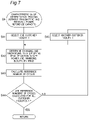
FIG. 7 is a subroutine showing a characteristic value determination process of step S6 in FIG. 3.
FIG. 8 is a subroutine showing a charging and discharging plan determination process of step S7 in FIG. 3.
FIG. 9 is a set of graphs showing exemplary temporal variations in demand power, buying and selling power, generated power, and charging and discharging power of each of the customer facilities 1 of FIG. 1, in a case without transmitting and receiving power among the customer facilities 1.
FIG. 10 is a graph showing exemplary temporal variations in charged electric energy of each of power storage apparatuses 13 of the customer facilities 1 of FIG. 1, in the case without transmitting and receiving power among the customer facilities 1.
FIG. 11 is a graph for explaining determination of a reference capacity of the power storage apparatus 13 in step S2 of FIG. 3.
FIG. 12 is a set of graphs showing exemplary temporal variations in demand power, buying and selling power, generated power, and charging and discharging power of each of the customer facilities 1 of FIG. 1, in a case with transmitting and receiving power among the customer facilities 1 and without constraints on charging and discharging of the power storage apparatuses 13.
FIG. 13 is a graph showing exemplary temporal variations in charged electric energy of each of the power storage apparatuses 13 of the customer facilities 1 of FIG. 1, in the case with transmitting and receiving power among the customer facilities 1 and without constraints on charging and discharging of the power storage apparatuses 13.
FIG. 14 is a set of graphs showing exemplary temporal variations in demand power, buying and selling power, generated power, and charging and discharging power of each of the customer facilities 1 of FIG. 1, in a case with transmitting and receiving power among the customer facilities 1 and with constraints on charging and discharging of the power storage apparatuses 13.
FIG. 15 is a graph showing exemplary temporal variations in charged electric energy of each of the power storage apparatuses 13 of the customer facilities 1 of FIG. 1, in the case with transmitting and receiving power among the customer facilities 1 and with constraints on charging and discharging of the power storage apparatuses 13.
FIG. 16 is a graph showing exemplary degradation rates of the power storage apparatuses 13 in the case without transmitting and receiving power among the customer facilities 1 of FIG. 1, in the case with transmitting and receiving power among the customer facilities 1 of FIG. 1 and without constraints on charging and discharging of the power storage apparatuses 13, and in the case with transmitting and receiving power among the customer facilities 1 of FIG. 1 and with constraints on charging and discharging of the power storage apparatuses 13.
FIG. 17 is a graph showing exemplary temporal variations in total buying and selling power and total charging and discharging power of the customer facilities 1 of FIG. 1, in the case with transmitting and receiving power among the customer facilities 1 and without constraints on charging and discharging of the power storage apparatuses 13.
FIG. 18 is a graph showing exemplary temporal variations in total buying and selling power and total charging and discharging power of the customer facilities 1 of FIG. 1, in the case with transmitting and receiving power among the customer facilities 1 and with constraints on charging and discharging of the power storage apparatuses 13.
FIG. 19 is a flowchart showing a second power control process executed by the power controller apparatus 4 of FIG. 1.
FIG. 20 is a subroutine showing a power prediction process of step S102 in FIG. 19.
FIG. 21 is a subroutine showing a reference capacity determination process of step S103 in FIG. 19.
FIG. 22 is a subroutine showing an actual capacity determination process of step S104 in FIG. 19.
FIG. 23 is a graph for explaining an objective function fa used by a power system according to a first modified embodiment of the first embodiment.
FIG. 24 is a graph for explaining objective functions fb, fc used by a power system according to a second modified embodiment of the first embodiment.
FIG. 25 is a graph for explaining objective functions fd, fe used by a power system according to a third modified embodiment of the first embodiment.
FIG. 26 is a graph for explaining an objective function ff used by a power system according to a fourth modified embodiment of the first embodiment.
FIG. 27 is a block diagram of a configuration of a customer facility 1A included in a power system according to a second embodiment.
FIG. 28 is a block diagram of a configuration of a customer facility 1B included in the power system according to the second embodiment.
FIG. 29 is a block diagram of a configuration of a customer facility 1C included in the power system according to the second embodiment.
FIG. 30 is a block diagram of a configuration of a power system according to a third embodiment.
FIG. 31 is a flowchart showing a power control process executed by a power controller apparatus 4A of FIG. 30.
DESCRIPTION OF EMBODIMENTS
Hereinafter, embodiments of the present disclosure will be described with reference to the drawings.
First Embodiment
[Configuration of Power System]
FIG. 1 is a block diagram of a configuration of a power system according to a first embodiment. The power system of FIG. 1 includes a plurality of customer facilities 1-1 to 1-3, a power network 2, a power company facility 3, and a power controller apparatus 4.
The plurality of customer facilities 1-1 to 1-3 are connected to each other via the power network 2, and further connected to the power company facility 3 via the power network 2.
The power company facility 3 is a power supply facility of a power company (such as power operator, system operator), including power plants, substations, a transmission network, a distribution network, and the like, from which the customer facilities 1-1 to 1-3 are supplied with commercial power (buy power) via the power network 2. A maximum (peak) of power received by each of the customer facilities 1-1 to 1-3 from the power company facility 3 is limited to a predetermined threshold or less by a contract between a customer and the power company. In the present specification, this threshold is also referred to as “peak reduction target power” or a “first threshold”. In addition, in accordance with the contract between the customer and the power company, different electricity prices may be set for the power received by the customer facility 1-1 to 1-3 from the power company facility 3, depending on the time of day (for example, a nighttime electricity price may be lower than a daytime electricity price). In addition, in accordance with the contract between the customer and the power company, the customer facility 1-1 to 1-3 may supply power (sell power) to the power company facility 3.
The customer facility 1-1 is provided with a customer controller apparatus 10, a load apparatus 11, a power generator apparatus 12, and a power storage apparatus 13. The customer facility 1-1 is a home, a store, a factory, or the like, equipped with these components.
The load apparatus 11 includes various electrical appliances, and has demand power to be consumed by the electrical appliances.
The power generator apparatus 12 generates generated power by, for example, a renewable energy generator, such as a solar cell or a wind power generator.
The power storage apparatus 13 is charged with generated power generated by the power generator apparatus 12, commercial power supplied from the power company facility 3, or power transmitted from the other customer facilities 1-2 to 1-3.
The customer controller apparatus 10 monitors the demand power of the load apparatus 11, the generated power of the power generator apparatus 12, and a charged electric energy of the power storage apparatus 13 (that is, electric energy currently stored in the power storage apparatus 13), and notifies the power controller apparatus 4 of the monitored results. For example, the customer controller apparatus 10 may be integrated into a power distribution panel or a switch board, or may be electrically connected to the power distribution panel or the switch board.
The other customer facilities 1-2 to 1-3 are also configured in a manner similar to that of the customer facility 1-1. In the present specification, the customer facilities 1-1 to 1-3 are also collectively referred to as “customer facilities 1”.
The same or different peak reduction target power may be set to the customer facilities 1. The same or different capacity may be set to the power storage apparatuses 13 of the customer facilities 1.
The customer facilities 1 transmit and receive power to and from each other. In order to simultaneously transmit power among a plurality of sets of customer facilities 1 via a common power line, the customer facilities 1 may modulate and transmit power by code modulation using modulation codes orthogonal to each other.
The power controller apparatus 4 controls charging and discharging of the power storage apparatuses 13 of the customer facilities 1, and further controls transmitting and receiving power among the customer facilities 1.
FIG. 2 is a block diagram of a configuration of the power controller apparatus 4 of FIG. 1. The power controller apparatus 4 is provided with a memory device 21, a predictor 22, a reference capacity determiner 23, an actual capacity determiner 24, a characteristic value determiner 25, and a charging and discharging plan determiner 26.
The memory device 21 stores, for each customer facility 1, at least a part of past temporal variations in demand power, past temporal variations in generated power, information on the load apparatus 11, information on the power generator apparatus 12, and user information. The information on the load apparatus 11 includes, for example, rated power consumption of the load apparatus 11. The information on the power generator apparatus 12 includes, for example, rated output power of the power generator apparatus 12. The user information includes, for example, the number, ages, schedules (at home or absent), etc. of members of each customer facility 1. In addition, the memory device 21 may store weather information acquired from an external third-party server apparatus (not shown).
The predictor 22 predicts temporal variations in demand power of the load apparatus 11 and generated power of the power generator apparatus 12 of each customer facility 1 for a time interval of a predetermined length from the current time to a future time (in the present specification, referred to as a “unit time interval”), based on the information stored in the memory device 21. The length of the unit time interval may be, for example, several hours, 24 hours, several days, or the like.
The reference capacity determiner 23 determines a capacity of each power storage apparatus 13 based on the predicted temporal variations in demand power and generated power, the capacity being necessary to maintain the power received by each customer facility 1 from the power company facility 3 at the peak reduction target power or lower, under an assumption that power is not transmitted and received among the customer facilities 1. In the present specification, this capacity is referred to as a “reference capacity”. The reference capacity may be set to a minimum capacity satisfying the above-mentioned conditions.
The actual capacity determiner 24 determines a capacity of each power storage apparatus 13 based on the predicted temporal variations in demand power and generated power, the capacity being necessary to maintain the power received by each customer facility 1 from the power company facility 3 at the peak reduction target power or lower, under an assumption that power is transmitted and received among the customer facilities 1. In the present specification, this capacity is referred to as an “actual capacity”. The actual capacity may be set to a minimum capacity satisfying the above-mentioned conditions.
When power is transmitted and received among the customer facilities 1, the customer facilities 1 share a plurality of the power storage apparatuses 13, and therefore, the actual capacity is smaller than the reference capacity. The customer facilities 1 are provided with the power storage apparatuses 13 having the actual capacities, respectively.
The characteristic value determiner 25 determines a charging and discharging plan for controlling charging and discharging of the power storage apparatuses 13, under an assumption that power is not transmitted and received among the customer facilities 1 and that each power storage apparatus 13 has the reference capacity. Specifically, under this assumption, the characteristic value determiner 25 determines the charging and discharging plan of each power storage apparatus 13 for the unit time interval based on the predicted temporal variations in demand power and generated power, so as to maintain the power received by each customer facility 1 from the power company facility 3 at the peak reduction target power or lower. The characteristic value determiner 25 calculates a characteristic value associated with a degree of degradation of each power storage apparatus 13 for the unit time interval, under an assumption that charging and discharging of the power storage apparatus 13 having the reference capacity are controlled in accordance with this charging and discharging plan. The characteristic value is, for example, the number of charging and discharging cycles of each power storage apparatus 13 for the unit time interval. An increase in the number of charging and discharging cycles represents degradation of the power storage apparatus 13. In the present specification, the number of charging and discharging cycles determined by the characteristic value determiner 25 is also referred to as a “reference number of cycles” or a “first characteristic value”.
The charging and discharging plan determiner 26 determines a charging and discharging plan for controlling charging and discharging of the power storage apparatuses 13, under an assumption that power is transmitted and received among the customer facilities 1 and that each power storage apparatus 13 has the actual capacity. Specifically, under this assumption, the charging and discharging plan determiner 26 determines a charging and discharging plan of the power storage apparatuses 13 for the unit time interval based on the predicted temporal variations in demand power and generated power, so as to maintain the power received by each customer facility 1 from the power company facility 3 at the peak reduction target power or lower. The charging and discharging plan determined by the charging and discharging plan determiner 26 includes temporal variations in charging power and discharging power of each power storage apparatus 13 for the unit time interval, and further includes temporal variations in transmitting power and receiving power among the customer facilities 1. The charging and discharging plan determiner 26 calculates a characteristic value associated with the degree of degradation of each power storage apparatus 13 for the unit time interval, that is, the number of charging and discharging cycles of each power storage apparatus 13 for the unit time interval, under an assumption that charging and discharging of the power storage apparatuses 13 having the actual capacities are controlled in accordance with this charging and discharging plan. In the present specification, the number of charging and discharging cycles determined by the charging and discharging plan determiner 26 is also referred to as an “actual number of cycles” or a “second characteristic value”. The charging and discharging plan determiner 26 calculates an objective function f indicating a degree of degradation from the reference number of cycles to the actual number of cycles, and determines a charging and discharging plan of the power storage apparatuses 13 having the actual capacities for the unit time interval so as to minimize the value of the objective function f. An increase in the number of charging and discharging cycles represents degradation from the reference number of cycles to the actual number of cycles.
The customer controller apparatus 10 is provided with a control circuit 10 a and a power distribution panel 10 b. The control circuit 10 a controls the power distribution panel 10 b under control of the power controller apparatus 4. The power distribution panel 10 b is connected to the power company facility 3 via the power network 2, and transmits and receives power to and from the power company facility 3, the load apparatus 11, the power generator apparatus 12, and the power storage apparatus 13.
In the present specification, the number of charging and discharging cycles of a certain power storage apparatus 13 is calculated by dividing the sum of an absolute value of charging electric energy and an absolute value of discharging electric energy for the unit time interval, by the capacity of the power storage apparatus 13 (that is, the reference capacity or the actual capacity).
For example, the objective function f is given as follows.
f = i = 1 N A i × max ( Cb i - Ca i , 0 ) + B i [ Mathematical Expression 1 ]
Where Ai indicates a predetermined weight coefficient of the customer facility 1-i (i=1 to 3), which is set depending on, for example, a unit price of electricity. For example, when the customer facility 1-i is a typical home in Japan, and the electricity price is expressed in Japanese yen, the weight coefficient Ai may be set to, e.g., 0.01. Cai indicates the reference number of cycles of the customer facility 1-i, and Cbi indicates the actual number of cycles of the customer facility 1-i. “Cbi−Cai” indicates a penalty imposed when the actual number of cycles Cbi degrades (that is, increases) from the reference number of cycles Cai. Bi indicates an electricity price determined according to the power received by the customer facility 1-i from the power company facility 3. When the customer facility 1-i sells power to the power company facility 3, the electricity price may be reduced according to the selling power.
The value of the objective function f increases with an increase from the reference number of cycles to the actual number of cycles. In other words, when power is transmitted and received among the customer facilities 1, and the capacity of each power storage apparatus 13 is reduced below the reference capacity, the number of charging and discharging cycles increases as compared to the case where power is not transmitted and received among the customer facilities 1, and each power storage apparatus 13 has the reference capacity. In this case, the value of the objective function f increases with the increase in the number of charging and discharging cycles. In addition, the higher the electricity price is, the larger the value of the objective function f is.
The power control apparatus 4 controls charging and discharging of the power storage apparatuses 13 of the customer facilities 1, and further controls transmitting and receiving power among the customer facilities 1, in accordance with the charging and discharging plan determined by the charging and discharging plan determiner 26.
The power controller apparatus 4 may be implemented as hardware components 21 to 26, or may be implemented as a program that provides the same functions as the components 21 to 26 when executed by a processor.
[Power Control Process]
Hereinafter, operation of the power controller apparatus 4 will be described in more detail with reference to FIGS. 3 to 16.
FIG. 3 is a flowchart showing a first power control process executed by the power controller apparatus 4 of FIG. 1.
In step S1, the predictor 22 executes power prediction process. In this step, the predictor 22 predicts temporal variations in demand power and generated power of each customer facility 1 for the unit time interval. In step S2, the reference capacity determiner 23 executes reference capacity determination process. In this step, the reference capacity determiner 23 determines the reference capacity of each power storage apparatus 13 under an assumption that power is not transmitted and received among the customer facilities 1. In step S3, the actual capacity determiner 24 executes actual capacity determination process. In this step, the actual capacity determiner 24 determines the actual capacity of each power storage apparatus 13 under an assumption that power is transmitted and received among the customer facilities 1.
Steps S1 to S3 are preparatory processes for determining the capacity of each power storage apparatus 13 of the customer facilities 1, to be executed before installing the power storage apparatuses 13 in the customer facilities 1 (that is, before actual operation of the customer facilities 1). In step S4, the power storage apparatuses 13 having the actual capacities determined in step S3 are installed in the customer facilities 1.
In step S5, the predictor 22 executes the power prediction process. In this step, the predictor 22 predicts temporal variations in demand power and generated power of each customer facility 1 for the unit time interval. In step S6, the characteristic value determiner 25 executes characteristic value determination process. In this step, the characteristic value determiner 25 determines a charging and discharging plan of each power storage apparatus 13 for the unit time interval, under an assumption that power is not transmitted and received among the customer facilities 1 and that each power storage apparatus 13 has the reference capacity, and calculates the reference number of cycles when charging and discharging of each power storage apparatus 13 are controlled in accordance with this charging and discharging plan. In step S7, the charging and discharging plan determiner 26 executes charging and discharging plan determination process. In this step, the charging and discharging plan determiner 26 calculates the actual number of cycles when charging and discharging of the power storage apparatuses 13 are controlled under an assumption that power is transmitted and received among the customer facilities 1 and that each power storage apparatus 13 has the actual capacity, and determines a charging and discharging plan of the power storage apparatuses 13 for the unit time interval so as to minimize the value of the objective function f. In step S8, the power controller apparatus 4 controls charging and discharging of the power storage apparatuses 13 of the customer facilities 1 in accordance with the charging and discharging plan determined in step S7. In step S9, when the unit time interval has elapsed, the process returns to step S5, and repeats from steps S5 to S9.
Steps S5 to S9 are operational processes in which the customer facilities 1 are actually operated to control consuming, transmitting, receiving, charging, and discharging power in the customer facilities 1.
[Power Prediction Process]
FIG. 4 is a subroutine showing the power prediction process of steps S1 and S5 in FIG. 3.
In step S11 of FIG. 4, the predictor 22 selects one customer facility 1. In step S12, the predictor 22 determines whether or not there is data on past demand power and past generated power of the selected customer facility 1 in the memory device 21; if YES, the process proceeds to step S13, and if NO, the process proceeds to step S14. In step S13, the predictor 22 predicts temporal variations in demand power and generated power of the customer facility 1 for the unit time interval, based on the past temporal variations in demand power and generated power of the customer facility 1. In step S14, the predictor 22 predicts temporal variations in demand power and generated power of the customer facility 1 for the unit time interval, based on the information on the load apparatus 11, the power generator apparatus 12, and the users stored in the memory device 21. In step S15, the predictor 22 determines whether or not the prediction of demand power and generated power has been done for all the customer facilities 1; if YES, the process proceeds to step S2 of FIG. 3, and if NO, the process proceeds to step S16 of FIG. 4. In step S16, the predictor 22 selects another customer facility 1, and then repeats steps S12 to S15.
In step S13, the predictor 22 may predict temporal variations in demand power and generated power of the customer facility 1 for the unit time interval, by referring to the information on the load apparatus 11, the power generator apparatus 12, and the users, in addition to the past temporal variations in demand power and generated power of the customer facility 1.
In step S1, the predictor 22 may use the data on demand power and generated power of each customer facility 1 over a past long period (for example, one year to several years), in order to appropriately determine the capacity (actual capacity) of each power storage apparatus 13. For example, the predictor 22 may extract and average demand power at the same time on every day from the demand power over the past long period, thus generating a set of averages of the demand power per time of day. In addition, the predictor 22 may extract a maximum of demand power at the same time on every day from the demand power over the past long period, thus generating a set of maximums of the demand power per time of day. The set of the demand power generated in such manners represents predicted temporal variations in demand power. In addition, the predictor 22 may extract and average generated power at the same time on every day from the generated power over the past long period, thus generating a set of averages of the generated power per time of day. In addition, the predictor 22 may extract a minimum of generated power at the same time on every day from the generated power over the past long period, thus generating a set of minimums of the generated power per time of day. The set of the generated power generated in such manners represents predicted temporal variations in generated power.
In addition, in step S1, the predictor 22 may use weather information over a past long period, such as, for example, an average, maximum, or minimum of weather (for example, duration of sunshine) and/or temperature, per time of day, in order to predict the temporal variations in demand power and generated power.
On the other hand, in step S5, the predictor 22 may use data on demand power and generated power of the same day of week or the same date as when step S5 is being executed, from the data on past demand power and past generated power of each customer facility 1, in order to appropriately determine the charging and discharging plan.
In addition, in step S5, the predictor 22 may use current weather information, and/or weather forecasts over a short-term future (for example, several hours to 24 hours), in order to predict the temporal variations in demand power and generated power.
[Reference Capacity Determination Process (Step S2)]
FIG. 5 is a subroutine showing the reference capacity determination process of step S2 in FIG. 3.
In step S21 of FIG. 5, the reference capacity determiner 23 selects one customer facility 1. In step S22, the reference capacity determiner 23 sets an initial reference capacity for the power storage apparatus 13 of the selected customer facility 1. In step S23, the reference capacity determiner 23 determines a charging and discharging plan of the power storage apparatus 13, under an assumption that power is not transmitted and received among the customer facilities 1 and that the power storage apparatus 13 has the reference capacity currently set. Specifically, under this assumption, the reference capacity determiner 23 determines a charging and discharging plan of the power storage apparatus 13 for the unit time interval based on the temporal variations in demand power and generated power predicted in step S1, so as to maintain the power received by the selected customer facility 1 from the power company facility 3 at the peak reduction target power or lower.
FIG. 9 is a set of graphs showing exemplary temporal variations in demand power, buying and selling power, generated power, and charging and discharging power of each of the customer facilities 1 of FIG. 1, in a case without transmitting and receiving power among the customer facilities 1.
The customer facilities 1-1 to 1-3 have the demand power different from each other. Referring to each graph of FIG. 9 (and FIGS. 12, 14, 17, and 18), in plots of the buying and selling power, positive power indicates buying power, and negative power indicates selling power. In addition, referring to each graph of FIG. 9 (and FIGS. 12, 14, 17, and 18), in plots of the charging and discharging power, positive power indicates discharging power, and negative power indicates charging power. The power generator apparatuses 12 of the customer facilities 1-1 to 1-3 are solar cells operating under the same weather conditions (that is, installed at locations close to each other), and their temporal variations in generated power are assumed to be the same with each other. The customers have their respective contracts with the power company for the same unit prices of electricity (for example, 25 yen/kWh from 6:00 to 25:00 (1:00); 17 yen/kWh from 1:00 to 6:00). The peak reduction target power of 1 kW is set for each of the customer facilities 1-1 to 1-3 by the contracts between the customers and the power company. In addition, in each graph of FIG. 9 (and FIGS. 12, 14, 17, and 18), the unit time interval is 24 hours.
Referring to the top of FIG. 9, from 1:00 to 5:00, the customer facility 1-1 buys power from the power company facility 3 and charges the power storage apparatus 13 in advance, in order to cope with the increase in the demand power and the like predicted to occur at a later time. From 7:00 to 9:00, the customer facility 1-1 discharges the power storage apparatus 13 according to the increase in the demand power, and consumes the discharged power by the load apparatus 11. From 9:00 to 12:00, the generated power exceeds the demand power, and the customer facility 1-1 charges the power storage apparatus 13 with the excess of the generated power. From 16:00 to 18:00, the customer facility 1-1 discharges the power storage apparatus 13 in order to compensate for the decrease in the generated power, and consumes the discharged power by the load apparatus 11. Around 20:00, the demand power increases beyond the peak reduction target power. From 19:00 to 21:00, the customer facility 1-1 discharges the power storage apparatus 13 according to the increase in the demand power, and consumes the discharged power by the load apparatus 11.
Referring to the middle of FIG. 9, from 0:00 to 2:00, the customer facility 1-2 buys power from the power company facility 3 and charges the power storage apparatus 13. From 5:00 to 8:00, the customer facility 1-2 reduces the buying power, discharges the power storage apparatus 13, and consumes the discharged power by the load apparatus 11, in advance, in order to cope with the increase in the generated power predicted to occur at a later time. From 8:00 to 17:00, the generated power exceeds the demand power, and the customer facility 1-2 charges the power storage apparatus 13 with the excess of the generated power, and further sells the excess of the generated power to the power company facility 3. From 21:00 to 23:00, the demand power increases beyond the peak reduction target power, and the customer facility 1-2 discharges the power storage apparatus 13 according to the increase in the demand power, and consumes the discharged power by the load apparatus 11.
Referring to the bottom of FIG. 9, from 0:00 to 5:00, the customer facility 1-3 buys power from the power company facility 3 and charges the power storage apparatus 13, in order to cope with the increase in the demand power and the like predicted to occur at a later time. From 8:00 to 10:00, the demand power increases beyond the peak reduction target power, and the customer facility 1-3 discharges the power storage apparatus 13 according to the increase in the demand power, and consumes the discharged power by the load apparatus 11. From 10:00 to 17:00, the generated power exceeds the demand power, and the customer facility 1-3 charges the power storage apparatus 13 with the excess of the generated power, and further sells the excess of the generated power to the power company facility 3. From 21:00 to 24:00, the customer facility 1-3 reduces the buying power, discharges the power storage apparatus 13, and consumes the discharged power by the load apparatus 11.
When the temporal variations in demand power and generated power of each customer facility 1 are predicted, for example, as shown in FIG. 9, the charging and discharging plans of the power storage apparatuses 13 of the customer facilities 1 in the case without transmitting and receiving power among the customer facilities 1 are determined, for example, as shown by the plots of the charging and discharging power of FIG. 9.
FIG. 10 is a graph showing exemplary temporal variations in charged electric energy of each of the power storage apparatuses 13 of the customer facilities 1 of FIG. 1, in the case without transmitting and receiving power among the customer facilities 1. FIG. 10 shows the temporal variations in charged electric energy when the charging and discharging power of each customer facility 1 varies as shown in FIG. 9. Assume that the reference capacities of 2.1 kWh, 1.4 kWh, and 1.8 kWh are set for the power storage apparatuses 13 of the customer facilities 1-1, 1-2, and 1-3, respectively. The number of charging and discharging cycles of each of the power storage apparatuses 13 of the customer facilities 1 is calculated based on the reference capacity of the power storage apparatus 13, and based on the increase and decrease in the charged electric energy of the power storage apparatus 13 (that is, charging electric energy and discharging electric energy) as shown in FIG. 10. In the example of FIG. 10, the power storage apparatuses 13 of the customer facilities 1-1, 1-2, and 1-3 have the numbers of charging and discharging cycles of 2.1, 2.4, and 3.1, respectively.
In step S24 of FIG. 5, the reference capacity determiner 23 predicts a payback period of the power storage apparatus 13. For this purpose, the reference capacity determiner 23 calculates a first electricity price in a case where the contract between the customer and the power company allows the customer facility 1 to receive peak demand power from the power company facility 3. In addition, the reference capacity determiner 23 calculates a second electricity price in a case where the contract between the customer and the power company allows the customer facility 1 to receive power up to the peak reduction target power from the power company facility 3. In this cases, the first and second electricity prices are expressed, for example, in units of [yen/month] or [yen/year]. The difference between the first and second electricity prices is a reduction in electricity price achieved by using the power storage apparatus 13. The payback period is calculated by dividing a price of the power storage apparatus 13 by the reduction in electricity price achieved by using the power storage apparatus 13.
FIG. 11 is a graph for explaining the determination of the reference capacity of the power storage apparatus 13 in step S2 of FIG. 3. The larger the capacity of the power storage apparatus 13 is, the lower the peak reduction target power can be. However, the larger the capacity of the power storage apparatus 13 is, the higher the price of the power storage apparatus 13 is, and therefore, the longer the payback period is. On the other hand, the smaller the capacity of the power storage apparatus 13 is, the lower the price of the power storage apparatus 13 is. However, the smaller the capacity of the power storage apparatus 13 is, the more difficult it is to reduce the peak reduction target power, and therefore, the longer the payback period is. Therefore, the reference capacity of the power storage apparatus 13 is determined so as to minimize the payback period.
In step S25 of FIG. 5, the reference capacity determiner 23 determines whether or not the payback period is minimized; if YES, the process proceeds to step S26, and if NO, the process proceeds to step S27. In step S26, the reference capacity determiner 23 determines the reference capacity currently set, as the reference capacity of the power storage apparatus 13. In step S27, the reference capacity determiner 23 changes the reference capacity of the power storage apparatus 13. The reference capacity determiner 23 may change the reference capacity of the power storage apparatus 13, for example, by a predetermined step size, or by a variable step size using a steepest gradient method or the like. The step size may be expressed as capacity, or as a ratio to the reference capacity currently set.
In step S28, the reference capacity determiner 23 determines whether or not the reference capacities are determined for all the customer facilities 1; if YES, the process proceeds to step S3 of FIG. 3, and if NO, the process proceeds to step S29 of FIG. 5. In step S29, the reference capacity determiner 23 selects another customer facility 1, and repeats steps S22 to S28.
By executing the reference capacity determination process of step S2 in such a manner, it is possible to determine the reference capacity sufficient to maintain the power received by each customer facility 1 from the power company facility 3 at the peak reduction target power or lower, under the assumption that power is not transmitted and received among the customer facilities 1.
The reference capacity determiner 23 may determine the reference capacities for the customer facilities 1, respectively, as shown in FIG. 5. Alternatively, the reference capacity determiner 23 may determine one reference capacity common to the customer facilities 1.
[Actual Capacity Determination Process (Step S3)]
FIG. 6 is a subroutine showing the actual capacity determination process of step S3 in FIG. 3.
In step S31 of FIG. 6, the actual capacity determiner 24 sets the reference capacities of the power storage apparatuses 13 of the customer facilities 1 determined in step S2 of FIG. 3, as initial actual capacities of the power storage apparatuses 13 of the customer facilities 1.
In step S32, the actual capacity determiner 24 changes the actual capacities of the power storage apparatuses 13 of the customer facilities 1. The actual capacity determiner 24 may change the actual capacities of the power storage apparatuses 13, for example, by a predetermined step size, or by a variable step size using a steepest gradient method or the like. The step size may be expressed as capacity, or as a ratio to the actual capacity currently set. The same or different step size may be set to the customer facilities 1.
In step S33, the actual capacity determiner 24 tries to determine a charging and discharging plan of the power storage apparatuses 13, under an assumption that power is transmitted and received among the customer facilities 1 and that each power storage apparatus 13 has the actual capacity currently set. Specifically, under this assumption, the actual capacity determiner 24 tries to determine the charging and discharging plan of the power storage apparatuses 13 for the unit time interval based on the temporal variations in demand power and generated power predicted in step S1, so as to maintain the power received by each customer facility 1 from the power company facility 3 at the peak reduction target power or lower.
FIG. 12 is a set of graphs showing exemplary temporal variations in demand power, buying and selling power, generated power, and charging and discharging power of each of the customer facilities 1 of FIG. 1, in a case with transmitting and receiving power among the customer facilities 1 and without constraints on charging and discharging of the power storage apparatuses 13.
In this case, the term “constraints on charging and discharging power” means that charging and discharging of the power storage apparatuses 13 are controlled so as to reduce the characteristic value associated with the degree of degradation of each power storage apparatus 13, that is, an increase in the number of charging and discharging cycles, as small as possible, with respect to the case without transmitting and receiving power among the customer facilities 1.
The demand power and the generated power of each of the customer facilities 1-1 to 1-3 in FIG. 12 are the same as those shown in FIG. 9.
Referring to the top, middle, and bottom of FIG. 12, from 0:00 to 5:00, each of the customer facilities 1-1 to 1-3 buys power from the power company facility 3 and charges the power storage apparatus 13, in a manner similar to that of FIG. 9. However, in the case of FIG. 12, since power may be transmitted and received among the customer facilities 1-1 to 1-3, the buying power and the charging power from 0:00 to 5:00 are higher or lower than those of FIG. 9.
In addition, as explained with reference to FIG. 9, from 8:00 to 10:00, the demand power of the customer facility 1-3 increases beyond the peak reduction target power, the customer facility 1-3 discharges the power storage apparatus 13, and consumes the discharged power by the load apparatus 11. Therefore, as shown in FIG. 10, the charged electric energy of the power storage apparatus 13 of the customer facility 1-3 becomes close to zero around 10:00. On the other hand, in the case of FIG. 12, from 6:00 to 9:00, the customer facility 1-1 transmits a part of the discharging power of the power storage apparatus 13 to the customer facility 1-3, and the load apparatus 11 of the customer facility 1-3 consumes the power received from the customer facility 1-1. As a result, in the case of FIG. 12, the discharging power of the power storage apparatus 13 of the customer facility 1-1 from 6:00 to 9:00 is higher than that of FIG. 9, and thus, the increase in the number of charging and discharging cycles of the power storage apparatus 13 of the customer facility 1-1 becomes larger than that of FIG. 9.
In addition, as explained with reference to FIG. 9, in the customer facility 1-2, the generated power exceeds the demand power from 8:00 to 17:00, and in the customer facility 1-3, the generated power exceeds the demand power from 10:00 to 17:00. Then in the case of FIG. 9, each of the customer facilities 1-2, 1-3 charges the power storage apparatus 13 with the excess of the generated power, and further sells the excess of the generated power to the power company facility 3. On the other hand, in the case of FIG. 12, from 9:00 to 15:00, each of the customer facilities 1-2, 1-3 transmits the excess of the generated power to the customer facility 1-1, instead of selling the power to the power company facility 3, and the customer facility 1-1 charges the power storage apparatus 13 with the power received from each of the customer facilities 1-2, 1-3. As a result, in the case of FIG. 12, the charging power of the power storage apparatus 13 of the customer facility 1-1 from 9:00 to 15:00 is higher than that of FIG. 9, and thus, the increase in the number of charging and discharging cycles of the power storage apparatus 13 of the customer facility 1-1 becomes larger than that of FIG. 9. In addition, in the case of FIG. 12, since the selling power is reduced, it is possible to reduce influence on the power company facility 3 as compared to the case of FIG. 9.
In addition, as explained with reference to FIG. 9, from 21:00 to 23:00, the demand power of the customer facility 1-2 increases beyond the peak reduction target power, and the customer facility 1-2 discharges the power storage apparatus 13, and consumes the discharged power by the load apparatus 11. Therefore, as shown in FIG. 10, the charged electric energy of the power storage apparatus 13 of the customer facility 1-2 becomes close to zero around 24:00. On the other hand, in the case of FIG. 12, the power storage apparatus 13 of the customer facility 1-1 is charged with the power received from each of the customer facilities 1-2, 1-3 from 9:00 to 15:00 as described above, and thus, has higher charged electric energy from 21:00 to 23:00 than that of FIG. 9. Accordingly, in the case of FIG. 12, from 21:00 to 23:00, the customer facility 1-1 transmits a part of the discharging power of the power storage apparatus 13 to the customer facility 1-2, and the load apparatus 11 of the customer facility 1-2 consumes the power received from the customer facility 1-1. As a result, in the case of FIG. 12, the discharging power of the power storage apparatus 13 of the customer facility 1-1 from 21:00 to 23:00 is higher than that of FIG. 9, and thus, the increase in the number of charging and discharging cycles of the power storage apparatus 13 of the customer facility 1-1 becomes larger than that of FIG. 9.
When the temporal variations in demand power and generated power of each customer facility 1 are predicted, for example, as shown in FIG. 12, the charging and discharging plan of the power storage apparatuses 13 of the customer facilities 1 in the case with transmitting and receiving power among the customer facilities 1 are determined, for example, as shown by the plots of the charging and discharging power of FIG. 12.
FIG. 13 is a graph showing exemplary temporal variations in charged electric energy of each of the power storage apparatuses 13 of the customer facilities 1 of FIG. 1, in the case with transmitting and receiving power among the customer facilities 1 and without constraints on charging and discharging of the power storage apparatuses 13. FIG. 13 shows the temporal variations in charged electric energy when the charging and discharging power of each customer facility 1 varies as shown in FIG. 12. Assume that the actual capacities of 1.5 kWh, 1.0 kWh, and 1.3 kWh are set for the power storage apparatuses 13 of the customer facilities 1-1, 1-2, and 1-3, respectively. The number of charging and discharging cycles of each of the power storage apparatuses 13 of the customer facilities 1 is calculated based on the actual capacity of the power storage apparatus 13, and based on the increase and decrease in the charged electric energy of the power storage apparatus 13 (that is, a charging electric energy and a discharging electric energy) as shown in FIG. 13. In the example of FIG. 13, each of the power storage apparatuses 13 of the customer facilities 1-1, 1-2, and 1-3 has the number of charging and discharging cycles of 3.1.
FIG. 13 shows that by transmitting and receiving power among the customer facilities 1-1 to 1-3, the capacity necessary for each of the power storage apparatuses 13 of the customer facilities 1-1 to 1-3 decreases as compared to the case of FIG. 10. However, since no constraint is imposed on charging and discharging of the power storage apparatuses 13 in the case of FIG. 13, the number of charging and discharging cycles of each of the power storage apparatuses 13 of the customer facilities 1-1 to 1-3 may increase as compared to the case of FIG. 10.
In step S33 of FIG. 6, the actual capacity determiner 24 determines whether or not the charging and discharging plan can be determined so as to satisfy the peak reduction target powers of the customer facilities 1; if YES, the process proceeds to step S34, and if NO, the process returns to step S32. In step S34, the actual capacity determiner 24 determines whether or not the actual capacities of the power storage apparatuses 13 of the customer facilities 1 are minimized; if YES, the process proceeds to step S35, and if NO, the process returns to step S32 and repeats steps S32 to S34. In step S35, the actual capacity determiner 24 determines the actual capacities currently set, as the actual capacities of the power storage apparatuses 13 for the customer facilities 1.
In this way, by executing the actual capacity determination process of step S3, it is possible to determine the actual capacities sufficient to maintain the power received by each customer facility 1 from the power company facility 3 at the peak reduction target power or lower, under the assumption that power is transmitted and received among the customer facilities 1.
The actual capacity determiner 24 may determine the actual capacities for the customer facilities 1, respectively, or may determine one actual capacity common to the customer facilities 1.
[Characteristic Value Determination Process (Step S6)]
FIG. 7 is a subroutine showing the characteristic value determination process of step S6 in FIG. 3.
In step S41 of FIG. 7, the characteristic value determiner 25 selects one customer facility 1.
In step S42, the characteristic value determiner 25 determines a charging and discharging plan of the power storage apparatus 13 of the customer facility 1 selected in step S41, under an assumption that power is not transmitted and received among the customer facilities 1 and that each power storage apparatus 13 has the reference capacity. Specifically, under this assumption, the characteristic value determiner 25 determines a charging and discharging plan of the power storage apparatus 13 for the unit time interval based on the temporal variations in demand power and generated power predicted in step S5, so as to maintain the power received by the customer facility 1 from the power company facility 3 at the peak reduction target power or lower, and to minimize the electricity price for the power received by the customer facility 1 from the power company facility 3. In step S43, the characteristic value determiner 25 calculates the reference number of cycles of the power storage apparatus 13 of the customer facility 1, under an assumption that charging and discharging of the power storage apparatus 13 having the reference capacity are controlled in accordance with this charging and discharging plan determined in step S42.
In step S44, the characteristic value determiner 25 determines whether or not the reference numbers of cycles are determined for all the customer facilities 1; if YES, the process proceeds to step S7 of FIG. 3, and if NO, the process proceeds to step S45 of FIG. 7. In step S45, the characteristic value determiner 25 selects another customer facility 1, and repeats steps S42 to S44.
[Charging and Discharging Plan Determination Process (Step S7)]
FIG. 8 is a subroutine showing the charging and discharging plan determination process of step S7 in FIG. 3.
In step S51 of FIG. 8, the charging and discharging plan determiner 26 determines a charging and discharging plan of the power storage apparatuses 13, under an assumption that power is transmitted and received among the customer facilities 1 and that each power storage apparatus 13 has the actual capacity. Specifically, under this assumption, the charging and discharging plan determiner 26 determines a charging and discharging plan of the power storage apparatuses 13 for the unit time interval based on the temporal variations in demand power and generated power predicted in step S5, so as to maintain the power received by each customer facility 1 from the power company facility 3 at the peak reduction target power or lower.
In step S52, the charging and discharging plan determiner 26 calculates the actual number of cycles of each of the power storage apparatuses 13 of the customer facilities 1, under an assumption that charging and discharging of the power storage apparatuses 13 having the actual capacities are controlled in accordance with the charging and discharging plan determined in step S51. In step S53, the charging and discharging plan determiner 26 calculates the total electricity price of the customer facilities 1, under an assumption that charging and discharging of the power storage apparatuses 13 having the actual capacities are controlled in accordance with the charging and discharging plan determined in step S51. In step S54, the charging and discharging plan determiner 26 calculates the value of the objective function f of the customer facilities 1, based on the reference numbers of cycles, the actual numbers of cycles, and the electricity price.
In step S55 of FIG. 8, the charging and discharging plan determiner 26 determines whether or not the value of the objective function f is minimized; if YES, the process proceeds to step S8 of FIG. 3, and if NO, the process proceeds to step S51 of FIG. 8 and repeats steps S51 to S55.
When satisfying demand power of a certain customer facility 1, the value of the objective function f is reduced by consuming power generated by that customer facility 1 or other customer facilities 1, instead of buying and consuming power from the power company facility 3. In addition, when satisfying demand power of a certain customer facility 1, the value of the objective function f is reduced by buying power from the power company facility 3 and charging the power storage apparatus 13 in advance before the demand power occurs, when the electricity price is lower, instead of buying and consuming power from the power company facility 3 in real time. In addition, when satisfying demand power of a certain customer facility 1, depending on conditions, the value of the objective function f may be reduced by consuming power discharged from the power storage apparatus 13 of that customer facility 1 or other customer facilities 1, instead of buying and consuming power from the power company facility 3. Alternatively, when satisfying demand power of a certain customer facility 1, depending on conditions, the value of the objective function f may be reduced by buying and consuming power from the power company facility 3, instead of consuming power discharged from the power storage apparatus 13 of that customer facility 1 or other customer facilities 1. The value of the objective function f can be reduced by arbitrarily combining these and other operations to determine a charging and discharging plan of the power storage apparatuses 13.
FIG. 14 is a set of graphs showing exemplary temporal variations in demand power, buying and selling power, generated power, and charging and discharging power of each of the customer facilities 1 of FIG. 1, in a case with transmitting and receiving power among the customer facilities 1 and with constraints on charging and discharging of the power storage apparatuses 13.
By minimizing the value of the objective function f, it is possible to satisfy the constraints on the charging and discharging so as to reduce the increase in the number of charging and discharging cycles as small as possible, as described above.
The demand power and the generated power of each of the customer facilities 1-1 to 1-3 in FIG. 14 are the same as those shown in FIG. 9.
Referring to the top and the middle of FIG. 14, from 0:00 to 5:00, each of the customer facilities 1-1, 1-2 reduces power bought from the power company facility 3 and charging the power storage apparatus 13, than that of FIG. 12. Accordingly, from 0:00 to 5:00, the increase in the number of charging and discharging cycles of the power storage apparatus 13 of each of the customer facilities 1-1, 1-2 is smaller than that of FIG. 12.
Referring to the top of FIG. 14, from 7:00 to 9:00, the customer facility 1-1 reduces power discharged from the power storage apparatus 13 and transmitted to the customer facility 1-3, than that of FIG. 12. Accordingly, from 7:00 to 9:00, the increase in the number of charging and discharging cycles of the power storage apparatus 13 of the customer facility 1-1 is smaller than that of FIG. 12. Referring to the bottom of FIG. 14, from 7:00 to 9:00, the customer facility 1-3 reduces power received from the customer facility 1-1 than that of FIG. 12, and increases power received from the power company facility 3 than that of FIG. 12.
Referring to the middle of FIG. 14, from 9:00 to 13:00, the customer facility 1-2 reduces power charging the power storage apparatus 13 than that of FIG. 12, and instead, increases power transmitted to the customer facility 1-1 than that of FIG. 12. Referring to the bottom of FIG. 14, from 10:00 to 14:00, the customer facility 1-3 increases power sold to the power company facility 3 than that of FIG. 12, and instead, reduces power transmitted to the customer facility 1-1 than that of FIG. 12. Referring to the top of FIG. 14, from 9:00 to 15:00, the customer facility 1-1 reduces power received from the customer facilities 1-2, 1-3 and charging the power storage apparatus 13, than that of FIG. 12. Accordingly, from 9:00 to 15:00, the increase in the number of charging and discharging cycles of the power storage apparatus 13 of the customer facility 1-1 is smaller than that of FIG. 12.
Each customer facility 1 may use the generated power of the power generator apparatus 12, the buying power from the power company facility 3, and/or the receiving power from other customer facilities 1 to be consumed by the load apparatus 11, without charging the power storage apparatus 13, or mat temporarily charge the power storage apparatus 13 for consuming later. It is possible to prevent or reduce the increase in the value of the objective function f by consuming power by the load apparatus 11 without charging the power storage apparatus 13.
When the temporal variations in demand power and generated power of each customer facility 1 are predicted, for example, as shown in FIG. 14, the charging and discharging plan of the power storage apparatuses 13 of the customer facilities 1 in the case with transmitting and receiving power among the customer facilities 1 are determined, for example, as shown by the plots of the charging and discharging power of FIG. 14.
FIG. 15 is a graph showing exemplary temporal variations in charged electric energy of each of the power storage apparatuses 13 of the customer facilities 1 of FIG. 1, in the case with transmitting and receiving power among the customer facilities 1 and with constraints on charging and discharging of the power storage apparatuses 13. FIG. 15 shows the temporal variations in charged electric energy when the charging and discharging power of each customer facility 1 varies as shown in FIG. 14. Assume that the power storage apparatuses 13 of the customer facilities 1-1, 1-2, and 1-3 have the actual capacities of 1.5 kWh, 1.0 kWh, and 1.3 kWh, respectively. The actual number of cycles of each of the power storage apparatuses 13 of the customer facilities 1 is calculated based on the actual capacity of the power storage apparatus 13, and based on the increase and decrease in the charged electric energy of the power storage apparatus 13 (that is, a charging electric energy and a discharging electric energy) as shown in FIG. 15. In the example of FIG. 15, the power storage apparatuses 13 of the customer facilities 1-1, 1-2, and 1-3 have the actual numbers of cycles of 2.1, 2.4, and 3.1, respectively.
FIG. 15 shows that by imposing the constraints on charging and discharging of the power storage apparatuses 13, the numbers of charging and discharging cycles of the power storage apparatuses 13 of the customer facilities 1-1 to 1-3 can be reduced as compared to the case of FIG. 13. In addition, by imposing the constraints on charging and discharging of the power storage apparatuses 13, it is possible to reduce, as compared to the case of FIG. 13, the increase in the numbers of charging and discharging cycles of the power storage apparatuses 13 as compared to the case of FIG. 10, and depending on conditions, it is possible to reduce the numbers of charging and discharging cycles of the power storage apparatuses 13 as compared to the case of FIG. 10.
By repeating steps S51 to S55 of FIG. 8, it is possible to determine a charging and discharging plan of the power storage apparatuses 13 so as to minimize the value of the objective function f.
The objective function f including the term Ai×max(Cbi−Cat, 0) regarding the number of charging and discharging cycles means that the constraint is imposed so as to reduce the increase from reference number of cycles Cai to the actual number of cycles Cbi, and preferably, to make the actual number of cycles Cbi smaller than the reference number of cycles Cai. When this constraint is satisfied, even if power is transmitted and received among the customer facilities 1, the power storage apparatuses 13 are shared among the customer facilities 1, the power storage apparatuses 13 are less likely to significantly degrade, and preferably, the power storage apparatuses 13 are less likely to degrade, as compared to the case without transmitting and receiving power among the customer facilities 1.
In addition, in the power control process of FIG. 3, the relationship between the reference number of cycles and the actual number of cycles (penalty) is set not as hard constraints, but as soft constraints. For example, when the demand power predicted in step S5 of FIG. 3 is higher than the demand power predicted in step S1, and/or the when generated power predicted in step S5 is lower than the generated power predicted in step S1, the actual number of cycles may degrade (that is, increase) from the reference number of cycles. Even in such a case, since the relationship between the reference number of cycles and the actual number of cycles is set as soft constraints, it is possible to determine a charging and discharging plan of the power storage apparatuses 13 so as to reduce the increase from the reference number of cycles to the actual number of cycles as small as possible to minimize the value of the objective function f.
In addition, when a small coefficient Ai is set in the objective function f, the actual number of cycles tends to exceed the reference number of cycles, and increase from the reference number of cycles to the actual number of cycles tends to become larger. Consequently, variations in degradation are likely to occur among the power storage apparatuses 13 of the customer facilities 1. On the other hand, when a large coefficient Ai is set, an increase from the reference number of cycles to the actual number of cycles is reduced, or the actual number of cycles is less likely to exceed the reference number of cycles. Thus, variations in degradation are less likely to occur among the power storage apparatuses 13 of the customer facilities 1.
On the other hand, in the power control process of FIG. 3, the peak reduction target power is set as hard constraints. This is because the electricity price substantially changes depending on whether or not the maximum power received by each customer facility 1 from the power company facility 3 exceeds the peak reduction target power.
Advantageous Effects of First Embodiment
FIG. 16 is a graph showing exemplary degradation rates of the power storage apparatuses 13 in the case without transmitting and receiving power among the customer facilities 1 of FIG. 1, in the case with transmitting and receiving power among the customer facilities 1 of FIG. 1 and without constraints on charging and discharging of the power storage apparatuses 13, and in the case with transmitting and receiving power among the customer facilities 1 of FIG. 1 and with constraints on charging and discharging of the power storage apparatuses 13. Simulations were performed under the conditions of FIGS. 9, 12, and 14. In this case, the degradation rate of the power storage apparatus 13 represents a ratio in percentage of a square root of the actual number of cycles to a square root of the reference number of cycles. In other words, the degradation rate of the power storage apparatus 13 represents the degree of degradation expressed by the actual number of cycles, normalized by the degree of degradation expressed by the reference number of cycles.
FIG. 16 shows that when transmitting and receiving power among the customer facilities 1 without the constraints on charging and discharging of the power storage apparatuses 13 the power storage apparatus 13 of at least a part of the customer facilities 1 degrade from the case without transmitting and receiving power among the customer facilities 1. On the other hand, when transmitting and receiving power among the customer facilities 1 with the constraints on charging and discharging of the power storage apparatuses 13, it is possible to reduce the degradation of the power storage apparatus 13 to the same extent as the case with transmitting and receiving power among the customer facilities 1.
In addition, when power is transmitted and received among the customer facilities 1 with the constraints on charging and discharging of the power storage apparatuses 13, a charging and discharging plan is determined basically so as to reduce the charging power and/or the discharging power of the customer facility 1 of which actual number of cycles exceeds the reference number of cycles in calculation. Accordingly, the actual number of cycles of each customer facility 1 is equal to or smaller than the reference number of cycles, or an excess of the actual number of cycles over the reference number of cycles is minimized. In this case, the degradation of each of the power storage apparatuses 13 of the customer facilities 1 is about the same as when power is not transmitted and received among the customer facilities 1. Thus, it is possible to reduce the variations in degradation among the power storage apparatuses 13 of the customer facilities 1.
FIG. 17 is a graph showing exemplary temporal variations in total buying and selling power and total charging and discharging power of the customer facilities 1 of FIG. 1, in the case with transmitting and receiving power among the customer facilities 1 and without constraints on charging and discharging of the power storage apparatuses 13. FIG. 18 is a graph showing exemplary temporal variations in total buying and selling power and total charging and discharging power of the customer facilities 1 of FIG. 1, in the case with transmitting and receiving power among the customer facilities 1 and with constraints on charging and discharging of the power storage apparatuses 13. Assume that the demand power and the generated power are constant. With constraints on charging and discharging of the power storage apparatuses 13, when the charging power decreases, the buying power decreases, and when the discharging power decreases, the buying power increases. Accordingly, the decrease and the increase in the buying power are cancelled with each other, thus reducing an increase in the electricity price, and preferably, reducing the electricity price.
In addition, in the simulation of FIG. 16, the total electricity prices of the customer facilities 1 in the three cases are almost the same with each other. It is considered to arise from, for example, the following factors. Compared to the case without transmitting and receiving power among the customer facilities 1, when transmitting and receiving power among the customer facilities 1, a certain customer facility 1 can receive power from other customer facilities 1, instead of receiving power from the power company facility 3, but the total power to be supplied from the power company facility 3 to the customer facilities 1 is unchanged. In addition, as compared to the case without the constraints on charging and discharging of the power storage apparatuses 13, when imposing the constraints on charging and discharging of the power storage apparatuses 13, the decrease in the buying power resulting from the decrease in the charging power is cancelled with the increase in the buying power resulting from the decrease in the discharging power.
As described above, the power controller apparatus 4 determines the charging and discharging plan of each power storage apparatus 13 for the unit time interval, under an assumption that power is not transmitted and received among the customer facilities 1 and that each power storage apparatus 13 has the reference capacity, and calculates a reference number of cycles when charging and discharging of each power storage apparatus 13 are controlled in accordance with this charging and discharging plan. Then, the power controller apparatus 4 calculates the actual number of cycles when charging and discharging of the power storage apparatuses 13 are controlled under an assumption that power is transmitted and received among the customer facilities 1 and that each power storage apparatus 13 has the actual capacity, and determines a charging and discharging plan of the power storage apparatuses 13 for the unit time interval so as to minimize the value of the objective function. In other words, the power controller apparatus 4 determines a charging and discharging plan in the case where power is transmitted and received among the customer facilities 1 and each power storage apparatus 13 has the actual capacity, based on the calculation results under the assumption that power is not transmitted and received among the customer facilities 1 and that each power storage apparatus 13 has the reference capacity.
The power controller apparatus 4 according to the first embodiment can control the plurality of customer facilities 1 so that their power storage apparatuses 13 are less likely to degrade, even when transmitting and receiving power among the customer facilities 1, and sharing the power storage apparatuses 13 among the customer facilities 1.
In addition, the power controller apparatus 4 according to the first embodiment can reduce the variations in degradation among the power storage apparatuses 13 of the customer facilities 1.
In addition, the power controller apparatus 4 according to the first embodiment can employ the power storage apparatuses 13 each having a relatively small capacity, by transmitting and receiving power among the customer facilities 1, and sharing the power storage apparatuses 13 among the customer facilities 1.
[Modified Embodiment of Power Control Process]
The power control process of FIG. 3 is executed before installing the power storage apparatuses 13 in the customer facilities 1 (steps S1 to S3), and during actually operating the customer facilities 1 at the first time and later (steps S5 to S9). However, when actually operating the customer facilities 1 at the second time and later, a power control process of FIG. 19 may be executed instead of the power control process of FIG. 3.
FIG. 19 is a flowchart showing a second power control process executed by the power controller apparatus 4 of FIG. 1. After step S8 of FIG. 3, the process proceeds to step S101 of FIG. 19, instead of step S9.
In step S101 of FIG. 19, the power controller apparatus 4 determines whether or not a new power storage apparatus 13 is added to the power system; if YES, the process proceeds to step S102, and if NO, the process proceeds to step S106. The new power storage apparatus 13 may be added to the existing customer facility 1, or a new customer facility 1 including the new power storage apparatus 13 may be added to the power system.
In step S102, the predictor 22 executes power prediction process.
FIG. 20 is a subroutine showing the power prediction process of step S102 in FIG. 19.
In step S111 of FIG. 20, the predictor 22 determines whether or not in the memory device 21, there is data on past demand power and past generated power of the customer facility 1 including the power storage apparatus 13 to be added; if YES, the process proceeds to step S112, and if NO, the process proceeds to step S113. In step S112, the predictor 22 predicts temporal variations in demand power and generated power of the customer facility 1 including the power storage apparatus 13 to be added, for the unit time interval, based on the past temporal variations in demand power and generated power of the customer facility 1 including the power storage apparatus 13 to be added. In step S113, the predictor 22 predicts temporal variations in demand power and generated power of the customer facility 1 including the power storage apparatus 13 to be added, for the unit time interval, based on the information on the load apparatus 11, the power generator apparatus 12, and the users stored in the memory device 21
The predictor 22 also predicts temporal variations for the unit time interval in demand power and generated power of the existing customer facilities 1 other than the customer facility 1 including the power storage apparatus 13 to be added.
In step S103 of FIG. 19, the reference capacity determiner 23 executes reference capacity determination process.
FIG. 21 is a subroutine showing the reference capacity determination process of step S103 in FIG. 19.
In step S121 of FIG. 21, the reference capacity determiner 23 sets an initial reference capacity for the power storage apparatus 13 to be added. In step S122, the reference capacity determiner 23 determines a charging and discharging plan satisfying the peak reduction target power. The reference capacity determiner 23 determines a charging and discharging plan of the power storage apparatus 13 to be added, under an assumption that power is not transmitted and received among the customer facilities 1 and that the power storage apparatus 13 has the reference capacity currently set. Specifically, under this assumption, the reference capacity determiner 23 determines a charging and discharging plan of the power storage apparatus 13 to be added, for the unit time interval based on the temporal variations in demand power and generated power predicted in step S102, so as to maintain the power received from the power company facility 3 by the customer facility 1 including the power storage apparatus 13 to be added, at the peak reduction target power or lower. In step S123, the reference capacity determiner 23 predicts the payback period of the power storage apparatus 13 to be added. In step S124, the reference capacity determiner 23 determines whether or not the payback period is minimized; if YES, the process proceeds to step S125, and if NO, the process proceeds to step S126. In step S125, the reference capacity determiner 23 determines the reference capacity currently set, as the reference capacity of the power storage apparatus 13 to be added. In step S126, the reference capacity determiner 23 changes the reference capacity of the power storage apparatus 13 to be added.
In step S104 of FIG. 19, the actual capacity determiner 24 executes actual capacity determination process.
FIG. 22 is a subroutine showing the actual capacity determination process of step S104 in FIG. 19.
While the actual capacity of each existing power storage apparatus 13 is predetermined, the actual capacity of the power storage apparatus 13 to be newly added is undetermined. In step S104, the actual capacity of the power storage apparatus 13 to be newly added is determined.
In step S131 of FIG. 22, the actual capacity determiner 24 sets the reference capacity of the power storage apparatus 13 determined in step S103 of FIG. 19, as an initial actual capacity of the power storage apparatus 13 to be added. In step S132, the actual capacity determiner 24 changes the actual capacity of the power storage apparatus 13 to be added. In step S133, the actual capacity determiner 24 tries to determine a charging and discharging plan of the power storage apparatuses 13, under an assumption that power is transmitted and received among the customer facilities 1 and that the power storage apparatus 13 to be added has the actual capacity currently set. Each existing power storage apparatus 13 has the actual capacity determined in step S3 of FIG. 3. Specifically, under this assumption, the actual capacity determiner 24 tries to determine a charging and discharging plan of the power storage apparatuses 13 for the unit time interval based on the temporal variations in demand power and generated power predicted in step S102, so as to maintain the power received by each customer facility 1 from the power company facility 3 at the peak reduction target power or lower. In step S133, the actual capacity determiner 24 determines whether or not the charging and discharging plan can be determined so as to satisfy the peak reduction target powers of the customer facilities 1; if YES, the process proceeds to step S134, and if NO, the process returns to step S132. In step S134, the actual capacity determiner 24 determines whether or not the actual capacity of the power storage apparatus 13 to be added is minimized; if YES, the process proceeds to step S135, and if NO, the process returns to step S132 and repeats steps S132 to S134. In step S135, the actual capacity determiner 24 determines the actual capacity currently set, as the actual capacity of the power storage apparatus 13 to be added.
In step S105 of FIG. 19, the power storage apparatus 13 having the actual capacity determined in step S104 is added to the existing customer facility 1, or the customer facility 1 including the power storage apparatus 13 having this actual capacity is added to the power system.
In step S106, the predictor 22 executes the power prediction process. In step S107, the characteristic value determiner 25 executes characteristic value determination process. In step S108, the charging and discharging plan determiner 26 executes charging and discharging plan determination process. Steps S106 to S108 of FIG. 19 are the same as steps S5 to S7 of FIG. 3, and a charging and discharging plan of the existing power storage apparatuses 13 and the newly added power storage apparatus 13 is determined. In step S109, the power controller apparatus 4 controls charging and discharging of the power storage apparatuses 13 of the customer facilities 1 in accordance with the charging and discharging plan determined in step S108. In step S110, when the unit time interval has elapsed, the process returns to step S101 and repeats steps S101 to S110.
By executing the power control process of FIG. 19, when a new power storage apparatus 13 is added to the power system, it is possible to determine the actual capacity of the new power storage apparatus 13, and determine a charging and discharging plan of the existing power storage apparatuses 13 and the newly added power storage apparatus 13 so as to minimize the value of the objective function f.
[Modified Embodiment of Characteristic Value Associated with Degradation of Power Storage Apparatus]
The characteristic value associated with the degradation of each power storage apparatus 13 is not limited to that based on the number of charging and discharging cycles as described above. Next, modified embodiments of the characteristic value associated with the degradation of each power storage apparatus 13 will be described with reference to FIGS. 23 to 26.
FIG. 23 is a graph for explaining an objective function fa used by a power system according to a first modified embodiment of the first embodiment.
The characteristic value associated with the degradation of each power storage apparatus 13 may be, for example, an operation range in which the state of charge of the power storage apparatus 13 varies. The state of charge is given by, for example, a ratio of the current charged electric energy to the capacity of the power storage apparatus 13. The state of charge of the power storage apparatus 13 approaching 100% and 0% facilitates the degradation of the power storage apparatus 13. Accordingly, in order to make the degradation of the power storage apparatus 13 less likely to occur, the constraint is imposed on the charging and discharging so as to reduce an increase in the operation range in which the state of charge varies, as small as possible, as compared to the case without transmitting and receiving power among the customer facilities 1. An expansion in the operation range represents an increase in the likelihood of the degradation of the power storage apparatus 13.
In this case, the characteristic value determiner 25 calculates the operation range in which the state of charge of each power storage apparatus 13 varies, instead of calculating the reference number of cycles, under an assumption that power is not transmitted and received among the customer facilities 1 and that each power storage apparatus 13 has the reference capacity. In the present specification, the operation range determined by the characteristic value determiner 25 is also referred to as a “reference operation range” or a “first characteristic value”. In addition, the charging and discharging plan determiner 26 calculates the operation range in which the state of charge of each power storage apparatus 13 varies, instead of calculating the actual number of cycles, under an assumption that power is transmitted and received among the customer facilities 1 and that each power storage apparatus 13 has the actual capacity. In the present specification, the operation range determined by the charging and discharging plan determiner 26 is also referred to as an “actual operation range” or a “second characteristic value”. The charging and discharging plan determiner 26 calculates the objective function fa indicating a degree of degradation from the reference operation range to the actual operation range, and determines a charging and discharging plan of the power storage apparatuses 13 for the unit time interval so as to minimize the value of the objective function fa. An expansion in the operation range represents degradation from the reference operation range to the actual operation range.
For example, the objective function fa is given as follows.
f a = i = 1 N A i × ( max ( Rc i - Ra i , 0 ) + max ( Rb i - Rd i , 0 ) ) + B i [ Mathematical Expression 2 ]
Where Ai and Bi indicate the weight coefficient and the electricity price, respectively, in a manner similar to that of the objective function f as described above. Rai indicates a maximum of the reference operation range of the customer facility 1-i, and Rbi indicates a minimum of the reference operation range of the customer facility 1-i. Rci indicates a maximum of the actual operation range of the customer facility 1-i, and Rdi indicates a minimum of the actual operation range of the customer facility 1-i. “Rci−Rai” indicates a penalty imposed when the maximum Rci of the actual operation range degrades (that is, increases) from the maximum Rai of the reference operation range. “Rbi−Rdi” indicates a penalty imposed when the minimum Rdi of the actual operation range degrades (that is, decreases) from the minimum Rbi of the reference operation range.
FIG. 23 shows a case where the maximum Rai of the reference operation range is 90%, the minimum Rbi of the reference operation range is 15%, and the maximum Rci and the minimum Rdi of the actual operation range are identical to the maximum Rai and the minimum Rbi of the reference operation range, respectively. The objective function fa including the term regarding the operation range in which the state of charge varies means that a constraint is imposed so as to reduce an excess of the actual operation range over the reference operation range, and preferably, to keep the actual operation range within the reference operation range. In the case that this constraint is satisfied, even when transmitting and receiving power among the customer facilities 1, and sharing the power storage apparatuses 13 among the customer facilities 1, the power storage apparatuses 13 are less likely to significantly degrade, and preferably, less likely to degrade, as compared to the case without transmitting and receiving power among the customer facilities 1.
FIG. 24 is a graph for explaining objective functions fb, fc used by a power system according to a second modified embodiment of the first embodiment.
The characteristic value associated with the degradation of each power storage apparatus 13 may be, for example, a duration during which the state of charge of the power storage apparatus 13 is continuously maintained at or above a predetermined threshold. Maintaining the power storage apparatus 13 in a high state of charge over a long period facilitates the degradation of the power storage apparatus 13. Accordingly, in order to make the degradation of the power storage apparatus 13 less likely to occur, a constraint is imposed on the charging and discharging so as to reduce an increase in the duration during which the state of charge of the power storage apparatus 13 is continuously maintained at or above the predetermined threshold, as small as possible, as compared to the case without transmitting and receiving power among the customer facilities 1. In the present specification, this threshold is also referred to as a “second threshold”. The increase in the duration represents an increase in the likelihood of the degradation of the power storage apparatus 13.
In this case, the characteristic value determiner 25 calculates the duration during which the state of charge of each power storage apparatus 13 is continuously maintained at or above the predetermined threshold, instead of calculating the reference number of cycles, under an assumption that power is not transmitted and received among the customer facilities 1 and that each power storage apparatus 13 has the reference capacity. In the present specification, the duration determined by the characteristic value determiner 25 is also referred to as a “reference high state-of-charge time” or a “first characteristic value”. In addition, the charging and discharging plan determiner 26 calculates the duration during which the state of charge of each power storage apparatus 13 is continuously maintained at or above the predetermined threshold, instead of calculating the actual number of cycles, under an assumption that power is transmitted and received among the customer facilities 1 and that each power storage apparatus 13 has the actual capacity. In the present specification, the duration determined by the charging and discharging plan determiner 26 is also referred to as an “actual high state-of-charge time” or a “second characteristic value”. The charging and discharging plan determiner 26 calculates the objective function fb indicating a degree of degradation from the reference high state-of-charge time to the actual high state-of-charge time, and determines a charging and discharging plan of the power storage apparatuses 13 for the unit time interval so as to minimize the value of the objective function fb. An increase in the duration represents degradation from the reference high state-of-charge time to the actual high state-of-charge time.
For example, the objective function fb is given as follows.
f b = i = 1 N A i × max ( Tb i - Ta i , 0 ) + B i [ Mathematical Expression 3 ]
Where Ai and Bi indicate the weight coefficient and the electricity price, respectively, in a manner similar to that of the objective function f as described above. Tai indicates the reference high state-of-charge time of the customer facility 1-i, and Tbi indicates the actual high state-of-charge time of the customer facility 1-i. “Tbi−Tai” indicates a penalty imposed when the actual high state-of-charge time Tbi degrades (that is, increases) from the reference high state-of-charge time Tai.
FIG. 24 shows a case where the predetermined threshold Th is 80% of the capacity of the power storage apparatus 13, the reference high state-of-charge time Tai is 4 hours, and the actual high state-of-charge time Tbi is within 4 hours. The objective function fb including the term regarding the duration during which the state of charge is continuously maintained at or above the predetermined threshold means that a constraint is imposed so as to reduce an excess of the actual high state-of-charge time Tbi over the reference high state-of-charge time Tai, and preferably, to make the actual high state-of-charge time Tbi shorter than the reference high state-of-charge time Tai. In the case that this constraint is satisfied, even when transmitting and receiving power among the customer facilities 1, and sharing the power storage apparatuses 13 among the customer facilities 1, the power storage apparatuses 13 are less likely to significantly degrade, and preferably, the power storage apparatuses 13 are less likely to degrade, as compared to the case without transmitting and receiving power among the customer facilities 1.
The characteristic value associated with the degradation of each power storage apparatus 13 may be, for example, an average of the state of charge of the power storage apparatus 13. As described above, maintaining the power storage apparatus 13 in a high state of charge over a long period facilitates the degradation of the power storage apparatus 13. Accordingly, in order to make the degradation of the power storage apparatus 13 less likely to occur, a constraint is imposed on the charging and discharging so as to reduce an increase in the average of the state of charge, as small as possible, as compared to the case without transmitting and receiving power among the customer facilities 1. The increase in the average represents an increase in the likelihood of the degradation of the power storage apparatus 13.
In this case, the characteristic value determiner 25 calculates the average of the state of charge of each power storage apparatus 13, instead of calculating the reference number of cycles, under an assumption that power is not transmitted and received among the customer facilities 1 and that each power storage apparatus 13 has the reference capacity. In the present specification, the average determined by the characteristic value determiner 25 is also referred to as a “reference average” or a “first characteristic value”. In addition, the charging and discharging plan determiner 26 calculates the average of the state of charge of each power storage apparatus 13, instead of calculating the actual number of cycles, under an assumption that power is transmitted and received among the customer facilities 1 and that each power storage apparatus 13 has the actual capacity. In the present specification, the average determined by the charging and discharging plan determiner 26 is also referred to as an “actual average” or a “second characteristic value”. The charging and discharging plan determiner 26 calculates the objective function fc indicating a degree of degradation from the reference average to the actual average, and determines a charging and discharging plan of the power storage apparatuses 13 for the unit time interval so as to minimize the value of the objective function fc. An increase in the average represents degradation from the reference average to the actual average.
For example, the objective function fc is given by as follows.
f c = i = 1 N A i × max ( AVb i - AVa i , 0 ) + B i [ Mathematical Expression 4 ]
Where Ai and Bi indicate the weight coefficient and the electricity price, respectively, in a manner similar to that of the objective function f as described above. AVai indicates the reference average of the customer facility 1-i, and AVbi indicates the actual average of the customer facility 1-i. “AVbi−AVai” indicates a penalty imposed when the actual average AVbi degrades (that is, increases) from the reference average AVai.
FIG. 24 shows a case where the reference average AVai is 52%, and the actual average AVbi is 52% or less. The objective function fc including the term regarding the average of the state of charge means that a constraint is imposed so as to reduce an increase from the reference average AVai to the actual average AVbi, and preferably, to make the actual average AVbi smaller than the reference average AVai. In the case that this constraint is satisfied, even when transmitting and receiving power among the customer facilities 1, and sharing the power storage apparatuses 13 among the customer facilities 1, the power storage apparatuses 13 are less likely to significantly degrade, and preferably, the power storage apparatuses 13 are less likely to degrade, as compared to the case without transmitting and receiving power among the customer facilities 1.
FIG. 25 is a graph for explaining objective functions fd, fe used by a power system according to a third modified embodiment of the first embodiment.
The characteristic value associated with the degradation of each power storage apparatus 13 may be, for example, the number of times of switching between charging and discharging of the power storage apparatus 13. Variations in charging power and discharging power of the power storage apparatus 13 result in heating of resistance components, and facilitate the degradation of the power storage apparatus 13. Accordingly, in order to make the degradation of the power storage apparatus 13 less likely to occur, a constraint is imposed on the charging and discharging so as to reduce an increase in the number of times of switching between the charging and discharging, as small as possible, as compared to the case without transmitting and receiving power among the customer facilities 1. The increase in the number of times represents an increase in the likelihood of the degradation of the power storage apparatus 13.
In this case, the characteristic value determiner 25 calculates the number of times of switching between charging and discharging of the power storage apparatuses 13, instead of calculating the reference number of cycles, under an assumption that power is not transmitted and received among the customer facilities 1 and that each power storage apparatus 13 has the reference capacity. In the present specification, the number of times determined by the characteristic value determiner 25 is also referred to as a “reference number of times of switching” or a “first characteristic value”. In addition, the charging and discharging plan determiner 26 calculates the number of times of switching between charging and discharging of each power storage apparatus 13 instead of calculating the actual number of cycles, under an assumption that power is transmitted and received among the customer facilities 1 and that each power storage apparatus 13 has the actual capacity. In the present specification, the number of times determined by the charging and discharging plan determiner 26 is also referred to as an “actual number of times of switching” or a “second characteristic value”. The charging and discharging plan determiner 26 calculates the objective function fd indicating a degree of degradation from the reference number of times of switching to the actual number of times of switching, and determines a charging and discharging plan of the power storage apparatuses 13 for the unit time interval so as to minimize the value of the objective function fd. An increase in the number of times represents degradation from the reference number of times of switching to the actual number of times of switching.
For example, the objective function fd is given as follows.
f d = i = 1 N A i × max ( Nb i - Na i , 0 ) + B i [ Mathematical Expression 5 ]
Where Ai and Bi indicate the weight coefficient and the electricity price, respectively, in a manner similar to that of the objective function f as described above. Nai indicates the reference number of times of switching of the customer facility 1-i, and Nbi indicates the actual number of times of switching of the customer facility 1-i. “Nbi−Nai” indicates a penalty imposed when the actual number of times of switching Nbi degrades (that is, increases) from the reference number of times of switching Nai.
FIG. 25 shows a case where the reference number of times of switching Nai is 4, and the actual number of times of switching Nbi is 4. The objective function fd including the term regarding the number of times of switching between charging and discharging of each power storage apparatus 13 means that a constraint is imposed so as to reduce an increase from the reference number of times of switching to the actual number of times of switching, and preferably, to make the actual number of times of switching equal to or lower than the reference number of times of switching. In the case that this constraint is satisfied, even when transmitting and receiving power among the customer facilities 1, and sharing the power storage apparatuses 13 among the customer facilities 1, the power storage apparatuses 13 are less likely to significantly degrade, and preferably, the power storage apparatuses 13 are less likely to degrade, as compared to the case without transmitting and receiving power among the customer facilities 1.
The characteristic value associated with the degradation of each power storage apparatus 13 may be, for example, the number of times of charging the power storage apparatus 13, and the number of times of discharging the power storage apparatus 13. As described above, variations in charging power and discharging power of the power storage apparatus 13 result in heating of resistance components, and facilitate the degradation of the power storage apparatus 13. Accordingly, in order to make the degradation of the power storage apparatus 13 less likely to occur, a constraint is imposed on the charging and discharging so as to reduce increases in the number of times of charging the power storage apparatus 13 and the number of times of discharging the power storage apparatus 13, as small as possible, as compared to the case without transmitting and receiving power among the customer facilities 1. The increases in the numbers of times represent an increase in the likelihood of the degradation of the power storage apparatus 13.
In this case, the characteristic value determiner 25 calculates the number of times of charging and the number of times of discharging of each power storage apparatus 13, instead of calculating the reference number of cycles, under an assumption that power is not transmitted and received among the customer facilities 1 and that each power storage apparatus 13 has the reference capacity. In the present specification, the number of times of charging and the number of times of discharging determined by the characteristic value determiner 25 are also referred to as a “reference number of times of charging” and a “reference number of times of discharging”, or as “first characteristic values”. In addition, the charging and discharging plan determiner 26 calculates the number of times of charging and the number of times of discharging of each power storage apparatus 13, instead of calculating the actual number of cycles, under an assumption that power is transmitted and received among the customer facilities 1 and that each power storage apparatus 13 has the actual capacity. In the present specification, the number of times of charging and the number of times of discharging determined by the charging and discharging plan determiner 26 are also referred to as an “actual number of times of charging” and an “actual number of times of discharging”, or as “second characteristic values”. The charging and discharging plan determiner 26 calculates the objective function fe indicating a degree of degradation from the reference number of times of charging to the actual number of times of charging, and indicating a degree of degradation from the reference number of times of discharging to the actual number of times of discharging, and determines a charging and discharging plan of the power storage apparatuses 13 for the unit time interval so as to minimize the value of the objective function fe. The increases in the numbers of times represent degradation from the reference number of times of charging to the actual number of times of charging.
For example, the objective function fe is given as follows.
f e = i = 1 N A i × ( max ( Mc i - Ma i , 0 ) + max ( Md 1 - Mb 1 , 0 ) ) + B i [ Mathemical Expression 6 ]
Where Ai and Bi indicate the weight coefficient and the electricity price, respectively, in a manner similar to that of the objective function f as described above. Mai indicates the reference number of times of charging of the customer facility 1-i, and Mbi indicates the reference number of times of discharging of the customer facility 1-i. Mci indicates the actual number of times of charging of the customer facility 1-i, and Mdi indicates the actual number of times of discharging of the customer facility 1-i. “Mci−Mai” indicates a penalty imposed when the actual number of times of charging Mci degrades (that is, increases) from the reference number of times of charging Mai. “Mdi−Mbi” indicates a penalty imposed when the actual number of times of discharging Mdi degrades (that is, increases) from the reference number of times of discharging Mbi.
FIG. 25 shows a case where the reference number of times of charging Mai is 2, the reference number of times of discharging Mbi is 3, and the actual number of times of charging Mci and the actual number of times of discharging Mdi are identical to the reference number of times of charging Mai and the reference number of times of discharging Mbi, respectively. The objective function fe including the term regarding the number of times of charging each power storage apparatus 13 and the number of times of discharging each power storage apparatus 13 means that a constraint is imposed so as to reduce increases in the actual number of times of charging and the actual number of times of discharging, from the reference number of times of charging and the reference number of times of discharging, respectively, and preferably, to make the actual number of times of charging and the actual number of times of discharging equal to or lower than the reference number of times of charging and the reference number of times of discharging, respectively. In the case that this constraint is satisfied, even when transmitting and receiving power among the customer facilities 1, and sharing the power storage apparatuses 13 among the customer facilities 1, the power storage apparatuses 13 are less likely to significantly degrade, and preferably, the power storage apparatuses 13 are less likely to degrade, as compared to the case without transmitting and receiving power among the customer facilities 1.
FIG. 26 is a graph for explaining an objective function ff used by a power system according to a fourth modified embodiment of the first embodiment.
The characteristic value associated with the degradation of each power storage apparatus 13 may be, for example, a range of rate at which the state of charge of the power storage apparatus 13 varies. The rate at which the state of charge varies is given by, for example, current charging power or current discharging power with respect to the capacity of the power storage apparatus 13. Rapid variations in the state of charge of the power storage apparatus 13 facilitate the degradation of the power storage apparatus 13. Accordingly, in order to make the degradation of the power storage apparatus 13 less likely to occur, a constraint is imposed on the charging and discharging so as to reduce an increase in the range of rate at which the state of charge varies, as small as possible, as compared to the case without transmitting and receiving power among the customer facilities 1. An expansion in the range of rate represents an increase in the likelihood of the degradation of the power storage apparatus 13.
In this case, the characteristic value determiner 25 calculates the range of rate at which the state of charge of each power storage apparatus 13 varies, instead of calculating the reference number of cycles, under an assumption that power is not transmitted and received among the customer facilities 1 and that each power storage apparatus 13 has the reference capacity. In the present specification, the range of rate determined by the characteristic value determiner 25 is also referred to as a “reference range of rate” or a “first characteristic value”. In addition, the charging and discharging plan determiner 26 calculates the range of rate at which the state of charge of each power storage apparatus 13 varies, instead of calculating the actual number of cycles, under an assumption that power is transmitted and received among the customer facilities 1 and that each power storage apparatus 13 has the actual capacity. In the present specification, the range of rate determined by the charging and discharging plan determiner 26 is also referred to as an “actual range of rate” or a “second characteristic value”. The charging and discharging plan determiner 26 calculates the objective function ff indicating a degree of degradation from the reference range of rate to the actual range of rate, and determines a charging and discharging plan of the power storage apparatuses 13 for the unit time interval so as to minimize the value of the objective function ff. An expansion in the range of rate represents degradation from the reference range of rate to the actual range of rate.
For example, the objective function ff is given as follows.
f f = i = 1 N A i × ( max ( Lc i - La i , 0 ) + max ( Lb i - Ld i , 0 ) ) + B i [ Mathematical Expression 7 ]
Where Ai and Bi indicate the weight coefficient and the electricity price, respectively, in a manner similar to that of the objective function f as described above. Lai indicates a maximum of the reference range of rate of the customer facility 1-i, and Lbi indicates a minimum of the reference range of rate of the customer facility 1-i. Lci indicates a maximum of the actual range of rate of the customer facility 1-i, and Ldi indicates a minimum of the actual range of rate of the customer facility 1-i. In this case, the maximums of the reference range of rate and the actual range of rate indicate the maximum discharging rate, and the minimums of the reference range of rate and the actual range of rate indicate the maximum charging rate. “Lci−Lai” indicates a penalty imposed when the maximum Lci of the actual range of rate degrades (that is, increases) from the maximum Lai of the reference range of rate. “Lbi−Ldi” indicates a penalty imposed when the minimum Ldi of the actual range of rate degrades (that is, decreases) from the minimum Lbi of the reference range of rate.
FIG. 26 shows a case where the maximum Lai of the reference range of rate is 0.36, and the minimum Lbi of the reference range of rate is −0.27, and the maximum Lci and the minimum Ldi of the actual range of rate are identical to the maximum Lai and the minimum Lbi of the reference range of rate, respectively. The objective function ff including the term regarding the range of rate at which the state of charge of each power storage apparatus 13 varies means that a constraint is imposed so as to reduce an excess of the actual range of rate over the reference range of rate, and preferably, to keep the actual range of rate within the reference range of rate. In the case that this constraint is satisfied, even when transmitting and receiving power among the customer facilities 1, and sharing the power storage apparatuses 13 among the customer facilities 1, the power storage apparatuses 13 are less likely to significantly degrade, and preferably, the power storage apparatuses 13 are less likely to degrade, as compared to the case without transmitting and receiving power among the customer facilities 1.
Instead of the number of charging and discharging cycles, and the like, illustrated in the present specification, other characteristic values may be employed, which are associated with the degree of degradation of each power storage apparatus 13 for the unit time interval. Instead of the objective function f and the like illustrated in the present specification, other objective functions, including a characteristic value associated with the degree of degradation of each power storage apparatus 13 for the unit time interval, may be employed. In addition, an objective function including a plurality of types of characteristic values may be employed.
Second Embodiment
Customer facilities of a power system are not limited to those equipped with all the load apparatus 11, the power generator apparatus 12, and the power storage apparatus 13 as shown in FIG. 1. The power system may include a customer facility without the power generator apparatus 12, and may include a customer facility without the power storage apparatus 13.
FIG. 27 is a block diagram of a configuration of a customer facility 1A included in a power system according to a second embodiment. The customer facility 1A is provided with a customer controller apparatus 10A, a load apparatus 11, and a power storage apparatus 13. The customer controller apparatus 10A is configured in a manner similar to that of the customer controller apparatus 10 of FIG. 1, except for not monitoring generated power of a power generator apparatus.
FIG. 28 is a block diagram of a configuration of a customer facility 1B included in the power system according to the second embodiment. The customer facility 1B is provided with a customer controller apparatus 10B, a load apparatus 11, and a power generator apparatus 12. The customer controller apparatus 10B is configured in the manner similar to that of the customer controller apparatus 10 of FIG. 1, except for not monitoring a charged electric energy of a power storage apparatus.
FIG. 29 is a block diagram of a configuration of a customer facility 1C included in the power system according to the second embodiment. The customer facility 1C is provided with a customer controller apparatus 10C, and a load apparatus 11. The customer controller apparatus 10C is configured in the manner similar to that of the customer controller apparatus 10 of FIG. 1, except for not monitoring generated power of a power generator apparatus 12 and a charged electric energy of a power storage apparatus.
In the power system according to the second embodiment, all the customer facilities (the customer facilities 1, 1A to 1C) are provided with the load apparatuses 11. In the power system according to the second embodiment, at least one of the customer facilities (the customer facilities 1, 1B) is further provided with the power generator apparatus 12. In the power system according to the second embodiment, at least two of the customer facilities (the customer facilities 1, 1A) are further provided with the power storage apparatuses 13. The power system according to the second embodiment may include any combination of the customer facilities 1, 1A to 1C, as long as it includes at least two customer facilities 1, 1A each provided with the power storage apparatuses 13.
A power controller apparatus 4 according to the second embodiment is configured in a manner similar to that of the power controller apparatus 4 according to the first embodiment, and executes power control processes of FIGS. 3 and 19. However, for the customer facilities 1A, 1C having no power generator apparatus, the power controller apparatus 4 according to the second embodiment does not predict generated power, but predicts only demand power. For the customer facilities 1A, 1C having no power generator apparatus, the power controller apparatus 4 according to the second embodiment determines the reference capacity and the actual capacity based on the predicted demand power, calculates the first and second characteristic values based on the predicted demand power, and determines a charging and discharging plan based on the predicted demand power.
The power system according to the second embodiment can control the customer facilities 1 in a manner similar to that in the first embodiment so that each power storage apparatus 13 is less likely to degrade, even when there is a customer facility without at least one of a power generator apparatus and a power storage apparatus.
The power system according to the first or second embodiment may be connected to other power supply facilities capable of supplying sufficient power to the customer facilities 1, 1A to 1C (for example, a local power generator apparatus, etc.), instead of the power company facility 3. In this case, the maximum power received by each of the customer facilities 1, 1A to 1C from the power supply facility is limited to a predetermined threshold or less which is considered not to significantly affect other customer facilities. This threshold corresponds to the “peak reduction target power” or “first threshold” as mentioned above.
The power system according to the first or second embodiment may be connected to both the power company facility 3 and other power supply facilities.
Third Embodiment
FIG. 30 is a block diagram of a configuration of a power system according to a third embodiment. The power system of FIG. 30 includes a plurality of power grid facilities 101-1 to 101-3, a power network 2, a power company facility 3, and a power controller apparatus 4A.
The power grid facility 101-1 includes a plurality of customer facilities 1-1 to 1-3 and a power grid controller apparatus 5. The customer facilities 1-1 to 1-3 of the power grid facility 101-1 are configured in a manner similar to that of the customer facility 1 of FIG. 1, the customer facility 1A of FIG. 27, the customer facility 1B of FIG. 28, or the customer facility 1C of FIG. 29. The power grid controller apparatus 5 monitors demand power of a load apparatus 11, generated power of a power generator apparatus 12, and charged electric energy of a power storage apparatus 13 of each customer facility 1 included in the power grid facility 101-1, and notifies the power controller apparatus 4A of the monitored results.
The other power grid facilities 101-2 to 101-3 are also configured in a manner similar to that of the power grid facility 101-1. In the present specification, the power grid facilities 101-1 to 101-3 are also collectively referred to as “power grid facilities 101”.
The power controller apparatus 4A is configured in a manner substantially similar to that of the power controller apparatus 4 of FIG. 2, and provided with a memory device, a predictor, a reference capacity determiner, an actual capacity determiner, a characteristic value determiner, and a charging and discharging plan determiner.
The memory device of the power controller apparatus 4A stores, for each power grid facility 101, at least a part of past temporal variations in demand power, past temporal variations in generated power, information on the load apparatuses 11, information on the power generator apparatus 12, and user information.
The predictor of the power controller apparatus 4A predicts temporal variations in demand power of the load apparatuses 11 and generated power of the power generator apparatus 12 of each power grid facility 101 for a unit time interval, based on the information stored in the memory device.
The reference capacity determiner of the power controller apparatus 4A determines a capacity of each power storage apparatus 13 based on the predicted temporal variations in demand power and generated power, the capacity being necessary to maintain power received by each power grid facility 101 from the power company facility 3 at the peak reduction target power or lower, under an assumption that power is not transmitted and received among the power grid facilities 101. In the present specification, this capacity is referred to as a “reference capacity”. The reference capacity may be set to a minimum capacity satisfying the above-mentioned conditions.
The actual capacity determiner of the power controller apparatus 4A determines a capacity of each power storage apparatus 13 based on the predicted temporal variations in demand power and generated power, the capacity being necessary to maintain the power received by each power grid facility 101 from the power company facility 3 at the peak reduction target power or lower, under an assumption that power is transmitted and received among the power grid facilities 101. In the present specification, this capacity is referred to as an “actual capacity”. The actual capacity may be set to a minimum capacity satisfying the above-mentioned conditions.
The characteristic value determiner of the power controller apparatus 4A determines a charging and discharging plan for controlling charging and discharging of the power storage apparatuses 13, under an assumption that power is not transmitted and received among the power grid facilities 101 and that each power storage apparatus 13 has the reference capacity. Specifically, under this assumption, the characteristic value determiner determines a charging and discharging plan of each power storage apparatus 13 for the unit time interval based on the predicted temporal variations in demand power and generated power, so as to maintain the power received by each power grid facility 101 from the power company facility 3 at the peak reduction target power or lower. The characteristic value determiner calculates a characteristic value associated with a degree of degradation of each power storage apparatus 13 for the unit time interval, under an assumption that charging and discharging of the power storage apparatus 13 having the reference capacity are controlled in accordance with this charging and discharging plan. The characteristic value is, for example, the number of charging and discharging cycles of each power storage apparatus 13 for the unit time interval. In the present specification, the number of charging and discharging cycles determined by the characteristic value determiner is also referred to as a “reference number of cycles” or a “first characteristic value”.
The charging and discharging plan determiner of the power controller apparatus 4A determines a charging and discharging plan for controlling charging and discharging of the power storage apparatuses 13, under an assumption that power is transmitted and received among the power grid facilities 101 and that each power storage apparatus 13 has the actual capacity. Specifically, under this assumption, the charging and discharging plan determiner determines a charging and discharging plan of the power storage apparatuses 13 for the unit time interval based on the predicted temporal variations in demand power and generated power, so as to maintain the power received by each power grid facility 101 from the power company facility 3 at the peak reduction target power or lower. The charging and discharging plan determined by the charging and discharging plan determiner includes temporal variations in charging power and discharging power of each power storage apparatus 13 for the unit time interval, and further includes temporal variations in transmitting power and receiving power among the power grid facilities 101. The charging and discharging plan determiner calculates a characteristic value associated with the degree of degradation of each power storage apparatus 13 for the unit time interval, that is, the number of charging and discharging cycles of each power storage apparatus 13 for the unit time interval, under an assumption that charging and discharging of the power storage apparatuses 13 having the actual capacities are controlled in accordance with this charging and discharging plan. In the present specification, the number of charging and discharging cycles determined by the charging and discharging plan determiner is also referred to as an “actual number of cycles” or a “second characteristic value”. The charging and discharging plan determiner calculates an objective function f indicating a degree of degradation from the reference number of cycles to the actual number of cycles, and determines a charging and discharging plan of the power storage apparatuses 13 having the actual capacities for the unit time interval so as to minimize the value of the objective function f.
FIG. 31 is a flowchart showing a power control process executed by the power controller apparatus 4A of FIG. 30.
In step S201, the predictor of the power controller apparatus 4A executes power prediction process. In this step, the predictor predicts temporal variations in demand power and generated power of each power grid facility 101 for the unit time interval. In step S202, the reference capacity determiner of the power controller apparatus 4A executes reference capacity determination process. In this step, the reference capacity determiner determines the reference capacity of each power storage apparatus 13 under an assumption that power is not transmitted and received among the power grid facilities 101. In step S203, the actual capacity determiner of the power controller apparatus 4A executes actual capacity determination process. In this step, the actual capacity determiner determines the actual capacity of each power storage apparatus 13, under an assumption that power is transmitted and received among the power grid facilities 101.
Steps S201 to S203 are preparatory processing for determining the capacity of each power storage apparatus 13 of the power grid facilities 101, to be executed before installing the power storage apparatuses 13 in the power grid facilities 101 (that is, before actual operation of the power grid facilities 101). In step S204, the power storage apparatuses 13 having the actual capacities determined in step S203 are installed in the power grid facilities 101.
In step S205, the predictor of the power controller apparatus 4A executes the power prediction process. In this step, the predictor predicts temporal variations in demand power and generated power of each power grid facility 101 for the unit time interval. In step S206, the characteristic value determiner of the power controller apparatus 4A executes characteristic value determination process. In this step, the characteristic value determiner determines a charging and discharging plan of each power storage apparatus 13 for the unit time interval, under an assumption that power is not transmitted and received among the power grid facilities 101 and that each power storage apparatus 13 has the reference capacity, and calculates the reference number of cycles when charging and discharging of each power storage apparatus 13 are controlled in accordance with this charging and discharging plan. In step S207, the charging and discharging plan determiner of the power controller apparatus 4A executes charging and discharging plan determination process. In this step, the charging and discharging plan determiner calculates the actual number of cycles when charging and discharging of the power storage apparatuses 13 are controlled under an assumption that power is transmitted and received among the power grid facilities 101 and that each power storage apparatus 13 has the actual capacity, and determines a charging and discharging plan of the power storage apparatuses 13 for the unit time interval so as to minimize the value of the objective function f. In step S208, the power controller apparatus 4A controls charging and discharging of the power storage apparatuses 13 of the power grid facilities 101 in accordance with the charging and discharging plan determined in step S207. In step S209, when the unit time interval has elapsed, the process returns to step S205 and repeats steps S205 to S209.
Steps S205 to S209 are operational processes in which the power grid facilities 101 are actually operated to control consuming, transmitting, receiving, charging, and discharging power in the power grid facilities 101.
The power control process of FIG. 31 is executed before installing the power storage apparatuses 13 in the power grid facilities 101 (steps S201 to S203), and during actually operating the power grid facilities 101 at the first time and later (steps S205 to S209). However, when actually operating the power grid facilities 101 at the second time and later, a process similar to the power control process of FIG. 19 may be executed instead of the power control process of FIG. 31.
The power controller apparatus 4A according to the third embodiment can control the plurality of power grid facilities 101 so that their power storage apparatuses 13 are less likely to degrade, even when transmitting and receiving power among the power grid facilities 101, and sharing the power storage apparatuses 13 among the power grid facilities 101. It can be seen that the power controller apparatus 4A according to the third embodiment is applicable to a power system larger than the power system according to the first embodiment.
The power controller apparatus 4A according to the third embodiment may also employ a characteristic value described with reference to FIGS. 23 to 26 or other characteristic values, instead of the number of charging and discharging cycles, as the characteristic value associated with the degree of degradation of each power storage apparatus 13 for the unit time interval. In addition, the power controller apparatus 4A according to the third embodiment may also employ an objective function described with reference to FIGS. 23 to 26 or other objective functions, instead of the objective function f, as the objective function including the characteristic value associated with the degree of degradation of each power storage apparatus 13 for the unit time interval.
INDUSTRIAL APPLICABILITY
The power system according to the present disclosure can be implemented as a “local-production and local-consumption power system” in which generated power of a customer facility is consumed by the customer facility itself, or by its neighboring customer facilities. It is possible to reduce initial investment cost of the power storage apparatuses, by using small-capacity power storage apparatuses. It is possible to minimize variations in charged electric energy, and operate the power storage apparatuses 13 over a long term without significant degradation.
REFERENCE SIGNS LIST
    • 1-1 to 1-3, 1A, 1B, 1C: CUSTOMER FACILITY
    • 2: POWER NETWORK
    • 3: POWER COMPANY FACILITY
    • 4, 4A: POWER CONTROLLER APPARATUS
    • 5: POWER GRID CONTROLLER APPARATUS
    • 10, 10A, 10B, 10C: CUSTOMER CONTROLLER APPARATUS
    • 11: LOAD APPARATUS
    • 12: POWER GENERATOR APPARATUS
    • 13: POWER STORAGE APPARATUS
    • 21: MEMORY DEVICE
    • 22: PREDICTOR
    • 23: REFERENCE CAPACITY DETERMINER
    • 24: ACTUAL CAPACITY DETERMINER
    • 25: CHARACTERISTIC VALUE DETERMINER
    • 26: CHARGING AND DISCHARGING PLAN DETERMINER
    • 101-1 to 101-3: POWER GRID FACILITY

Claims (16)

The invention claimed is:
1. A power controller apparatus for a power system including a plurality of customer facilities connected to each other via a power network connected to a power supply facility,
wherein the plurality of customer facilities comprise load apparatuses, respectively, and at least two of the plurality of customer facilities further comprise power storage apparatuses, respectively, and
wherein the power controller apparatus is configured to:
predict demand power of each of the load apparatuses of the customer facilities for a unit time interval;
determine a reference capacity of each of the power storage apparatuses based on the demand power, the reference capacity indicating a capacity of each of the power storage apparatuses necessary to maintain power received by each of the customer facilities from the power supply facility at a first threshold or lower, under an assumption that power is not transmitted and received among the customer facilities;
determine an actual capacity of each of the power storage apparatuses based on the demand power, the actual capacity indicating a capacity of each of the power storage apparatuses necessary to maintain the power received by each of the customer facilities from the power supply facility at the first threshold or lower, under an assumption that power is transmitted and received among the customer facilities;
calculate a first characteristic value of each of the power storage apparatuses based on the demand power, the first characteristic value being associated with a degree of degradation of each of the power storage apparatuses for the unit time interval, under an assumption that power is not transmitted and received among the customer facilities, and that charging and discharging of each of the power storage apparatuses having the reference capacity are controlled so as to maintain the power received by each of the customer facilities from the power supply facility at the first threshold or lower;
calculate a second characteristic value of each of the power storage apparatuses based on the demand power, the second characteristic value being associated with the degree of degradation of each of the power storage apparatuses for the unit time interval, under an assumption that power is transmitted and received among the customer facilities, and that charging and discharging of each of the power storage apparatuses having the actual capacity are controlled so as to maintain the power received by each of the customer facilities from the power supply facility at the first threshold or lower, and determine a charging and discharging plan of the power storage apparatuses for the unit time interval so as to minimize an objective function indicating a degree of degradation from the first characteristic value to the second characteristic value; and
control charging and discharging of each of the power storage apparatuses having the actual capacity in accordance with the charging and discharging plan.
2. The power controller apparatus as claimed in claim 1,
wherein at least one of the plurality of customer facilities further comprises a power generator apparatus, and
wherein the power controller apparatus is configured to predict generated power of the power generator apparatus for the unit time interval, determine the reference capacity and the actual capacity based on the demand power and the generated power, calculate the first and second characteristic values based on the demand power and the generated power, and determine the charging and discharging plan based on the demand power and the generated power.
3. The power controller apparatus as claimed in claim 1,
wherein the reference capacity is determined so as to minimize a payback period of each of the power storage apparatuses.
4. The power controller apparatus as claimed in claim 1,
wherein the power supply facility is a power company facility, and
wherein the customer facilities are supplied with commercial power from the power company facility.
5. The power controller apparatus as claimed in claim 4, configured to
calculate the first characteristic value under an assumption that charging and discharging of each of the power storage apparatuses are controlled so as to minimize an electricity price for the commercial power.
6. The power controller apparatus as claimed in claim 4,
wherein the objective function includes an electricity price for the commercial power, and increases in response to the electricity price.
7. The power controller apparatus as claimed in claim 1,
wherein some of the power storage apparatuses have predetermined actual capacities, respectively, and others of the power storage apparatuses have undetermined actual capacities, respectively, and
wherein the power controller apparatus is configured to determine actual capacities of the power storage apparatuses having the undetermined actual capacities, respectively.
8. The power controller apparatus as claimed in claim 1,
wherein each of the first and second characteristic values indicates a number of charging and discharging cycles of each of the power storage apparatuses, and an increase in the number of charging and discharging cycles represents degradation of the power storage apparatus, and represents degradation of the first and second characteristic values.
9. The power controller apparatus as claimed in claim 1,
wherein each of the first and second characteristic values indicates an operation range in which a state of charge of each of the power storage apparatuses varies, and an expansion in the operation range represents an increase in likelihood of degradation of the power storage apparatus, and represents degradation of the first and second characteristic values.
10. The power controller apparatus as claimed in claim 1,
wherein each of the first and second characteristic values indicates a duration during which a state of charge of each of the power storage apparatuses is equal to or higher than a second threshold, and an increase in the duration represents an increase in likelihood of degradation of the power storage apparatus, and represents degradation of the first and second characteristic values.
11. The power controller apparatus as claimed in claim 1,
wherein each of the first and second characteristic values indicates an average of a state of charge of each of the power storage apparatuses,
and an increase in the average represents an increase in likelihood of degradation of the power storage apparatus, and represents degradation of the first and second characteristic values.
12. The power controller apparatus as claimed in claim 1,
wherein each of the first and second characteristic values indicates a number of times of switching between charging and discharging of each of the power storage apparatuses, and an increase in the number of times represents an increase in likelihood of degradation of the power storage apparatus, and represents degradation of the first and second characteristic values.
13. The power controller apparatus as claimed in claim 1,
wherein each of the first and second characteristic values indicates a number of times of charging each of the power storage apparatuses and a number of times of discharging each of the power storage apparatuses, and an increase in the number of times represents an increase in likelihood of degradation of the power storage apparatus, and represents degradation of the first and second characteristic values.
14. The power controller apparatus as claimed in claim 1,
wherein each of the first and second characteristic values indicates a range of rate at which a state of charge of each of the power storage apparatuses varies, and an expansion in the range of rate represents an increase in likelihood of degradation of the power storage apparatus, and represents degradation of the first and second characteristic values.
15. A power system including:
a plurality of customer facilities connected to each other via a power network; and
a power controller apparatus,
wherein the plurality of customer facilities comprise load apparatuses, respectively, and at least two of the plurality of customer facilities further comprise power storage apparatuses, respectively, and
wherein the power controller apparatus is configured to:
predict demand power of each of the load apparatuses of the customer facilities for a unit time interval;
determine a reference capacity of each of the power storage apparatuses based on the demand power, the reference capacity indicating a capacity of each of the power storage apparatuses necessary to maintain power received by each of the customer facilities from the power supply facility at a first threshold or lower, under an assumption that power is not transmitted and received among the customer facilities;
determine an actual capacity of each of the power storage apparatuses based on the demand power, the actual capacity indicating a capacity of each of the power storage apparatuses necessary to maintain the power received by each of the customer facilities from the power supply facility at the first threshold or lower, under an assumption that power is transmitted and received among the customer facilities;
calculate a first characteristic value of each of the power storage apparatuses based on the demand power, the first characteristic value being associated with a degree of degradation of each of the power storage apparatuses for the unit time interval, under an assumption that power is not transmitted and received among the customer facilities, and that charging and discharging of each of the power storage apparatuses having the reference capacity are controlled so as to maintain the power received by each of the customer facilities from the power supply facility at the first threshold or lower;
calculate a second characteristic value of each of the power storage apparatuses based on the demand power, the second characteristic value being associated with the degree of degradation of each of the power storage apparatuses for the unit time interval, under an assumption that power is transmitted and received among the customer facilities, and that charging and discharging of each of the power storage apparatuses having the actual capacity are controlled so as to maintain the power received by each of the customer facilities from the power supply facility at the first threshold or lower, and determine a charging and discharging plan of the power storage apparatuses for the unit time interval so as to minimize an objective function indicating a degree of degradation from the first characteristic value to the second characteristic value; and
control charging and discharging of each of the power storage apparatuses having the actual capacity in accordance with the charging and discharging plan.
16. A power controller apparatus for a power system including a plurality of customer facilities connected to each other via a power network connected to a power supply facility,
wherein the power system includes a plurality of power grid facilities, each of the plurality of power grid facilities including at least two of the plurality of customer facilities,
wherein the plurality of power grid facilities comprise load apparatuses, respectively, and at least two of the plurality of power grid facilities further comprise power storage apparatuses, respectively, and
wherein the power controller apparatus is configured to:
predict demand power of each of the load apparatuses of the power grid facilities for a unit time interval;
determine a reference capacity of each of the power storage apparatuses based on the demand power, the reference capacity indicating a capacity of each of the power storage apparatuses necessary to maintain power received by each of the power grid facilities from the power supply facility at a first threshold or lower, under an assumption that power is not transmitted and received among the power grid facilities;
determine an actual capacity of each of the power storage apparatuses based on the demand power, the actual capacity indicating a capacity of each of the power storage apparatuses necessary to maintain the power received by each of the power grid facilities from the power supply facility at the first threshold or lower, under an assumption that power is transmitted and received among the power grid facilities;
calculate a first characteristic value of each of the power storage apparatuses based on the demand power, the first characteristic value associated with a degree of degradation of each of the power storage apparatuses for the unit time interval, under an assumption that power is not transmitted and received among the power grid facilities, and that charging and discharging of each of the power storage apparatuses having the reference capacity are controlled so as to maintain the power received by each of the power grid facilities from the power supply facility at the first threshold or lower;
calculate a second characteristic value of each of the power storage apparatuses based on the demand power, the second characteristic value associated with the degree of degradation of each of the power storage apparatuses for the unit time interval, under an assumption that power is transmitted and received among the power grid facilities, and that charging and discharging of each of the power storage apparatuses having the actual capacity are controlled so as to maintain the power received by each of the power grid facilities from the power supply facility at the first threshold or lower, and determine a charging and discharging plan of the power storage apparatuses for the unit time interval so as to minimize an objective function indicating a degree of degradation from the first characteristic value to the second characteristic value; and
control charging and discharging of each of the power storage apparatuses having the actual capacity in accordance with the charging and discharging plan.
US17/272,072 2018-08-28 2019-06-19 Power controller apparatus for power system including customer facilities with power storage apparatuses Active US11296512B2 (en)

Applications Claiming Priority (4)

Application Number Priority Date Filing Date Title
JPJP2018-159311 2018-08-28
JP2018159311 2018-08-28
JP2018-159311 2018-08-28
PCT/JP2019/024273 WO2020044743A1 (en) 2018-08-28 2019-06-19 Power control device and power system

Publications (2)

Publication Number Publication Date
US20210328433A1 US20210328433A1 (en) 2021-10-21
US11296512B2 true US11296512B2 (en) 2022-04-05

Family

ID=69642948

Family Applications (1)

Application Number Title Priority Date Filing Date
US17/272,072 Active US11296512B2 (en) 2018-08-28 2019-06-19 Power controller apparatus for power system including customer facilities with power storage apparatuses

Country Status (4)

Country Link
US (1) US11296512B2 (en)
JP (1) JP6994693B2 (en)
CN (1) CN112655127A (en)
WO (1) WO2020044743A1 (en)

Families Citing this family (1)

* Cited by examiner, † Cited by third party
Publication number Priority date Publication date Assignee Title
US20210376612A1 (en) * 2020-05-26 2021-12-02 University Of Florida Research Foundation, Incorporated Smart energy management systems and methods for power system resiliency

Citations (5)

* Cited by examiner, † Cited by third party
Publication number Priority date Publication date Assignee Title
JP2014063576A (en) 2012-09-20 2014-04-10 Sekisui Chem Co Ltd Storage battery management device, storage battery management method and program
US20170104343A1 (en) * 2015-10-08 2017-04-13 Johnson Controls Technology Company Power control system with battery power setpoint optimization using one-step-ahead prediction
JP6163040B2 (en) 2013-07-31 2017-07-12 積水化学工業株式会社 Power management apparatus, power management method and program
JP2018023260A (en) 2016-08-05 2018-02-08 大和ハウス工業株式会社 Power supply system
JP2018023188A (en) 2016-08-01 2018-02-08 富士通株式会社 Charge/discharge schedule setting program, charge/discharge schedule setting method, and charge/discharge schedule setting device

Patent Citations (5)

* Cited by examiner, † Cited by third party
Publication number Priority date Publication date Assignee Title
JP2014063576A (en) 2012-09-20 2014-04-10 Sekisui Chem Co Ltd Storage battery management device, storage battery management method and program
JP6163040B2 (en) 2013-07-31 2017-07-12 積水化学工業株式会社 Power management apparatus, power management method and program
US20170104343A1 (en) * 2015-10-08 2017-04-13 Johnson Controls Technology Company Power control system with battery power setpoint optimization using one-step-ahead prediction
JP2018023188A (en) 2016-08-01 2018-02-08 富士通株式会社 Charge/discharge schedule setting program, charge/discharge schedule setting method, and charge/discharge schedule setting device
JP2018023260A (en) 2016-08-05 2018-02-08 大和ハウス工業株式会社 Power supply system

Non-Patent Citations (2)

* Cited by examiner, † Cited by third party
Title
English translation of the International Preliminary Report on Patentability issued in International Application No. PCT/JP2019/024273, dated Mar. 11, 2021.
International Search Report issued in International Patent Application No. PCT/JP2019/024273, dated Sep. 10, 2019; with English translation.

Also Published As

Publication number Publication date
US20210328433A1 (en) 2021-10-21
WO2020044743A1 (en) 2020-03-05
CN112655127A (en) 2021-04-13
JPWO2020044743A1 (en) 2021-08-26
JP6994693B2 (en) 2022-02-04

Similar Documents

Publication Publication Date Title
US11164111B2 (en) Electric power management system for reducing large and rapid change in power received from electricity delivery system
US20190296562A1 (en) Electrical energy storage system with battery state-of-charge estimation
US9568901B2 (en) Multi-objective energy management methods for micro-grids
US10833505B2 (en) Power controller apparatus for power system including multiple customer facilities with battery apparatus
US20140350743A1 (en) Tiered power management system for microgrids
US20150039145A1 (en) Microgrid Energy Management System and Method for Controlling Operation of a Microgrid
JP6592360B2 (en) Power management method
Lee et al. Novel battery degradation cost formulation for optimal scheduling of battery energy storage systems
EP3410560B1 (en) Management device and control method
EP3065248A1 (en) Power control system, power control method and recording medium
US11342751B2 (en) Power management system for customer connected to power network and having load apparatus and power storage apparatus
US10496060B2 (en) Power management system and method for power management
EP2901536B1 (en) Method for operating an energy storage entity and an energy storage system
Michaelson et al. A predictive energy management strategy with pre-emptive load shedding for an islanded PV-battery microgrid
JP6069738B2 (en) Charge / discharge control system, charge / discharge control method, and charge / discharge control program
JP6800592B2 (en) Controls, control methods and programs
US11296512B2 (en) Power controller apparatus for power system including customer facilities with power storage apparatuses
US20210156926A1 (en) Battery charge and discharge cycling with predictive load and availability control system
JP7184060B2 (en) POWER MONITORING AND CONTROLLER, POWER MONITORING AND CONTROL METHOD, AND CONTROL PROGRAM
Soetedjo et al. Simulation of fuzzy logic based energy management for the home with grid connected PV-battery system
JP6705652B2 (en) Battery control method
JP2019193479A (en) Power storage battery control device and power storage battery control program
WO2017163934A1 (en) Power control system, control device, control method, and computer program
US20220209539A1 (en) Power management system
Dos Santos et al. Prediction-based economic dispatch and online optimization for grid-connected DC microgrid

Legal Events

Date Code Title Description
FEPP Fee payment procedure

Free format text: ENTITY STATUS SET TO UNDISCOUNTED (ORIGINAL EVENT CODE: BIG.); ENTITY STATUS OF PATENT OWNER: LARGE ENTITY

AS Assignment

Owner name: PANASONIC INTELLECTUAL PROPERTY MANAGEMENT CO., LTD., JAPAN

Free format text: ASSIGNMENT OF ASSIGNORS INTEREST;ASSIGNORS:KANOU, JUNICHI;MINEGISHI, AKIRA;OGURA, TETSUYOSHI;SIGNING DATES FROM 20210209 TO 20210210;REEL/FRAME:056997/0270

STPP Information on status: patent application and granting procedure in general

Free format text: DOCKETED NEW CASE - READY FOR EXAMINATION

STPP Information on status: patent application and granting procedure in general

Free format text: PUBLICATIONS -- ISSUE FEE PAYMENT VERIFIED

STCF Information on status: patent grant

Free format text: PATENTED CASE