US11296331B2 - Ampoule-type reserve battery - Google Patents
Ampoule-type reserve battery Download PDFInfo
- Publication number
- US11296331B2 US11296331B2 US17/080,744 US202017080744A US11296331B2 US 11296331 B2 US11296331 B2 US 11296331B2 US 202017080744 A US202017080744 A US 202017080744A US 11296331 B2 US11296331 B2 US 11296331B2
- Authority
- US
- United States
- Prior art keywords
- electrolyte
- ampoule
- case
- casing
- electrode
- Prior art date
- Legal status (The legal status is an assumption and is not a legal conclusion. Google has not performed a legal analysis and makes no representation as to the accuracy of the status listed.)
- Expired - Fee Related
Links
Images




Classifications
-
- H—ELECTRICITY
- H01—ELECTRIC ELEMENTS
- H01M—PROCESSES OR MEANS, e.g. BATTERIES, FOR THE DIRECT CONVERSION OF CHEMICAL ENERGY INTO ELECTRICAL ENERGY
- H01M6/00—Primary cells; Manufacture thereof
- H01M6/30—Deferred-action cells
- H01M6/32—Deferred-action cells activated through external addition of electrolyte or of electrolyte components
-
- H—ELECTRICITY
- H01—ELECTRIC ELEMENTS
- H01M—PROCESSES OR MEANS, e.g. BATTERIES, FOR THE DIRECT CONVERSION OF CHEMICAL ENERGY INTO ELECTRICAL ENERGY
- H01M6/00—Primary cells; Manufacture thereof
- H01M6/30—Deferred-action cells
- H01M6/36—Deferred-action cells containing electrolyte and made operational by physical means, e.g. thermal cells
- H01M6/38—Deferred-action cells containing electrolyte and made operational by physical means, e.g. thermal cells by mechanical means
-
- H—ELECTRICITY
- H01—ELECTRIC ELEMENTS
- H01M—PROCESSES OR MEANS, e.g. BATTERIES, FOR THE DIRECT CONVERSION OF CHEMICAL ENERGY INTO ELECTRICAL ENERGY
- H01M50/00—Constructional details or processes of manufacture of the non-active parts of electrochemical cells other than fuel cells, e.g. hybrid cells
- H01M50/10—Primary casings; Jackets or wrappings
- H01M50/102—Primary casings; Jackets or wrappings characterised by their shape or physical structure
- H01M50/107—Primary casings; Jackets or wrappings characterised by their shape or physical structure having curved cross-section, e.g. round or elliptic
-
- H—ELECTRICITY
- H01—ELECTRIC ELEMENTS
- H01M—PROCESSES OR MEANS, e.g. BATTERIES, FOR THE DIRECT CONVERSION OF CHEMICAL ENERGY INTO ELECTRICAL ENERGY
- H01M50/00—Constructional details or processes of manufacture of the non-active parts of electrochemical cells other than fuel cells, e.g. hybrid cells
- H01M50/60—Arrangements or processes for filling or topping-up with liquids; Arrangements or processes for draining liquids from casings
- H01M50/609—Arrangements or processes for filling with liquid, e.g. electrolytes
- H01M50/627—Filling ports
- H01M50/636—Closing or sealing filling ports, e.g. using lids
-
- H—ELECTRICITY
- H01—ELECTRIC ELEMENTS
- H01M—PROCESSES OR MEANS, e.g. BATTERIES, FOR THE DIRECT CONVERSION OF CHEMICAL ENERGY INTO ELECTRICAL ENERGY
- H01M50/00—Constructional details or processes of manufacture of the non-active parts of electrochemical cells other than fuel cells, e.g. hybrid cells
- H01M50/60—Arrangements or processes for filling or topping-up with liquids; Arrangements or processes for draining liquids from casings
- H01M50/668—Means for preventing spilling of liquid or electrolyte, e.g. when the battery is tilted or turned over
-
- H—ELECTRICITY
- H01—ELECTRIC ELEMENTS
- H01M—PROCESSES OR MEANS, e.g. BATTERIES, FOR THE DIRECT CONVERSION OF CHEMICAL ENERGY INTO ELECTRICAL ENERGY
- H01M50/00—Constructional details or processes of manufacture of the non-active parts of electrochemical cells other than fuel cells, e.g. hybrid cells
- H01M50/60—Arrangements or processes for filling or topping-up with liquids; Arrangements or processes for draining liquids from casings
- H01M50/673—Containers for storing liquids; Delivery conduits therefor
- H01M50/682—Containers for storing liquids; Delivery conduits therefor accommodated in battery or cell casings
Definitions
- the present invention relates to an ampoule-type reserve battery, and more particularly, to an ampoule-type reserve battery in which an electrolyte is prevented from leaking to allow a lifetime thereof to be extended.
- a reserve battery is for overcoming the shortcoming of a primary battery which loses a battery function over time due to continuous natural discharge.
- An electrolyte and an electrode are separated from each other and stored in an inactive state, and the reserve battery has an advantage of allowing a lifetime thereof to be extended by activating the electrolyte to suppress natural discharge when used.
- a conventional reserve battery includes an exterior part, an electrolyte storage part formed in the exterior part, a push plate installed below the electrolyte storage part, a guide plate formed outside the push plate, an electrode formed below the guide plate and the push plate, a separation membrane formed between the electrode and the push plate, and a percussion device for striking the push plate.
- the push plate moved due to the percussion device destroys a lower surface of the electrolyte storage part in which the electrolyte is stored, and thus the electrolyte is introduced into a lower side of the exterior part to react with the electrode.
- the electrolyte cannot be completely sealed because, when percussed, the push plate or the separation membrane is pushed and inserted into the electrolyte storage part and thus the electrolyte flows out. That is, since the electrolyte is not completely sealed, there is a problem in that storing the electrolyte for a long period of time is difficult. In addition, when only a hole is formed in the push plate due to the percussion device, even though the electrolyte storage part is destroyed by the percussion device, there is a problem in that the electrolyte is not sufficiently transferred to the electrode so that a current is not properly generated.
- Patent Document 1 Korean Patent Laid-Open Application No. 10-2011-0017636 (publication date: Feb. 22, 2011)
- Patent Document 2 Korean Patent Laid-Open Application No. 10-2014-0065861 (publication date: May 30, 2014)
- Patent Document 3 Korean Registered Patent No. 10-1485897 (registration date: Jan. 19, 2015)
- the present invention is intended to solve the above problems.
- the present invention is directed to an ampoule-type reserve battery in which an electrolyte is prevented from leaking to allow a lifetime thereof to be extended.
- an ampoule-type reserve battery including an ampoule part.
- the ampoule part may include an ampoule casing having an accommodation part formed therein, an electrolyte accommodated in a lower portion of the accommodation part, a leakage prevention liquid made of oil, which is phase-separated from the electrolyte without being mixed therewith so as to prevent the electrolyte from leaking through an upper portion of the accommodation part, and accommodated in the upper portion of the accommodation part, and a separation membrane mounted in the accommodation part and configured to separate the electrolyte from the leakage prevention liquid.
- the ampoule casing preferably includes a first case, a stopper, and a second case.
- the accommodation part may be formed in the first case, and an upper portion of the first case is open.
- the stopper may be mounted in the upper portion of the first case so as to prevent the leakage prevention liquid from leaking through the upper portion of the first case.
- the second case may have an upper end to which a fixing part is coupled and a lower portion which is open and in which the first case is inserted to be coupled to the lower portion.
- the ampoule-type reserve battery preferably further includes a housing, the fixing part, the electrode, the percussion pin, and the absorption part.
- the fixing part may fix the ampoule casing to an upper side of an interior of the housing so as to allow the ampoule casing to fall in the housing when an impact is applied to the housing.
- the electrode may include a substrate, and a cathode and an anode, which are disposed on an upper end of the substrate, and mounted at a lower side of the interior of the housing by being spaced a predetermined interval from the ampoule part.
- the percussion pin may be mounted on the substrate to be exposed at an upper end of the electrode and may strike and destroy the ampoule casing accommodating the electrolyte, thereby allowing the electrolyte to be discharged to the substrate when the ampoule part falls.
- the absorption part may be disposed on the upper end of the electrode and may absorb the electrolyte so as to transfer the electrolyte to the electrode when the electrolyte is discharged.
- a groove is formed at one end of a percussion pin in a length direction so as to allow the electrolyte accommodated in the ampoule casing to flow to the absorption part when the percussion pin strikes and destroys the ampoule casing.
- FIG. 1 is a conceptual diagram illustrating an ampoule-type reserve battery according to one embodiment of the present invention
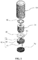
- FIG. 2 is an exploded perspective view illustrating the embodiment shown in FIG. 1 ;
- FIG. 3 is a conceptual diagram illustrating an ampoule part of the embodiment shown in FIG. 1 ;
- FIG. 4 is a conceptual diagram illustrating a percussion pin of the embodiment shown in FIG. 1 .
- FIGS. 1 to 4 One embodiment of an ampoule-type reserve battery according to the present invention will be described with reference to FIGS. 1 to 4 .
- the ampoule-type reserve battery includes a housing 10 , an ampoule part 20 , a fixing part 30 , an electrode 40 , a percussion pin 50 , an absorption part 60 , and a sealing part 70 .
- the housing 10 has an open lower portion and accommodates the ampoule part 20 , the fixing part 30 , the electrode 40 , the percussion pin 50 , and the absorption part 60 therein.
- the ampoule part 20 serves to store an electrolyte 25 therein.
- the ampoule part 20 includes an ampoule casing 21 , the electrolyte 25 , a leakage prevention liquid 27 , and a separation membrane 29 .
- the ampoule casing 21 includes a first case 22 , a stopper 23 , and a second case 24 and accommodates the electrolyte 25 and the leakage prevention liquid 27 .
- an accommodation part 22 a is formed therein, and thus the electrolyte 25 is accommodated in a lower portion of the accommodation part 22 a , the leakage prevention liquid 27 is accommodated in an upper portion of accommodation part 22 a , and the upper portion thereof is open.
- the stopper 23 serves to prevent the leakage prevention liquid 27 accommodated in the upper portion of the accommodation part 22 a from leaking through an upper portion of the first case 22 . To this end, the stopper 23 is mounted on the upper portion of the first case 22 .
- the fixing part 30 is coupled to an upper end 24 a , a lower end of the second case 24 is open, and the first case 22 is inserted and coupled to the second case 24 .
- the second case 24 is screw-coupled to the first case 22 or is coupled thereto using an adhesive.
- the electrolyte 25 is accommodated in the lower portion of the accommodation part 22 a of the first case 22 and transferred to the electrode 40 to allow a current to flow.
- the leakage prevention liquid 27 serves to prevent the electrolyte 25 from leaking through the upper portion of the accommodation part 22 a .
- the leakage prevention liquid 27 is made of oil, which is phase-separated from the electrolyte 25 without being mixed therewith, and accommodated in the upper portion of the accommodation part 22 a . Since the reserve battery is stored at a temperature ranging from ⁇ 54° C. to 63° C., oil of which a chemical property is not changed in such temperature conditions should also be used as the leakage prevention liquid 27 . In addition, when the leakage prevention liquid 27 is mixed with the electrolyte 25 , the electrolyte 25 is diluted.
- oil which is phase-separated from the electrolyte 25 should be used as the leakage prevention liquid 27 .
- the electrolyte 25 may leak through a gap between the first case 22 and the second case 24 which are screw-coupled. Even when the first case 22 and the second case 24 are coupled using an adhesive, since the adhesive melts in the acid-based electrolyte 25 , the electrolyte 25 leaks to the outside so that it is difficult to store the electrolyte 25 in the first case 22 for a long period of time.
- the leakage prevention liquid 27 may serve as a sealing to prevent leakage of the electrolyte 25 , thereby allowing the electrolyte 25 to be stored for a long period of time.
- the separation membrane 29 may be mounted in the accommodation part 22 a of the first case 22 so as to separate the electrolyte 25 from the leakage prevention liquid 27 .
- the fixing part 30 is coupled to the upper end 24 a of the second case 24 to fix the second case 24 to an upper side of an interior of the housing 10 .
- the fixing part 30 is fixed such that, when an impact is applied to the housing 10 , the ampoule part 20 falls in the interior of the housing 10 .
- the fixing part 30 is formed of an elastic spring to press the upper end 24 a of the second case 24 and the upper side of the housing 10 .
- the electrode 40 includes a substrate 41 , a cathode 43 , and an anode 45 and is mounted to be spaced a predetermined interval from the ampoule part 20 on a lower side of the interior of the housing 10 .
- the electrode 40 electrochemically reacts with the electrolyte 25 to be activated, thereby generating electricity.
- the percussion pin 50 may be mounted on the substrate 41 so as to strike and destroy the ampoule casing 21 when the ampoule part 20 falls.
- one end 50 a of the percussion pin 50 is exposed at an upper end of the electrode 40 .
- a groove 51 is formed in a length direction in the one end 50 a to allow the electrolyte 25 accommodated in the lower portion of the accommodation part 22 a to flow to the absorption part 60 when a lower portion of the first case 22 of the ampoule casing 21 is destroyed.
- a plurality of grooves 51 are formed at regular intervals in a circumferential direction so as to allow the electrolyte 25 to be sufficiently transferred to the absorption part 60 . Meanwhile, in the percussion pin 50 , an end portion of the one end 50 a may be formed to be sharp so as to strike and pass through the lower portion of the first case 22 of the ampoule casing 21 .
- the absorption part 60 is disposed on an upper end of the electrode 40 to absorb the electrolyte 25 .
- the sealing part 70 serves to seal the housing 10 . To this end, the sealing part 70 is mounted in a lower portion of the housing 10 .
- the fixing part 30 is coupled to the upper end 24 a of the second case 24 , and thus the ampoule part 20 accommodating the electrolyte 25 is fixed to the upper side of the interior of the housing 10 .
- the ampoule part 20 is spaced a predetermined interval from the electrode 40 mounted on the lower side of the interior of the housing 10 to be fixed to the upper side of the interior of the housing 10 .
- the reserve battery is used and an impact is applied to the housing 10
- the upper end 24 a of the second case 24 is separated from the fixing part 30 to fall.
- the percussion pin 50 strikes and destroys the lower portion of the first case 22 .
- the electrolyte 25 flows downward toward the absorption part 60 along the groove 51 of the percussion pin 50 .
- the electrolyte 25 may be sufficiently absorbed into the absorption part 60 along the groove 51 .
- the electrolyte 25 flowing out is absorbed by the absorption part 60 and is uniformly transferred to the cathode 43 and the anode 45 of the electrode 40 and, simultaneously, electricity is generated.
- the absorption part 60 is disposed at the upper end of the electrode 40 and transfers the electrolyte 25 to the electrode 40 such that the electrolyte 25 and the electrode 40 may react for a long period of time and also an amount of the electrolyte 25 required for a chemical reaction may be minimized.
- the conventional reserve battery is configured such that a push plate moved due to a percussion device destroys a lower surface of an electrolyte storage part in which an electrolyte is stored, and thus the electrolyte is introduced into a lower side of an exterior part to react with an electrode.
- the electrolyte cannot be completely sealed because, when percussed, the push plate or a separation membrane is pushed and inserted into the electrolyte storage part and thus the electrolyte flows out so that there is a problem in that the conventional reserve battery cannot be stored for a long period of time.
- the electrolyte 25 is accommodated in the lower portion of the ampoule casing 21
- the leakage prevention liquid 27 is accommodated in the upper portion of the ampoule casing 21 .
- the leakage prevention liquid 27 is made of oil which is phase-separated from the electrolyte 25 without being mixed therewith such that it is possible to prevent the electrolyte 25 from leaking through the upper portion of the ampoule casing 21 .
- the reserve battery may be stored for a long period of time and used.
- the groove 51 is formed at one end of the percussion pin 50 in the length direction so as to allow the electrolyte 25 accommodated in the an casing 21 to flow to the absorption part 60 when the percussion pin 50 strikes and destroys the ampoule casing 21 .
- the electrolyte 25 may be sufficiently absorbed into the absorption part 60 along the groove 51 .
- an electrolyte is accommodated in a lower portion of an ampoule casing and a leakage prevention liquid is accommodated in an upper portion of the ampoule casing.
- the leakage prevention liquid is made of oil which is phase-separated from the electrolyte without being mixed therewith such that the electrolyte can be prevented from leaking through the upper portion of the ampoule casing. Consequently, a reserve battery can be stored for a long period of time and used.
- a groove is formed at one end of a percussion pin in a length direction so as to allow the electrolyte accommodated in the ampoule casing to flow to an absorption part when the percussion pin strikes and destroys the ampoule casing.
- the electrolyte can be sufficiently absorbed into the absorption part along the groove.
Landscapes
- Chemical & Material Sciences (AREA)
- Chemical Kinetics & Catalysis (AREA)
- Electrochemistry (AREA)
- General Chemical & Material Sciences (AREA)
- Engineering & Computer Science (AREA)
- Manufacturing & Machinery (AREA)
- Filling, Topping-Up Batteries (AREA)
Abstract
Description
Claims (4)
Applications Claiming Priority (2)
| Application Number | Priority Date | Filing Date | Title |
|---|---|---|---|
| KR10-2020-0090136 | 2020-07-21 | ||
| KR1020200090136A KR102371966B1 (en) | 2020-07-21 | 2020-07-21 | Reserve battery |
Publications (2)
| Publication Number | Publication Date |
|---|---|
| US20220029142A1 US20220029142A1 (en) | 2022-01-27 |
| US11296331B2 true US11296331B2 (en) | 2022-04-05 |
Family
ID=79728791
Family Applications (1)
| Application Number | Title | Priority Date | Filing Date |
|---|---|---|---|
| US17/080,744 Expired - Fee Related US11296331B2 (en) | 2020-07-21 | 2020-10-26 | Ampoule-type reserve battery |
Country Status (3)
| Country | Link |
|---|---|
| US (1) | US11296331B2 (en) |
| KR (1) | KR102371966B1 (en) |
| WO (1) | WO2022019367A1 (en) |
Families Citing this family (1)
| Publication number | Priority date | Publication date | Assignee | Title |
|---|---|---|---|---|
| JP1693374S (en) * | 2020-12-23 | 2021-08-23 |
Citations (3)
| Publication number | Priority date | Publication date | Assignee | Title |
|---|---|---|---|---|
| KR20110017636A (en) | 2009-08-14 | 2011-02-22 | 세주엔지니어링주식회사 | Electrode structure of reserve battery and reserve battery |
| KR20140065861A (en) | 2012-11-22 | 2014-05-30 | 세주엔지니어링주식회사 | High safety a large output reserve battery |
| KR101485897B1 (en) | 2013-10-29 | 2015-01-26 | 주식회사 비츠로셀 | reserve battery enhancing impact resistant |
Family Cites Families (4)
| Publication number | Priority date | Publication date | Assignee | Title |
|---|---|---|---|---|
| EP0026606B1 (en) * | 1979-09-24 | 1984-07-25 | The Secretary of State for Defence in Her Britannic Majesty's Government of the United Kingdom of Great Britain and | Battery initiator system |
| US4968567A (en) * | 1989-07-31 | 1990-11-06 | Honeywell Inc. | Reserve activated electrochemical cell with a cell condition checking apparatus |
| KR101637224B1 (en) * | 2014-11-03 | 2016-07-07 | 주식회사 비츠로셀 | header of battery with structure for perventing leakage and crack |
| KR20180105317A (en) * | 2017-03-15 | 2018-09-28 | 주식회사 비츠로셀 | Reserve battery with improvement in efficiency of electrolyte impregnation |
-
2020
- 2020-07-21 KR KR1020200090136A patent/KR102371966B1/en not_active Expired - Fee Related
- 2020-08-04 WO PCT/KR2020/010263 patent/WO2022019367A1/en not_active Ceased
- 2020-10-26 US US17/080,744 patent/US11296331B2/en not_active Expired - Fee Related
Patent Citations (3)
| Publication number | Priority date | Publication date | Assignee | Title |
|---|---|---|---|---|
| KR20110017636A (en) | 2009-08-14 | 2011-02-22 | 세주엔지니어링주식회사 | Electrode structure of reserve battery and reserve battery |
| KR20140065861A (en) | 2012-11-22 | 2014-05-30 | 세주엔지니어링주식회사 | High safety a large output reserve battery |
| KR101485897B1 (en) | 2013-10-29 | 2015-01-26 | 주식회사 비츠로셀 | reserve battery enhancing impact resistant |
Also Published As
| Publication number | Publication date |
|---|---|
| WO2022019367A1 (en) | 2022-01-27 |
| KR20220011353A (en) | 2022-01-28 |
| US20220029142A1 (en) | 2022-01-27 |
| KR102371966B1 (en) | 2022-03-07 |
Similar Documents
| Publication | Publication Date | Title |
|---|---|---|
| US20220029142A1 (en) | Ampoule-type reserve battery | |
| ATE367654T1 (en) | ALKALINE FUEL CELL WITH FLAT CASE | |
| JPH02500766A (en) | A device for continuously supplying liquid or viscous media, especially lubricating substances | |
| US6844108B1 (en) | Ultraminiaturized reserve battery cell | |
| JP2015230756A (en) | Secondary battery | |
| KR101105268B1 (en) | Electrode structure of reserve battery and reserve battery | |
| JP3612931B2 (en) | Cylindrical alkaline battery | |
| KR20200087984A (en) | Cylindrical Secondary Battery Having Open and Close Part | |
| KR20230032124A (en) | Reserve battery | |
| KR100982635B1 (en) | Fuel container | |
| KR101485897B1 (en) | reserve battery enhancing impact resistant | |
| US20050255361A1 (en) | Connecting structure and connecting method of fuel cell | |
| US3827914A (en) | Activator for a reserve electric cell,as in a flashlight | |
| JP2005203175A (en) | Jointing device for supplying and receiving liquid | |
| KR100758241B1 (en) | Storage structure | |
| KR102698661B1 (en) | Secondary battery that can improve long term characteristics and manufacturing method thereof | |
| JP2018101480A (en) | Fuel cell stack | |
| KR20120022331A (en) | An impact-type reserve-battery cell | |
| US20060210844A1 (en) | Fuel tank and cap device thereof | |
| US7011906B2 (en) | Battery for an electrical appliance that consumes low voltage battery | |
| JP4565862B2 (en) | Electrolyte supply method | |
| US12355112B2 (en) | Reserve battery with fast voltage rise time | |
| KR100842228B1 (en) | Fluid Regulator System for Fuel Cell | |
| KR0130858Y1 (en) | Gasket for Lithium Primary Battery | |
| WO2009154069A1 (en) | Fuel filling kit and fuel filling method |
Legal Events
| Date | Code | Title | Description |
|---|---|---|---|
| AS | Assignment |
Owner name: TAEYOUNG INDUSTRY CORP., KOREA, REPUBLIC OF Free format text: ASSIGNMENT OF ASSIGNORS INTEREST;ASSIGNORS:LEE, NAM HOON;KO, YOUNG MIN;REEL/FRAME:054170/0572 Effective date: 20201005 |
|
| FEPP | Fee payment procedure |
Free format text: ENTITY STATUS SET TO UNDISCOUNTED (ORIGINAL EVENT CODE: BIG.); ENTITY STATUS OF PATENT OWNER: MICROENTITY |
|
| FEPP | Fee payment procedure |
Free format text: ENTITY STATUS SET TO MICRO (ORIGINAL EVENT CODE: MICR); ENTITY STATUS OF PATENT OWNER: MICROENTITY |
|
| STPP | Information on status: patent application and granting procedure in general |
Free format text: PUBLICATIONS -- ISSUE FEE PAYMENT VERIFIED |
|
| STCF | Information on status: patent grant |
Free format text: PATENTED CASE |
|
| FEPP | Fee payment procedure |
Free format text: MAINTENANCE FEE REMINDER MAILED (ORIGINAL EVENT CODE: REM.); ENTITY STATUS OF PATENT OWNER: MICROENTITY |
|
| LAPS | Lapse for failure to pay maintenance fees |
Free format text: PATENT EXPIRED FOR FAILURE TO PAY MAINTENANCE FEES (ORIGINAL EVENT CODE: EXP.); ENTITY STATUS OF PATENT OWNER: MICROENTITY |
|
| STCH | Information on status: patent discontinuation |
Free format text: PATENT EXPIRED DUE TO NONPAYMENT OF MAINTENANCE FEES UNDER 37 CFR 1.362 |
|
| FP | Lapsed due to failure to pay maintenance fee |
Effective date: 20260405 |