US11295133B2 - Interaction display method and interaction display system - Google Patents
Interaction display method and interaction display system Download PDFInfo
- Publication number
- US11295133B2 US11295133B2 US16/680,497 US201916680497A US11295133B2 US 11295133 B2 US11295133 B2 US 11295133B2 US 201916680497 A US201916680497 A US 201916680497A US 11295133 B2 US11295133 B2 US 11295133B2
- Authority
- US
- United States
- Prior art keywords
- operator
- feature
- global
- pairing
- features
- Prior art date
- Legal status (The legal status is an assumption and is not a legal conclusion. Google has not performed a legal analysis and makes no representation as to the accuracy of the status listed.)
- Active
Links
Images


Classifications
-
- G06K9/00671—
-
- G—PHYSICS
- G06—COMPUTING OR CALCULATING; COUNTING
- G06F—ELECTRIC DIGITAL DATA PROCESSING
- G06F3/00—Input arrangements for transferring data to be processed into a form capable of being handled by the computer; Output arrangements for transferring data from processing unit to output unit, e.g. interface arrangements
- G06F3/01—Input arrangements or combined input and output arrangements for interaction between user and computer
- G06F3/011—Arrangements for interaction with the human body, e.g. for user immersion in virtual reality
- G06F3/013—Eye tracking input arrangements
-
- G—PHYSICS
- G06—COMPUTING OR CALCULATING; COUNTING
- G06F—ELECTRIC DIGITAL DATA PROCESSING
- G06F3/00—Input arrangements for transferring data to be processed into a form capable of being handled by the computer; Output arrangements for transferring data from processing unit to output unit, e.g. interface arrangements
- G06F3/01—Input arrangements or combined input and output arrangements for interaction between user and computer
- G06F3/017—Gesture based interaction, e.g. based on a set of recognized hand gestures
-
- G—PHYSICS
- G06—COMPUTING OR CALCULATING; COUNTING
- G06F—ELECTRIC DIGITAL DATA PROCESSING
- G06F3/00—Input arrangements for transferring data to be processed into a form capable of being handled by the computer; Output arrangements for transferring data from processing unit to output unit, e.g. interface arrangements
- G06F3/01—Input arrangements or combined input and output arrangements for interaction between user and computer
- G06F3/03—Arrangements for converting the position or the displacement of a member into a coded form
- G06F3/041—Digitisers, e.g. for touch screens or touch pads, characterised by the transducing means
- G06F3/042—Digitisers, e.g. for touch screens or touch pads, characterised by the transducing means by opto-electronic means
-
- G—PHYSICS
- G06—COMPUTING OR CALCULATING; COUNTING
- G06F—ELECTRIC DIGITAL DATA PROCESSING
- G06F3/00—Input arrangements for transferring data to be processed into a form capable of being handled by the computer; Output arrangements for transferring data from processing unit to output unit, e.g. interface arrangements
- G06F3/01—Input arrangements or combined input and output arrangements for interaction between user and computer
- G06F3/048—Interaction techniques based on graphical user interfaces [GUI]
- G06F3/0487—Interaction techniques based on graphical user interfaces [GUI] using specific features provided by the input device, e.g. functions controlled by the rotation of a mouse with dual sensing arrangements, or of the nature of the input device, e.g. tap gestures based on pressure sensed by a digitiser
- G06F3/0488—Interaction techniques based on graphical user interfaces [GUI] using specific features provided by the input device, e.g. functions controlled by the rotation of a mouse with dual sensing arrangements, or of the nature of the input device, e.g. tap gestures based on pressure sensed by a digitiser using a touch-screen or digitiser, e.g. input of commands through traced gestures
- G06F3/04883—Interaction techniques based on graphical user interfaces [GUI] using specific features provided by the input device, e.g. functions controlled by the rotation of a mouse with dual sensing arrangements, or of the nature of the input device, e.g. tap gestures based on pressure sensed by a digitiser using a touch-screen or digitiser, e.g. input of commands through traced gestures for inputting data by handwriting, e.g. gesture or text
-
- G06K9/4671—
-
- G—PHYSICS
- G06—COMPUTING OR CALCULATING; COUNTING
- G06V—IMAGE OR VIDEO RECOGNITION OR UNDERSTANDING
- G06V20/00—Scenes; Scene-specific elements
- G06V20/20—Scenes; Scene-specific elements in augmented reality scenes
-
- G—PHYSICS
- G06—COMPUTING OR CALCULATING; COUNTING
- G06V—IMAGE OR VIDEO RECOGNITION OR UNDERSTANDING
- G06V40/00—Recognition of biometric, human-related or animal-related patterns in image or video data
- G06V40/10—Human or animal bodies, e.g. vehicle occupants or pedestrians; Body parts, e.g. hands
- G06V40/107—Static hand or arm
-
- G—PHYSICS
- G06—COMPUTING OR CALCULATING; COUNTING
- G06F—ELECTRIC DIGITAL DATA PROCESSING
- G06F2203/00—Indexing scheme relating to G06F3/00 - G06F3/048
- G06F2203/038—Indexing scheme relating to G06F3/038
- G06F2203/0381—Multimodal input, i.e. interface arrangements enabling the user to issue commands by simultaneous use of input devices of different nature, e.g. voice plus gesture on digitizer
-
- G06K2209/21—
-
- G—PHYSICS
- G06—COMPUTING OR CALCULATING; COUNTING
- G06V—IMAGE OR VIDEO RECOGNITION OR UNDERSTANDING
- G06V2201/00—Indexing scheme relating to image or video recognition or understanding
- G06V2201/07—Target detection
-
- G—PHYSICS
- G06—COMPUTING OR CALCULATING; COUNTING
- G06V—IMAGE OR VIDEO RECOGNITION OR UNDERSTANDING
- G06V40/00—Recognition of biometric, human-related or animal-related patterns in image or video data
- G06V40/10—Human or animal bodies, e.g. vehicle occupants or pedestrians; Body parts, e.g. hands
- G06V40/18—Eye characteristics, e.g. of the iris
Definitions
- the disclosure relates to an interaction display method and an interaction display system.
- a transparent display may be including a transmissive transparent display and/or a projection transparent display.
- the transparent display has the characteristics of transparency, lightness, and thinness, which may combine a virtual image displayed on the display with a scene of the real world, giving the user an intuitive visual experience.
- the transparent display may be widely used in applications such as car head-up displays, vending machines, merchandise windows, museum exhibits, sightseeing vehicle tours, etc. Viewers not only may see a real object through the transparent display, but also may see the information superimposed on or displayed around the transparent display, and even interact, through a biometric tracking technique or a touch technique, with information displayed on the transparent display.
- an interaction display system may combine a plurality of human features or touch points to identify user interaction intentions, thereby providing display information that meets user expectations.
- the interaction display system may detect many human features and many touch points, but the interaction display system may not correctly pair these human features or touch points, causing the interaction display system to be prone to directivity confusion.
- the human body features and touch points of the same user are correctly paired may the user's pointing direction be correctly estimated to provide display content that meets the user's expectations. For example, FIG.
- FIG. 1 is a schematic diagram of interaction between a transparent display 10 and a plurality of users. If the interaction display system pairs an eye feature E 1 of a user A 1 to a touch point T 1 given by another user B 1 to a display plane S 1 , the interaction display system generates an incorrect pointing direction V 1 .
- the interaction display system displays object information (i.e., a caterpillar) of a target object Obj 1 behind the transparent display 10 according to the incorrect pointing direction V 1 , and may not display, according to a correct pointing direction V 2 , object information of a target object Obj 2 that meets the user A 1 's expectations.
- object information i.e., a caterpillar
- An embodiment of the disclosure provides an interaction display method adapted for an interaction display system including a transparent display, at least one image sensing device, and a processing device.
- the interaction display method includes the following steps. An image data of a plurality of operators is captured by the image sensing device.
- the processing device performs the following steps. At least one local feature and at least one global feature of the operators are extracted from the image data, and at least one projection point on a display plane of the transparent display is detected, wherein the projection point is generated in response to an interactive behavior of the operators.
- Each of the local features and each of the global features are paired.
- Each of the projection points and each of the global features are paired.
- a pointing direction of one of the operators is determined according to a pairing result between each of the local features and each of the global features and a pairing result between each of the projection points and each of the global features.
- An embodiment of the disclosure provides an interaction display system, including a transparent display, at least one image sensing device, and a processing device.
- the processing device is coupled to the transparent display and the image sensing device.
- the image sensing device captures an image data of a plurality of operators.
- the processing device is configured to perform the following steps. At least one local feature and at least one global feature of the operators are extracted from the image data and at least one projection point on a display plane of the transparent display is detected, wherein the projection point is generated in response to an interactive behavior of the operators.
- Each of the local features and each of the global features are paired.
- Each of the projection points and each of the global features are paired.
- a pointing direction of one of the operators is determined according to a pairing result between each of the local features and each of the global features and a pairing result between each of the projection points and each of the global features.
- FIG. 1 is a schematic diagram of interaction between a conventional transparent display and a plurality of users.
- FIG. 2 is a schematic diagram of an interaction display system according to an embodiment of the disclosure.
- FIG. 3A is a flowchart of an interaction display method according to an embodiment of the disclosure.
- FIG. 3B is a schematic diagram of a scenario in which a transparent display interacts with a plurality of users according to an embodiment of the disclosure.
- FIG. 4 is a flowchart of an interaction display method according to an embodiment of the disclosure.
- FIG. 5 is a flowchart of an interaction display method according to an embodiment of the disclosure.
- FIG. 6A is a flowchart of an interaction display method according to an embodiment of the disclosure.
- FIG. 6B is a schematic diagram of a scenario of an interaction display method according to an embodiment of the disclosure.
- FIG. 7A is a flowchart of an interaction display method according to an embodiment of the disclosure.
- FIG. 7B is a schematic diagram of a scenario of an interaction display method according to an embodiment of the disclosure.
- FIG. 8A is a flowchart of an interaction display method according to an embodiment of the disclosure.
- FIG. 8B is a schematic diagram of a scenario of an interaction display method according to an embodiment of the disclosure.
- FIG. 9A is a flowchart of an interaction display method according to an embodiment of the disclosure.
- FIG. 9B is a schematic diagram of a scenario of an interaction display method according to an embodiment of the disclosure.
- FIG. 10A is a flowchart of an interaction display method according to an embodiment of the disclosure.
- FIG. 10B is a schematic diagram of a scenario of an interaction display method according to an embodiment of the disclosure.
- FIG. 11 is a flowchart of an interaction display method according to an embodiment of the disclosure.
- a transparent display may display, according to a correct pointing direction, display content that meets the operator's intention.
- the operator's notification information (for example, suggestion for a moving location, notification of a missing feature, and notification of an identifiable or an unidentifiable operator identification code (User ID), etc.) may be provided to improve a success rate and accuracy of feature detection and pairing of a plurality of interaction intention information.
- a pointing direction may also be determined according to the remaining available interaction intention information, so as to continue the interaction for use.
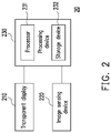
- FIG. 2 is a schematic diagram of an interaction display system according to an embodiment of the disclosure.
- an interaction display system 20 includes a transparent display 210 , at least one image sensing device 220 , and a processing device 230 .
- the processing device 230 may be coupled to the transparent display 210 and the image sensing device 220 .
- the interaction display system 20 may interact with a plurality of operators. Furthermore, the interaction display system 20 may determine pointing directions of the plurality of operators, and provide corresponding display effects and content accordingly.
- the operators may be robots, robotic arms, machine tools, or human users, which is not limited in the disclosure.
- the transparent display 210 is a display or a floating projection device having a certain degree of light transmittance, for example, a thin film transistor liquid crystal display (TFT-LCD), a field sequential color display, an active matrix organic light emitting display (AMOLED), a transmission transparent display such as an electrowetting display, or a transparent projection display, which may present a view of the display relative to the other side of the user when being viewed by a human user.
- TFT-LCD thin film transistor liquid crystal display
- AMOLED active matrix organic light emitting display
- AMOLED active matrix organic light emitting display
- a transmission transparent display such as an electrowetting display
- a transparent projection display which may present a view of the display relative to the other side of the user when being viewed by a human user.
- the transparent display 210 may also be combined with the touch panel to receive interaction of the user from direct contact, or be combined with a sensor that may detect a click and gesture trigger, for example, sensing a hand trigger action through a sound wave, an infrared light, or an image to provide an interaction display function based on the trigger action.
- a click and gesture trigger for example, sensing a hand trigger action through a sound wave, an infrared light, or an image to provide an interaction display function based on the trigger action.
- the image sensing device 220 may capture an image data of a plurality of operators located on one side of the transparent display 210 .
- the image sensing device 220 may be configured as a plurality of sets of image sensing devices to expand the field of view of the photographic features and combine a plurality of sets of detection images.
- the image sensing device 220 may capture the image data of the plurality of operators according to an infrared light sensing technique, a natural light sensing technique, an ultrasonic sensing technique, a laser sensing technique, or the like, which is not limited in the disclosure.
- the image sensing device 220 may be an image sensing device such as an eye tracker, a depth camera, a color camera, a stereo camera, or the like.
- FIG. 2 is an example of an image sensing device 220 for description. In other embodiments, there may be one or more image sensing devices, which is not limited in the disclosure.
- the processing device 230 includes one or more processors (a processor 231 as an example for description below) and one or more storage devices (a storage device 232 as an example for description below).
- the processing device 230 may be implemented by a computer host, a server, or a computer device with data computing capabilities.
- the processing device 230 may be implemented by one or more electronic devices, which is not limited in the disclosure.
- the processor 231 is, for example, a central processing unit (CPU) or other programmable general-purpose or special-purpose microprocessors, a digital signal processor (DSP), a programmable controller, an application-specific integrated circuit (ASIC), a programmable logic device (PLD), or other similar devices, or a combination of these devices.
- the processor 231 is configured to execute a command or a program recorded by the storage device 232 .
- the processor 231 is configured to perform an operation on operator feature extraction, pairing between local features and global features, and pairing between projection points and global features.
- the processor 231 may determine pointing direction information of the operator according to the pairing result, and determine the display content according to the pointing direction information. If an operator's local features, global features, or projection points are missing, the processor 231 is configured to perform an interaction continuation operation to generate continuous pointing direction information, and may be configured to provide notification information to the user.
- the storage device 232 may be any type of fixed or removable random-access memory (RAM), a read-only memory (ROM), a flash memory, or a similar element, or a combination of the foregoing elements.
- the storage device 232 is configured to store an image data captured by the image sensing device 220 and record programs or commands that are accessible and executable by the processor 231 .
- the storage device 232 may be configured to store image extraction feature information and operator feature database for operation query.
- FIG. 3A is a flowchart of an interaction display method according to an embodiment of the disclosure.
- the method process in FIG. 3A may be implemented in combination with the interaction display system 20 shown in FIG. 2 . Refer to FIG. 2 and FIG. 3A together.
- an image sensing device 220 captures an image data of a plurality of operators (Step S 310 ).
- the image data may include color images, depth images, infrared sensing images, ultrasound images, or laser images, etc.
- the image data may include a plurality of images with different image capturing ranges.
- the image data may include a local image data for capturing a local part of the operator, such as a facial image, a hand image, or a local image data captured for a handheld object.
- the foregoing handheld device is, for example, a remote-control object or a remote-control electronic device for interacting with the transparent display 210 .
- the image data may further include a global image data for capturing the operator's overall image, such as a global image data covering part of the body or a whole body of the operator.
- the processing device 230 extracts at least one local feature and at least one global feature of the operators from the image data, and detects at least one projection point on a display plane of the transparent display 210 (step S 320 ).
- the processing device 230 may extract at least one local feature and at least one global feature of the operators from the image data.
- the local features are features with operator interaction intentions, for example, eye features, line of sight features, part features of a robot, or totem features on a handheld object, etc.
- the global features are features that may indicate features of the operator's manipulation gestures, for example, limb features, skeleton features, gesture features, and the like.
- the projection points on the display plane are generated in response to an interactive behaviour of the operators, and the interactive behaviour of the operators includes a touch behaviour of actually touching the display plane or a floating pointing behaviour of not actually touching the display plane.
- the projection points on the display plane are, for example, touch points detected by the transparent display 210 , or may be floating pointing projection points estimated based on an image analysis technique, a biometric feature sensing technique, or a somatosensory detection technique.
- the processing device 230 pairs each of the local features and each of the global features (step S 330 ). Further, the processing device 230 pairs each of the projection points and each of the global features (step S 340 ). Step S 330 and step S 340 may also be alternately performed, between which there is no sequential relationship. In other words, the processing device 230 determines whether the local features may be paired with the global features one by one to obtain a paired connection relationship between the local features and the global features. Similarly, the processing device 230 determines whether the projection points may be paired with the global features one by one to obtain a paired connection relationship between the projection points and the global features.
- the processing device 230 may obtain both a planar coordinate location of the local features relative to an image coordinate system and a planar coordinate location of the global features relative to the image coordinate system.
- the processing device 230 may simultaneously obtain a plane coordinate location of the projection points relative to a screen coordinate system.
- the processing device 230 may perform coordinate system transformation fusion to obtain local features, global features, and a spatial coordinate location of the projection points relative to a same reference coordinate system.
- the processing device 230 may pair each of the local features and each of the global features according to the spatial coordinate location of the local features relative to the reference coordinate system and the spatial coordinate location of the global features relative to the reference coordinate system.
- the processing device 230 may pair each of the projection points and each of the global features according to the spatial coordinate location of the projection points relative to the reference coordinate system and the spatial coordinate location of the global features relative to the reference coordinate system.
- the local features as the eye features and the global features as the limb features are used herein as examples.
- the processing device 230 may pair the eye features as the local features with the limb features as the global features, thereby pairing the local features with the global features that belong to the same operator.
- the processing device 230 may determine whether a distance between the spatial coordinate location of the local features and the spatial coordinate location of the global features is within a threshold range of the global features corresponding to the local features in a feature database to determine whether to pair the local features and the global features. For example, a range of the head features (that is, global features) extracted from the image is converted to a common space with a projection size of 10-15 cm. Although varying from person to person, the location of the eye features (that is, local features) is also within the head range. An area within ⁇ 8 cm of the center point of the head features may be set as an eye pairing area accordingly.
- the projection points as the touch points and the global features as the limb features are used herein as examples.
- the touch points are generated because the hand touches the display plane, and therefore, there is an association between the spatial coordinate location of the projection points and the spatial coordinate location of the hand features in the limb features.
- the processing device 230 detects, using global images, that the operator performs a touch operation at a location of 7 cm in a lateral direction of the touch panel, and detects a total of 15 cm of the touch panel.
- the touch panel detects that the operator's touch operation occurs at a touch location of 7 cm in the lateral direction of the panel, and therefore, the processing device 230 may pair the operator's global features with the touch point.
- the processing device 230 may pair the touch point as the projection points with the limb features as the global features, thereby pairing the projection points with the global features that belong to the same operator.
- the processing device 230 may determine whether the spatial coordinate location of the touch point is close enough to the spatial coordinate location of the hand features to determine whether to pair the projection points with the global features.
- the processing device 230 may determine a pointing direction of one of the operators according to a pairing result between each of the local features and each of the global features and a pairing result between each of the projection points and each of the global features.
- the processing device 230 in response to successful pairing between a first local feature of the local features and a first global feature of the global features via location or image feature information and successful pairing between a first projection point of the projection points and the first global feature via the location or image feature information, the processing device 230 determines a first pointing direction of one of the operators according to the first local feature and the first projection point to display interaction information according to the first pointing direction through the transparent display 210 (step S 350 ).
- the processing device 230 may determine a target object with the first pointing direction to a rear of the transparent display 210 , thereby driving the transparent display 210 to display object information of the target object.
- the first local feature is successfully paired to the first global feature, indicating that the first local feature may be in one-to-one pairing to the first global feature.
- the first projection point is successfully paired to the first global feature, indicating that the first projection point may be in one-to-one pairing to the first global feature. It should be noted that because there are associations between the global features and the local features and the projection points, the local features and the projection points may be successively paired to the global features.
- the local features and projection points successfully paired to the same global feature may be determined to correspond to the same operator, and a correct pointing direction is generated according to the local features and projection points belonging to the same operator, thereby avoiding an incorrect pointing direction caused by an interaction intention information pairing error.
- FIG. 3B is a schematic diagram of a scenario according to an embodiment of the disclosure.
- a processing device 230 may obtain eye features EU 1 and EU 2 and limb features BU 1 and BU 2 from the image data.
- the processing device 230 may obtain a touch point TU 1 and a touch point TU 2 according to touch detection by the transparent display 210 .
- the processing device 230 may pair the eye feature EU 1 and the limb feature BU 1 according to a spatial coordinate location of the eye feature EU 1 and a spatial coordinate location of a head feature HU 1 in the limb feature BU 1 .
- the processing device 230 may pair the touch point TU 1 and the limb feature BU 1 according to a spatial coordinate location of the touch point TU 1 and a spatial coordinate location of a hand feature GU 1 in the limb feature BU 1 . Therefore, the processing device 230 may obtain correspondence between the eye feature EU 1 and the touch point TU 1 , thereby generating a pointing direction DF 1 of the user U 1 according to the eye feature EU 1 and the touch point TU 1 .
- the transparent display 210 may display, according to the pointing direction DF 1 , interaction information in conformity with the interaction intention. It may be seen that the processing device 230 may avoid incorrect pointing information as a result of pairing the eye features belonging to different users with the touch points.
- the processing device 230 may obtain the correspondence between the eye feature EU 2 and the touch point TU 2 using the hand feature GU 2 and the head feature HU 2 in the limb feature BU 2 , thereby generating a pointing direction DF 2 of the user U 2 according to the eye feature EU 2 and the touch point TU 2 .
- the transparent display 210 displays interaction information to the users U 1 and U 2 based on the pointing directions DF 1 and DF 2 .
- the processing device 230 may further determine whether the first pointing direction passes through a display plane of the transparent display 210 to determine whether to display the interaction information according to the first pointing direction. In other words, when the first pointing direction passes through the display range of the transparent display 210 , the processing device 230 may provide interaction information to the operators. Otherwise, when the first pointing direction does not pass through the display range of the transparent display 210 , the processing device 230 does not provide interaction information to the operators.
- FIG. 4 is a flowchart of an interaction display method according to an embodiment of the disclosure.
- the method process in FIG. 4 may be implemented in combination with the interaction display system 20 shown in FIG. 2 .
- Steps S 410 to S 450 are similar to steps S 310 to S 350 of the foregoing embodiment, so the descriptions thereof are omitted herein.
- the processing device 230 determines whether the first pointing direction passes through a display plane of the transparent display 210 (step S 460 ).
- the first pointing direction is vector information, and therefore the processing device 230 may determine whether the first pointing direction passes through a plane (that is, a display plane) with a specific size in space. If the first pointing direction passes through the display plane of the transparent display 210 , the processing device 230 displays the interaction information according to the first pointing direction through the transparent display 210 (step S 470 ). As shown in FIG.
- the processing device 230 may determine that the first pointing direction DF 1 passes through a display plane S 2 of the transparent display 210 , and displays the interaction information according to the first pointing direction DF 1 through the transparent display 210 . According to another aspect, if the first pointing direction does not pass through the display plane of the transparent display 210 , the processing device 230 disables the transparent display 210 to display the interaction information according to the first pointing direction (step S 480 ).
- the processing device 230 may generate notification information for the operators, for example, suggestion for a moving location, notification of a missing feature, an identifiable or an unidentifiable user ID, etc., and the transparent display 210 displays the notification information. Therefore, if the operators may correctly correct the location according to the notification information, the processing device 230 may obtain the local features, global features, or projection points that were originally missing in the past, thereby improving the pairing success rate of the local features, the global features, and the projection points.
- the processing device 230 may determine an appropriate pointing direction according to available local features that are unsuccessfully paired, global features, or projection points, so that the operators continue to interact with the interaction display system 20 .
- FIG. 5 is a flowchart of an interaction display method according to an embodiment of the disclosure.
- the method process in FIG. 5 may be implemented in combination with the interaction display system 20 shown in FIG. 2 .
- Steps S 510 to S 540 are similar to steps S 310 to S 340 of the foregoing embodiment, so the descriptions thereof are omitted herein.
- the processing device 230 performs an interaction continuation operation to generate a second pointing direction to display interaction information according to the second pointing direction through the transparent display 210 (step S 550 ).
- the pairing failure result includes: an unsuccessful pairing of a second local feature of the local features, an unsuccessful pairing of a second projection point of the projection points, or an unsuccessful pairing of a second global feature of the global features.
- the local features, the global features, and the projection points that may not be in successful one-to-one pairing are respectively referred to as second local features, second global features, and second projection points, and a pointing direction that is completed using any unsuccessful paired feature is referred to as a second pointing direction.
- the interaction continuation operation includes: the processing device 230 determines, according to the unsuccessfully paired second local feature, the unsuccessfully paired second global feature, or the unsuccessfully paired second projection point, the second pointing direction of one of the operators to display the interaction information according to the second pointing direction through the transparent display 210 .
- Errors may occur during the feature extraction or during the detection of the projection points, resulting in loss of local features, global features, or projection points of some operators.
- erroneous determination may occur during the pairing between the local features and global features.
- erroneous determination may occur during the pairing between the projection points and global features.
- overlapped pairing of the plurality of operators may occur during the pairing between the local features and global features.
- pairing of the plurality of operators may be overlapped during the pairing between the projection points and global features.
- the loss of local features or global features of some operators may occur.
- the processing device 230 may determine, based on the unsuccessfully paired second local feature, the unsuccessfully paired second global feature, or the unsuccessfully paired second projection point, the second pointing direction for continuing an interaction experience. Subsequent embodiments are to be described in detail for different implementations of the interaction continuation operation. In addition, based on the description of FIG. 4 , the processing device 230 may also determine whether the second pointing direction passes through the display plane to determine whether to display interaction information.
- the processing device 230 displays notification information to the operator through the transparent display 210 , for example, suggesting a moving location, notifying a missing feature, notifying an identifiable or an unidentifiable user ID, etc., and the transparent display 210 displays the notification information (step S 560 ).
- the processing device 230 may generate notification information according to the pairing result between step S 530 and step S 540 . For example, assuming that an operator's local features are missing, one of the global features may not be paired to the current extracted local feature. In this case, the processing device 230 may notify the operator of a moving location or a moving direction. If the operator moves according to the moving location or the moving direction, a condition that the local features are missing may be excluded, and the processing device 230 may successfully pair the local features and the global features of the moved operator.
- step S 550 of FIG. 5 may include the following various different implementations.
- FIG. 6A is a flowchart of an interaction display method according to an embodiment of the disclosure.
- the method process in FIG. 6A may be implemented in combination with the interaction display system 20 shown in FIG. 2 .
- Steps S 610 to S 640 are similar to steps S 310 to S 340 of the foregoing embodiment, so the descriptions thereof are omitted herein.
- the pairing failure result includes: unsuccessful pairing of the second global feature to the local features and successful pairing of the second global feature to the third projection point of the projection points.
- the local features, the global features, and the projection points that may be paired are referred to as the first local feature, the first global feature, and the first projection point, and a connection pointing direction between the first local feature and the first projection point that are established through simultaneous pairing of the foregoing three is referred to as a first pointing direction.
- the local features, the global features, and the projection points that may not be in successful one-to-one pairing are respectively referred to as the second local feature, the second global feature, and the second projection point, and a pointing direction that is completed using any unsuccessfully paired feature is referred to as a second pointing direction.
- the interaction continuation operation includes: determining the second pointing direction of one of the operators according to the second global feature that is unsuccessfully paired to the local features and a third projection point paired to the second global feature.
- a processing device 230 determines the second pointing direction of one of the operators based on the second global feature that is unsuccessfully paired to the local features and the third projection point that is paired to the second global feature to display interaction information according to the second pointing direction through the transparent display 210 (step S 650 ).
- An operator's local features may be blocked by an obstacle or missing beyond the image sensing range, thereby causing unsuccessful one-to-one pairing of the second global feature to the local features.
- the second global feature of an operator may be paired to two local features due to erroneous pairing, thereby causing unsuccessful one-to-one pairing of the second global feature to the local features.
- the processing device 230 may use the second local feature replaced by the second global feature to calculate the second pointing direction with the third projection point.
- an operator's limb features may not be successfully paired to an eye feature, or an operator's limb features are paired to two eye features
- the operator's limb features may be successfully paired to a projection point on a display plane
- the processing device 230 may determine a pointing direction according to a head feature in the limb features and a projection on the display plane.
- the second pointing direction is still not completely paired, and a notification information may be given to the operators, for example, suggesting a moving location, notifying a missing feature, notifying an identifiable or an unidentifiable user ID, etc., and the transparent display 210 displays the notification information.
- FIG. 6B is a schematic diagram of a scenario of an interaction display method according to an embodiment of the disclosure.
- the processing device 230 may extract one eye feature E 6 _ 2 and three limb features B 6 _ 1 to B 6 _ 3 from an image data and detect three touch points T 6 _ 1 to T 6 _ 3 .
- the limb feature B 6 _ 2 is successfully paired to the eye feature E 6 _ 2
- the limb feature B 6 _ 2 is successfully paired to the touch point T 6 _ 2 .
- the processing device 230 may determine a pointing direction of a user U 6 _ 2 according to the eye feature E 6 _ 2 and the touch point T 6 _ 2 that are successfully paired to the limb feature B 6 _ 2 .
- the limb features B 6 _ 1 and B 6 _ 3 are unsuccessfully paired to any eye feature, but the limb features B 6 _ 1 and B 6 _ 3 are successfully paired to the touch points T 6 _ 1 and T 6 _ 3 . Therefore, the processing device 230 determines a pointing direction of a user U 6 _ 1 according to a head feature in the limb feature B 6 _ 1 and the touch point T 6 _ 1 in the interaction continuation operation.
- the processing device 230 may connect, for example, a spatial coordinate location of the head feature in the limb feature B 6 _ 1 and a spatial coordinate location of the touch point T 6 _ 1 to generate the pointing direction of the user U 6 _ 1 . Similarly, the processing device 230 may determine a pointing direction of a user U 6 _ 3 in a same manner.
- FIG. 7A is a flowchart of an interaction display method according to an embodiment of the disclosure.
- the method process in FIG. 7A may be implemented in combination with the interaction display system 20 shown in FIG. 2 .
- Steps S 710 to S 740 are similar to steps S 310 to S 340 of the foregoing embodiment, so the descriptions thereof are omitted herein.
- the global features are missing
- a pairing failure result includes: unsuccessful pairing of the second local feature to the global features, and unsuccessful pairing of the second projection point to the global features.
- the interaction continuation operation includes: determining a second pointing direction of one of the operators according to the second local feature that is unsuccessfully paired to the global features, the second projection point that is unsuccessfully paired to the global features, and a reasonable combination of a feature database.
- the processing device 230 determines the second pointing direction of one of the operators based on the second local feature that is unsuccessfully paired to the global features and the second projection point that is unsuccessfully paired to the global features to display interaction information according to the second pointing direction through the transparent display 210 (step S 750 ).
- An operator's global features may be blocked by an obstacle or missing beyond the image sensing range, thereby causing unsuccessful one-to-one pairing of the second local feature to the global features and unsuccessful one-to-one pairing of the second projection point to the global features.
- the processing device 230 determines to use the second local feature and the second projection point to calculate the second pointing direction.
- the processing device 230 may be established in the feature database according to a distance that the operator may focus and reach out for touch, and it is determined, by setting a distance of 20-65 cm between the eyes (that is, a local feature) and a touch point (that is, a projection point), that the local feature and the touch point within the range (20-65 cm) may be paired to generate the second pointing direction.
- the processing device 230 may calculate the second pointing direction according to the eye feature that is unsuccessfully paired to the limb features and the projection points that is unsuccessfully paired to the limb features, and provide notification information (for example, suggesting a moving location, notifying a missing feature, notifying an identifiable or an unidentifiable user ID, etc.) to the operator, and the transparent display 210 displays the notification information.
- notification information for example, suggesting a moving location, notifying a missing feature, notifying an identifiable or an unidentifiable user ID, etc.
- FIG. 7B is a schematic diagram of a scenario of an interaction display method according to an embodiment of the disclosure.
- the processing device 230 may extract three eye features E 7 _ 1 to E 7 _ 3 and one limb feature B 7 _ 2 from an image data and detect three touch points T 7 _ 1 to T 7 _ 3 .
- the limb feature B 7 _ 2 is successfully paired to the eye feature E 7 _ 2
- the limb feature B 7 _ 2 is successfully paired to the touch point T 7 _ 2 .
- the processing device 230 may determine a pointing direction of a user U 7 _ 2 according to the eye feature E 7 _ 2 and the touch point T 7 _ 2 that are successfully paired to the limb feature B 7 _ 2 .
- the eye features E 7 _ 1 and E 7 _ 3 are unsuccessfully paired to any limb feature
- the touch points T 7 _ 1 and T 7 _ 3 are unsuccessfully paired to any limb feature.
- the processing device 230 may determine a pointing direction of a user U 7 _ 1 according to the eye feature E 7 _ 1 and the closer touch point T 7 _ 1 and determine a pointing direction of a user U 7 _ 2 according to the eye feature E 7 _ 2 and the closer touch point T 7 _ 2 .
- FIG. 8A is a flowchart of an interaction display method according to an embodiment of the disclosure.
- the method process in FIG. 8A may be implemented in combination with the interaction display system 20 shown in FIG. 2 .
- Steps S 810 to S 840 are similar to steps S 310 to S 340 of the foregoing embodiment, so the descriptions thereof are omitted herein.
- projection points may not be in one-to-one pairing
- a pairing failure result includes: pairing of a second projection point to a plurality of sets of global features, and successful pairing of a third global feature of global features to a third local feature of local features.
- the processing device 230 may select a third global feature that meets a specific scoring condition from the global features to assist in determining pointing direction information.
- the local features, the global features, and the projection points that may be in successful one-to-one pairing are respectively referred to as the first local feature, the first global feature, and the first projection point, and a connection pointing direction between the first local feature and the first projection point that are established through simultaneous pairing of the foregoing three is referred to as a first pointing direction.
- the local features, the global features, and the projection points that may not be in successful one-to-one pairing are respectively referred to as the second local feature, the second global feature, and the second projection point.
- an interaction continuation operation includes: selecting, from the global features, a third global feature that meets a specific scoring condition and determining the second pointing direction of one of operators according to the third local feature and the second projection point that are successfully paired to the third global feature. That is, in response to the pairing failure result, the processing device 230 determines the second pointing direction of one of the operators based on the second projection point and the third local feature that are unsuccessfully paired to the global features to display interaction information according to the second pointing direction through the transparent display 210 (step S 850 ).
- erroneous determining may occur to pairing between pairing of global features and projection points, resulting in unsuccessful pairing of the second projection point to the global feature.
- the second projection point may be paired to two global features, resulting in unsuccessful pairing of the second projection point to the global features.
- the processing device 230 may first select a third global feature that meets a specific scoring condition from the remaining global features and obtain a third local feature that is successfully paired to the third global feature, and according to a spatial coordinate location of the third local feature and a spatial coordinate location of the second projection point, the processing device 230 may determine to use the third local feature and the second projection point to calculate the second pointing direction.
- the processing device 230 selects one of the projection points corresponding to two mispaired limb faces (that is, two global features of two operators) and a scoring condition for screening in the feature database as a third global feature.
- the scoring condition is, for example, a closest feature of an eye focus distance and a touchable distance in the feature database.
- the distance between the face and the transparent display 210 is 20-65 cm, and a closer distance leads to a high score.
- an angle deviation between the face orientation and the orientation of the display plane is less than 0 to 15 degrees, and a smaller angle leads to a high score.
- the processing device 230 may generate the second pointing direction according to the selected third global feature and the second projection point. For example, the processing device 230 may calculate the second pointing direction according to the projection points in unsuccessful one-to-one pairing to the limb features and the eye feature paired to the screened third global feature. In the present embodiment, the second pointing direction is still not completely paired, notification information may be given to the operators, for example, suggesting a moving location, notifying a missing feature, notifying an identifiable or an unidentifiable user ID, etc., and the transparent display 210 displays the notification information.
- the third global feature may be filtered out using knowledge in a known feature database. For example, based on a length of a 16 cm foot plate, a head may be predicted to be at a height of 90-110 cm, and the head should be located at 20-60 cm around the projection points. On this basis, the second pointing direction may be provided by utilizing the head feature and the second projection point in the third global feature of the operators.
- FIG. 8B is a schematic diagram of a scenario of an interaction display method according to an embodiment of the disclosure.
- the processing device 230 may extract three eye features E 8 _ 1 -E 8 _ 3 and three limb features B 8 _ 1 -B 8 _ 3 from an image data and detect two touch points T 8 _ 1 and T 8 _ 3 .
- the limb feature B 8 _ 3 is successfully paired to the eye feature E 8 _ 3
- the limb feature B 8 _ 3 is successfully paired to the touch point T 8 _ 3 .
- the processing device 230 may determine a pointing direction of a user U 8 _ 3 according to the eye feature E 8 _ 3 and the touch point T 8 _ 3 that are successfully paired to the limb feature B 8 _ 3 .
- the touch point T 8 _ 1 is in unsuccessful one-to-one pairing to any limb feature.
- the processing device 230 may determine a second pointing direction shared with the users U 8 _ 1 and U 8 _ 2 according to one of the eye features E 8 _ 1 and E 8 _ 2 that is closer to the touch point T 8 _ 1 and the touch control point T 8 _ 1 , thereby avoiding display content confusion.
- FIG. 9A is a flowchart of an interaction display method according to an embodiment of the disclosure.
- the method process in FIG. 9A may be implemented in combination with the interaction display system 20 shown in FIG. 2 .
- Steps S 910 to S 940 are similar to steps S 310 to S 340 of the foregoing embodiment, so the descriptions thereof are omitted herein.
- a pairing failure result includes: unsuccessful pairing of a second global feature to the projection points, and successful pairing of the second global feature of global features to a third local feature of local features.
- an interaction continuation operation includes: determining a second pointing direction of one of the operators according to the second global feature and the third local feature that are unsuccessfully paired to the projection points. That is, in response to the pairing failure result, the processing device 230 determines the second pointing direction of one of the operators based on the second global feature and the third local feature that are unsuccessfully paired to the projection points to display interaction information according to the second pointing direction through the transparent display 210 (step S 950 ).
- the projection points may be missing due to an error in the detection process, resulting in unsuccessful pairing of the second global feature to any projection point.
- the processing device 230 may calculate the second pointing direction according to the second global feature and the third local feature. For example, an operator's limb features may not be successfully paired to the projection points on a display plane, but the processing device 230 may also determine a second pointing direction according to a hand feature in the limb features and the eye features.
- notification information may be given to the operators, for example, suggesting a moving location, notifying a missing feature, notifying an identifiable or an unidentifiable user ID, etc., and the transparent display 210 displays the notification information.
- FIG. 9B is a schematic diagram of a scenario of an interaction display method according to an embodiment of the disclosure.
- the processing device 230 may extract three eye features E 9 _ 1 -E 9 _ 3 and three limb features B 9 _ 1 -B 9 _ 3 from an image data and detect one touch point T 9 _ 2 . It may be learned from the foregoing description that, the processing device 230 may determine a pointing direction of a user U 9 _ 2 according to the eye feature E 9 _ 2 , the limb feature B 9 _ 2 , and the touch point T 9 _ 2 .
- the processing device 230 determines a pointing direction of a user U 9 _ 1 according to a distance between hand features in the limb features B 9 _ 1 and B 9 _ 3 and the eye features E 9 _ 1 and E 9 _ 3 and the hand features in the limb feature B 9 _ 1 and the eye feature E 9 _ 1 .
- the processing device 230 may connect a spatial coordinate location of the hand features in the limb feature B 9 _ 1 and a spatial coordinate location of the eye feature E 9 _ 1 to generate the pointing direction of the user U 9 _ 1 .
- the processing device 230 may determine a pointing direction of a user U 9 _ 3 in a same manner.
- FIG. 10A is a flowchart of an interaction display method according to an embodiment of the disclosure.
- the method process in FIG. 10A may be implemented in combination with the interaction display system 20 shown in FIG. 2 .
- Steps S 1010 to S 1040 are similar to steps S 310 to S 340 of the foregoing embodiment, so the descriptions thereof are omitted herein.
- a pairing failure result includes: unsuccessful pairing of a second projection point to the global features and absence of associable local features, or absence of an alternative global feature that may collaborate with the second projection point to generate a second pointing direction.
- an interaction continuation operation includes: determining a second pointing direction according to the unsuccessfully paired second projection point and a target object located on one side of a transparent display. That is, in response to the pairing failure result, the processing device 230 determines the second pointing direction of one of the operators based on the unsuccessfully paired second projection point to display interaction information according to the second pointing direction through the transparent display 210 (step S 1050 ).
- An operator's global features and local features may be blocked by obstacles at the same time or missing beyond the image sensing range, thereby causing unsuccessful one-to-one pairing of the second projection point to the global features.
- the local features and the detected projection points may not be used to generate a pointing direction. For example, there is a touch point, but a limb and eyes are not detected.
- the processing device 230 may determine, according to a spatial coordinate location of a target object behind the transparent display 210 and a spatial coordinate location of the second projection point, to use the second projection point to calculate the second pointing direction.
- notification information may be given to the operators, for example, suggesting a moving location, notifying a missing feature, notifying an identifiable or an unidentifiable identification code (User ID), etc., and the transparent display 210 displays the notification information.
- FIG. 10B is a schematic diagram of a scenario of an interaction display method according to an embodiment of the disclosure.
- the processing device 230 may extract an eye feature E 10 _ 2 and a limb feature B 10 _ 2 from an image data and detect touch points T 10 _ 1 to T 10 _ 2 . It may be learned from the foregoing description that, the processing device 230 may determine a pointing direction of a user U 10 _ 2 according to the eye feature E 10 _ 2 , the limb feature B 10 _ 2 , and the touch point T 10 _ 2 . In addition, because the eye features and limb features are missing, the projection point T 10 _ 1 is unsuccessfully paired to any eye feature and limb feature.
- the processing device 230 determines a pointing direction according to a spatial coordinate location of a target object behind the transparent display 210 and a spatial coordinate location of the projection point T 10 _ 1 .
- the processing device 230 may connect the projection point T 10 _ 1 to a coordinate location of a target object closest to the projection point T 10 _ 1 behind the transparent display 210 to generate a pointing direction of a user U 10 _ 1 .
- a global feature is a limb feature.
- the processing device 230 may further determine whether a hand feature in the limb features meets an interaction control condition.
- the interaction control condition includes that the limb features includes a hand feature that conforms to a pointing control gesture, and the hand feature is sufficiently close to a display plane. If the limb features do not include a hand feature that meets the interaction control condition, the processing device 230 may exclude the limb features. In this way, erroneous determination as a result of incorporating limb features of passers-by without interaction intention into a pairing process may be avoided.
- FIG. 11 is a flowchart of an interaction display method according to an embodiment of the disclosure. The method process in FIG. 11 may be implemented in combination with the interaction display system 20 shown in FIG. 2 . Refer to FIG. 2 and FIG. 11 together.
- a global feature is a limb feature.
- the processing device 230 may perform steps S 1101 -S 1104 shown in FIG. 11 before pairing an eye feature to the limb feature and pairing a projection point to the limb feature.
- the processing device 230 determines, according to a plurality of joint positions in the global features, whether the global features include a pointing control gesture feature (step S 1101 ).
- the processing device 230 may establish, according to a feature database, a projection distance or a three-dimensional space location from a shoulder joint to a wrist joint of a touch hand, to determine whether the limb feature includes a hand feature conforming to the pointing control posture.
- a projection length from the shoulder joint to the wrist joint on the screen may be 50-70 cm for adults; when a hand is raised for touch, the projection length becomes shorter, for example, 0-40 cm, so that it may be determined whether the gesture is a touch gesture, which may filter out a non-operator that is close to the screen when dropping the hand that is only a passer-by.
- the processing device 230 determines, according to a finger joint, whether the limb feature includes a hand feature in conformity with the pointing control gesture.
- the processing device 230 determines whether a distance between the hand feature in conformity with the pointing control gesture and a display plane is within a distance range (step S 1102 ). For example, a distance between a touch finger and a screen is close to 0. The processing device 230 may further determine, according to the distance between the hand feature and the display plane, whether the operators have an interaction intention.
- the distance threshold range may be designed according to actual needs, which is not limited in the disclosure.
- the processing device 230 retains the limb feature including the hand feature (step S 1103 ), so that the retained limb feature is available for pairing.
- the processing device 230 excludes the global features excluding the pointing control gesture feature (step S 1104 ). If the distance between the pointing control gesture feature and the display plane is not within the distance threshold range (determined as no in step S 1102 ), the processing device 230 excludes the global features including the pointing control gesture feature (step S 1105 ). In this way, erroneous determination as a result of incorporating global features of passers-by without interaction intention into a pairing process may be avoided.
- the interaction display system in the disclosure may achieve a high-accuracy interaction experience and make the information displayed on the transparent display easy to observe.
Landscapes
- Engineering & Computer Science (AREA)
- Theoretical Computer Science (AREA)
- General Engineering & Computer Science (AREA)
- Physics & Mathematics (AREA)
- General Physics & Mathematics (AREA)
- Human Computer Interaction (AREA)
- Multimedia (AREA)
- User Interface Of Digital Computer (AREA)
- Control Of El Displays (AREA)
- Control Of Indicators Other Than Cathode Ray Tubes (AREA)
Abstract
Description
Claims (18)
Applications Claiming Priority (2)
| Application Number | Priority Date | Filing Date | Title |
|---|---|---|---|
| TW108130804A TWI804671B (en) | 2019-08-28 | 2019-08-28 | Interaction display method and interaction display system |
| TW108130804 | 2019-08-28 |
Publications (2)
| Publication Number | Publication Date |
|---|---|
| US20210064875A1 US20210064875A1 (en) | 2021-03-04 |
| US11295133B2 true US11295133B2 (en) | 2022-04-05 |
Family
ID=74682024
Family Applications (1)
| Application Number | Title | Priority Date | Filing Date |
|---|---|---|---|
| US16/680,497 Active US11295133B2 (en) | 2019-08-28 | 2019-11-12 | Interaction display method and interaction display system |
Country Status (2)
| Country | Link |
|---|---|
| US (1) | US11295133B2 (en) |
| TW (1) | TWI804671B (en) |
Families Citing this family (3)
| Publication number | Priority date | Publication date | Assignee | Title |
|---|---|---|---|---|
| TWI818665B (en) * | 2021-11-10 | 2023-10-11 | 財團法人工業技術研究院 | Method, processing device, and display system for information display |
| CN116107534B (en) | 2021-11-10 | 2026-02-03 | 财团法人工业技术研究院 | Information display method, processing device and information display system |
| CN118824241A (en) * | 2023-04-18 | 2024-10-22 | 华为技术有限公司 | Voice interaction method, related device and communication system including fuzzy pronouns |
Citations (14)
| Publication number | Priority date | Publication date | Assignee | Title |
|---|---|---|---|---|
| US20070273670A1 (en) | 2006-05-26 | 2007-11-29 | Mats Nordahl | User identification for multi-user touch screens |
| US20110267265A1 (en) * | 2010-04-30 | 2011-11-03 | Verizon Patent And Licensing, Inc. | Spatial-input-based cursor projection systems and methods |
| US20120206333A1 (en) * | 2011-02-16 | 2012-08-16 | Seok-Joong Kim | Virtual touch apparatus and method without pointer on screen |
| US20120249416A1 (en) | 2011-03-29 | 2012-10-04 | Giuliano Maciocci | Modular mobile connected pico projectors for a local multi-user collaboration |
| US20150213702A1 (en) * | 2014-01-27 | 2015-07-30 | Atlas5D, Inc. | Method and system for behavior detection |
| US20150338914A1 (en) * | 2013-11-01 | 2015-11-26 | Intel Corporation | Gaze-assisted touchscreen inputs |
| US20160170603A1 (en) * | 2014-12-10 | 2016-06-16 | Microsoft Technology Licensing, Llc | Natural user interface camera calibration |
| US20160179205A1 (en) * | 2013-06-27 | 2016-06-23 | Eyesight Mobile Technologies Ltd. | Systems and methods of direct pointing detection for interaction with a digital device |
| US20170068414A1 (en) | 2015-09-09 | 2017-03-09 | Microsoft Technology Licensing, Llc | Controlling a device |
| US20170287139A1 (en) * | 2009-10-07 | 2017-10-05 | Microsoft Technology Licensing, Llc | Methods and systems for determining and tracking extremities of a target |
| CN107247926A (en) | 2017-05-19 | 2017-10-13 | 浙江大华技术股份有限公司 | A kind of human body detecting method and device |
| TWI636425B (en) | 2017-06-21 | 2018-09-21 | 晶睿通訊股份有限公司 | Interface operating method and related mobile device |
| US20180285634A1 (en) | 2017-03-31 | 2018-10-04 | Intel Corporation | Technologies for detecting interactions with surfaces from a spherical view of a room |
| US20190392647A1 (en) * | 2019-08-16 | 2019-12-26 | Lg Electronics Inc. | Xr device and method for controlling the same |
Family Cites Families (1)
| Publication number | Priority date | Publication date | Assignee | Title |
|---|---|---|---|---|
| CN107026932A (en) * | 2016-01-31 | 2017-08-08 | 贺少珍 | Interactive method and intelligent wearable device that can be interactive |
-
2019
- 2019-08-28 TW TW108130804A patent/TWI804671B/en active
- 2019-11-12 US US16/680,497 patent/US11295133B2/en active Active
Patent Citations (15)
| Publication number | Priority date | Publication date | Assignee | Title |
|---|---|---|---|---|
| US20070273670A1 (en) | 2006-05-26 | 2007-11-29 | Mats Nordahl | User identification for multi-user touch screens |
| US20170287139A1 (en) * | 2009-10-07 | 2017-10-05 | Microsoft Technology Licensing, Llc | Methods and systems for determining and tracking extremities of a target |
| US10048747B2 (en) | 2009-10-07 | 2018-08-14 | Microsoft Technology Licensing, Llc | Methods and systems for determining and tracking extremities of a target |
| US20110267265A1 (en) * | 2010-04-30 | 2011-11-03 | Verizon Patent And Licensing, Inc. | Spatial-input-based cursor projection systems and methods |
| US20120206333A1 (en) * | 2011-02-16 | 2012-08-16 | Seok-Joong Kim | Virtual touch apparatus and method without pointer on screen |
| US20120249416A1 (en) | 2011-03-29 | 2012-10-04 | Giuliano Maciocci | Modular mobile connected pico projectors for a local multi-user collaboration |
| US20160179205A1 (en) * | 2013-06-27 | 2016-06-23 | Eyesight Mobile Technologies Ltd. | Systems and methods of direct pointing detection for interaction with a digital device |
| US20150338914A1 (en) * | 2013-11-01 | 2015-11-26 | Intel Corporation | Gaze-assisted touchscreen inputs |
| US20150213702A1 (en) * | 2014-01-27 | 2015-07-30 | Atlas5D, Inc. | Method and system for behavior detection |
| US20160170603A1 (en) * | 2014-12-10 | 2016-06-16 | Microsoft Technology Licensing, Llc | Natural user interface camera calibration |
| US20170068414A1 (en) | 2015-09-09 | 2017-03-09 | Microsoft Technology Licensing, Llc | Controlling a device |
| US20180285634A1 (en) | 2017-03-31 | 2018-10-04 | Intel Corporation | Technologies for detecting interactions with surfaces from a spherical view of a room |
| CN107247926A (en) | 2017-05-19 | 2017-10-13 | 浙江大华技术股份有限公司 | A kind of human body detecting method and device |
| TWI636425B (en) | 2017-06-21 | 2018-09-21 | 晶睿通訊股份有限公司 | Interface operating method and related mobile device |
| US20190392647A1 (en) * | 2019-08-16 | 2019-12-26 | Lg Electronics Inc. | Xr device and method for controlling the same |
Also Published As
| Publication number | Publication date |
|---|---|
| TWI804671B (en) | 2023-06-11 |
| TW202109272A (en) | 2021-03-01 |
| US20210064875A1 (en) | 2021-03-04 |
Similar Documents
| Publication | Publication Date | Title |
|---|---|---|
| US10732725B2 (en) | Method and apparatus of interactive display based on gesture recognition | |
| US8947351B1 (en) | Point of view determinations for finger tracking | |
| EP3781896B1 (en) | System for locating and identifying an object in unconstrained environments | |
| US9367951B1 (en) | Creating realistic three-dimensional effects | |
| CN107004279B (en) | Natural User Interface Camera Calibration | |
| US9423876B2 (en) | Omni-spatial gesture input | |
| US20110260965A1 (en) | Apparatus and method of user interface for manipulating multimedia contents in vehicle | |
| JP2019087279A (en) | Systems and methods of direct pointing detection for interaction with digital device | |
| CN103999018B (en) | The user of response three-dimensional display object selects the method and system of posture | |
| TWI486629B (en) | Optical-see-through head mounted display system and interactive operation | |
| US20190265841A1 (en) | 3d touch interaction device, touch interaction method thereof, and display device | |
| US20120200495A1 (en) | Autostereoscopic Rendering and Display Apparatus | |
| US11295133B2 (en) | Interaction display method and interaction display system | |
| JP2012027796A (en) | Information processor and control method of the same | |
| US20160349925A1 (en) | Information processing apparatus for recognizing user operation based on an image | |
| US20160139762A1 (en) | Aligning gaze and pointing directions | |
| WO2011146070A1 (en) | System and method for reporting data in a computer vision system | |
| US20250110333A1 (en) | Augmented reality gaming using virtual eyewear beams | |
| CN117472189B (en) | Method for realizing typing or touching with physical feeling | |
| US20240201502A1 (en) | Wearable terminal device, program, and display method | |
| KR101575063B1 (en) | multi-user recognition multi-touch interface apparatus and method using depth-camera | |
| TWI836680B (en) | System for interactive simulation with three-dimensional images and method for operating the same | |
| CN103761011A (en) | Method, system and computing device of virtual touch screen | |
| CN110018733B (en) | Method, device and memory device for determining user trigger intention | |
| KR100969927B1 (en) | Apparatus for touchless interactive display with user orientation |
Legal Events
| Date | Code | Title | Description |
|---|---|---|---|
| AS | Assignment |
Owner name: INDUSTRIAL TECHNOLOGY RESEARCH INSTITUTE, TAIWAN Free format text: ASSIGNMENT OF ASSIGNORS INTEREST;ASSIGNORS:WANG, PI-HSIEN;LIN, YU-HSIN;CHANG, CHIH-CHIA;REEL/FRAME:050976/0203 Effective date: 20191031 |
|
| FEPP | Fee payment procedure |
Free format text: ENTITY STATUS SET TO UNDISCOUNTED (ORIGINAL EVENT CODE: BIG.); ENTITY STATUS OF PATENT OWNER: LARGE ENTITY |
|
| STPP | Information on status: patent application and granting procedure in general |
Free format text: NON FINAL ACTION MAILED |
|
| STPP | Information on status: patent application and granting procedure in general |
Free format text: RESPONSE TO NON-FINAL OFFICE ACTION ENTERED AND FORWARDED TO EXAMINER |
|
| STPP | Information on status: patent application and granting procedure in general |
Free format text: FINAL REJECTION MAILED |
|
| STPP | Information on status: patent application and granting procedure in general |
Free format text: DOCKETED NEW CASE - READY FOR EXAMINATION |
|
| STPP | Information on status: patent application and granting procedure in general |
Free format text: NOTICE OF ALLOWANCE MAILED -- APPLICATION RECEIVED IN OFFICE OF PUBLICATIONS |
|
| STPP | Information on status: patent application and granting procedure in general |
Free format text: PUBLICATIONS -- ISSUE FEE PAYMENT VERIFIED |
|
| STCF | Information on status: patent grant |
Free format text: PATENTED CASE |
|
| MAFP | Maintenance fee payment |
Free format text: PAYMENT OF MAINTENANCE FEE, 4TH YEAR, LARGE ENTITY (ORIGINAL EVENT CODE: M1551); ENTITY STATUS OF PATENT OWNER: LARGE ENTITY Year of fee payment: 4 |