US11292447B2 - Configuration of landing gear assemblies for an aircraft - Google Patents
Configuration of landing gear assemblies for an aircraft Download PDFInfo
- Publication number
- US11292447B2 US11292447B2 US16/798,895 US202016798895A US11292447B2 US 11292447 B2 US11292447 B2 US 11292447B2 US 202016798895 A US202016798895 A US 202016798895A US 11292447 B2 US11292447 B2 US 11292447B2
- Authority
- US
- United States
- Prior art keywords
- landing gear
- aircraft
- weight
- support
- gear assembly
- Prior art date
- Legal status (The legal status is an assumption and is not a legal conclusion. Google has not performed a legal analysis and makes no representation as to the accuracy of the status listed.)
- Active, expires
Links
Images


Classifications
-
- B—PERFORMING OPERATIONS; TRANSPORTING
- B60—VEHICLES IN GENERAL
- B60V—AIR-CUSHION VEHICLES
- B60V3/00—Land vehicles, waterborne vessels, or aircraft, adapted or modified to travel on air cushions
- B60V3/08—Aircraft, e.g. air-cushion alighting-gear therefor
-
- B—PERFORMING OPERATIONS; TRANSPORTING
- B64—AIRCRAFT; AVIATION; COSMONAUTICS
- B64C—AEROPLANES; HELICOPTERS
- B64C25/00—Alighting gear
- B64C25/02—Undercarriages
- B64C25/08—Undercarriages non-fixed, e.g. jettisonable
- B64C25/10—Undercarriages non-fixed, e.g. jettisonable retractable, foldable, or the like
- B64C25/12—Undercarriages non-fixed, e.g. jettisonable retractable, foldable, or the like sideways
-
- B—PERFORMING OPERATIONS; TRANSPORTING
- B64—AIRCRAFT; AVIATION; COSMONAUTICS
- B64C—AEROPLANES; HELICOPTERS
- B64C25/00—Alighting gear
- B64C25/02—Undercarriages
- B64C25/08—Undercarriages non-fixed, e.g. jettisonable
- B64C25/10—Undercarriages non-fixed, e.g. jettisonable retractable, foldable, or the like
- B64C25/14—Undercarriages non-fixed, e.g. jettisonable retractable, foldable, or the like fore-and-aft
-
- B—PERFORMING OPERATIONS; TRANSPORTING
- B64—AIRCRAFT; AVIATION; COSMONAUTICS
- B64C—AEROPLANES; HELICOPTERS
- B64C25/00—Alighting gear
- B64C25/32—Alighting gear characterised by elements which contact the ground or similar surface
- B64C25/34—Alighting gear characterised by elements which contact the ground or similar surface wheeled type, e.g. multi-wheeled bogies
-
- B—PERFORMING OPERATIONS; TRANSPORTING
- B64—AIRCRAFT; AVIATION; COSMONAUTICS
- B64C—AEROPLANES; HELICOPTERS
- B64C25/00—Alighting gear
- B64C25/32—Alighting gear characterised by elements which contact the ground or similar surface
- B64C25/66—Convertible alighting gear; Combinations of different kinds of ground or like engaging elements
Definitions
- the present disclosure relates to landing gear assemblies for an aircraft and their configuration. More particularly, but not exclusively, this invention concerns an alternative arrangement of landing gear assemblies on a fixed wing commercial passenger aircraft having a maximum take-off weight of at least 50 tonnes. The invention also concerns a method of operating an aircraft.
- An aircraft for example a fixed wing commercial aircraft of the type arranged to carry at least 50 passengers, requires support on the ground, which may for example be provided by wheeled landing gear assemblies.
- Airport operators typically place limits on the amount of load that can be supported by a single wheel of the aircraft. Thus heavier aircraft tend to have more wheels than lighter aircraft.
- Wheels are typically carried by at least three separate landing gear assemblies, each typically carrying at least two wheels each. The use of three wheels on a single landing gear (“LG”) is not common. It is generally accepted that arrangements of landing gear on an aircraft should ideally be symmetrical in nature.
- a port-side landing gear will typically have a symmetrically arranged starboard-side counterpart.
- the present invention seeks to mitigate one or more of the above-mentioned problems. Alternatively or additionally, the present invention seeks to provide an alternative and/or improved configuration of landing gear assemblies and/or aircraft.
- an aircraft comprising at least one landing gear assembly configured to support some of the weight of the aircraft via one or more wheels, and at least one landing gear assembly configured to support some of the weight of the aircraft via one or more air cushions.
- Each landing gear assembly may be a retractable landing gear assembly, being movable between a deployed position and a stowed position. The movement between the deployed position and the stowed position preferably includes rotation of the landing gear assembly about a fixed axis.
- the label “wheeled LG” will be used as a convenient abbreviation for a landing gear assembly configured to support some of the weight of the aircraft via one or more wheels; and the label “low-friction LG” will be used as a convenient abbreviation for a landing gear assembly configured to support some but not all of the weight of the aircraft via one or more air cushions. It may be that the or each wheeled LG is configured to support some but not all of the weight of the aircraft and that the or each low-friction LG is configured to support some but not all of the weight of the aircraft. It is preferred that the weight of the aircraft is shared between the wheels of the wheeled LG(s) and the air cushion of the low-friction LG(s).
- Certain embodiments of the present invention have particular application in relation to an aircraft having a maximum take-off weight (MTOW) of between 80 and 160 tonnes, and optionally between 100 and 150 tonnes, and/or an operating empty weight of between 40 and 110 tonnes.
- MTOW maximum take-off weight
- Such aircraft may typically have a MTOW which is marginally too high to enable the aircraft's weight to be supported by only three landing gear each carrying two wheels, being typically a nose landing gear and two symmetrically arranged main landing gear.
- Such a six-wheel arrangement can be found on Airbus' A320 aircraft for example.
- a conventional weight bearing configuration of wheeled landing gears up from such a six-wheeled arrangement is a ten-wheeled arrangement by swapping the two-wheeled MLGs (main landing gears) with four-wheeled MLGs.
- the aircraft may have a first wheeled LG as a main landing gear assembly on a port side of the aircraft.
- the aircraft may have a second wheeled LG as a main landing gear assembly on a starboard side of the aircraft.
- the or each wheeled LG may be a single axle landing gear with two wheels, typically referred to as a diablo arrangement.
- the wheeled LGs may, particularly when provided as a MLG, be provided with a brake assembly for applying a braking force to at least one of the wheels of the LG.
- a braking force may be applied which provides deceleration of the aircraft in a direction along the ground which is parallel to the longitudinal direction of the aircraft.
- the wheels of a landing gear are configured to facilitate movement of the aircraft along the ground in a direction that is perpendicular to the axis of the wheel axle.
- the wheels of a landing gear are also configured to resist movement of the aircraft in a direction along the ground parallel to the wheel axles, by means of the grip of the tyre and frictional forces between tyre and ground.
- the LG will facilitate movement of the aircraft along the ground in a longitudinal direction while resisting movement of the aircraft in a direction along the ground perpendicular to the longitudinal direction.
- the low-friction LG by provision of an air cushion, facilitates movement of the aircraft in any direction along the ground, with the frictional forces between the low-friction LG and the ground being substantially the same in all directions parallel to the ground (relatively low, and possibly negligible).
- the aircraft may include a wheeled nose landing gear assembly.
- the aircraft may be configured for landing and take-off with the use of eight or fewer landing gear wheels.
- the number of wheels on the landing gears of the aircraft may be between five and eight inclusive.
- the aircraft may include only one low-friction LG.
- the low-friction LG may be a central landing gear.
- the low-friction LG may be mounted centrally across the width of the aircraft—i.e. at a position in line with the centreline of the aircraft.
- landing gear is to support the aircraft as it moves on the ground, during landing, take-off and taxiing, for example.
- the term landing gear is used herein to refer to structural members that support some of the weight of the aircraft and are designed to do so under dynamic conditions, including at least one of (preferably all of) landing, take-off and taxiing at speeds of more than 30 km/hour.
- the aircraft may include a fuselage so arranged that a structural beam, for example an I-beam, extends along the centre line of the fuselage.
- a structural beam typically extends along a section only of the fuselage, for example for the purpose of strengthening the fuselage in the region where one or more of the wheeled LGs are stowed (for example the main LGs of the aircraft may be stowed in a landing gear bay which requires an interruption in the structure of the fuselage).
- a structural beam for example an I-beam
- Such a beam typically extends along a section only of the fuselage, for example for the purpose of strengthening the fuselage in the region where one or more of the wheeled LGs are stowed (for example the main LGs of the aircraft may be stowed in a landing gear bay which requires an interruption in the structure of the fuselage).
- a wheeled landing gear act as a central landing gear
- the beam may have a cross-sectional shape that varies in the region of a central landing gear (e.g. the low-friction LG).
- a central landing gear e.g. the low-friction LG
- the beam may be wider (across the width of the aircraft) but shorter in the vertical direction.
- the beam may have a recessed portion in the region of where the central landing gear is stowed.
- the low-friction LG may include means adapted to provide the air cushion during use.
- the means for providing the air cushion may include a source of compressed air, optionally one or more ducts and/or structure defining an air-flow path, and one or more outlets at which air is expelled under pressure.
- the air cushion is created during operation by means of an air-flow.
- the air-flow may be created at least in part by air taken from engine bleed air.
- the air-flow may be created at least in part by an air blower.
- One or more air fans or compressors may be provided for the purpose of creating the air cushion, possibly solely for that purpose. There may be sufficient number of air fans/compressors to provide redundancy.
- the air fans or compressors may be electrically powered.
- the low-friction LG may house one or more such air blowers, fans and/or compressors.
- the low-friction LG may comprise a skirt adapted to contain the air cushion, during use.
- the low-friction LG may be adapted to create an annular air cushion.
- the low-friction LG may comprise a ring of material, for example elastomeric material, adapted to support some of the weight of the aircraft in the absence of the one or more air cushions.
- the ring of material may be adapted to support some of the weight of the aircraft, when stationery on the ground, for example—and for example not when the aircraft is moving.
- the ring of material may be in the form of a flexible bladder adapted to be inflated with fluid (air or liquid, for example).
- the low-friction LG may comprise a landing gear leg pivotally mounted at one end to the aircraft (the opposite end of the leg including means for providing the air cushion for example).
- the low-friction LG may comprise a pitch trimmer member. Such a pitch trimmer member may assist with enabling efficient stowage of the low-friction LG in the space provided for that in the aircraft.
- the low-friction LG may comprise a main load bearing strut, for example a leg.
- the low-friction LG may be configured such that the air cushion and any structure for containing the air cushion (for example a skirt) is located only at the distal end of the strut. It is preferred that the strut be visible from the ground (from a position outside of the planform of the entire aircraft) when the low-friction LG is deployed and the aircraft is moving.
- the (or each) such strut of a low-friction LG may comprise a frangible portion, configured to fail in an emergency case, for example in the event of loss or non-deployment of one of the other landing gear assemblies on landing. Having such a frangible portion could avoid unnecessary damage being caused to the aircraft that might otherwise be caused by an uncontrolled failure of the low-friction LG.
- the strut of the low-friction LG may comprise a shock-absorber, for example such as a hydraulic/oleo arrangement.
- the total mass added to the aircraft by means of the addition of the low-friction LG and ancillary related equipment may be less than 1,000 Kg, preferably less than 700 Kg. It is likely that the mass will be greater than 100 Kg, and possibly more than 200 Kg. It is preferred that the total mass of the low-friction LG and any items carried by the low-friction LG equipment (for example any items that move with the LG if and when it moves from the deployed to the stowed position) is less than 900 Kg, preferably less than 700 Kg. It is likely that the mass will be greater than 100 Kg, and possibly more than 200 Kg.
- the aircraft may be a single aisle aircraft.
- the aircraft may be a passenger aircraft, for example an aircraft configured to carry more than 50 passengers, for example more than 100 passengers
- an aircraft comprising a retractable nose landing gear, two retractable main landing gears, one on the port side of the aircraft and one on the starboard side of the aircraft, and a further retractable landing gear.
- Each retractable main landing gear includes one or more wheels and has at least one brake assembly for applying a braking force to at least one of the wheels (thus, for example, being able to resist movement of the aircraft in a direction along the ground in the longitudinal direction).
- the one or more wheels of each main landing gear are all configured to facilitate movement of the aircraft along the ground in a longitudinal direction (for example by means of the wheel rolling on the ground), while resisting movement of the aircraft in a direction along the ground perpendicular to the longitudinal direction (for example by means of frictional forces between wheel and ground).
- the further retractable landing gear is configured for supporting at least some of the weight of the aircraft via a distal end of the landing gear.
- the distal end of the further retractable landing gear is so configured to facilitate movement of the aircraft in any direction along the ground (for example not providing any significant—optionally any non-negligible—resistance to movement of the aircraft in any direction along the ground, whether perpendicular or parallel to the longitudinal direction).
- the further retractable landing gear may for example include a low friction support surface at its distal end.
- the low friction support surface may comprise a slide member.
- the low friction support surface may comprise means for generating an air cushion.
- the aircraft may, for example, be an aircraft in accordance with the present invention according to any aspects described or claimed herein.
- the ground may be in the form of a flat support surface, for example an operating surface at an airport.
- the method may include the following steps being performed at the same time:
- the load when resolved in a direction parallel to the support surface being greater than 1 kN, optionally more than 2 kN and possibly more than 10 kN for example), and
- a significant weight for example comparable with that supported by the first retractable landing gear—e.g. at least 50 kN, optionally at least 100 kN and possibly more than 200 kN of the weight of the aircraft and/or between 25% and 200% of the weight supported by the first retractable landing gear
- the greatest value of the load, if any, reacted by the second retractable landing gear, when resolved in any direction parallel to the flat support surface is significantly less (e.g. less than 25%, optionally less than 10%, and possibly less than 5%) than the non-vertical load reacted by the first retractable landing gear (when resolved in the direction parallel to the support surface load).
- the structure and mounting of the second retractable landing gear may thus be designed to react vertical loads with little structure being required to react non-vertical loads.
- the second retractable landing gear may be provided with a low friction lower support surface for engaging the ground, for example a mechanism arranged to generate an air cushion from a source for generating compressed air.
- the second retractable landing gear reacts negligible loads in any direction parallel to the support surface.
- the greatest load if any when resolved in any direction parallel to the flat support surface may be less than 5%, and optionally less than 1%, of the resolved load reacted by the first retractable landing gear.
- the greatest load if any when resolved in any direction parallel to the flat support surface may be less than 1 kN, and possibly less than 500N.
- the maximum torsion sustained (for example including any bending moment sustained) in the first retractable landing gear is greater than 1 kN, optionally more than 2 kN, and possibly more than 5 kNm. It may be the case that the maximum torsion or bending moment sustained in the second retractable landing gear is less than 500 Nm, optionally less than 200 Nm, and possibly less than 100 Nm.
- the method may be performed in respect of a fixed wing commercial aircraft, which moves relative to an airport operating surface during one of take-off, landing, and taxiing. During such movement it may be that some of the weight of the aircraft is supported by a wheeled main landing gear and some of the weight of the aircraft is supported by a non-wheeled landing gear.
- Such a landing gear assembly may include a blower, for example for generating a source of compressed air which is then used to create an air cushion effect.
- the aircraft may be one incorporating any other aspect of the invention as described or claimed herein.
- FIG. 1 shows an aircraft with a landing gear configuration according to a first embodiment of the invention
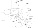
- FIG. 2 shows a side view of a deployed landing gear assembly according to a second embodiment
- FIG. 3 shows a perspective view of the LG assembly of the second embodiment, also when deployed
- FIG. 4 shows a side view of the LG assembly of the second embodiment during the process of moving the LG between its deployed and stowed positions
- FIG. 5 shows a perspective view of a fuselage of an aircraft according to a third embodiment
- FIG. 6 shows an aircraft illustrating the method according to a fourth embodiment of the invention.
- FIG. 1 shows an aircraft in accordance with a first embodiment of the invention.
- the aircraft 100 comprises two wings 102 and four retractable landing gear assemblies (three of which being shown in FIG. 1 ).
- There are two main landing gear assemblies 104 each being mounted on a respective wing of the aircraft.
- the two main landing gear assemblies each fold inboard to be stowed partially within the fuselage 106 .
- a nose landing gear is also provided (removed from view in FIG. 1 ).
- the two main landing gear assemblies 104 and the nose landing gear each carry two wheels 108 arranged coaxially on a single axle (in diablo formation) for rolling on the ground when the aircraft is on the ground.
- the aircraft 100 has a maximum take-off weight (MTOW) of about 120 tonnes, and an operating empty weight of about 65 tonnes.
- the weight of the aircraft is therefore just over the weight at which it would be appropriate for only six wheels to carry the entire weight of the aircraft.
- MTOW maximum take-off weight
- a non-wheeled central landing gear assembly 110 which in use shares the weight of the aircraft when on the ground, thus enabling the aircraft still to have only six wheels between the multiple wheeled landing gears.
- the non-wheeled central landing gear assembly 110 sustains compressive loads in the vertical direction, and negligible, shear, torsion, lateral or longitudinal loads. This is achieved by making the underside of the central landing gear assembly a low-friction surface.
- the low-friction surface is formed by a cushion of air formed by a source of compressed air and an air cushion device.
- the central landing gear can be slender in shape and have a relatively low mass structure.
- the structure to which the central landing gear is mounted may also be relatively lightweight and slender given that the loads to be reacted are effectively compressive loads aligned in substantially one and the same direction.
- an air cushion refers to the effect created by high pressure air reducing friction with the ground by means of an gap between the operating surface (i.e. ground) and the immediately adjacent structure of the landing gear assembly, while also reacting vertical loads therebetween.
- each main landing gear has a brake assembly 103 for applying a braking force to the MLG wheels.
- the resulting loads are transferred via the landing gear structure into the fuselage and wings.
- each MLG is configured to transmit non-vertical (braking) loads to the rest of the aircraft.
- the MLG is therefore relatively bulky and massive.
- the central landing gear (CLG) provides little (negligible) braking/drag loads as a result of friction between ground and CLG and thus does not need to be structured to transmit non-vertical (braking) loads to the rest of the aircraft.
- the MLG 104 each have two wheels 108 which can generate significant torsional loads in the landing gear when the aircraft is turning on the ground for example.
- Each wheel 108 is configured to facilitate movement of the aircraft along the ground in a longitudinal direction (i.e. when the wheel rotates about its axis) while resisting movement of the aircraft in a direction (labelled H in FIG. 1 ) along the ground perpendicular to the longitudinal direction (i.e. the wheel has a tyre that grips the surface on which the wheel rolls thus resisting movement of tyre along the ground in a direction parallel to the axle axis).
- the CLG facilitate movement along the ground in any direction (there being little or negligible difference in the coefficient of friction in one direction along the ground versus another direction).
- the CLG 110 is therefore relatively slender and lightweight.
- a second embodiment is shown in FIGS. 2 to 4 , and relates to an air cushion device 210 for use as a landing gear on an aircraft, for example an aircraft as shown in FIG. 1 .
- the reference numerals for the second embodiment are in the format 2XX, where last two digits (XX) are the same as between similar parts in the first and second embodiments.
- the aircraft 200 has two wheeled MLGs each carrying two wheels 208 .
- the device 210 is shown in FIGS. 2 and 3 mounted to an aircraft fuselage 206 , and in its deployed position.
- the device includes two independently powered air blowers 212 (one for back-up purposes) which each comprises a series of electrically powered air compressors, which draw air from an aft-facing inlet 214 .
- Compressed air is delivered as an annular ring of high pressure via an air plate 230 and associated skirt 232 .
- the device has a main load-bearing strut 216 mounted for rotation about a fixing 218 attached to the fuselage.
- the load-bearing strut includes a frangible portion 220 , which is designed to fail if the CLG is over-loaded in certain failure cases, so that the CLG fails in a controlled manner in preference to causing structural damage in the region of its mounting to the fuselage.
- the air cushion device 210 includes a pitch trimmer 222 that will be explained with reference to FIG. 4 .
- FIG. 4 shows the air cushion device 210 as it is being stowed—between the fully deployed position shown in FIG. 2 and the fully stowed position (not shown in the Figures).
- a hydraulic actuator 224 is provided for the purpose of moving the CLG between its deployed position and its stowed position. It will be seen that the geometry of the pitch trimmer 222 , its mounting 226 to the fuselage 206 and its mounting 228 to the lower part of the CLG, causes the air plate and skirt to be maintained relatively horizontal as they are raised/retracted. This enables the device to adopt a relatively shallow profile when stowed.
- Air passes from the air blower 212 over the plate 230 and out through a ring of air holes arranged at the periphery of the lowermost end 234 of the device 210 .
- the skirt 232 assists in maintaining air pressure in the region near the ground 236 . (It will be appreciated that the skirt does not contain the air cushion on all sides, in that a portion of the underside of the device is not closed by the skirt.)
- the arrangement of the skirt and the air-flow geometry may be in accordance with conventional air cushion generating means and/or of hovercraft-type vehicles of the prior art.
- the contact region (or region of closest proximity) between skirt and ground has a generally circular shape, with a diameter of about 2.5 m and an area of about 5 m 2 . (It will be appreciated that the skirt may not touch the ground very much, if at all, when the air cushion is functioning properly.)
- the ring 238 of material could be in the form of a flexible bladder around the circumference of the air cushion device, the bladder being inflated with a fluid so as to distribute the aircraft load on to the ground when the aircraft is in a power off condition.
- FIG. 5 shows schematically (in a dash-dot line 352 ) a section of the fuselage 306 of the aircraft in the region where a non-wheeled CLG (not shown in FIG. 5 ) is to be mounted.
- the reference numerals for the third embodiment are in the format 3XX, where last two digits (XX) refer to similar parts as described above.
- the Figure shows in solid line 350 a region (not representative of the structure of the fuselage) of the fuselage 306 which needs extra structural strengthening (and/or better distribution of loads) as a result of loading from the MLGs (not shown in FIG.
- An aircraft is typically provided with an I-beam, which acts as a keel beam, to provide the extra strength and load paths.
- I-beam acts as a keel beam, to provide the extra strength and load paths.
- a wheeled CLG and its associated structure would not fit in the space that could be provided if a central keel beam were also provided. Such a keel beam would need to be replaced with something else normally if a wheeled CLG were to be provided.
- Two parallel keel beams being disposed on opposite sides (port and starboard) of the longitudinal mid-plane of the aircraft would be one such alternative arrangement.
- the use of a non-wheeled CLG (not shown in FIG.
- a central keel beam for example according to either the first or second embodiment, with its slender and low-volume envelope when stowed, does not preclude the use of a central keel beam.
- a single centrally disposed I-beam (the general extent of which being shown schematically in FIG. 5 by means of a dashed line 354 ) is provided which extends in the longitudinal direction, l.
- the beam is thicker in width (w) but shorter in height (h). The CLG may thus be stowed in this region, and mounted to the beam, without there being a need to provide two parallel beams or the like.
- the four landing gear assemblies consist of a two-wheeled NLG (the location in plan of which being represented in FIG. 6 by the circular symbol 660 ), two two-wheeled MLGs (the location in plan of which being represented in FIG. 6 by the circular symbols 604 ) and a non-wheeled, low friction, CLG (the location in plan of which being represented in FIG. 6 by the circular symbol 610 ).
- the CLG 610 may be, but need not be, in the form of a CLG of any of the other illustrated embodiments.
- All landing gear assemblies of the aircraft are in contact with the runway, and at least 90% of the mass of the aircraft 600 is supported via the landing gear assemblies. Thus at least some—and possibly substantially all—of the weight of the aircraft is supported by and distributed between the four landing gear, as the aircraft moves along the operating surface. At a given instant, the aircraft is travelling at greater than 30 km/hour.
- the MLGs 604 and the CLG 610 each support at least 100 kN of the weight of the aircraft.
- the nose landing gear 660 supports less weight than the MLG 604 .
- each of the MLGs 604 experiences loads/torsion that are at least ten times higher than the equivalent loads experienced by the CLG 610 , as a result of the low-friction engagement of the CLG with the ground.
- the CLG can be made to be relatively lightweight.
- More than one non-wheeled LG could be provided.
- the source of compressed air for the air cushion could be provided from a source on the aircraft and not on or in the LG.
Landscapes
- Engineering & Computer Science (AREA)
- Aviation & Aerospace Engineering (AREA)
- Mechanical Engineering (AREA)
- Transportation (AREA)
- Tires In General (AREA)
Abstract
Description
Claims (19)
Applications Claiming Priority (3)
| Application Number | Priority Date | Filing Date | Title |
|---|---|---|---|
| GB1902748.1 | 2019-02-28 | ||
| GB1902748 | 2019-02-28 | ||
| GB1902748.1A GB2581833A (en) | 2019-02-28 | 2019-02-28 | Configuration of landing gear assemblies for an aircraft |
Publications (2)
| Publication Number | Publication Date |
|---|---|
| US20200298816A1 US20200298816A1 (en) | 2020-09-24 |
| US11292447B2 true US11292447B2 (en) | 2022-04-05 |
Family
ID=66377443
Family Applications (1)
| Application Number | Title | Priority Date | Filing Date |
|---|---|---|---|
| US16/798,895 Active 2040-06-10 US11292447B2 (en) | 2019-02-28 | 2020-02-24 | Configuration of landing gear assemblies for an aircraft |
Country Status (2)
| Country | Link |
|---|---|
| US (1) | US11292447B2 (en) |
| GB (1) | GB2581833A (en) |
Families Citing this family (5)
| Publication number | Priority date | Publication date | Assignee | Title |
|---|---|---|---|---|
| CN110758723B (en) * | 2019-12-06 | 2022-06-14 | 湖南浩天翼航空技术有限公司 | Unmanned aerial vehicle convenient to receive and release undercarriage |
| GB2602150A (en) * | 2020-12-21 | 2022-06-22 | Airbus Operations Ltd | An aircraft landing gear |
| US11630467B2 (en) * | 2020-12-23 | 2023-04-18 | Textron Innovations Inc. | VTOL aircraft having multifocal landing sensors |
| CN113109170B (en) * | 2021-04-20 | 2022-10-18 | 中国直升机设计研究所 | Composite material long beam strength test device |
| CN215098250U (en) * | 2021-05-27 | 2021-12-10 | 上海峰飞航空科技有限公司 | Vertical take-off and landing unmanned aerial vehicle |
Citations (11)
| Publication number | Priority date | Publication date | Assignee | Title |
|---|---|---|---|---|
| FR1266182A (en) | 1960-08-26 | 1961-07-07 | Sir George Godfrey & Partners | Braking device for vehicles |
| US3117747A (en) | 1960-11-18 | 1964-01-14 | English Electric Co Ltd | Vertical take-off aircraft |
| US3901988A (en) | 1973-12-03 | 1975-08-26 | Textron Inc | Inflatable trunk for air cushion supported vehicles |
| US3981462A (en) | 1974-07-31 | 1976-09-21 | Berezhnoi Igor A | Air-cushion landing gear for aircraft |
| EP0319051A2 (en) | 1987-12-04 | 1989-06-07 | The Boeing Company | Pivotally mounted high energy absorbing aircraft tail skid assembly having predetermined failure mode |
| WO1993011986A1 (en) | 1991-12-13 | 1993-06-24 | Viktor Nikolaevich Kizilov | Air-cushion flying vehicle |
| US20110204182A1 (en) | 2010-02-24 | 2011-08-25 | Eurocopter | Rotary wing aircraft provided with an emergency undercarriage |
| US20140151500A1 (en) * | 2012-11-30 | 2014-06-05 | Airbus Operations S.A.S. | Device for intermediate fastening between an aircraft fuselage and an aircraft landing gear |
| US20140374536A1 (en) * | 2013-01-16 | 2014-12-25 | William M. Otto | Aircraft wing |
| US20170174329A1 (en) * | 2015-12-22 | 2017-06-22 | Airbus Operations Limited | Aircraft landing gear |
| US9868521B2 (en) | 2016-01-14 | 2018-01-16 | Embraer S.A. | Retractable self-aligning aircraft stablizer strut assembly and aircraft including the same |
Family Cites Families (1)
| Publication number | Priority date | Publication date | Assignee | Title |
|---|---|---|---|---|
| FR2676182B1 (en) * | 1991-05-06 | 1994-04-15 | Gaz De France | NON-SELECTIVE OXIDATION CATALYST AND PREPARATION METHOD THEREOF. |
-
2019
- 2019-02-28 GB GB1902748.1A patent/GB2581833A/en not_active Withdrawn
-
2020
- 2020-02-24 US US16/798,895 patent/US11292447B2/en active Active
Patent Citations (11)
| Publication number | Priority date | Publication date | Assignee | Title |
|---|---|---|---|---|
| FR1266182A (en) | 1960-08-26 | 1961-07-07 | Sir George Godfrey & Partners | Braking device for vehicles |
| US3117747A (en) | 1960-11-18 | 1964-01-14 | English Electric Co Ltd | Vertical take-off aircraft |
| US3901988A (en) | 1973-12-03 | 1975-08-26 | Textron Inc | Inflatable trunk for air cushion supported vehicles |
| US3981462A (en) | 1974-07-31 | 1976-09-21 | Berezhnoi Igor A | Air-cushion landing gear for aircraft |
| EP0319051A2 (en) | 1987-12-04 | 1989-06-07 | The Boeing Company | Pivotally mounted high energy absorbing aircraft tail skid assembly having predetermined failure mode |
| WO1993011986A1 (en) | 1991-12-13 | 1993-06-24 | Viktor Nikolaevich Kizilov | Air-cushion flying vehicle |
| US20110204182A1 (en) | 2010-02-24 | 2011-08-25 | Eurocopter | Rotary wing aircraft provided with an emergency undercarriage |
| US20140151500A1 (en) * | 2012-11-30 | 2014-06-05 | Airbus Operations S.A.S. | Device for intermediate fastening between an aircraft fuselage and an aircraft landing gear |
| US20140374536A1 (en) * | 2013-01-16 | 2014-12-25 | William M. Otto | Aircraft wing |
| US20170174329A1 (en) * | 2015-12-22 | 2017-06-22 | Airbus Operations Limited | Aircraft landing gear |
| US9868521B2 (en) | 2016-01-14 | 2018-01-16 | Embraer S.A. | Retractable self-aligning aircraft stablizer strut assembly and aircraft including the same |
Non-Patent Citations (2)
| Title |
|---|
| [Online], "The Fifth Column Forum, Air warfare, The Week in Technology", Nov. 27- Dec. 1, 2017, XMB, printed Feb. 16, 2020, 3 pages. |
| Combined Search and Examination Report for GB1902748.1 dated Jul. 31, 2019, 8 pages. |
Also Published As
| Publication number | Publication date |
|---|---|
| GB2581833A (en) | 2020-09-02 |
| US20200298816A1 (en) | 2020-09-24 |
| GB201902748D0 (en) | 2019-04-17 |
Similar Documents
| Publication | Publication Date | Title |
|---|---|---|
| US11292447B2 (en) | Configuration of landing gear assemblies for an aircraft | |
| RU2264315C2 (en) | Hybrid flying vehicle | |
| US11059571B2 (en) | Aircraft landing gear assembly | |
| CN104417747B (en) | The method of aircraft and transformation aircraft with many deck fuselages of afterbody splitlevel | |
| US4638962A (en) | Jumbo aircraft, in particular of high-wing monoplane design | |
| US20070057118A1 (en) | Rotary wing aircraft and a carrier structure | |
| US11919625B2 (en) | Aircraft landing gear assembly | |
| US12122506B2 (en) | Aircraft having outrigger landing gear | |
| CN109436283B (en) | Wing type variant airship | |
| RU2398710C2 (en) | Method and device facilitating aircraft landing gear front leg breaking ground | |
| EP3242832A1 (en) | Aircraft landing gear, aircraft carrying such and methods | |
| CN210027054U (en) | High-speed train for vacuum pipeline magnetic levitation transportation system and magnetic levitation transportation system | |
| CN101304919B (en) | Aircraft and method for braked pivot turning of an aircraft on the ground | |
| US2685420A (en) | Airplane with lifting fuselage, landing flaps, and quadricycle landing gear | |
| CN107512388A (en) | A kind of the aircraft takeoffs and landings control system and method for the separation of Flight main body and undercarriage | |
| US11021245B2 (en) | VTOL aircraft | |
| CN111845368B (en) | High-speed train for vacuum pipeline magnetic levitation transportation system and magnetic levitation transportation system | |
| US20190023380A1 (en) | Rotorcraft having at least one undercarriage with at least one inclined wheel, and a method | |
| EP4144638B1 (en) | Aircraft landing gear assembly | |
| EP3392138A1 (en) | Aircraft landing gear assembly | |
| Besch | Large aircraft landing gears–a brief overview | |
| US4852829A (en) | Undercarriage apparatus for vertical-lift aircraft | |
| Liseitsev | Landing Gear Design | |
| Design | Graduates' and Students' Section | |
| Atabay | Dynamics of a landing gear mechanism |
Legal Events
| Date | Code | Title | Description |
|---|---|---|---|
| FEPP | Fee payment procedure |
Free format text: ENTITY STATUS SET TO UNDISCOUNTED (ORIGINAL EVENT CODE: BIG.); ENTITY STATUS OF PATENT OWNER: LARGE ENTITY |
|
| STPP | Information on status: patent application and granting procedure in general |
Free format text: DOCKETED NEW CASE - READY FOR EXAMINATION |
|
| STPP | Information on status: patent application and granting procedure in general |
Free format text: NON FINAL ACTION MAILED |
|
| STPP | Information on status: patent application and granting procedure in general |
Free format text: RESPONSE TO NON-FINAL OFFICE ACTION ENTERED AND FORWARDED TO EXAMINER |
|
| STPP | Information on status: patent application and granting procedure in general |
Free format text: NOTICE OF ALLOWANCE MAILED -- APPLICATION RECEIVED IN OFFICE OF PUBLICATIONS |
|
| AS | Assignment |
Owner name: AIRBUS OPERATIONS LIMITED, UNITED KINGDOM Free format text: ASSIGNMENT OF ASSIGNORS INTEREST;ASSIGNOR:WILSON, FRASER;REEL/FRAME:058339/0504 Effective date: 20211027 |
|
| STPP | Information on status: patent application and granting procedure in general |
Free format text: PUBLICATIONS -- ISSUE FEE PAYMENT VERIFIED |
|
| STCF | Information on status: patent grant |
Free format text: PATENTED CASE |
|
| MAFP | Maintenance fee payment |
Free format text: PAYMENT OF MAINTENANCE FEE, 4TH YEAR, LARGE ENTITY (ORIGINAL EVENT CODE: M1551); ENTITY STATUS OF PATENT OWNER: LARGE ENTITY Year of fee payment: 4 |