US11291611B2 - Multi-lumen gastrointestinal feeding and aspirating catheter assemblies - Google Patents
Multi-lumen gastrointestinal feeding and aspirating catheter assemblies Download PDFInfo
- Publication number
- US11291611B2 US11291611B2 US16/003,974 US201816003974A US11291611B2 US 11291611 B2 US11291611 B2 US 11291611B2 US 201816003974 A US201816003974 A US 201816003974A US 11291611 B2 US11291611 B2 US 11291611B2
- Authority
- US
- United States
- Prior art keywords
- lumen
- catheter
- aspirating
- catheter assembly
- venting
- Prior art date
- Legal status (The legal status is an assumption and is not a legal conclusion. Google has not performed a legal analysis and makes no representation as to the accuracy of the status listed.)
- Active, expires
Links
Images


Classifications
-
- A—HUMAN NECESSITIES
- A61—MEDICAL OR VETERINARY SCIENCE; HYGIENE
- A61J—CONTAINERS SPECIALLY ADAPTED FOR MEDICAL OR PHARMACEUTICAL PURPOSES; DEVICES OR METHODS SPECIALLY ADAPTED FOR BRINGING PHARMACEUTICAL PRODUCTS INTO PARTICULAR PHYSICAL OR ADMINISTERING FORMS; DEVICES FOR ADMINISTERING FOOD OR MEDICINES ORALLY; BABY COMFORTERS; DEVICES FOR RECEIVING SPITTLE
- A61J15/00—Feeding-tubes for therapeutic purposes
- A61J15/0026—Parts, details or accessories for feeding-tubes
- A61J15/0096—Provisions for venting
-
- A—HUMAN NECESSITIES
- A61—MEDICAL OR VETERINARY SCIENCE; HYGIENE
- A61J—CONTAINERS SPECIALLY ADAPTED FOR MEDICAL OR PHARMACEUTICAL PURPOSES; DEVICES OR METHODS SPECIALLY ADAPTED FOR BRINGING PHARMACEUTICAL PRODUCTS INTO PARTICULAR PHYSICAL OR ADMINISTERING FORMS; DEVICES FOR ADMINISTERING FOOD OR MEDICINES ORALLY; BABY COMFORTERS; DEVICES FOR RECEIVING SPITTLE
- A61J15/00—Feeding-tubes for therapeutic purposes
- A61J15/0003—Nasal or oral feeding-tubes, e.g. tube entering body through nose or mouth
- A61J15/0007—Nasal or oral feeding-tubes, e.g. tube entering body through nose or mouth inserted by using a guide-wire
-
- A—HUMAN NECESSITIES
- A61—MEDICAL OR VETERINARY SCIENCE; HYGIENE
- A61J—CONTAINERS SPECIALLY ADAPTED FOR MEDICAL OR PHARMACEUTICAL PURPOSES; DEVICES OR METHODS SPECIALLY ADAPTED FOR BRINGING PHARMACEUTICAL PRODUCTS INTO PARTICULAR PHYSICAL OR ADMINISTERING FORMS; DEVICES FOR ADMINISTERING FOOD OR MEDICINES ORALLY; BABY COMFORTERS; DEVICES FOR RECEIVING SPITTLE
- A61J15/00—Feeding-tubes for therapeutic purposes
- A61J15/0026—Parts, details or accessories for feeding-tubes
- A61J15/0073—Multi-lumen tubes
-
- A—HUMAN NECESSITIES
- A61—MEDICAL OR VETERINARY SCIENCE; HYGIENE
- A61J—CONTAINERS SPECIALLY ADAPTED FOR MEDICAL OR PHARMACEUTICAL PURPOSES; DEVICES OR METHODS SPECIALLY ADAPTED FOR BRINGING PHARMACEUTICAL PRODUCTS INTO PARTICULAR PHYSICAL OR ADMINISTERING FORMS; DEVICES FOR ADMINISTERING FOOD OR MEDICINES ORALLY; BABY COMFORTERS; DEVICES FOR RECEIVING SPITTLE
- A61J15/00—Feeding-tubes for therapeutic purposes
- A61J15/0026—Parts, details or accessories for feeding-tubes
- A61J15/0092—Valves on feeding tubes
-
- A61M1/0058—
-
- A—HUMAN NECESSITIES
- A61—MEDICAL OR VETERINARY SCIENCE; HYGIENE
- A61M—DEVICES FOR INTRODUCING MEDIA INTO, OR ONTO, THE BODY; DEVICES FOR TRANSDUCING BODY MEDIA OR FOR TAKING MEDIA FROM THE BODY; DEVICES FOR PRODUCING OR ENDING SLEEP OR STUPOR
- A61M1/00—Suction or pumping devices for medical purposes; Devices for carrying-off, for treatment of, or for carrying-over, body-liquids; Drainage systems
- A61M1/71—Suction drainage systems
- A61M1/77—Suction-irrigation systems
-
- A—HUMAN NECESSITIES
- A61—MEDICAL OR VETERINARY SCIENCE; HYGIENE
- A61M—DEVICES FOR INTRODUCING MEDIA INTO, OR ONTO, THE BODY; DEVICES FOR TRANSDUCING BODY MEDIA OR FOR TAKING MEDIA FROM THE BODY; DEVICES FOR PRODUCING OR ENDING SLEEP OR STUPOR
- A61M1/00—Suction or pumping devices for medical purposes; Devices for carrying-off, for treatment of, or for carrying-over, body-liquids; Drainage systems
- A61M1/84—Drainage tubes; Aspiration tips
- A61M1/85—Drainage tubes; Aspiration tips with gas or fluid supply means, e.g. for supplying rinsing fluids or anticoagulants
-
- A—HUMAN NECESSITIES
- A61—MEDICAL OR VETERINARY SCIENCE; HYGIENE
- A61M—DEVICES FOR INTRODUCING MEDIA INTO, OR ONTO, THE BODY; DEVICES FOR TRANSDUCING BODY MEDIA OR FOR TAKING MEDIA FROM THE BODY; DEVICES FOR PRODUCING OR ENDING SLEEP OR STUPOR
- A61M25/00—Catheters; Hollow probes
- A61M25/0021—Catheters; Hollow probes characterised by the form of the tubing
- A61M25/0023—Catheters; Hollow probes characterised by the form of the tubing by the form of the lumen, e.g. cross-section, variable diameter
- A61M25/0026—Multi-lumen catheters with stationary elements
- A61M25/0032—Multi-lumen catheters with stationary elements characterized by at least one unconventionally shaped lumen, e.g. polygons, ellipsoids, wedges or shapes comprising concave and convex parts
-
- A—HUMAN NECESSITIES
- A61—MEDICAL OR VETERINARY SCIENCE; HYGIENE
- A61M—DEVICES FOR INTRODUCING MEDIA INTO, OR ONTO, THE BODY; DEVICES FOR TRANSDUCING BODY MEDIA OR FOR TAKING MEDIA FROM THE BODY; DEVICES FOR PRODUCING OR ENDING SLEEP OR STUPOR
- A61M25/00—Catheters; Hollow probes
- A61M25/0067—Catheters; Hollow probes characterised by the distal end, e.g. tips
- A61M25/0068—Static characteristics of the catheter tip, e.g. shape, atraumatic tip, curved tip or tip structure
- A61M25/007—Side holes, e.g. their profiles or arrangements; Provisions to keep side holes unblocked
-
- A—HUMAN NECESSITIES
- A61—MEDICAL OR VETERINARY SCIENCE; HYGIENE
- A61J—CONTAINERS SPECIALLY ADAPTED FOR MEDICAL OR PHARMACEUTICAL PURPOSES; DEVICES OR METHODS SPECIALLY ADAPTED FOR BRINGING PHARMACEUTICAL PRODUCTS INTO PARTICULAR PHYSICAL OR ADMINISTERING FORMS; DEVICES FOR ADMINISTERING FOOD OR MEDICINES ORALLY; BABY COMFORTERS; DEVICES FOR RECEIVING SPITTLE
- A61J15/00—Feeding-tubes for therapeutic purposes
- A61J15/0026—Parts, details or accessories for feeding-tubes
- A61J15/0076—Feeding pumps
-
- A—HUMAN NECESSITIES
- A61—MEDICAL OR VETERINARY SCIENCE; HYGIENE
- A61M—DEVICES FOR INTRODUCING MEDIA INTO, OR ONTO, THE BODY; DEVICES FOR TRANSDUCING BODY MEDIA OR FOR TAKING MEDIA FROM THE BODY; DEVICES FOR PRODUCING OR ENDING SLEEP OR STUPOR
- A61M25/00—Catheters; Hollow probes
- A61M25/0021—Catheters; Hollow probes characterised by the form of the tubing
- A61M25/0023—Catheters; Hollow probes characterised by the form of the tubing by the form of the lumen, e.g. cross-section, variable diameter
- A61M2025/0025—Catheters; Hollow probes characterised by the form of the tubing by the form of the lumen, e.g. cross-section, variable diameter having a collapsible lumen
-
- A—HUMAN NECESSITIES
- A61—MEDICAL OR VETERINARY SCIENCE; HYGIENE
- A61M—DEVICES FOR INTRODUCING MEDIA INTO, OR ONTO, THE BODY; DEVICES FOR TRANSDUCING BODY MEDIA OR FOR TAKING MEDIA FROM THE BODY; DEVICES FOR PRODUCING OR ENDING SLEEP OR STUPOR
- A61M25/00—Catheters; Hollow probes
- A61M25/0021—Catheters; Hollow probes characterised by the form of the tubing
- A61M25/0023—Catheters; Hollow probes characterised by the form of the tubing by the form of the lumen, e.g. cross-section, variable diameter
- A61M25/0026—Multi-lumen catheters with stationary elements
- A61M25/003—Multi-lumen catheters with stationary elements characterized by features relating to least one lumen located at the distal part of the catheter, e.g. filters, plugs or valves
- A61M2025/0031—Multi-lumen catheters with stationary elements characterized by features relating to least one lumen located at the distal part of the catheter, e.g. filters, plugs or valves characterized by lumina for withdrawing or delivering, i.e. used for extracorporeal circuit treatment
-
- A—HUMAN NECESSITIES
- A61—MEDICAL OR VETERINARY SCIENCE; HYGIENE
- A61M—DEVICES FOR INTRODUCING MEDIA INTO, OR ONTO, THE BODY; DEVICES FOR TRANSDUCING BODY MEDIA OR FOR TAKING MEDIA FROM THE BODY; DEVICES FOR PRODUCING OR ENDING SLEEP OR STUPOR
- A61M25/00—Catheters; Hollow probes
- A61M25/0021—Catheters; Hollow probes characterised by the form of the tubing
- A61M25/0023—Catheters; Hollow probes characterised by the form of the tubing by the form of the lumen, e.g. cross-section, variable diameter
- A61M25/0026—Multi-lumen catheters with stationary elements
- A61M2025/0037—Multi-lumen catheters with stationary elements characterized by lumina being arranged side-by-side
-
- A—HUMAN NECESSITIES
- A61—MEDICAL OR VETERINARY SCIENCE; HYGIENE
- A61M—DEVICES FOR INTRODUCING MEDIA INTO, OR ONTO, THE BODY; DEVICES FOR TRANSDUCING BODY MEDIA OR FOR TAKING MEDIA FROM THE BODY; DEVICES FOR PRODUCING OR ENDING SLEEP OR STUPOR
- A61M2210/00—Anatomical parts of the body
- A61M2210/06—Head
- A61M2210/0618—Nose
-
- A—HUMAN NECESSITIES
- A61—MEDICAL OR VETERINARY SCIENCE; HYGIENE
- A61M—DEVICES FOR INTRODUCING MEDIA INTO, OR ONTO, THE BODY; DEVICES FOR TRANSDUCING BODY MEDIA OR FOR TAKING MEDIA FROM THE BODY; DEVICES FOR PRODUCING OR ENDING SLEEP OR STUPOR
- A61M2210/00—Anatomical parts of the body
- A61M2210/06—Head
- A61M2210/0625—Mouth
-
- A—HUMAN NECESSITIES
- A61—MEDICAL OR VETERINARY SCIENCE; HYGIENE
- A61M—DEVICES FOR INTRODUCING MEDIA INTO, OR ONTO, THE BODY; DEVICES FOR TRANSDUCING BODY MEDIA OR FOR TAKING MEDIA FROM THE BODY; DEVICES FOR PRODUCING OR ENDING SLEEP OR STUPOR
- A61M2210/00—Anatomical parts of the body
- A61M2210/10—Trunk
- A61M2210/1042—Alimentary tract
- A61M2210/1053—Stomach
-
- A—HUMAN NECESSITIES
- A61—MEDICAL OR VETERINARY SCIENCE; HYGIENE
- A61M—DEVICES FOR INTRODUCING MEDIA INTO, OR ONTO, THE BODY; DEVICES FOR TRANSDUCING BODY MEDIA OR FOR TAKING MEDIA FROM THE BODY; DEVICES FOR PRODUCING OR ENDING SLEEP OR STUPOR
- A61M2210/00—Anatomical parts of the body
- A61M2210/10—Trunk
- A61M2210/1042—Alimentary tract
- A61M2210/106—Small intestine
-
- A—HUMAN NECESSITIES
- A61—MEDICAL OR VETERINARY SCIENCE; HYGIENE
- A61M—DEVICES FOR INTRODUCING MEDIA INTO, OR ONTO, THE BODY; DEVICES FOR TRANSDUCING BODY MEDIA OR FOR TAKING MEDIA FROM THE BODY; DEVICES FOR PRODUCING OR ENDING SLEEP OR STUPOR
- A61M2210/00—Anatomical parts of the body
- A61M2210/10—Trunk
- A61M2210/1042—Alimentary tract
- A61M2210/1064—Large intestine
-
- A—HUMAN NECESSITIES
- A61—MEDICAL OR VETERINARY SCIENCE; HYGIENE
- A61M—DEVICES FOR INTRODUCING MEDIA INTO, OR ONTO, THE BODY; DEVICES FOR TRANSDUCING BODY MEDIA OR FOR TAKING MEDIA FROM THE BODY; DEVICES FOR PRODUCING OR ENDING SLEEP OR STUPOR
- A61M2240/00—Specially adapted for neonatal use
Definitions
- the present disclosure relates generally to catheter assemblies. More specifically, the present disclosure relates to multi-lumen catheter assemblies and related methods of use.
- FIG. 1 is a perspective view of a multi-lumen catheter assembly being used with a patient, according to one embodiment of the present disclosure.
- FIG. 2 is a perspective view of a multi-lumen catheter assembly, according to another embodiment of the present disclosure.
- FIG. 3 is an enlarged cross-sectional view of a portion of a multi-lumen catheter assembly, such as the multi-lumen catheter assembly of FIG. 2 .
- FIGS. 4A and 4B are additional enlarged cross-sectional views of a portion of a multi-lumen catheter assembly, such as the multi-lumen catheter assembly of FIG. 2 .
- FIGS. 5A and 5B are additional enlarged cross-sectional views of a portion of a multi-lumen catheter assembly, such as the multi-lumen catheter assembly of FIG. 2 .
- FIG. 6 is a perspective view of a multi-lumen catheter assembly, according to another embodiment of the present disclosure.
- FIG. 7 is a perspective view of a portion of a multi-lumen catheter assembly, according to another embodiment of the present disclosure.
- FIG. 8 is a perspective view of a multi-lumen catheter assembly, according to another embodiment of the present disclosure.
- FIG. 9 is a perspective view of a multi-lumen catheter assembly, according to another embodiment of the present disclosure.
- FIG. 10 is a flowchart of a method of using a multi-lumen catheter assembly, according to another embodiment of the present disclosure.
- the various embodiments disclosed herein generally relate to catheter assemblies. More specifically, the present disclosure relates to multi-lumen catheter assemblies and related methods of use.
- the catheter assembly comprises a multi-lumen catheter, a junction hub, and extension legs.
- the multi-lumen catheter assembly can be employed or otherwise used as a gastrointestinal feeding and aspirating device. For example, one lumen of the multi-lumen catheter assembly can be used as a feeding channel, and another lumen can be used as an aspiration channel. Other uses are also contemplated.
- the catheter assembly comprises a preformed multi-lumen catheter comprising a first lumen, a second lumen, and a first distal opening.
- the first distal opening can extend through a side wall of the catheter and can be in fluid communication with the second lumen.
- a sheath comprising a membrane that is permeable to one or more gases and impermeable to one or more liquids or solids can be disposed around at least a portion of the catheter such that it covers the first distal opening.
- the preformed catheter distal end (and/or an intermediate section) can also assume a non-linear three-dimensional configuration when the catheter is in a relaxed state (e.g., a state prior to and/or after deployment), and a substantially linear configuration in a deployment state (e.g., an introduction or insertion state).
- a relaxed state e.g., a state prior to and/or after deployment
- a substantially linear configuration in a deployment state e.g., an introduction or insertion state
- the catheter assembly can also be configured to couple to a vacuum source, wherein the vacuum source can be configured to reduce pressure in at least a portion of the second lumen, causing one or more gases to be drawn from the body of a patient through the distal opening and into the second lumen and/or out of the catheter assembly.
- the catheter assembly can also be configured such that the sheath does not prohibit flow of the one or more gases through the second lumen when the portion of the second lumen is under reduced pressure.
- a method of using a catheter assembly can comprise a step of inserting a distal end of a multi-lumen catheter through a nasal or oral passage and into a stomach or bowel of a patient.
- the method can further comprise steps of coupling a feed system to the multi-lumen catheter such that the feed system is in fluid communication with a first lumen, and delivering food from the feed system through the first lumen and into the patient.
- the method can also comprise simultaneously venting or aspirating one or more gases through a second lumen.
- the phrases “connected to,” “coupled to,” and “in communication with” refer to any form of interaction between two or more entities, including but not limited to mechanical, electrical, magnetic, electromagnetic, fluid, and thermal interaction.
- Two components may be coupled to each other even though they are not in direct contact with each other.
- two components may be coupled to each other through an intermediate component.
- proximal and distal refer to opposite ends of a medical device, including the devices disclosed herein.
- the proximal portion of a medical device is the portion nearest a practitioner during use, while the distal portion is a portion at the opposite end.
- the proximal end of a catheter assembly is defined as the end closest to the practitioner during insertion or utilization of the catheter assembly.
- the distal end is the end opposite the proximal end, along the longitudinal direction of the catheter assembly.
- FIG. 1 depicts a multi-lumen catheter assembly 100 being used with a patient 10 , according to one embodiment of the present disclosure.
- the catheter assembly 100 comprises a multi-lumen catheter 110 , which can also be described as a catheter 110 , a catheter body 110 , or an elongate member 110 .
- the catheter assembly 100 also comprises a junction hub 130 and two or more extension legs 140 , 150 (which can also be described as extension tubes 140 , 150 ).
- the catheter assembly 100 further comprises one or more connectors 142 , 152 (which can also be described as couplers 142 , 152 or coupling members 142 , 152 , etc.).
- the catheter assembly 100 is configured to provide a passageway for components and/or substances into and/or out of a body of a patient 10 .
- the catheter assembly 100 can be employed as a gastrointestinal feeding and aspirating device.
- the multi-lumen catheter 110 can be passed or otherwise disposed through the nasal passage (or oral passage) and into the stomach 12 (or an intestine or bowel) of the patient 10 .
- one lumen (e.g., a first lumen) of the multi-lumen catheter 110 can be configured to deliver a food source (e.g., a liquid food source) to a patient 10
- another lumen (e.g., a second lumen) of the catheter 110 can be configured to vent and/or aspirate one or more gases from the patient 10 .
- the multi-lumen catheter assembly 100 is configured for use with an infant. However, it will be appreciated that the catheter assembly 100 can be used with patients of all ages, as desired.
- the multi-lumen catheter 110 can comprise two or more lumens, or channels, extending therethrough.
- the multi-lumen catheter 110 comprises two lumens and can be referred to as a dual lumen catheter.
- the multi-lumen catheter 110 comprises three or more lumens (e.g., one feeding lumen and two venting and/or aspiration lumens).
- the catheter 110 also comprises a distal end 112 , an intermediate section 108 , and a proximal end 114 .
- the distal end 112 is configured to be disposed in the body (or a body cavity) of the patient 10 during use.
- the distal end 112 is disposed in the stomach 12 of the patient 10 .
- the distal end 112 can be disposed in an intestine (e.g., small intestine) or bowel of the patient 10 (as shown in FIG. 8 .)
- the proximal end 114 of the catheter 110 is configured to be disposed outside of the body of the patient 10 during use.
- the proximal end 114 can also be coupled to extension legs 140 , 150 by a junction hub 130 , as shown in FIG. 1 .
- the proximal end 114 can be coupled to a junction hub 130 , which is also coupled to extension legs 140 , 150 .
- the extension legs 140 , 150 can be used to longitudinally extend one or more proximal openings or ports 144 , 154 from the junction hub 130 and/or the catheter 110 .
- Each extension leg 140 , 150 comprises a lumen extending longitudinally therethrough, which provides a passageway for components and/or substances between the proximal openings 144 , 154 and the junction hub 130 .
- the junction hub 130 can then be used to couple the lumen of the first extension leg 140 to a first lumen of the catheter 110 , and to couple the lumen of the second extension leg 150 to a second lumen of the catheter 110 .
- the proximal openings 144 , 154 are disposed at the proximal end 102 of the catheter assembly 100 .
- the proximal openings 144 , 154 are configured for use in introducing and/or withdrawing various components and/or substances from the catheter assembly 100 .
- a first proximal opening 144 can be used for introducing a food source (e.g., a liquid food source) to the patient 10
- a second proximal opening 154 can be used to withdraw or vent one or more gases.
- the first opening 144 can be described as a food opening or food port
- the second opening 154 can be described as a gas opening or gas port.
- one or more of the proximal opening 144 , 154 may also extend through additional hubs, fittings, and/or connectors 142 , 152 , which may also be coupled to the extension legs 140 , 150 and disposed at the proximal end 102 of the catheter assembly 100 .
- one or more of the proximal openings 144 , 154 may extend through a luer connector or an enteral feeding connector.
- Other types of hubs, fittings, and/or connectors 142 , 152 can also be used as desired. Further, in some embodiments different types of connectors 142 , 152 are used.
- a first type of connector 142 (e.g., such as an enteral feeding connector) is coupled to the first extension leg 140
- a second type of connector 152 is coupled to the second extension leg 150 .
- Use of different types of connectors 142 , 152 can aid in identifying the different lumens of the catheter 110 .
- a first connector 142 may be associated with a lumen of the catheter 110 that is configured to deliver a food source to the patient 10
- a second connector 152 may be associated with a lumen of the catheter 110 that is configured to withdraw or vent one or more gases.
- a food source or feed system 20 can be coupled to and/or otherwise used with the catheter assembly 100 .
- a feed system 20 is coupled to a first extension leg 140 through a first connector 142 (e.g., such as an enteral feeding connector).
- first connector 142 e.g., such as an enteral feeding connector
- feed systems 20 can be used, including but not limited to feed reservoirs, feed pumps, syringes, or other types of feed systems that are known and/or used in delivering a food source to a patient 10 .
- food from the feed system 20 can be delivered through the first proximal opening 144 , through the first extension leg 140 , through the junction hub 130 , through the first lumen of the catheter 110 , and into the body (e.g., stomach 12 ) of the patient 10 .
- the first lumen of the catheter 110 can be described as being coupled to, or in fluid communication with, the first proximal opening 144 and/or the feed system 20 .
- a vacuum source 30 is optionally coupled to and/or otherwise used with the catheter assembly 100 .
- a vacuum source 30 is optionally coupled to a second extension leg 150 through a second connector 152 .
- Various types of vacuum sources 30 can be used, including but not limited to vacuum pumps, syringes, or other types of vacuum sources that are known and/or used in withdrawing gases, creating a vacuum or suction, or otherwise reducing pressure.
- a vacuum can describe as a space having a pressure that is lower than atmospheric pressure.
- the vacuum source 30 can be configured to reduce pressure in one or more regions within the catheter assembly 100 , causing one or more gases to be drawn from the body (e.g., stomach 12 ) of the patient 10 and into a catheter lumen and/or out of the catheter assembly 100 .
- the vacuum source 30 can be configured to aspirate one or more gases from the body (e.g., stomach 12 ) of the patient 10 .
- the vacuum source 30 can be configured to deliver an intermittent vacuum to the catheter assembly 100 .
- the vacuum source 30 may be configured to turn on and/or off intermittently.
- the vacuum source 30 can be configured to deliver a constant or continuous vacuum to the catheter assembly 100 .
- no vacuum source 30 is required, and the opening 154 can be left open for aspiration or venting at ambient conditions.
- the gas can vent or aspirate out of the body of the patient 10 naturally, without the application of a vacuum from a vacuum source 30 .
- gas from the patient 10 can be vented or aspirated by traveling from the body of the patient 10 , through the second lumen of the catheter 110 , through the junction hub 130 , through the second extension leg 150 , and out of the second opening 154 .
- the second lumen of the catheter 110 can be described as being in fluid communication with the second opening 154 , and/or optionally a vacuum source 30 .
- the catheter assembly 100 can be configured for simultaneous feeding and aspiration.
- at least two lumens of the catheter 110 can be separate and distinct from one another (e.g., separated by one or more inner walls).
- food can be delivered through a first lumen of the catheter 110 at the same time as one or more gases are being vented or aspirated through the second lumen.
- the catheter assembly 100 can also be left disposed within the patient 10 for a prolonged period of time with little or no adverse effects.
- the catheter assembly 100 can be disposed within the patient 10 after which a first feeding session can be initiated (during which venting or aspiration can simultaneously occur with or without the use of a vacuum source 30 ).
- the feed system 20 can be turned off and/or uncoupled from the first extension leg 140 .
- Any optional vacuum source 30 being used can also be either uncoupled from the second extension leg 150 , or left coupled for intermittent or continued venting or aspiration.
- a second feeding session can thereafter be initiated at any desired time.
- an alternative feeding session can also be initiated while the catheter assembly 100 is left in place.
- the patient 10 can be fed orally (e.g., through the mouth) while the catheter assembly 100 is disposed through the nasal passage.
- an infant can be bottle or breast fed orally without removal of the catheter assembly 100 .
- FIG. 2 illustrates a catheter assembly 200 in accordance with another embodiment of the present disclosure.
- the catheter assembly 200 can, in certain respects, resemble the catheter assembly 100 described above in FIG. 1 . Accordingly, like features are designated with like reference numerals, with the leading digits incremented to “2.” Relevant disclosure set forth above regarding similarly identified features thus may not be repeated hereafter. Moreover, specific features of the catheter assembly 200 may not be shown or identified by a reference numeral in the drawings or specifically discussed in the written description that follows. However, such features may clearly be the same, or substantially the same, as features depicted in other embodiments and/or described with respect to such embodiments. Accordingly, the relevant descriptions of such features apply equally to the features of the catheter assembly 200 .
- the catheter assembly 200 comprises a catheter 210 having a distal end 212 , an intermediate section 208 , and a proximal end 214 .
- the catheter assembly 200 also comprises a junction hub 230 , first and second extension legs 240 , 250 , and first and second connectors 242 , 252 .
- the catheter assembly 200 also comprises a sheath 220 disposed on and/or around at least a portion of the catheter 210 .
- the sheath 220 can be disposed around at least a portion of the intermediate section 208 of the catheter 210 .
- the sheath 220 can be configured to selectively allow passage of one or more substances into and/or out of the catheter 210 .
- the sheath 220 comprises a permeable or semi-permeable membrane.
- the membrane can allow passage of one or more gases, while restricting (or otherwise minimizing) the passage of other molecules such as liquids and solids (e.g., liquid and/or solid foods, aqueous liquids, or other bodily fluids, etc.).
- the membrane can be described as being permeable to one or more gases, and impermeable (or substantially impermeable) to other substances (e.g., such as liquids and solids).
- a polymeric membrane comprising a fluoropolymer is used.
- a polymeric membrane comprising polytetrafluoroethylene (PTFE) is used.
- the polytetrafluoroethylene can also be expanded (e.g., ePTFE).
- Other types of polymeric membranes can also be used.
- the sheath 220 or membrane can also have various degrees of selectivity.
- the degree of selectivity (or the selectivity) of the membrane can be dependent upon the membrane pore size.
- membranes having a larger pore size can be configured to allow passage of larger molecules, while membranes having a smaller pore size can be configured to allow passage of smaller molecules.
- the membrane comprises pore sizes of less than about 100 microns, less than about 50 microns, less than about 25 microns, less than about 10 microns, or less than about 5 microns.
- the membrane comprises pore sizes of between about 0.001 microns and about 100 microns, or between about 0.01 microns and about 50 microns.
- the membrane comprises pore sizes of between about 0.01 microns and about 10 microns, between about 0.05 microns and about 5 microns, between about 0.1 microns and about 3 microns, or between about 0.2 microns and about 1 micron. Membranes having other pore sizes (e.g., larger or smaller) can also be used.
- the sheath 220 is configured to cover one or more distal openings 224 in the catheter 210 .
- the catheter 210 can comprise one or more distal openings 224 disposed on a side wall of the catheter 210 .
- the one or more distal openings 224 are disposed along a longitudinal length of the catheter 210 .
- the one or more distal openings 224 are aligned along a longitudinal length of the catheter 210 .
- the one or more distal openings 224 can extend through the side wall and can be in fluid communication with a lumen of the catheter 210 (such as a second lumen that is configured to vent or aspirate one or more gases).
- the sheath 220 can be configured to selectively allow passage of one or more substances (e.g., gases) through the one or more distal openings 224 and into the lumen of the catheter 210 , while restricting the passage of other substances (e.g., liquids or solids).
- the catheter assembly 200 further comprises a clamp 232 and/or valve.
- a pinch clamp 232 is used on one or more of the extension legs 240 , 250 of the catheter assembly 200 .
- a pinch clamp 232 is disposed on the first extension leg 240 , which can be associated with the feeding lumen of the catheter 210 .
- the pinch clamp 232 can be configured such that excess food and/or other substances do not flow backwards through the catheter assembly 200 .
- the connectors 242 , 252 can also include caps 246 that can be configured to close the openings 244 , 254 of the catheter assembly 200 as desired.
- one or more valves can also be used.
- a valve can be coupled to distal end 212 (or a proximal end 214 ) of the catheter 210 .
- the valve can comprise a one-way valve, such that food or other substances can only flow through the valve in one direction. Use of such valves can aid in preventing backflow of food or other substances through the catheter assembly 200 .
- FIG. 3 is a cross-sectional view of a portion of a catheter assembly, such as the catheter assembly 200 of FIG. 2 . More specifically, FIG. 3 depicts a cross-sectional view of a longitudinal portion of a catheter 210 .
- the catheter 210 comprises a first and second lumen 216 , 218 extending longitudinally through the catheter 210 .
- one lumen 216 e.g., a first lumen
- another lumen 218 e.g., a second lumen
- the lumens 216 , 218 are separate from one another by a wall 213 or another barrier. Further, while in the illustrated embodiment the lumens 216 , 218 are disposed within a single catheter 210 , it will be appreciated that in other embodiments multiple catheters can be employed and optionally coupled together. Accordingly, it will be appreciated that various types of catheter systems can be used.
- the first lumen 216 can be in fluid communication with a distal opening 215 at a distal end 219 of the lumen 216 .
- the opening 215 can be configured to allow the passage of food (that can originate from a feed system) out of the lumen 216 and into the body of a patient.
- a valve 209 such as a one-way valve, can be used.
- a one-way valve 209 can be coupled in or to a distal end 219 of the lumen 216 , allowing passage of a substance such as food out of the catheter lumen 216 while restricting passage of a substance from within a body cavity into the catheter lumen 216 .
- a valve 209 is not used, and the lumen 216 can comprise an opening in the distal end 212 , or in a side wall adjacent thereto.
- the second lumen 218 can also be in fluid communication with one or more distal openings 224 .
- one or more distal openings 224 can be disposed along the intermediate section 208 of the catheter 210 .
- the one or more distal openings 224 can also be disposed on or otherwise extend through a side wall 211 of the catheter 210 .
- the one or more distal openings 224 can be configured to allow passage of one or more gases from a body cavity into the catheter lumen 218 (e.g., for venting and/or aspiration).
- a sheath 220 can be disposed around the catheter 210 such that it covers the one or more distal openings 224 leading to the second lumen 218 .
- the sheath 220 comprises a membrane that is permeable to (or selectively allows) passage of certain molecules (e.g., such as gas molecules), and impermeable to the passage of other molecules (such as liquids and solids, etc.).
- the sheath 220 is coupled and/or otherwise adhered to the catheter wall 211 , which can be done in various ways.
- the sheath 220 is coupled using an adhesive, such as an epoxy, etc.
- the sheath 220 can also be heat sealed, wherein the sheath 220 and/or the catheter wall 211 can bond following the application of heat.
- the sheath 220 can also be coupled mechanically, such as using a suture, a clamp, a groove, or another type of mechanical coupling member or device.
- a marker 207 such as a radiopaque marker is also disposed on the catheter 210 .
- a marker 207 can be disposed at a distal end 212 (or along the intermediate section 208 ) of the catheter 210 .
- the marker 207 can be useful during placement of the catheter 210 in a body of a patient.
- a radiopaque marker 207 can be viewed during the insertion procedure, or anytime thereafter, to ensure proper placement of the catheter 210 in the body of a patient.
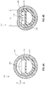
- FIGS. 4A, 4B, 5A, and 5B depict additional cross-sectional views of a portion of a catheter assembly, such as the catheter assembly of FIG. 2 .
- FIGS. 4A and 4B depict cross-sectional views of a catheter 210 that are transverse to the longitudinal length or longitudinal axis of the catheter 210
- FIGS. 5A and 5B depict cross-sectional views along a longitudinal length or longitudinal axis of the catheter 210
- FIGS. 4A and 5A depict a catheter 210 in a resting state, or a state in which a vacuum or reduced pressure is not being applied to the second lumen 218 of the catheter 210
- FIGS. 4B and 5B depict the catheter 210 in an aspiration state, or a state in which a vacuum or reduced pressure is being applied to the second lumen 218 of the catheter 210 (as indicated by the reference arrows).
- a vacuum or reduced pressure can cause a portion of the sheath 220 to be drawn or to otherwise sag inwards towards and/or through the distal opening 224 .
- the catheter 210 and/or sheath 220 are configured such that the sheath 220 is restricted from clogging or otherwise blocking the lumen 218 .
- the catheter 210 and sheath 220 are configured such that the sheath 220 is restricted from being drawn into contact with the inner or back wall 213 of the lumen 218 .
- the distal openings 224 can be sized such that the sheath 220 is supported by the walls of the distal openings 224 , preventing the sheath 220 from coming in contact with the inner wall 213 .
- one or more lengths L 1 and/or L 2 (or a diameter if circular) of the distal openings 224 can also be selected such that the walls of the distal openings 224 can support the sheath 220 and prevent the sheath 220 from being drawn inside the lumen 218 and into contact with the inner wall 213 .
- the sheath 220 can be prevented from being drawn in a distance of L SAG .
- the openings 224 are circular, such that L 1 is substantially equal to L 2 .
- the lengths of L 1 and L 2 are different.
- the openings 224 can be non-circular, such as in the shape of an oval, a square, a slot, or a slit, etc.
- the material of the sheath 220 is selected such that the sheath 220 comprises a stiffness that prevents the sheath 220 from being drawn into contact with the inner wall 213 .
- the sheath 220 comprises a thickness that prevents the sheath 220 from being drawn into contact with the inner wall 213 of the lumen 218 .
- FIG. 6 depicts a catheter assembly 300 in accordance with another embodiment of the present disclosure.
- the catheter 310 comprises a preformed catheter 310 .
- a preformed catheter 310 can be described as a catheter 310 that assumes a predetermined, non-linear shape in its relaxed state.
- the catheter 310 assumes a specified shape that is non-linear when not being acted upon by one or more outside forces.
- a preformed catheter 310 can re-assume or at least partially recover to its predetermined, non-linear shape after temporary application of an outside force.
- the relaxed state can be used in reference to a state of the catheter 310 prior to and/or after deployment in a body cavity.
- the catheter is not preformed.
- the catheter can be substantially linear, such as can be represented by the catheter assembly depicted in FIG. 2 .
- the preformed catheter 310 can assume any variety of shapes in its relaxed state, including three-dimensional shapes in which portions of the catheter 310 extend along two or more of the X, Y, and Z axes.
- the catheter 310 extends along a distance L Z in the Z axis, a distance L Y in the Y axis, and a distance L X in the X axis.
- the preformed catheter 310 can assume a helical, a spiral, or a coil-like shape in its relaxed state (such as is shown in FIG. 6 ).
- the preformed catheter 310 can assume a non-defined three-dimensional shape in its relaxed state (such as is shown in FIG. 7 ).
- the preformed catheter 310 comprises a resilient material such that it can be temporarily straightened or substantially straightened for insertion into the body of a patient.
- the preformed catheter 310 can be in a first state prior to deployment, wherein the catheter 310 comprises a predetermined shape in the first state.
- the preformed catheter 310 can then be configured to transition to a second state during deployment (e.g., an introduction or insertion state).
- the preformed catheter 31 can be straightened or substantially straightened along a guide wire, stylet, or with another insertion aid.
- an outer insertion sheath or cover can be disposed over the catheter 310 that can force or otherwise cause the catheter 310 to assume a linear or substantially linear shape for insertion.
- a guide wire, stylet, or insertion aid e.g., an outer insertion sheath
- a non-linear shape e.g., a hooked or arcuate shape
- the preformed catheter 310 can resiliently assume a third state as the catheter 310 (or the material of the catheter 310 ) at least partially recovers (or tries to recover) to its predetermined shape (or the configuration of the first state) as it transitions from a non-relaxed state (e.g., an insertion state) to a relaxed state (e.g., an inserted state).
- the third state may be slightly (or substantially) different than the predetermined shape of the first state, at least in part due to the constraints of the patient's 10 anatomy within which the catheter is disposed.
- the catheter 310 may also not perfectly recover to the configuration of the first state.
- the configuration of the catheter 310 in the third state e.g., a deployed state
- the configuration of the catheter 310 in the third state can be described as being in an intermediate configuration that is between the first state (e.g., a state prior to deployment) and the second state (e.g., a deployment state).
- the preformed catheter 310 is capable of being straightened or substantially straightened as it is inserted into the body of a patient without an insertion aid. After insertion into the body of a patient, the preformed catheter 310 can resiliently assume (or at least partially assume) its predetermined shape as it transitions from a non-relaxed state (insertion state) to a relaxed state (inserted state).
- the preformed catheter 310 can be configured to fill or extend through various regions within the body cavity. Further, the preformed shape can be configured such that the distal openings 324 are disposed in various regions of the body cavity of the patient. Having distal openings 324 disposed in different regions is advantageous in many ways. For example, as can be appreciated, one or more gases in the body cavity (e.g., stomach) of the patient can move into an upper region of the stomach, while the lower region can be filled with liquid or solid substances (e.g., food). Further, as the patient is moved (e.g., from an upright position to a horizontal or laying down position) the location of the one or more gases can also change.
- the body cavity e.g., stomach
- liquid or solid substances e.g., food
- distal openings 324 disposed in multiple locations can help proper venting or aspiration, as one or more distal openings 324 can be kept out of the liquid region and in contact with a gas filled region, regardless of the orientation or position of the patient.
- one or more openings e.g., a first distal opening
- one or more other distal openings e.g., a second distal opening
- the preformed catheter assumes a helical, a spiral, or a coil-like shape in its relaxed state.
- the distal openings 324 can be disposed in one or more of the upper region, lower region, left region, and right region of the body cavity (e.g., stomach) of the patient, allowing gases to be withdrawn from any one of such regions.
- one or more dimensions of the preformed geometry exceeds the dimensions of the body cavity, causing the preformed catheter 310 to position or otherwise dispose itself in the outer (or peripheral) regions of the body cavity due to being constrained by the cavity walls.
- the one or more distal openings can be disposed in one or more regions of the body cavity (e.g., stomach), such as the upper region, lower region, left region, and right region, without the use of a preformed catheter.
- the one or more distal openings are disposed on the catheter such that at least one opening is disposed in an upper region of the body cavity (e.g., stomach) following insertion in a patient.
- the one or more distal openings can be disposed along a length of the catheter (e.g., along the intermediate section of the catheter) such that one or more distal openings are disposed in at least two regions of the body cavity (e.g., stomach).
- the one or more distal openings can be disposed along a length of the catheter such that at least one opening is disposed in a lower or intermediate region of the body cavity (e.g., stomach) and at least one opening is disposed in an upper region of the body cavity (e.g., stomach).
- bending and/or folding of the catheter following insertion into the body cavity can also cause the one or more distal openings to be disposed in one or more regions of (or throughout) the body cavity.
- FIG. 7 depicts a preformed catheter 410 portion of a catheter assembly 400 in accordance with an embodiment of the present disclosure.
- the catheter assembly 400 can comprise a preformed catheter 410 having openings 424 disposed in a variety of locations.
- the preformed catheter 410 also assumes an undefined three-dimensional shape. Any variety of non-linear shapes (e.g., non-linear three-dimensional shapes) is contemplated.
- FIG. 8 is a perspective view of a multi-lumen catheter assembly 500 , according to another embodiment of the present disclosure.
- the catheter assembly 500 can be disposed such that the distal end 512 of the catheter 510 is disposed in a bowel 14 or intestine of the patient 10 .
- the delivery of food can be to a bowel 14 or intestine region.
- one or more distal openings 524 can be disposed in the stomach 12 , such that venting and/or aspiration can simultaneously occur from within the stomach 12 region.
- One or more distal openings 524 can also be disposed in the bowel 14 region, if desired.
- FIG. 9 is a perspective view of a multi-lumen catheter assembly 600 , according to yet another embodiment of the present disclosure.
- an enteral connector 642 is used.
- Other types of connectors that satisfy standards and/or international standards (e.g., ISO 80369-3) for feeding tubes and catheters can also be used.
- various connectors e.g., enteral connectors 642
- an enteral connector 624 can be coupled to a first extension leg 640 .
- the enteral connector 642 can also be configured to couple to a feed system, and can be associated with the delivery of food through the multi-lumen catheter 610 .
- the method 700 comprises a step 710 of inserting the distal end of a multi-lumen catheter having a feeding lumen and an aspiration lumen through a nasal (or oral) passage and into a stomach (or bowel) of a patient.
- the method 700 can further including a step 720 of coupling or otherwise connecting the proximal end of the aspiration lumen to a vacuum source, wherein the vacuum source is configured to reduce pressure in at least a portion of the aspiration lumen, causing one or more gases to be drawn from the patient into the aspiration lumen.
- the proximal end of the aspiration lumen is left open to vent.
- the method 700 can comprise a step 740 of coupling or otherwise connecting the feeding lumen to a feed system, and a step 750 of delivering food from the feed system through the feeding lumen and into the patient while simultaneously venting or aspirating gases from the patient through the aspiration lumen.
- the method further comprises a step 760 of uncoupling the feeding lumen from the feed system.
- the aspiration lumen can be left venting or aspirating after the feed system has been uncoupled.
- the method can further comprise a step 770 of repeating the feeding steps 740 , 750 , and 760 .
- the method can comprise an alternate feeding step in place of, or in addition to, feeding steps 740 , 750 , and 760 .
- the method can comprise a step 730 of feeding the patient through oral and esophageal passages while venting or aspirating gases through the aspiration lumen.
- the method can also comprise a step 780 of removing the distal end of the catheter through the nasal (or oral) passage of the patient. Other method steps can also be employed.
- the embodiments and disclosure herein can be applied to various types and/or sizes of multi-lumen catheters.
- the multi-lumen catheters have an outside diameter that is 10 french, 8 french, or 6 french or less. Other sizes of catheters can also be used.
- the various components of the catheter assemblies can be made of one or more polymeric materials. Different polymeric materials can also be used for different components depending on, for example, the desired stiffness or flexibility of a given component.
- the various components can also be made in various ways, including but not limited to extrusion techniques, injection molding techniques, and other techniques known in the art.
- references to approximations are made throughout this specification, such as by use of the terms “substantially.”
- the value, feature, or characteristic may be specified without approximation.
- qualifiers such as “about” and “substantially” are used, these terms include within their scope the qualified words in the absence of their qualifiers.
- the term “substantially linear” is recited with respect to a feature, it is understood that in further embodiments, the feature can have a precisely linear configuration.
Abstract
Description
Claims (17)
Priority Applications (1)
| Application Number | Priority Date | Filing Date | Title |
|---|---|---|---|
| US16/003,974 US11291611B2 (en) | 2017-06-09 | 2018-06-08 | Multi-lumen gastrointestinal feeding and aspirating catheter assemblies |
Applications Claiming Priority (2)
| Application Number | Priority Date | Filing Date | Title |
|---|---|---|---|
| US201762517621P | 2017-06-09 | 2017-06-09 | |
| US16/003,974 US11291611B2 (en) | 2017-06-09 | 2018-06-08 | Multi-lumen gastrointestinal feeding and aspirating catheter assemblies |
Publications (2)
| Publication Number | Publication Date |
|---|---|
| US20180353390A1 US20180353390A1 (en) | 2018-12-13 |
| US11291611B2 true US11291611B2 (en) | 2022-04-05 |
Family
ID=64562179
Family Applications (1)
| Application Number | Title | Priority Date | Filing Date |
|---|---|---|---|
| US16/003,974 Active 2039-04-24 US11291611B2 (en) | 2017-06-09 | 2018-06-08 | Multi-lumen gastrointestinal feeding and aspirating catheter assemblies |
Country Status (1)
| Country | Link |
|---|---|
| US (1) | US11291611B2 (en) |
Cited By (1)
| Publication number | Priority date | Publication date | Assignee | Title |
|---|---|---|---|---|
| US20210236793A1 (en) * | 2020-02-05 | 2021-08-05 | Yi-Ching Liu | Multi-tube adapter |
Families Citing this family (2)
| Publication number | Priority date | Publication date | Assignee | Title |
|---|---|---|---|---|
| US20180311417A1 (en) * | 2015-11-05 | 2018-11-01 | Cedars-Sinai Medical Center | Pharyngeal-enteric tube combination |
| TWI699224B (en) * | 2019-10-18 | 2020-07-21 | 陳嘉琦 | Structural improvement of nasogastric tube |
Citations (41)
| Publication number | Priority date | Publication date | Assignee | Title |
|---|---|---|---|---|
| US3572315A (en) | 1968-11-26 | 1971-03-23 | John S Cullen | Intravascular catheter with gas-permeable tip |
| US3658053A (en) * | 1969-08-28 | 1972-04-25 | Scient Research Instr Corp | Catheter for use in detecting dissolved gas in fluids such as blood |
| US3893448A (en) | 1973-11-26 | 1975-07-08 | John W Brantigan | Catheter device for use in detecting gas in body fluids and tissue |
| US3981297A (en) | 1975-03-03 | 1976-09-21 | Sorenson Research Co., Inc. | Gas sampling catheter assembly and method |
| US4016864A (en) | 1974-08-01 | 1977-04-12 | Airco, Inc. | Blood gas catheter |
| US4221567A (en) | 1977-12-23 | 1980-09-09 | Intermountain Health Care | Sampling and determination of diffusible chemical substances |
| US4274417A (en) | 1978-09-22 | 1981-06-23 | National Research Development Corporation | Instruments for use in the measurement of gases in body fluids |
| US4340615A (en) * | 1979-06-07 | 1982-07-20 | The Medishield Corporation Limited | Apparatus for analysis of absorbed gases |
| US4543089A (en) | 1981-10-16 | 1985-09-24 | Gerald Moss | Gastrointestinal feeding and aspirating device for use in treating patients |
| US4642092A (en) | 1984-12-10 | 1987-02-10 | Gerald Moss | Gastrointestinal aspirating device with suction breakers |
| US4901727A (en) | 1988-05-05 | 1990-02-20 | The Boc Group, Inc. | Micro-probe for gas sampling |
| US5334167A (en) | 1993-11-19 | 1994-08-02 | Cocanower David A | Modified nasogastric tube for use in enteral feeding |
| US5401241A (en) | 1992-05-07 | 1995-03-28 | Inamed Development Co. | Duodenal intubation catheter |
| US5417664A (en) * | 1993-10-25 | 1995-05-23 | C. R. Bard, Inc. | Reflux containment device for nasogastric tubes |
| US5423320A (en) | 1993-04-20 | 1995-06-13 | Argus Critical Care, Inc. | Air tonometry method and apparatus for measuring intraluminal gastrointestinal pCO2 and pO2 |
| US5460603A (en) | 1993-04-08 | 1995-10-24 | Massachusetts Institute Of Technology | Method and apparatus for preventing back flow in gastroenterological feeding system |
| US5520662A (en) | 1994-09-09 | 1996-05-28 | Moss; Gerald | Gastrointestinal aspirating and feeding device with removable sleeve |
| US5807311A (en) | 1996-11-29 | 1998-09-15 | Palestrant; Aubrey M. | Dialysis catheter having rigid and collapsible lumens and related method |
| US5832920A (en) | 1995-10-04 | 1998-11-10 | Smiths Industries Public Limited Co. | Tracheal tube with integral suction lumen |
| US6029076A (en) | 1991-06-20 | 2000-02-22 | Instrumentarium Corp. | Remote sensing tonometric catheter method |
| US6447472B1 (en) | 2000-10-19 | 2002-09-10 | Gerald Moss | Method and pump apparatus for combined gastro-intestinal feeding and aspiration |
| US20030144623A1 (en) * | 2002-01-29 | 2003-07-31 | Heath Kevin R. | Occlusion-resistant catheter |
| US6659974B1 (en) | 2000-10-19 | 2003-12-09 | Gerald Moss | Single lumen gastro-intestinal feeding-decompression tubes |
| US20040034320A1 (en) * | 2002-08-13 | 2004-02-19 | Burnett Daniel Rogers | Anti-reflux feeding tube |
| US20040167463A1 (en) | 2003-02-21 | 2004-08-26 | Zawacki John A. | Multi-lumen catheter with separate distal tips |
| US20050124932A1 (en) | 2003-12-05 | 2005-06-09 | Kimberly-Clark Worldwide, Inc. | Venting catheter |
| US20050124935A1 (en) | 2003-12-05 | 2005-06-09 | Kimberly-Clark Worldwide, Inc. | Venting adapter for feeding device |
| US20050171468A1 (en) * | 2004-02-04 | 2005-08-04 | Wood Scott D. | Gastric aspirate intestinal feeding tube |
| US6949092B1 (en) | 2003-04-18 | 2005-09-27 | Gerald Moss | Continuous feeding and decompressing device, tube assembly, and methods |
| US20060270974A1 (en) * | 2005-05-16 | 2006-11-30 | Kerberos Proximal Solutions, Inc. | Methods and systems for filtering aspirated materials |
| US20080077043A1 (en) | 2006-08-25 | 2008-03-27 | Manu Malbrain | Enteral feeding catheter and apparatus for determining the intra-abdominal pressure of a patient |
| US7404807B2 (en) | 2006-03-17 | 2008-07-29 | James Josiah Callaway | Pediatric nasal gastric vent tube |
| US20090048559A1 (en) | 2007-08-14 | 2009-02-19 | Kurt William Albert Grathwohl | Dual lumen gastrointestinal feeding and aspirating device |
| US20090318897A1 (en) | 2008-06-20 | 2009-12-24 | Cook Critical Care Incorporated | Gastrojejunal feeding assembly |
| US20110196316A1 (en) | 2010-02-08 | 2011-08-11 | Quinn David G | Catheter |
| US20120283627A1 (en) | 2011-05-06 | 2012-11-08 | Gerald Moss | Method for combined gastrointestional feeding and aspiration |
| US20130324971A1 (en) | 2012-06-01 | 2013-12-05 | Radius International, Inc. | Corporeal catheter |
| US8784602B2 (en) | 2007-09-12 | 2014-07-22 | Cook Medical Technologies Llc | Balloon catheter for delivering a therapeutic agent |
| US20140276633A1 (en) | 2013-03-15 | 2014-09-18 | Nadarasa Visveshwara | Fluid and nutrition delivery device and method of use |
| US20140323966A1 (en) | 2013-04-30 | 2014-10-30 | Kimberly-Clark Worldwide, Inc. | Gastric jejunal tube with an enlarged jejunal lumen |
| US9028441B2 (en) | 2011-09-08 | 2015-05-12 | Corpak Medsystems, Inc. | Apparatus and method used with guidance system for feeding and suctioning |
-
2018
- 2018-06-08 US US16/003,974 patent/US11291611B2/en active Active
Patent Citations (45)
| Publication number | Priority date | Publication date | Assignee | Title |
|---|---|---|---|---|
| US3572315A (en) | 1968-11-26 | 1971-03-23 | John S Cullen | Intravascular catheter with gas-permeable tip |
| US3658053A (en) * | 1969-08-28 | 1972-04-25 | Scient Research Instr Corp | Catheter for use in detecting dissolved gas in fluids such as blood |
| US3893448A (en) | 1973-11-26 | 1975-07-08 | John W Brantigan | Catheter device for use in detecting gas in body fluids and tissue |
| US4016864A (en) | 1974-08-01 | 1977-04-12 | Airco, Inc. | Blood gas catheter |
| US3981297A (en) | 1975-03-03 | 1976-09-21 | Sorenson Research Co., Inc. | Gas sampling catheter assembly and method |
| US4221567A (en) | 1977-12-23 | 1980-09-09 | Intermountain Health Care | Sampling and determination of diffusible chemical substances |
| US4274417A (en) | 1978-09-22 | 1981-06-23 | National Research Development Corporation | Instruments for use in the measurement of gases in body fluids |
| US4340615A (en) * | 1979-06-07 | 1982-07-20 | The Medishield Corporation Limited | Apparatus for analysis of absorbed gases |
| US4543089A (en) | 1981-10-16 | 1985-09-24 | Gerald Moss | Gastrointestinal feeding and aspirating device for use in treating patients |
| US4642092A (en) | 1984-12-10 | 1987-02-10 | Gerald Moss | Gastrointestinal aspirating device with suction breakers |
| US4901727A (en) | 1988-05-05 | 1990-02-20 | The Boc Group, Inc. | Micro-probe for gas sampling |
| US6029076A (en) | 1991-06-20 | 2000-02-22 | Instrumentarium Corp. | Remote sensing tonometric catheter method |
| US5401241A (en) | 1992-05-07 | 1995-03-28 | Inamed Development Co. | Duodenal intubation catheter |
| US5460603A (en) | 1993-04-08 | 1995-10-24 | Massachusetts Institute Of Technology | Method and apparatus for preventing back flow in gastroenterological feeding system |
| US5423320A (en) | 1993-04-20 | 1995-06-13 | Argus Critical Care, Inc. | Air tonometry method and apparatus for measuring intraluminal gastrointestinal pCO2 and pO2 |
| US5417664A (en) * | 1993-10-25 | 1995-05-23 | C. R. Bard, Inc. | Reflux containment device for nasogastric tubes |
| US5334167A (en) | 1993-11-19 | 1994-08-02 | Cocanower David A | Modified nasogastric tube for use in enteral feeding |
| US5520662A (en) | 1994-09-09 | 1996-05-28 | Moss; Gerald | Gastrointestinal aspirating and feeding device with removable sleeve |
| US5832920A (en) | 1995-10-04 | 1998-11-10 | Smiths Industries Public Limited Co. | Tracheal tube with integral suction lumen |
| US5807311A (en) | 1996-11-29 | 1998-09-15 | Palestrant; Aubrey M. | Dialysis catheter having rigid and collapsible lumens and related method |
| US6659974B1 (en) | 2000-10-19 | 2003-12-09 | Gerald Moss | Single lumen gastro-intestinal feeding-decompression tubes |
| US6447472B1 (en) | 2000-10-19 | 2002-09-10 | Gerald Moss | Method and pump apparatus for combined gastro-intestinal feeding and aspiration |
| US20030144623A1 (en) * | 2002-01-29 | 2003-07-31 | Heath Kevin R. | Occlusion-resistant catheter |
| US20040034320A1 (en) * | 2002-08-13 | 2004-02-19 | Burnett Daniel Rogers | Anti-reflux feeding tube |
| US20040167463A1 (en) | 2003-02-21 | 2004-08-26 | Zawacki John A. | Multi-lumen catheter with separate distal tips |
| US6949092B1 (en) | 2003-04-18 | 2005-09-27 | Gerald Moss | Continuous feeding and decompressing device, tube assembly, and methods |
| US20050124932A1 (en) | 2003-12-05 | 2005-06-09 | Kimberly-Clark Worldwide, Inc. | Venting catheter |
| US20050124935A1 (en) | 2003-12-05 | 2005-06-09 | Kimberly-Clark Worldwide, Inc. | Venting adapter for feeding device |
| US20050171468A1 (en) * | 2004-02-04 | 2005-08-04 | Wood Scott D. | Gastric aspirate intestinal feeding tube |
| US20060270974A1 (en) * | 2005-05-16 | 2006-11-30 | Kerberos Proximal Solutions, Inc. | Methods and systems for filtering aspirated materials |
| US7404807B2 (en) | 2006-03-17 | 2008-07-29 | James Josiah Callaway | Pediatric nasal gastric vent tube |
| US20080077043A1 (en) | 2006-08-25 | 2008-03-27 | Manu Malbrain | Enteral feeding catheter and apparatus for determining the intra-abdominal pressure of a patient |
| US20090048559A1 (en) | 2007-08-14 | 2009-02-19 | Kurt William Albert Grathwohl | Dual lumen gastrointestinal feeding and aspirating device |
| US8257306B2 (en) | 2007-08-14 | 2012-09-04 | Grathwohl Kurt W | Dual lumen gastrointestinal feeding and aspirating device |
| US8784602B2 (en) | 2007-09-12 | 2014-07-22 | Cook Medical Technologies Llc | Balloon catheter for delivering a therapeutic agent |
| US20090318897A1 (en) | 2008-06-20 | 2009-12-24 | Cook Critical Care Incorporated | Gastrojejunal feeding assembly |
| US20110196290A1 (en) | 2010-02-08 | 2011-08-11 | Quinn David G | Jejunal feeding catheter |
| US20110196316A1 (en) | 2010-02-08 | 2011-08-11 | Quinn David G | Catheter |
| US20120283627A1 (en) | 2011-05-06 | 2012-11-08 | Gerald Moss | Method for combined gastrointestional feeding and aspiration |
| US9028441B2 (en) | 2011-09-08 | 2015-05-12 | Corpak Medsystems, Inc. | Apparatus and method used with guidance system for feeding and suctioning |
| US20130324971A1 (en) | 2012-06-01 | 2013-12-05 | Radius International, Inc. | Corporeal catheter |
| US20130324916A1 (en) | 2012-06-01 | 2013-12-05 | Radius International, Inc. | Corporeal catheters |
| US20140276633A1 (en) | 2013-03-15 | 2014-09-18 | Nadarasa Visveshwara | Fluid and nutrition delivery device and method of use |
| US20140323966A1 (en) | 2013-04-30 | 2014-10-30 | Kimberly-Clark Worldwide, Inc. | Gastric jejunal tube with an enlarged jejunal lumen |
| US9427378B2 (en) | 2013-04-30 | 2016-08-30 | Avent, Inc. | Gastric jejunal tube with an enlarged jejunal lumen |
Non-Patent Citations (1)
| Title |
|---|
| Silk , et al., "Dual-Purpose Gastric Decompression and Enteral Feeding Tubes Rationale and Design of Novel Nasogastric and Nasogastrojejunal Tubes", Journal of Parenteral and Enteral Nutrition, vol. 39, No. 5, Jul. 2015 531-543. |
Cited By (1)
| Publication number | Priority date | Publication date | Assignee | Title |
|---|---|---|---|---|
| US20210236793A1 (en) * | 2020-02-05 | 2021-08-05 | Yi-Ching Liu | Multi-tube adapter |
Also Published As
| Publication number | Publication date |
|---|---|
| US20180353390A1 (en) | 2018-12-13 |
Similar Documents
| Publication | Publication Date | Title |
|---|---|---|
| US11291611B2 (en) | Multi-lumen gastrointestinal feeding and aspirating catheter assemblies | |
| US11433001B2 (en) | System, apparatus and method employed with enteral systems | |
| US7578803B2 (en) | Multifunction adaptor for an open-ended catheter | |
| US20080110468A1 (en) | Method and apparatus for preventing occlusion of a tracheal tube suction lumen | |
| JP4420926B2 (en) | Catheter with valve | |
| US8251923B2 (en) | Device for introducing a catheter guide wire into a vessel | |
| AU2005234786B2 (en) | Dual purpose adapter | |
| US4403983A (en) | Dual lumen subclavian cannula | |
| US8075521B2 (en) | Catheter | |
| JP3766110B2 (en) | Catheter guide wire introduction device | |
| JP7245596B2 (en) | Suction device for medical device and medical device system including suction device | |
| US20090192448A1 (en) | Oral gastric lavage apparatus | |
| CN107913461A (en) | With the submissive pipe joint for autotomying suture needle | |
| CN109475668B (en) | Catheter dynamic tip occlusion | |
| AU2002364299A1 (en) | Low profile adaptor for use with a medical catheter | |
| CN103124581A (en) | Enteral feeding assembly | |
| US9597471B2 (en) | Devices and methods for airway suctioning | |
| US10945926B2 (en) | Locking enteral feeding system | |
| CA2918461A1 (en) | Catheter-positioning slide cover clamp assembly | |
| US8882725B2 (en) | Enteral feeding connector | |
| EP4000590A1 (en) | Feeding tube | |
| US20210220591A1 (en) | Suction catheter with detachable connector and methods thereof | |
| JP2024004359A (en) | trocar catheter |
Legal Events
| Date | Code | Title | Description |
|---|---|---|---|
| FEPP | Fee payment procedure |
Free format text: ENTITY STATUS SET TO UNDISCOUNTED (ORIGINAL EVENT CODE: BIG.); ENTITY STATUS OF PATENT OWNER: SMALL ENTITY |
|
| FEPP | Fee payment procedure |
Free format text: ENTITY STATUS SET TO SMALL (ORIGINAL EVENT CODE: SMAL); ENTITY STATUS OF PATENT OWNER: SMALL ENTITY |
|
| AS | Assignment |
Owner name: IHC HEALTH SERVICES, INC., UTAH Free format text: ASSIGNMENT OF ASSIGNORS INTEREST;ASSIGNOR:ORR, TROY J.;REEL/FRAME:046357/0624 Effective date: 20180523 Owner name: ELMONT, JENNIFER OWENS, UTAH Free format text: ASSIGNMENT OF ASSIGNORS INTEREST;ASSIGNOR:IHC HEALTH SERVICES, INC.;REEL/FRAME:046551/0796 Effective date: 20180621 |
|
| STPP | Information on status: patent application and granting procedure in general |
Free format text: DOCKETED NEW CASE - READY FOR EXAMINATION |
|
| STPP | Information on status: patent application and granting procedure in general |
Free format text: NON FINAL ACTION MAILED |
|
| STPP | Information on status: patent application and granting procedure in general |
Free format text: RESPONSE TO NON-FINAL OFFICE ACTION ENTERED AND FORWARDED TO EXAMINER |
|
| STPP | Information on status: patent application and granting procedure in general |
Free format text: RESPONSE TO NON-FINAL OFFICE ACTION ENTERED AND FORWARDED TO EXAMINER |
|
| STPP | Information on status: patent application and granting procedure in general |
Free format text: FINAL REJECTION MAILED |
|
| STPP | Information on status: patent application and granting procedure in general |
Free format text: DOCKETED NEW CASE - READY FOR EXAMINATION |
|
| STPP | Information on status: patent application and granting procedure in general |
Free format text: NOTICE OF ALLOWANCE MAILED -- APPLICATION RECEIVED IN OFFICE OF PUBLICATIONS |
|
| AS | Assignment |
Owner name: SUNDANCE ENTERAL SOLUTIONS, LLC, UTAH Free format text: ASSIGNMENT OF ASSIGNORS INTEREST;ASSIGNORS:ELMONT, JENNIFER OWENS;MINTON, STEPHEN DENNIS;REEL/FRAME:059133/0774 Effective date: 20220222 |
|
| STPP | Information on status: patent application and granting procedure in general |
Free format text: PUBLICATIONS -- ISSUE FEE PAYMENT VERIFIED |
|
| STCF | Information on status: patent grant |
Free format text: PATENTED CASE |