US11286707B2 - Opening and closing system - Google Patents
Opening and closing system Download PDFInfo
- Publication number
- US11286707B2 US11286707B2 US16/530,868 US201916530868A US11286707B2 US 11286707 B2 US11286707 B2 US 11286707B2 US 201916530868 A US201916530868 A US 201916530868A US 11286707 B2 US11286707 B2 US 11286707B2
- Authority
- US
- United States
- Prior art keywords
- striker
- vehicle
- lamp
- pop
- vehicle user
- Prior art date
- Legal status (The legal status is an assumption and is not a legal conclusion. Google has not performed a legal analysis and makes no representation as to the accuracy of the status listed.)
- Active, expires
Links
Images


Classifications
-
- B—PERFORMING OPERATIONS; TRANSPORTING
- B60—VEHICLES IN GENERAL
- B60Q—ARRANGEMENT OF SIGNALLING OR LIGHTING DEVICES, THE MOUNTING OR SUPPORTING THEREOF OR CIRCUITS THEREFOR, FOR VEHICLES IN GENERAL
- B60Q1/00—Arrangement of optical signalling or lighting devices, the mounting or supporting thereof or circuits therefor
- B60Q1/26—Arrangement of optical signalling or lighting devices, the mounting or supporting thereof or circuits therefor the devices being primarily intended to indicate the vehicle, or parts thereof, or to give signals, to other traffic
- B60Q1/30—Arrangement of optical signalling or lighting devices, the mounting or supporting thereof or circuits therefor the devices being primarily intended to indicate the vehicle, or parts thereof, or to give signals, to other traffic for indicating rear of vehicle, e.g. by means of reflecting surfaces
-
- B—PERFORMING OPERATIONS; TRANSPORTING
- B60—VEHICLES IN GENERAL
- B60J—WINDOWS, WINDSCREENS, NON-FIXED ROOFS, DOORS, OR SIMILAR DEVICES FOR VEHICLES; REMOVABLE EXTERNAL PROTECTIVE COVERINGS SPECIALLY ADAPTED FOR VEHICLES
- B60J5/00—Doors
- B60J5/10—Doors arranged at the vehicle rear
- B60J5/101—Doors arranged at the vehicle rear for non-load transporting vehicles, i.e. family cars including vans
- B60J5/107—Doors arranged at the vehicle rear for non-load transporting vehicles, i.e. family cars including vans constructional details, e.g. about door frame, panels, materials used, reinforcements
-
- B—PERFORMING OPERATIONS; TRANSPORTING
- B60—VEHICLES IN GENERAL
- B60Q—ARRANGEMENT OF SIGNALLING OR LIGHTING DEVICES, THE MOUNTING OR SUPPORTING THEREOF OR CIRCUITS THEREFOR, FOR VEHICLES IN GENERAL
- B60Q1/00—Arrangement of optical signalling or lighting devices, the mounting or supporting thereof or circuits therefor
- B60Q1/02—Arrangement of optical signalling or lighting devices, the mounting or supporting thereof or circuits therefor the devices being primarily intended to illuminate the way ahead or to illuminate other areas of way or environments
- B60Q1/24—Arrangement of optical signalling or lighting devices, the mounting or supporting thereof or circuits therefor the devices being primarily intended to illuminate the way ahead or to illuminate other areas of way or environments for lighting other areas than only the way ahead
- B60Q1/247—Arrangement of optical signalling or lighting devices, the mounting or supporting thereof or circuits therefor the devices being primarily intended to illuminate the way ahead or to illuminate other areas of way or environments for lighting other areas than only the way ahead for illuminating the close surroundings of the vehicle, e.g. to facilitate entry or exit
-
- E—FIXED CONSTRUCTIONS
- E05—LOCKS; KEYS; WINDOW OR DOOR FITTINGS; SAFES
- E05B—LOCKS; ACCESSORIES THEREFOR; HANDCUFFS
- E05B81/00—Power-actuated vehicle locks
- E05B81/12—Power-actuated vehicle locks characterised by the function or purpose of the powered actuators
- E05B81/20—Power-actuated vehicle locks characterised by the function or purpose of the powered actuators for assisting final closing or for initiating opening
- E05B81/21—Power-actuated vehicle locks characterised by the function or purpose of the powered actuators for assisting final closing or for initiating opening with means preventing or detecting pinching of objects or body parts
-
- E—FIXED CONSTRUCTIONS
- E05—LOCKS; KEYS; WINDOW OR DOOR FITTINGS; SAFES
- E05B—LOCKS; ACCESSORIES THEREFOR; HANDCUFFS
- E05B83/00—Vehicle locks specially adapted for particular types of wing or vehicle
- E05B83/16—Locks for luggage compartments, car boot lids or car bonnets
- E05B83/18—Locks for luggage compartments, car boot lids or car bonnets for car boot lids or rear luggage compartments
-
- E—FIXED CONSTRUCTIONS
- E05—LOCKS; KEYS; WINDOW OR DOOR FITTINGS; SAFES
- E05F—DEVICES FOR MOVING WINGS INTO OPEN OR CLOSED POSITION; CHECKS FOR WINGS; WING FITTINGS NOT OTHERWISE PROVIDED FOR, CONCERNED WITH THE FUNCTIONING OF THE WING
- E05F15/00—Power-operated mechanisms for wings
- E05F15/70—Power-operated mechanisms for wings with automatic actuation
- E05F15/73—Power-operated mechanisms for wings with automatic actuation responsive to movement or presence of persons or objects
-
- B—PERFORMING OPERATIONS; TRANSPORTING
- B60—VEHICLES IN GENERAL
- B60Q—ARRANGEMENT OF SIGNALLING OR LIGHTING DEVICES, THE MOUNTING OR SUPPORTING THEREOF OR CIRCUITS THEREFOR, FOR VEHICLES IN GENERAL
- B60Q2400/00—Special features or arrangements of exterior signal lamps for vehicles
- B60Q2400/40—Welcome lights, i.e. specific or existing exterior lamps to assist leaving or approaching the vehicle
-
- E—FIXED CONSTRUCTIONS
- E05—LOCKS; KEYS; WINDOW OR DOOR FITTINGS; SAFES
- E05B—LOCKS; ACCESSORIES THEREFOR; HANDCUFFS
- E05B81/00—Power-actuated vehicle locks
- E05B81/02—Power-actuated vehicle locks characterised by the type of actuators used
- E05B81/04—Electrical
- E05B81/06—Electrical using rotary motors
-
- E—FIXED CONSTRUCTIONS
- E05—LOCKS; KEYS; WINDOW OR DOOR FITTINGS; SAFES
- E05B—LOCKS; ACCESSORIES THEREFOR; HANDCUFFS
- E05B81/00—Power-actuated vehicle locks
- E05B81/12—Power-actuated vehicle locks characterised by the function or purpose of the powered actuators
- E05B81/14—Power-actuated vehicle locks characterised by the function or purpose of the powered actuators operating on bolt detents, e.g. for unlatching the bolt
-
- E—FIXED CONSTRUCTIONS
- E05—LOCKS; KEYS; WINDOW OR DOOR FITTINGS; SAFES
- E05F—DEVICES FOR MOVING WINGS INTO OPEN OR CLOSED POSITION; CHECKS FOR WINGS; WING FITTINGS NOT OTHERWISE PROVIDED FOR, CONCERNED WITH THE FUNCTIONING OF THE WING
- E05F15/00—Power-operated mechanisms for wings
- E05F15/70—Power-operated mechanisms for wings with automatic actuation
- E05F15/73—Power-operated mechanisms for wings with automatic actuation responsive to movement or presence of persons or objects
- E05F2015/765—Power-operated mechanisms for wings with automatic actuation responsive to movement or presence of persons or objects using optical sensors
-
- E—FIXED CONSTRUCTIONS
- E05—LOCKS; KEYS; WINDOW OR DOOR FITTINGS; SAFES
- E05Y—INDEXING SCHEME RELATING TO HINGES OR OTHER SUSPENSION DEVICES FOR DOORS, WINDOWS OR WINGS AND DEVICES FOR MOVING WINGS INTO OPEN OR CLOSED POSITION, CHECKS FOR WINGS AND WING FITTINGS NOT OTHERWISE PROVIDED FOR, CONCERNED WITH THE FUNCTIONING OF THE WING
- E05Y2201/00—Constructional elements; Accessories therefore
- E05Y2201/20—Brakes; Disengaging means, e.g. clutches; Holders, e.g. locks; Stops; Accessories therefore
- E05Y2201/218—Holders
- E05Y2201/22—Locks
-
- E—FIXED CONSTRUCTIONS
- E05—LOCKS; KEYS; WINDOW OR DOOR FITTINGS; SAFES
- E05Y—INDEXING SCHEME RELATING TO HINGES OR OTHER SUSPENSION DEVICES FOR DOORS, WINDOWS OR WINGS AND DEVICES FOR MOVING WINGS INTO OPEN OR CLOSED POSITION, CHECKS FOR WINGS AND WING FITTINGS NOT OTHERWISE PROVIDED FOR, CONCERNED WITH THE FUNCTIONING OF THE WING
- E05Y2400/00—Electronic control; Power supply; Power or signal transmission; User interfaces
- E05Y2400/80—User interfaces
- E05Y2400/85—User input means
- E05Y2400/852—Sensors
- E05Y2400/856—Actuation thereof
- E05Y2400/858—Actuation thereof by body parts
- E05Y2400/86—Actuation thereof by body parts by hand
-
- E—FIXED CONSTRUCTIONS
- E05—LOCKS; KEYS; WINDOW OR DOOR FITTINGS; SAFES
- E05Y—INDEXING SCHEME RELATING TO HINGES OR OTHER SUSPENSION DEVICES FOR DOORS, WINDOWS OR WINGS AND DEVICES FOR MOVING WINGS INTO OPEN OR CLOSED POSITION, CHECKS FOR WINGS AND WING FITTINGS NOT OTHERWISE PROVIDED FOR, CONCERNED WITH THE FUNCTIONING OF THE WING
- E05Y2800/00—Details, accessories and auxiliary operations not otherwise provided for
- E05Y2800/10—Additional functions
- E05Y2800/106—Lighting
-
- E—FIXED CONSTRUCTIONS
- E05—LOCKS; KEYS; WINDOW OR DOOR FITTINGS; SAFES
- E05Y—INDEXING SCHEME RELATING TO HINGES OR OTHER SUSPENSION DEVICES FOR DOORS, WINDOWS OR WINGS AND DEVICES FOR MOVING WINGS INTO OPEN OR CLOSED POSITION, CHECKS FOR WINGS AND WING FITTINGS NOT OTHERWISE PROVIDED FOR, CONCERNED WITH THE FUNCTIONING OF THE WING
- E05Y2900/00—Application of doors, windows, wings or fittings thereof
- E05Y2900/50—Application of doors, windows, wings or fittings thereof for vehicles
- E05Y2900/53—Application of doors, windows, wings or fittings thereof for vehicles characterised by the type of wing
- E05Y2900/531—Doors
- E05Y2900/532—Back doors or end doors
-
- E—FIXED CONSTRUCTIONS
- E05—LOCKS; KEYS; WINDOW OR DOOR FITTINGS; SAFES
- E05Y—INDEXING SCHEME RELATING TO HINGES OR OTHER SUSPENSION DEVICES FOR DOORS, WINDOWS OR WINGS AND DEVICES FOR MOVING WINGS INTO OPEN OR CLOSED POSITION, CHECKS FOR WINGS AND WING FITTINGS NOT OTHERWISE PROVIDED FOR, CONCERNED WITH THE FUNCTIONING OF THE WING
- E05Y2900/00—Application of doors, windows, wings or fittings thereof
- E05Y2900/50—Application of doors, windows, wings or fittings thereof for vehicles
- E05Y2900/53—Application of doors, windows, wings or fittings thereof for vehicles characterised by the type of wing
- E05Y2900/548—Trunk lids
-
- F—MECHANICAL ENGINEERING; LIGHTING; HEATING; WEAPONS; BLASTING
- F21—LIGHTING
- F21S—NON-PORTABLE LIGHTING DEVICES; SYSTEMS THEREOF; VEHICLE LIGHTING DEVICES SPECIALLY ADAPTED FOR VEHICLE EXTERIORS
- F21S43/00—Signalling devices specially adapted for vehicle exteriors, e.g. brake lamps, direction indicator lights or reversing lights
Definitions
- the present disclosure relates to an opening and closing system for a door of a vehicle such as a motor vehicle.
- a vehicle door such as a trunk lid is kept closed by engagement of a lock device provided on the vehicle door with a striker device provided on a vehicle body.
- An unlocking switch of the lock device on the trunk lid is typically provided on a surface of the trunk lid that is externally hardly visible such as a downwardly facing surface of the trunk lid at a rear end thereof so as not to deteriorate the aesthetic external appearance of the vehicle.
- a vehicle user has to run a user's hand along the downwardly facing surface of the trunk lid to search for the unlocking switch or to bend a user's body to visually confirm the position of the unlocking switch when the vehicle user attempts to open the trunk lid.
- an opening and closing system that can make a vehicle user free from the complex and troublesome operation for unlocking the trunk lid.
- An opening and closing system described in Japanese Patent No. 6167713 includes a sensor, a control device, and a driving device configured to cause a trunk lit to pop up to open.
- a vehicle user lifts up one of a user's feet to place it underneath a lower portion of a vehicle body, and then, the sensor detects the foot of the vehicle user. This unlocks the trunk lid without involvement of the vehicle user who otherwise has to touch the unlocking switch.
- a vehicle user such as an old vehicle user, a female vehicle user in her pregnancy or a disabled vehicle user may have difficulty in lifting up the foot to place it underneath the lower portion of the vehicle body from time to time.
- the trunk lid is unlocked and is then caused to pop up to open after the occupant comes so close to the vehicle door as for the occupant to lift up a user's foot to place it underneath the lower portion of the vehicle body.
- the vehicle user has to keep waiting in front of the trunk lid from the trunk lid is unlocked until the trunk lid is caused to pop up to open. In this way, with the opening and closing system of PTL 1, there is still room for improvement in convenience.
- Illustrative aspects of the present disclosure provide an opening and closing system that can enhance the convenience.
- an opening and closing system comprising: a lock device provided on a vehicle door, the lock device being configured to lock the vehicle door in a closed state and to perform an unlocking operation; a striker device provided on a vehicle body, the striker device being configured to perform: a closing operation comprising moving the vehicle door to a closed position; and a pop-up operation comprising moving the vehicle door in an opening direction from the closed position to a pop-up position; a first human detection sensor configured to detect a vehicle user who enters a first area defined on a periphery of the vehicle body; at least one lamp visible by the vehicle user who enters the first area; and a control device configured to: control the unlocking operation of the lock device, the closing operation and the pop-up operation of the striker device, and switching on and off of the lamp; in a case the vehicle user is detected by the first human detection sensor, switch on the lamp; and in response to the lamp being switched on, start the controlling of the unlocking operation of the lock device
- the opening and closing system that can enhance the convenience may be provided.
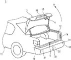
- FIG. 1 is a perspective view of an example of a vehicle for explaining an embodiment of the disclosure
- FIG. 2 is a block diagram of an opening and closing system mounted on the vehicle shown in FIG. 1 ;
- FIG. 3 is a perspective view of a lock device and a striker device of the opening and closing system shown in FIG. 2 ;
- FIG. 4 is a perspective view of the lock device alone shown in FIG. 3 ;
- FIG. 5 is a perspective view of a main part of the striker device shown in FIG. 3 ;
- FIG. 6 is a perspective view explaining a closing operation of the striker device shown in FIG. 5 ;
- FIG. 7 is a perspective view explaining a pop-up operation of the striker device shown in FIG. 5 ;
- FIGS. 8A and 8B show a flow chart of processing executed by a control device of the opening and closing system shown in FIG. 2 ;
- FIG. 9 is a schematic diagram explaining an operation of the opening and closing system shown in FIG. 2 .
- a traveling direction of a vehicle is referred to as a front-rear direction of the vehicle
- a direction at right angles to the front-rear direction of the vehicle in a plane parallel to a running plane of the vehicle is referred to as a width direction of the vehicle (or a left-right direction of the vehicle)
- a direction at right angles to the front-rear direction of the vehicle and the width direction of the vehicle is referred to as an up-down direction of the vehicle.
- FIG. 1 shows an example of a vehicle for explaining an embodiment of the disclosure
- FIG. 2 shows an example of an opening and closing system mounted on the vehicle shown in FIG. 1 .
- the vehicle 1 includes a trunk lid 2 as an example of a vehicle door.
- the trunk lid 2 is disposed on a lid frame 12 that constitutes an opening portion provided at a rear portion of a vehicle body 11 and is coupled to the vehicle body 11 in such a manner as to be opened in a direction indicated by an arrow A in FIG. 1 .
- An operation portion 15 is recessed into a central portion of a rear surface of the trunk lid 2 .
- a vehicle user opens the trunk lid 2 by, for example, placing a user's hand on the operation portion 15 .
- An opening and closing system 3 mounted on the vehicle 1 is used to open and close the trunk lid 2 .
- the opening and closing system 3 includes a lock device 4 , a striker device 6 , and a control device 9 .
- the lock device 4 is provided on the trunk lid 2
- the striker device 6 is provided on the lid frame 12 of the vehicle body 11 .
- the lock device 4 and the striker device 6 are brought into engagement with each other as the trunk lid 2 is closed, and the trunk lid 2 can be held in a closed state by the engagement of the lock device 4 with the striker device 6 .
- the lock device 4 is configured to lock the trunk lid 2 so as not to be opened and can be controlled in operation when performing an unlocking operation.
- the striker device 6 can be controlled in operation when performing a closing operation in which the trunk lid 2 is moved to a closed position and a pop-up operation in which the trunk lid 2 is moved from the closed position to a pop-up position when brought into engagement with the lock device 4 .
- the control device 9 controls the operation of the lock device 4 when the lock device 4 performs the unlocking operation, and the control device 9 controls the operation of the striker device 6 when the striker device 6 performs the closing operation and the operation of the striker device 6 when the striker device 6 performs the pop-up operation.
- the opening and closing system 3 includes a first human detection sensor 31 , a second human detection sensor 32 , a proximity sensor 33 , an illuminance sensor 34 , a foot lamp 35 , and an indicator lamp.
- the first human detection sensor 31 detects the vehicle user when the vehicle user enters a first area A 1 set on a periphery of the vehicle body 11 .
- the second human detection sensor 32 detects the vehicle user when the vehicle user enters a second area A 2 set on a periphery of the trunk lid 2 .
- the first area A 1 is set, for example, so as to expand to the rear and the left and right of the vehicle body 11 .
- the second area A 2 is set, for example, so as not only to expand to the rear of the trunk lid 2 but also to be included in the first area A 1 .
- the first human detection sensor 31 and the second human detection sensor 32 are made up, for example, of an infrared sensor, an ultrasonic sensor, or the like and are provided, for example, on a rear bumper 13 of the vehicle body 11 .
- the proximity sensor 33 detects in a noncontacting fashion that a hand of the vehicle user by which the trunk lid 2 is opened has come closer to the operation portion 15 of the trunk lid 2 .
- the proximity sensor 33 is made up, for example, of an electrostatic capacity sensor, an infrared sensor, or the like and is provided, for example, on the operation portion 15 of the trunk lid 2 .
- the illuminance sensor 34 detects an illuminance on the periphery of the vehicle body 11 .
- the illuminance sensor 34 is made up, for example, of a phototransistor, a cadmium sulfide cell (CdS), or the like and is provided at an appropriate location on the vehicle body 11 .
- the foot lamp 35 illuminates an area corresponding to the second area A 2 on the ground on the periphery of the trunk lid 2 .
- the foot lamp 35 is made up, for example, of a light emitting diode (LED) lamp, a high intensity discharge (HID) lamp, or the like and is provided, for example, on the rear bumper 13 of the vehicle body 11 .
- the indicator lamp employs a pair of tail lamps 14 that are provided in the proximity of the trunk lid 2 in a rear part of the vehicle body 11 . The vehicle user can visualize the ground illuminated by the tail lamps 14 and the foot lamp 35 when he or she enters the first area A 1 .
- the indicator lamp may be made up of a different lamp from the tail lamps 14 , and in the case where the indicator lamp is provided separately from the tail lamps 14 , the indicator lamp is provided on the trunk lid 2 or in the vicinity of the trunk lid 2 .
- the control device 9 is configured by a processor such as a central processing unit (CPU) and a memory such as a read only memory (ROM) storing a program to be executed by the processor.
- a processor such as a central processing unit (CPU) and a memory such as a read only memory (ROM) storing a program to be executed by the processor.
- the control device 9 is configured to control the lock device 4 to perform an unlocking operation, control the striker device 6 to perform a closing operation, control the striker device 6 to perform a pop-up operation, and control the illumination of the foot lamp 35 and the tail lamps 14 .
- the trunk lid 2 is omitted from illustration in FIG. 3 .
- the lock device 4 includes a latch 41 , a ratchet 42 , a lever 43 , a base 44 , a case 45 , and a lock driver 5 .
- the case 45 is omitted from illustration in FIG. 4 .
- the base 44 is a metallic plate member and supports the latch 41 , the ratchet 42 , the lever 43 , and the lock driver 5 while being fixed to the trunk lid 2 .
- the case 45 is a synthetic resin cover member and is assembled to the base 44 , covering the latch 41 , the ratchet 42 , the lever 43 , and the lock driver 5 .
- the latch 41 locks a striker 61 of the striker device 6 .
- the latch 41 includes a locking groove 46 that the striker 61 can enter and is provided so as to move between an unlocking position where the striker 61 can enter the locking groove 46 and a locking position where the striker 61 enters the locking groove 46 to be kept unable to leave from the locking groove 46 .
- the movement of the latch 41 between the locking position and the unlocking position becomes a rotational movement around a rotational shaft 41 a provided on the base 44 so as to be erected therefrom.
- the ratchet 42 is provided so as to move between a locking position where the ratchet 42 locks the latch 41 that has moved to the locking position and prevents the latch 41 from moving toward the unlocking position from the locking position to a releasing position where the ratchet 42 releases the latch 41 .
- the movement of the ratchet 42 between the locking position and the releasing position becomes a rotational movement around a rotational shaft 42 a provided on the base 44 so s to be erected therefrom.
- a coil spring 47 is provided between the ratchet 42 and the latch 41 so as to span a space defined therebetween.
- the latch 41 is biased from the locking position toward the unlocking position by the coil spring 47 when the ratchet 42 stays in the releasing position, while the ratchet 42 is biased from the releasing position toward the locking position by the coil spring 47 when the latch 41 stays in the locking position.
- the lever 43 moves the ratchet 42 from the locking position toward the releasing position, and the lock driver 5 activates the lever 43 to operate.
- the lock driver 5 includes a motor 51 , a worm 52 fixed to an output shaft of the motor 51 , and a worm wheel 53 that meshes with the worm 52 .
- a cam (not shown) is provided on a rear side of the worm wheel 53 , and this cam is brought into sliding contact with the lever 43 .
- the motor 51 is controlled by the control device 9 .
- the motor 51 of the lock driver 5 is driven to rotate the worm wheel 53 by the control device 9 when the lock device 4 performs an unlocking operation.
- the lever 43 is pressed against the cam that rotates together with the worm wheel 53 , whereby the lever 43 rotates in a direction indicated by an arrow B in FIG. 4 .
- the ratchet 42 is pressed against by the lever 43 , whereby the ratchet 42 rotates in a direction indicated by an arrow C in FIG. 4 and is moved from the locking position to the releasing position.
- This moves the latch 41 to the unlocking position, whereby the striker 61 that has entered the locking groove 46 is now allowed to leave from the locking groove 46 .
- the striker device 6 includes the striker 61 , a biasing member 62 , a hook 63 , a base 64 , a closer driver 7 , and a release driver 8 .
- the closer driver 7 and the release driver 8 are omitted from illustration.
- the base 64 is a metallic plate member and supports the striker 61 , the biasing member 62 , and the hook 63 .
- the base 64 is fixed to the lid frame 12 .
- the striker 61 includes a slider portion 65 and an engagement portion 66 .
- An elongated hole 67 a is formed in the slider portion 65 in such a manner as to extend in an up-down direction that follows an opening and closing direction of the trunk lid 2 .
- a pair of pins 67 b , 67 c are passed through the elongated hole 67 a .
- the pair of pins 67 b , 67 c are provided on the base 64 so as to be erected therefrom while being spaced apart from each other in the up-down direction.
- the striker 61 is supported so as to move in the up-down direction by the elongated hoe 67 a in the slider portion 65 and the pair of pins 67 b , 67 c .
- the striker 61 is provided so as to move between a closing position where the upper pin 67 b is brought into abutment with an upper end of the elongated hole 67 a and a pop-up position where the lower pin 67 c is brought into abutment with a lower end of the elongated hole 67 a .
- a first engagement hole 66 a and a second engagement hole 66 b are formed in the engagement portion 66 . The first engagement hole 66 a is brought into engagement with the latch 41 of the lock device 4 , and the second engagement hole 66 b is brought into engagement with the hook 63 .
- the biasing member 62 is made up, for example, of a coil spring and biases the striker 61 from the closing position toward the pop-up position.
- the hook 63 includes a locking claw 68 and is provided so as to move between a locking position where the locking claw 68 enters the second engagement hole 66 b of the striker 61 , which is disposed in the closing position, to lock the striker 61 in the closing position and a releasing position where the locking claw 68 releases the striker 61 .
- the movement of the hook 63 between the locking position and the releasing position becomes a rotational movement around a rotational shaft 63 a provided on the base 64 so as to be erected therefrom.
- a torsion spring 69 is attached to the rotational shaft 63 a , whereby the hook 63 is biased from the releasing position toward the locking position by the torsion spring 69 .
- the closer driver 7 includes a motor 71 (refer to FIG. 2 ) and a cable 72 that is pushed or pulled in response to an operation of the motor 71 .
- One end of the cable 72 is coupled to the striker 61 , whereby the striker 61 is moved toward the closing position against the biasing of the biasing member 62 as a result of the cable 72 being pulled.
- the motor 71 is controlled by the control device 9 .
- the release driver 8 includes a motor 81 (refer to FIG. 2 ) and an arm 82 that is pushed or pulled in response to an operation of the motor 81 .
- a leading end portion of the arm 82 is coupled to the hook 63 , whereby the hook 63 is moved toward the releasing position against the biasing of the torsion spring 69 as a result of the arm 82 being pulled.
- the motor 81 is controlled by the control device 9 .
- FIGS. 6 and 7 the closing operation and the pop-up operation of the striker device 6 will be described.
- the trunk lid 2 is omitted from illustration.
- the trunk lid 2 is opened and the striker 61 of the striker device 6 is disposed in the pop-up position.
- the striker 61 enters the locking groove 46 of the latch 41 of the lock device 4 as the trunk lid 2 is closed.
- the latch 41 is pressed against by the striker 61 to thereby rotate, whereby the latch 41 is moved from the unlocking position toward the locking position.
- the ratchet 42 is moved to the locking position as a result of the latch 41 being disposed in the locking position.
- the latch 41 is locked in the locking position, and the striker 61 is prevented from leaving the locking groove 46 , whereby the trunk lid 2 is locked so as not to be opened.
- a locked state of the trunk lid 2 is detected by a switch that is switched ON or OFF as a result of, for example, the latch 41 being moved to the locking position, and a detection signal is transmitted to the control device 9 .
- the striker 6 performs a closing operation from the locked state described above.
- the motor 71 of the closer driver 7 is driven by the control device 9 , whereby the cable 72 is pulled.
- This moves the striker 61 is moved in a direction indicated by an arrow D in FIG. 6 from the pop-up position toward the closing position, and the trunk lid 2 is also moved to the closed position.
- the hook 63 which is biased by the torsion spring 69 , is moved in a direction indicated by an arrow E in FIG. 6 from the releasing position toward the locking position, whereby the locking claw 68 of the hook 63 enters the second engagement hole 66 b of the striker 61 .
- the striker device 6 performs a pop-up operation when the trunk lid 2 is held in the closed state.
- the motor 81 of the release driver 8 is driven by the control device 9 , whereby the arm 82 is pulled.
- This moves the hook 63 in a direction indicated by an arrow F in FIG. 7 from the locking position toward the releasing position, whereby the locking claw 68 of the hook 63 , which is in engagement with the second engagement hole 66 b of the striker 61 , is dislocated from the second engagement hole 66 b .
- the striker 61 which is biased by the biasing member 62 , is moved in a direction indicated by an arrow G in FIG. 7 from the closing position toward the pop-up position. Then, the trunk lid 2 is pressed against by the striker 61 and is caused to pop up. A pop-up of the trunk lid 2 is detected by a switch that is switched ON or OFF when the striker 61 is moved to the pop-up position, and a detection signal is transmitted to the control device 9 .
- step S 11 the control device 9 determines whether a human being is detected by the first human detection sensor 31 and also determines whether the human being detected by the first human detection sensor 31 is a vehicle user H. Let's assume that the vehicle user H holds a key that holds an ID specific to the vehicle 1 and that can transmits the ID through a wireless communication. Then, the control device 9 receives the ID and determines based on the ID whether the human being who enters the first area A 1 is the vehicle user H. Then, if the control device 9 determines based on the results of the determination that the vehicle user H is detected by the first human detection sensor 31 , that is, that the vehicle user H enters the first area A 1 , the control device 9 proceeds to step S 12 .
- step S 12 the control device 9 determines based on an illuminance detected by the illuminance sensor 34 whether the illuminance (the brightness) on the periphery of the vehicle 1 is less than a predetermined illuminance. If the control device 9 determines that the illuminance on the periphery of the vehicle 1 is less than the predetermined illuminance, the control device 9 proceeds to step S 13 . In step S 13 , the control deice 9 illuminates the foot lamp 35 . On the other hand, if the control device 9 determines that the illuminance on the periphery of the vehicle 1 is the predetermined illuminance or greater, the control device 9 proceeds to step S 14 .
- step S 14 the control device 9 illuminates the tail lamps 14 .
- the foot lamp 35 is illuminated to illuminate an area corresponding to the second area A 2 on the ground on the periphery of the trunk lid 2 .
- the vehicle user H can be guided to the second area A 2 defined on the periphery of the trunk lid 2 .
- the illuminance on the periphery of the vehicle 1 is the predetermined illuminance or greater, it is more effective to illuminate the tail lamps 14 as the indicator lamp than illuminating the foot lamp 35 to illuminate the ground in consideration of the visibility of the vehicle 1 .
- control device 9 starts to control the unlocking operation of the lock device 4 , the closing operation of the striker device 6 , and the pop-up operation of the striker device 6 when the foot lamp 35 or the tail lamps 14 are illuminated as a starting point.
- step S 15 the control device 9 determines whether the second human detection sensor 32 detects the vehicle user H. If the control device 9 determines that the second human detection sensor 32 does not detect the vehicle user H, the control device 9 proceeds to step S 17 .
- step S 17 the control device 9 determines whether a predetermined period of time has elapsed since the first human detection sensor 31 detected the vehicle user H. It can be understood that the vehicle user H has no intention to open the trunk lid 2 unless the second human detection sensor 32 detects the vehicle user H until the predetermined period of time elapses since the detection of the vehicle user H by the first human detection sensor 31 . Then, if the control device 9 determines that the predetermined period of time has elapsed, the control device 9 proceeds to step S 18 , where the control device 9 turns off the foot lamp 35 or the tail lamps 14 and end the processing.
- step S 17 If the control device 9 determines in step S 17 that the predetermined period of time has not yet elapsed, the control device 9 returns to step S 15 .
- step S 15 if the control device 9 determines that the second human detection sensor 32 detects the vehicle user H, that is, that the vehicle user H enters the second area A 2 , the control device 9 proceeds to step S 16 .
- step S 16 the control device 9 drives the motor 81 of the release driver 8 , causing the striker device 6 to perform the pop-up operation (refer to FIG. 7 ) described above. This causes the trunk lid 2 to pop up.
- step S 19 the control deice 9 determines whether the proximity sensor 33 detects the hand of the vehicle user H. If the control device 9 determines that the proximity sensor 33 does not detect the hand of the vehicle user H, the control device 9 proceeds to step S 21 . In step S 21 , the control device 9 determines whether a predetermined period of time has elapsed since the pop-up operation of the striker device 6 . Unless the proximity sensor 33 detects the hand of the vehicle user H until the predetermined period of time elapses since the detection of the vehicle user H by the second human detection sensor 32 , it can be understood that the vehicle user H has no intention to open the trunk lid 2 .
- step S 22 the control device 9 drives the motor 71 of the closer driver 7 , causing the striker device 6 to perform the closing operation (refer to FIG. 6 ) and ends the processing.
- the trunk lid 2 which is caused to pop up to open, is automatically returned to the closed position through the closer operation.
- step S 21 If the control device 9 determines in step S 21 that the predetermined period of time has not yet elapsed, the control device 9 returns to step S 19 .
- step S 19 if the control device 9 determines that the proximity sensor 33 detects the hand of the vehicle user H, that is, that the vehicle user H moves a user's hand toward the operation portion 15 of the trunk lid 2 , the control device 9 proceeds to step S 20 .
- step S 20 the control device 9 drives the motor 51 of the lock driver 5 , causing the lock device 4 to perform the unlocking operation (refer to FIG. 4 ).
- the trunk lid 2 has already been unlocked at the point in time when the vehicle user H places the user's hand on the operation portion 15 , whereby the trunk lid 2 can be opened without any delay.
- the foot lamp 35 or the tail lamps 14 are illuminated when the first human detection sensor 31 detects the vehicle user H who enters the first area A 1 defined on the periphery of the vehicle body 11 , and the operation of the lock device 4 that performs the unlocking operation, the operation of the striker device 6 that performs the closing operation, and the operation of the striker device 6 that performs the pop-up operation are started when the foot lamp 35 or the tail lamps 14 are illuminated as the starting point.
- This can reduce the waiting time of the vehicle user H that has to be spent until the trunk lid 2 can be opened, thereby making it possible to enhance the convenience of the opening and closing system 3 .
- the trunk lid 2 can be prevented from being caused to pop up to open inadvertently, thereby making it possible to enhance the reliability of the opening and closing system 3 .
- the lock device 4 performs the unlocking operation when the proximity sensor 33 provided on the operation portion 15 of the trunk lid 2 detects the hand of the vehicle user H moving toward the operation portion 15 , labor hours involved in searching for the unlocking switch and labor hours involved in operating the unlocking switch can be saved, thereby making it possible to enhance further the convenience of the opening and closing system 3 .
- the opening and closing system 3 since the striker device 6 performs the closing operation to automatically return the trunk lid 2 to the closed position unless the proximity sensor 33 detects the hand of the vehicle user H within the predetermined period of time since the pop-up operation of the striker device 6 , the convenience of the opening and closing system 3 can be enhanced further.
Abstract
Description
Claims (4)
Applications Claiming Priority (3)
| Application Number | Priority Date | Filing Date | Title |
|---|---|---|---|
| JP2018-147904 | 2018-08-06 | ||
| JP2018147904A JP6915213B2 (en) | 2018-08-06 | 2018-08-06 | Opening and closing system |
| JPJP2018-147904 | 2018-08-06 |
Publications (2)
| Publication Number | Publication Date |
|---|---|
| US20200040638A1 US20200040638A1 (en) | 2020-02-06 |
| US11286707B2 true US11286707B2 (en) | 2022-03-29 |
Family
ID=69229625
Family Applications (1)
| Application Number | Title | Priority Date | Filing Date |
|---|---|---|---|
| US16/530,868 Active 2040-04-10 US11286707B2 (en) | 2018-08-06 | 2019-08-02 | Opening and closing system |
Country Status (2)
| Country | Link |
|---|---|
| US (1) | US11286707B2 (en) |
| JP (1) | JP6915213B2 (en) |
Families Citing this family (4)
| Publication number | Priority date | Publication date | Assignee | Title |
|---|---|---|---|---|
| KR101824676B1 (en) * | 2017-07-21 | 2018-02-01 | 콘티넨탈 오토모티브 게엠베하 | Assisting apparatus for opening and closing of trunk door and method thereof |
| US11492835B2 (en) * | 2019-07-05 | 2022-11-08 | Toyota Research Institute, Inc. | Autonomous control of vehicle cargo area doors |
| CN113153056A (en) * | 2021-04-13 | 2021-07-23 | 柳州拜尔汽车设计有限公司 | Locking device for electric tail gate of automobile |
| US11898382B2 (en) * | 2021-09-09 | 2024-02-13 | Ford Global Technologies, Llc | Vehicle having powered door control |
Citations (52)
| Publication number | Priority date | Publication date | Assignee | Title |
|---|---|---|---|---|
| DE10123187A1 (en) | 2001-05-12 | 2002-11-28 | Bayerische Motoren Werke Ag | Lock with motorized closure device, for vehicle doors, has latch on transfer part adjustable by lock via motor and connected via overload coupling to adjustable actuation element |
| US20030102688A1 (en) * | 1999-03-24 | 2003-06-05 | Donnelly Corporation A Corporation Of The State Of Michigan | Safety system for a closed compartment of a vehicle |
| US20030222758A1 (en) * | 2002-01-24 | 2003-12-04 | Robin Willats | Vehicle access control and start system |
| JP2004107893A (en) | 2002-09-13 | 2004-04-08 | Mitsui Mining & Smelting Co Ltd | Drive unit and door closer |
| US20050046200A1 (en) * | 2003-08-28 | 2005-03-03 | Ford Global Technologies, Llc | Latch |
| US20050151635A1 (en) * | 2004-01-09 | 2005-07-14 | Frederic Burkat | External opening control for doors and the like |
| US20050156447A1 (en) * | 2003-10-24 | 2005-07-21 | Bryan Bishop | Pop-up striker |
| US20070146120A1 (en) * | 2005-12-22 | 2007-06-28 | Brose Schliesssysteme Gmbh & Co. Kg | Motor vehicle door arrangement |
| US20070205863A1 (en) * | 2004-08-28 | 2007-09-06 | Bayerische Motoren Werke Aktiengesellschaft | Vehicle having an automatically opening flap |
| US7375299B1 (en) * | 2007-07-23 | 2008-05-20 | Key Plastics, Llc | Door handle |
| US20080314097A1 (en) * | 2005-07-04 | 2008-12-25 | Huf Hulsbeck & Furst Gmbh & Co. Kg | Handle Device |
| US20090107050A1 (en) * | 2007-10-30 | 2009-04-30 | Aisin Seiki Kabushiki Kaisha | Opening and closing member control apparatus for vehicle |
| US20090160211A1 (en) * | 2007-12-25 | 2009-06-25 | Ford Global Technologies, Inc. | Passive Entry System for Automotive Vehicle Doors |
| US20100064588A1 (en) * | 2006-12-07 | 2010-03-18 | Norifumi Jitsuishi | Door open/close system for a vehicle |
| US20100244698A1 (en) * | 2007-11-19 | 2010-09-30 | Toyota Jidosha Kabushiki Kaisha | Vehicle surroundings monitoring system and vehicle foot illuminating system |
| US20110154740A1 (en) * | 2009-12-25 | 2011-06-30 | Aisin Seiki Kabushiki Kaisha | Door opening and closing apparatus for vehicle |
| US20110276234A1 (en) * | 2008-12-30 | 2011-11-10 | Huf Hulsbeck & Furst Gmbh & Co. Kg | Device for actuating a moving part of a vehicle without contact |
| US20120319502A1 (en) * | 2010-02-01 | 2012-12-20 | Huf Hülsbeck & Fürst Gmbh & Co. Kg | Virtual switch and method for operating same |
| US20130006470A1 (en) * | 2010-02-01 | 2013-01-03 | Huf Hulsbeck & Furst Gmbh & Co. Kg | Method for a fast sensor system |
| US20140207344A1 (en) * | 2013-01-21 | 2014-07-24 | Magna Electronics Inc. | Vehicle hatch control system |
| US20140218521A1 (en) * | 2011-09-28 | 2014-08-07 | Toyota Jidosha Kabushiki Kaisha | Vehicle equipped with means for illuminating/watching a side area thereof |
| US20140330486A1 (en) * | 2011-09-12 | 2014-11-06 | Valeo Securite Habitacle | Method for opening a movable panel of a motor vehicle |
| US20150025751A1 (en) * | 2013-07-17 | 2015-01-22 | Aisin Seiki Kabushiki Kaisha | Vehicle door opening and closing apparatus and method of controlling the same |
| US20150062941A1 (en) * | 2013-09-03 | 2015-03-05 | Nissan North America, Inc. | Vehicle illumination assembly |
| US20150218857A1 (en) * | 2014-02-04 | 2015-08-06 | Honda Motor Co., Ltd. | Vehicular door device |
| US20150292253A1 (en) * | 2012-11-21 | 2015-10-15 | Audi Ag | Method for actuating a drive means of a window positioning device for positioning a window pane of a vehicle, and control device suitable therefor |
| US20150325066A1 (en) * | 2012-08-30 | 2015-11-12 | Huf Hülsbeck & Fürst Gmbh & Co. Kg | Safety system for a motor vehicle door, comprising at least two sensors |
| US20150330112A1 (en) * | 2014-05-13 | 2015-11-19 | Ford Global Technologies, Llc | Vehicle door handle and powered latch system |
| US20160001700A1 (en) * | 2013-11-21 | 2016-01-07 | Ford Global Technologies, Llc | Vehicle having interior and exterior lighting on tailgate |
| US20160137165A1 (en) * | 2013-07-03 | 2016-05-19 | Huf Huelsbeck & Fuerst Gmbh & Co. Kg | Method for detecting a function actuation on vehicles |
| US20160319585A1 (en) * | 2013-12-27 | 2016-11-03 | Honda Motor Co., Ltd. | Vehicle with tailgate |
| US20170080785A1 (en) * | 2015-09-23 | 2017-03-23 | VAIS Technology LTD | Hands-Free Power Liftgate Opener |
| US20170106836A1 (en) * | 2014-03-26 | 2017-04-20 | Magna Mirrors Of America, Inc. | Vehicle function control system using sensing and icon display module |
| US20170114586A1 (en) * | 2015-10-22 | 2017-04-27 | U-Shin Ltd. | Door opening and closing device |
| US20170174179A1 (en) * | 2014-01-31 | 2017-06-22 | Huf Hülsbeck & Fürst Gmbh & Co. Kg | Assembly Module for a Motor Vehicle |
| US20170182933A1 (en) * | 2015-11-02 | 2017-06-29 | AISIN Technical Center of America, Inc. | Apparatus and method to visually communicate with a vehicle |
| US20170182975A1 (en) * | 2014-01-31 | 2017-06-29 | Huf Hülsbeck & Fürst Gmbh & Co. Kg | Assembly Module for a Motor Vehicle |
| JP6167713B2 (en) | 2013-07-17 | 2017-07-26 | アイシン精機株式会社 | Vehicle door opening and closing device and control method thereof |
| US20170267213A1 (en) * | 2016-03-15 | 2017-09-21 | GM Global Technology Operations LLC | Keyless entry and start system |
| US20170298659A1 (en) * | 2014-09-02 | 2017-10-19 | Autonetworks Technologies, Ltd. | Onboard locking device and locking system |
| US20170342761A1 (en) * | 2016-05-24 | 2017-11-30 | Ford Global Technologies, Llc | Power closure panel system performance optimizer |
| US20180009303A1 (en) * | 2016-07-07 | 2018-01-11 | Ford Global Technologies, Llc | Protective cover system and related method |
| US20180065545A1 (en) * | 2016-09-08 | 2018-03-08 | Magna Closures Inc. | User notification of powered system activation during non-contact human activation |
| US20180080270A1 (en) * | 2016-09-19 | 2018-03-22 | Ford Global Technologies, Llc | Anti-pinch logic for door opening actuator |
| WO2018100886A1 (en) | 2016-11-30 | 2018-06-07 | 株式会社ユーシン | Vehicle door opening/closing device |
| US20180319642A1 (en) * | 2015-11-11 | 2018-11-08 | Superior Pak Holdings Pty Ltd | Detection system for front of a vehicle |
| US20180355643A1 (en) * | 2017-06-07 | 2018-12-13 | Magna Closures Inc. | Closure latch assembly with a power release mechanism and an inside handle release mechanism |
| US20180371823A1 (en) * | 2017-06-23 | 2018-12-27 | Aisin Seiki Kabushiki Kaisha | Backdoor opening and closing apparatus |
| US20190024421A1 (en) * | 2017-07-20 | 2019-01-24 | Magna Closures Inc. | Illuminated virtual handle for power door system in motor vehicles |
| US20190063139A1 (en) * | 2016-02-29 | 2019-02-28 | Faraday&Future Inc. | Door entry sensor |
| US20190315267A1 (en) * | 2018-04-11 | 2019-10-17 | Ford Global Technologies, Llc | Vehicle light assembly |
| US20200024886A1 (en) * | 2017-03-31 | 2020-01-23 | Honda Access Corp. | Door opening/ closing device for vehicle |
Family Cites Families (3)
| Publication number | Priority date | Publication date | Assignee | Title |
|---|---|---|---|---|
| JP2012036568A (en) * | 2010-08-03 | 2012-02-23 | Aisin Seiki Co Ltd | Door state reporting device |
| US9951549B2 (en) * | 2013-11-01 | 2018-04-24 | Flectronics AP, LLC | Vehicle power systems activation based on structured light detection |
| JP6507918B2 (en) * | 2015-08-04 | 2019-05-08 | アイシン精機株式会社 | Operation input detection device |
-
2018
- 2018-08-06 JP JP2018147904A patent/JP6915213B2/en active Active
-
2019
- 2019-08-02 US US16/530,868 patent/US11286707B2/en active Active
Patent Citations (54)
| Publication number | Priority date | Publication date | Assignee | Title |
|---|---|---|---|---|
| US20030102688A1 (en) * | 1999-03-24 | 2003-06-05 | Donnelly Corporation A Corporation Of The State Of Michigan | Safety system for a closed compartment of a vehicle |
| DE10123187A1 (en) | 2001-05-12 | 2002-11-28 | Bayerische Motoren Werke Ag | Lock with motorized closure device, for vehicle doors, has latch on transfer part adjustable by lock via motor and connected via overload coupling to adjustable actuation element |
| US20030222758A1 (en) * | 2002-01-24 | 2003-12-04 | Robin Willats | Vehicle access control and start system |
| JP2004107893A (en) | 2002-09-13 | 2004-04-08 | Mitsui Mining & Smelting Co Ltd | Drive unit and door closer |
| US20050241237A1 (en) | 2002-09-13 | 2005-11-03 | Mitsui Mining & Smelting Co., Ltd. | Driving device and door closer |
| US20050046200A1 (en) * | 2003-08-28 | 2005-03-03 | Ford Global Technologies, Llc | Latch |
| US20050156447A1 (en) * | 2003-10-24 | 2005-07-21 | Bryan Bishop | Pop-up striker |
| US20050151635A1 (en) * | 2004-01-09 | 2005-07-14 | Frederic Burkat | External opening control for doors and the like |
| US20070205863A1 (en) * | 2004-08-28 | 2007-09-06 | Bayerische Motoren Werke Aktiengesellschaft | Vehicle having an automatically opening flap |
| US20080314097A1 (en) * | 2005-07-04 | 2008-12-25 | Huf Hulsbeck & Furst Gmbh & Co. Kg | Handle Device |
| US20070146120A1 (en) * | 2005-12-22 | 2007-06-28 | Brose Schliesssysteme Gmbh & Co. Kg | Motor vehicle door arrangement |
| US20100064588A1 (en) * | 2006-12-07 | 2010-03-18 | Norifumi Jitsuishi | Door open/close system for a vehicle |
| US7375299B1 (en) * | 2007-07-23 | 2008-05-20 | Key Plastics, Llc | Door handle |
| US20090107050A1 (en) * | 2007-10-30 | 2009-04-30 | Aisin Seiki Kabushiki Kaisha | Opening and closing member control apparatus for vehicle |
| US20100244698A1 (en) * | 2007-11-19 | 2010-09-30 | Toyota Jidosha Kabushiki Kaisha | Vehicle surroundings monitoring system and vehicle foot illuminating system |
| US20090160211A1 (en) * | 2007-12-25 | 2009-06-25 | Ford Global Technologies, Inc. | Passive Entry System for Automotive Vehicle Doors |
| US20110276234A1 (en) * | 2008-12-30 | 2011-11-10 | Huf Hulsbeck & Furst Gmbh & Co. Kg | Device for actuating a moving part of a vehicle without contact |
| US20110154740A1 (en) * | 2009-12-25 | 2011-06-30 | Aisin Seiki Kabushiki Kaisha | Door opening and closing apparatus for vehicle |
| US20120319502A1 (en) * | 2010-02-01 | 2012-12-20 | Huf Hülsbeck & Fürst Gmbh & Co. Kg | Virtual switch and method for operating same |
| US20130006470A1 (en) * | 2010-02-01 | 2013-01-03 | Huf Hulsbeck & Furst Gmbh & Co. Kg | Method for a fast sensor system |
| US20140330486A1 (en) * | 2011-09-12 | 2014-11-06 | Valeo Securite Habitacle | Method for opening a movable panel of a motor vehicle |
| US20140218521A1 (en) * | 2011-09-28 | 2014-08-07 | Toyota Jidosha Kabushiki Kaisha | Vehicle equipped with means for illuminating/watching a side area thereof |
| US20150325066A1 (en) * | 2012-08-30 | 2015-11-12 | Huf Hülsbeck & Fürst Gmbh & Co. Kg | Safety system for a motor vehicle door, comprising at least two sensors |
| US20150292253A1 (en) * | 2012-11-21 | 2015-10-15 | Audi Ag | Method for actuating a drive means of a window positioning device for positioning a window pane of a vehicle, and control device suitable therefor |
| US20140207344A1 (en) * | 2013-01-21 | 2014-07-24 | Magna Electronics Inc. | Vehicle hatch control system |
| US20160137165A1 (en) * | 2013-07-03 | 2016-05-19 | Huf Huelsbeck & Fuerst Gmbh & Co. Kg | Method for detecting a function actuation on vehicles |
| JP6167713B2 (en) | 2013-07-17 | 2017-07-26 | アイシン精機株式会社 | Vehicle door opening and closing device and control method thereof |
| US20150025751A1 (en) * | 2013-07-17 | 2015-01-22 | Aisin Seiki Kabushiki Kaisha | Vehicle door opening and closing apparatus and method of controlling the same |
| US20150062941A1 (en) * | 2013-09-03 | 2015-03-05 | Nissan North America, Inc. | Vehicle illumination assembly |
| US20160001700A1 (en) * | 2013-11-21 | 2016-01-07 | Ford Global Technologies, Llc | Vehicle having interior and exterior lighting on tailgate |
| US20160319585A1 (en) * | 2013-12-27 | 2016-11-03 | Honda Motor Co., Ltd. | Vehicle with tailgate |
| US20170174179A1 (en) * | 2014-01-31 | 2017-06-22 | Huf Hülsbeck & Fürst Gmbh & Co. Kg | Assembly Module for a Motor Vehicle |
| US20170182975A1 (en) * | 2014-01-31 | 2017-06-29 | Huf Hülsbeck & Fürst Gmbh & Co. Kg | Assembly Module for a Motor Vehicle |
| US20150218857A1 (en) * | 2014-02-04 | 2015-08-06 | Honda Motor Co., Ltd. | Vehicular door device |
| US20170106836A1 (en) * | 2014-03-26 | 2017-04-20 | Magna Mirrors Of America, Inc. | Vehicle function control system using sensing and icon display module |
| US20150330112A1 (en) * | 2014-05-13 | 2015-11-19 | Ford Global Technologies, Llc | Vehicle door handle and powered latch system |
| US20170298659A1 (en) * | 2014-09-02 | 2017-10-19 | Autonetworks Technologies, Ltd. | Onboard locking device and locking system |
| US20170080785A1 (en) * | 2015-09-23 | 2017-03-23 | VAIS Technology LTD | Hands-Free Power Liftgate Opener |
| US20170114586A1 (en) * | 2015-10-22 | 2017-04-27 | U-Shin Ltd. | Door opening and closing device |
| US20170182933A1 (en) * | 2015-11-02 | 2017-06-29 | AISIN Technical Center of America, Inc. | Apparatus and method to visually communicate with a vehicle |
| US20180319642A1 (en) * | 2015-11-11 | 2018-11-08 | Superior Pak Holdings Pty Ltd | Detection system for front of a vehicle |
| US20190063139A1 (en) * | 2016-02-29 | 2019-02-28 | Faraday&Future Inc. | Door entry sensor |
| US20170267213A1 (en) * | 2016-03-15 | 2017-09-21 | GM Global Technology Operations LLC | Keyless entry and start system |
| US20170342761A1 (en) * | 2016-05-24 | 2017-11-30 | Ford Global Technologies, Llc | Power closure panel system performance optimizer |
| US20180009303A1 (en) * | 2016-07-07 | 2018-01-11 | Ford Global Technologies, Llc | Protective cover system and related method |
| US20180065545A1 (en) * | 2016-09-08 | 2018-03-08 | Magna Closures Inc. | User notification of powered system activation during non-contact human activation |
| US20180080270A1 (en) * | 2016-09-19 | 2018-03-22 | Ford Global Technologies, Llc | Anti-pinch logic for door opening actuator |
| WO2018100886A1 (en) | 2016-11-30 | 2018-06-07 | 株式会社ユーシン | Vehicle door opening/closing device |
| US20190292838A1 (en) | 2016-11-30 | 2019-09-26 | U-Shin Ltd. | Vehicle door opening/closing device |
| US20200024886A1 (en) * | 2017-03-31 | 2020-01-23 | Honda Access Corp. | Door opening/ closing device for vehicle |
| US20180355643A1 (en) * | 2017-06-07 | 2018-12-13 | Magna Closures Inc. | Closure latch assembly with a power release mechanism and an inside handle release mechanism |
| US20180371823A1 (en) * | 2017-06-23 | 2018-12-27 | Aisin Seiki Kabushiki Kaisha | Backdoor opening and closing apparatus |
| US20190024421A1 (en) * | 2017-07-20 | 2019-01-24 | Magna Closures Inc. | Illuminated virtual handle for power door system in motor vehicles |
| US20190315267A1 (en) * | 2018-04-11 | 2019-10-17 | Ford Global Technologies, Llc | Vehicle light assembly |
Also Published As
| Publication number | Publication date |
|---|---|
| JP6915213B2 (en) | 2021-08-04 |
| US20200040638A1 (en) | 2020-02-06 |
| JP2020023798A (en) | 2020-02-13 |
Similar Documents
| Publication | Publication Date | Title |
|---|---|---|
| US11286707B2 (en) | Opening and closing system | |
| CN109281559B (en) | Illuminated virtual handle for powered door system in motor vehicle | |
| JP6671437B2 (en) | Retractable handle structure | |
| US9670702B2 (en) | Lock control device for vehicle | |
| CN111994037A (en) | Vehicle function control system using projected icons | |
| JP5382050B2 (en) | Opening and closing body actuator for vehicle | |
| US10794083B2 (en) | Retractable striker cover assembly for vehicle | |
| CN107816266B (en) | Remote secondary hood latch release mechanism | |
| CN211549231U (en) | Vehicle door system | |
| EP1452672A1 (en) | Door opening/closing device for vehicle | |
| CN103587466B (en) | A kind of automobile stagnation of movement self-checking unit | |
| GB2548145A (en) | Door handle assembly | |
| JP2005133529A (en) | Actuating device for vehicular opening/closing body | |
| US10633033B1 (en) | Vehicle grille drawer | |
| JP2017512707A (en) | Assembly module for automobile | |
| CN106604843B (en) | Lighting system for a motor vehicle and motor vehicle with a lighting system | |
| CN110053550B (en) | Lighting device for a handle in a vehicle | |
| US11851920B2 (en) | Vehicular exterior door handle assembly with light projection and gesture sensing | |
| GB2548146A (en) | Door handle assembly | |
| CN112313386B (en) | Unlocking device for unlocking a lock of a movable vehicle element, and vehicle | |
| JPS62255256A (en) | Lighting device for vehicle door lock device | |
| CN105818736B (en) | Vehicle interior lighting device | |
| CN108513399B (en) | Floor lamp device and illumination control method | |
| JP3159984U (en) | Pushbutton cover kit for retrofitting automobile door handles | |
| EP4043273A1 (en) | Charging port device for vehicle |
Legal Events
| Date | Code | Title | Description |
|---|---|---|---|
| AS | Assignment |
Owner name: GECOM CORPORATION, INDIANA Free format text: ASSIGNMENT OF ASSIGNORS INTEREST;ASSIGNORS:OHASHI, MICHIO;NISHIZAWA, SATORU;TERAOKA, TAKASHI;SIGNING DATES FROM 20190624 TO 20190626;REEL/FRAME:049947/0527 Owner name: MITSUI KINZOKU ACT CORPORATION, JAPAN Free format text: ASSIGNMENT OF ASSIGNORS INTEREST;ASSIGNORS:OHASHI, MICHIO;NISHIZAWA, SATORU;TERAOKA, TAKASHI;SIGNING DATES FROM 20190624 TO 20190626;REEL/FRAME:049947/0527 |
|
| FEPP | Fee payment procedure |
Free format text: ENTITY STATUS SET TO UNDISCOUNTED (ORIGINAL EVENT CODE: BIG.); ENTITY STATUS OF PATENT OWNER: LARGE ENTITY |
|
| STPP | Information on status: patent application and granting procedure in general |
Free format text: DOCKETED NEW CASE - READY FOR EXAMINATION |
|
| STPP | Information on status: patent application and granting procedure in general |
Free format text: NON FINAL ACTION MAILED |
|
| STPP | Information on status: patent application and granting procedure in general |
Free format text: RESPONSE TO NON-FINAL OFFICE ACTION ENTERED AND FORWARDED TO EXAMINER |
|
| STPP | Information on status: patent application and granting procedure in general |
Free format text: FINAL REJECTION MAILED |
|
| STPP | Information on status: patent application and granting procedure in general |
Free format text: RESPONSE AFTER FINAL ACTION FORWARDED TO EXAMINER |
|
| STPP | Information on status: patent application and granting procedure in general |
Free format text: NOTICE OF ALLOWANCE MAILED -- APPLICATION RECEIVED IN OFFICE OF PUBLICATIONS |
|
| STPP | Information on status: patent application and granting procedure in general |
Free format text: PUBLICATIONS -- ISSUE FEE PAYMENT VERIFIED |
|
| STCF | Information on status: patent grant |
Free format text: PATENTED CASE |