US11283201B2 - Easily assembled coaxial cable and connector with rear body - Google Patents
Easily assembled coaxial cable and connector with rear body Download PDFInfo
- Publication number
- US11283201B2 US11283201B2 US17/027,854 US202017027854A US11283201B2 US 11283201 B2 US11283201 B2 US 11283201B2 US 202017027854 A US202017027854 A US 202017027854A US 11283201 B2 US11283201 B2 US 11283201B2
- Authority
- US
- United States
- Prior art keywords
- fingers
- conductor
- connector body
- outer conductor
- cable
- Prior art date
- Legal status (The legal status is an assumption and is not a legal conclusion. Google has not performed a legal analysis and makes no representation as to the accuracy of the status listed.)
- Active
Links
Images


Classifications
-
- H—ELECTRICITY
- H01—ELECTRIC ELEMENTS
- H01R—ELECTRICALLY-CONDUCTIVE CONNECTIONS; STRUCTURAL ASSOCIATIONS OF A PLURALITY OF MUTUALLY-INSULATED ELECTRICAL CONNECTING ELEMENTS; COUPLING DEVICES; CURRENT COLLECTORS
- H01R9/00—Structural associations of a plurality of mutually-insulated electrical connecting elements, e.g. terminal strips or terminal blocks; Terminals or binding posts mounted upon a base or in a case; Bases therefor
- H01R9/03—Connectors arranged to contact a plurality of the conductors of a multiconductor cable, e.g. tapping connections
- H01R9/05—Connectors arranged to contact a plurality of the conductors of a multiconductor cable, e.g. tapping connections for coaxial cables
- H01R9/0521—Connection to outer conductor by action of a nut
-
- H—ELECTRICITY
- H01—ELECTRIC ELEMENTS
- H01R—ELECTRICALLY-CONDUCTIVE CONNECTIONS; STRUCTURAL ASSOCIATIONS OF A PLURALITY OF MUTUALLY-INSULATED ELECTRICAL CONNECTING ELEMENTS; COUPLING DEVICES; CURRENT COLLECTORS
- H01R13/00—Details of coupling devices of the kinds covered by groups H01R12/70 or H01R24/00 - H01R33/00
- H01R13/62—Means for facilitating engagement or disengagement of coupling parts or for holding them in engagement
- H01R13/629—Additional means for facilitating engagement or disengagement of coupling parts, e.g. aligning or guiding means, levers, gas pressure electrical locking indicators, manufacturing tolerances
-
- H—ELECTRICITY
- H01—ELECTRIC ELEMENTS
- H01R—ELECTRICALLY-CONDUCTIVE CONNECTIONS; STRUCTURAL ASSOCIATIONS OF A PLURALITY OF MUTUALLY-INSULATED ELECTRICAL CONNECTING ELEMENTS; COUPLING DEVICES; CURRENT COLLECTORS
- H01R13/00—Details of coupling devices of the kinds covered by groups H01R12/70 or H01R24/00 - H01R33/00
- H01R13/46—Bases; Cases
- H01R13/502—Bases; Cases composed of different pieces
- H01R13/508—Bases; Cases composed of different pieces assembled by a separate clip or spring
-
- H—ELECTRICITY
- H01—ELECTRIC ELEMENTS
- H01R—ELECTRICALLY-CONDUCTIVE CONNECTIONS; STRUCTURAL ASSOCIATIONS OF A PLURALITY OF MUTUALLY-INSULATED ELECTRICAL CONNECTING ELEMENTS; COUPLING DEVICES; CURRENT COLLECTORS
- H01R13/00—Details of coupling devices of the kinds covered by groups H01R12/70 or H01R24/00 - H01R33/00
- H01R13/46—Bases; Cases
- H01R13/516—Means for holding or embracing insulating body, e.g. casing, hoods
-
- H—ELECTRICITY
- H01—ELECTRIC ELEMENTS
- H01R—ELECTRICALLY-CONDUCTIVE CONNECTIONS; STRUCTURAL ASSOCIATIONS OF A PLURALITY OF MUTUALLY-INSULATED ELECTRICAL CONNECTING ELEMENTS; COUPLING DEVICES; CURRENT COLLECTORS
- H01R13/00—Details of coupling devices of the kinds covered by groups H01R12/70 or H01R24/00 - H01R33/00
- H01R13/62—Means for facilitating engagement or disengagement of coupling parts or for holding them in engagement
- H01R13/622—Screw-ring or screw-casing
-
- H—ELECTRICITY
- H01—ELECTRIC ELEMENTS
- H01R—ELECTRICALLY-CONDUCTIVE CONNECTIONS; STRUCTURAL ASSOCIATIONS OF A PLURALITY OF MUTUALLY-INSULATED ELECTRICAL CONNECTING ELEMENTS; COUPLING DEVICES; CURRENT COLLECTORS
- H01R13/00—Details of coupling devices of the kinds covered by groups H01R12/70 or H01R24/00 - H01R33/00
- H01R13/62—Means for facilitating engagement or disengagement of coupling parts or for holding them in engagement
- H01R13/639—Additional means for holding or locking coupling parts together, after engagement, e.g. separate keylock, retainer strap
-
- H—ELECTRICITY
- H01—ELECTRIC ELEMENTS
- H01R—ELECTRICALLY-CONDUCTIVE CONNECTIONS; STRUCTURAL ASSOCIATIONS OF A PLURALITY OF MUTUALLY-INSULATED ELECTRICAL CONNECTING ELEMENTS; COUPLING DEVICES; CURRENT COLLECTORS
- H01R24/00—Two-part coupling devices, or either of their cooperating parts, characterised by their overall structure
- H01R24/38—Two-part coupling devices, or either of their cooperating parts, characterised by their overall structure having concentrically or coaxially arranged contacts
- H01R24/40—Two-part coupling devices, or either of their cooperating parts, characterised by their overall structure having concentrically or coaxially arranged contacts specially adapted for high frequency
- H01R24/56—Two-part coupling devices, or either of their cooperating parts, characterised by their overall structure having concentrically or coaxially arranged contacts specially adapted for high frequency specially adapted to a specific shape of cables, e.g. corrugated cables, twisted pair cables, cables with two screens or hollow cables
- H01R24/564—Corrugated cables
-
- H—ELECTRICITY
- H01—ELECTRIC ELEMENTS
- H01R—ELECTRICALLY-CONDUCTIVE CONNECTIONS; STRUCTURAL ASSOCIATIONS OF A PLURALITY OF MUTUALLY-INSULATED ELECTRICAL CONNECTING ELEMENTS; COUPLING DEVICES; CURRENT COLLECTORS
- H01R4/00—Electrically-conductive connections between two or more conductive members in direct contact, i.e. touching one another; Means for effecting or maintaining such contact; Electrically-conductive connections having two or more spaced connecting locations for conductors and using contact members penetrating insulation
- H01R4/28—Clamped connections, spring connections
- H01R4/48—Clamped connections, spring connections utilising a spring, clip, or other resilient member
-
- H—ELECTRICITY
- H01—ELECTRIC ELEMENTS
- H01R—ELECTRICALLY-CONDUCTIVE CONNECTIONS; STRUCTURAL ASSOCIATIONS OF A PLURALITY OF MUTUALLY-INSULATED ELECTRICAL CONNECTING ELEMENTS; COUPLING DEVICES; CURRENT COLLECTORS
- H01R2103/00—Two poles
Definitions
- the present invention is directed generally to electrical cable connectors, and more particularly to coaxial connectors for electrical cable.
- Coaxial cables are commonly utilized in RF communications systems.
- a typical coaxial cable includes an inner conductor, an outer conductor, a dielectric layer that separates the inner and outer conductors, and a jacket that covers the outer conductor.
- Coaxial cable connectors may be applied to terminate coaxial cables, for example, in communication systems requiring a high level of precision and reliability.
- Coaxial connector interfaces provide a connect/disconnect functionality between (a) a cable terminated with a connector bearing the desired connector interface and (b) a corresponding connector with a mating connector interface mounted on an electronic apparatus or on another cable.
- one connector will include a structure such as a pin or post connected to an inner conductor of the coaxial cable and an outer conductor connector body connected to the outer conductor of the coaxial cable these are mated with a mating sleeve (for the pin or post of the inner conductor) and another outer conductor connector body of a second connector.
- Coaxial connector interfaces often utilize a threaded coupling nut or other retainer that draws the connector interface pair into secure electro-mechanical engagement when the coupling nut (which is captured by one of the connectors) is threaded onto the other connector.
- PIM Passive Intermodulation Distortion
- Coaxial connectors may be attached to cables in the factory, or in some instances may be attached in the field (these are so-called “field-fit” connectors).
- Field-fit connectors should typically be relatively simple and straightforward to attach to a cable, as difficulty or inconsistency in termination of the cable adds time and cost and can impede performance, in particular PIM performance.
- inventions of the invention are directed to a coaxial cable-connector assembly.
- the assembly comprises:
- embodiments of the invention are directed to a coaxial cable-connector assembly, comprising:
- embodiments of the invention are directed to a method of terminating a coaxial cable with a coaxial connector comprising:
- FIG. 1 is a side section view of a coaxial cable-connector assembly according to embodiments of the invention.
- FIG. 2 is an enlarged partial side section view of the assembly of FIG. 1 with the rear body and outer conductor body unsecured.
- FIG. 3 is an enlarged partial perspective section view of the assembly of FIG. 1 in a largely unassembled condition.
- FIG. 4 is a greatly enlarged partial perspective section view of the assembly of FIG. 3 .
- FIG. 5 is a rear perspective view of the assembly of FIG. 3 .
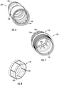
- FIG. 6 is a rear perspective view of the outer connector body of the assembly of FIG. 1 .
- FIG. 7 is a rear perspective view of the rear connector body of the assembly of FIG. 1 .
- FIG. 8 is a rear perspective view of the spring basket of the assembly of FIG. 1 .
- FIGS. 9-11 are enlarged partial side section views of the assembly of FIG. 1 being assembled.
- FIG. 12 is an enlarged partial section view of the outer conductor, rear body and spring basket of the assembly of FIG. 1 .
- FIG. 13 is a greatly enlarged partial section view of the outer connector body and rear body of the assembly of FIG. 1 .
- FIG. 14 is a greatly enlarged partial section view of the outer conductor, rear body and spring basket of the assembly of FIG. 11 .
- the assembly 100 includes a coaxial cable 110 and a connector 130 attached to one end thereof.
- the directional terms “front”, “forward” and the like refer to the direction along the longitudinal axis of the cable 110 that extends from the connector 130 toward the cable 110 .
- the directional terms “rear”, “back” and the like refer to the direction opposite the “forward” direction: i.e., along the longitudinal axis of the cable 110 that extends from the connector 130 toward the cable 110 .
- the cable 110 includes a central conductor 112 , a dielectric layer 114 that circumferentially overlies the central conductor 112 , an annularly corrugated outer conductor 116 that circumferentially overlies the dielectric layer 114 , and a polymeric cable jacket 120 that circumferentially overlies the outer conductor 116 .
- the outer conductor 116 has a flared end 117 .
- the connector 130 includes an inner contact 132 , an outer connector body 134 , a dielectric spacer 136 , an insulator 137 , a rear body 135 , and a spring basket 133 .
- the inner contact 132 has a generally cylindrical post 132 a and is mounted on and is in electrical contact with the central conductor 112 of the cable 110 via spring fingers 132 b .
- the insulator 137 surrounds the inner conductor 112 adjacent the spring fingers 132 b .
- the dielectric spacer 136 is positioned radially outwardly of the post 132 a.
- the outer conductor body 134 includes a mating ring 138 that is configured to mate with the outer conductor body of a mating jack.
- the mating ring 138 extends forwardly of a main sleeve 140 .
- a flange 142 extends radially outwardly of the main sleeve 140 and provides a bearing surface for a nut 180 .
- a shoulder 141 is located on the inner surface of the main sleeve 140 to provide a mounting location for the insulator 137 .
- the main sleeve 140 has a rim 143 .
- a series of projections 144 extend radially inward from the forward end of the rim 143 .
- a barb 145 is located forwardly of the projections 144 on the inner surface of the main sleeve 140 .
- a tapered surface 146 is located forwardly of the barb 145 .
- the spring basket 133 has an outer ring 160 that includes an angled rear surface 161 .
- Spring fingers 162 extend rearwardly from the outer ring 160 .
- the free end 163 of each of the spring fingers 162 is angled slightly radially inwardly relative to the longitudinal axis A of the spring basket 133 .
- Assembly of the cable-connector assembly 100 commences with the preparation of the cable 110 , which comprises stripping the jacket 120 to expose a portion of the outer conductor 116 . Additionally, the outer conductor 116 and dielectric layer 114 are stripped to expose the end of the inner conductor 112 . The flared end 117 of the outer conductor 116 is also prepared. The rear body 135 is then slipped over the end of the cable 110 , such that the main section 154 fits over at least a portion of the jacket 120 . In this position, the nubs 152 a of the fingers 152 b of the collet 152 are received in the endmost “root” of the corrugated outer conductor 116 .
- a subassembly comprising the inner contact 132 , the outer connector body 134 , the dielectric spacer 136 , the insulator 137 , and the spring basket 133 is slipped over the end of the cable 110 .
- This arrangement is shown in FIG. 9 .
- the projections 144 on the outer conductor body 134 contact the projections 152 d on the collet fingers 152 b , which halts the relative axial motion of the outer conductor body 134 and the rear body 133 .
- the assembly can then be rotated relative to the rear body 135 until the projections 144 align with slots between the collet fingers 152 b (see FIG. 9 ).
- the subassembly can be pushed farther rearwardly (i.e., toward the cable 110 ).
- the barb 145 on the outer conductor body 134 passes the barb 153 a on the collet fingers 152 b (see FIG. 10 ), at which time the outer connector body 134 can be released and allowed to recover forward slightly until the barbs 145 , 153 b engage ( FIG. 11 ).
- the interaction of the barbs 145 , 153 a maintains the outer connector body 134 and the rear body 135 in position.
- the fingers 132 b of the inner contact 132 receive and grip the inner conductor 112 of the cable 110 , thereby providing a sound electrical connection. Additionally, the nubs 152 a of the collet fingers 152 b force the flared end 117 of the outer conductor 116 against the angled rear surface 161 of the spring basket 133 and against the angled free ends 163 of the fingers 162 .
- This contact is enhanced by (a) engagement of the contact surface 152 c of the fingers 152 b of the collet 152 with the inner surface of the main sleeve 140 of the outer connector body 134 , which forces the nubs 152 a into the flared end 117 , and (b) resilience in the fingers 162 of the spring basket 133 , which forces the flared end 117 up into the nubs 152 a .
- This contact provides a sound electrical connection (and therefore improved PIM performance) between the outer conductor 116 and the spring basket 135 .
- the angled free ends 163 of the fingers 162 of the spring basket 133 also provide a slight rearward force on the nubs 152 a . This rearward forces drives the barb 153 a into the barb 145 , thereby providing additional mechanical stability (see FIGS. 12 and 14 ).
- Mechanical stability may also be improved due to the presence of the projections 144 between the collet fingers 152 b (and in particular between the projections 152 d ); this interaction prevents the outer connector body 134 from rotating relative to the rear body 135 once they are secured.
- the assembly 100 may take other forms.
- securing features other than the inter-engaging barbs 145 , 153 b may be employed; for example, a projection and groove arrangement may be used.
- the end of the outer conductor 116 may not be flared.
- the fingers 162 of the spring basket 133 may take a different profile.
- the spring basket 133 may be formed as two pieces (e.g., an outer ring and inner fingers) rather than as a single piece.
- Means for securing the connector 130 to a mating connector other than the coupling nut 180 may be used. Other variations may also be apparent to those of skill in this art.
Landscapes
- Coupling Device And Connection With Printed Circuit (AREA)
Abstract
Description
- (a) a coaxial cable comprising: an inner conductor; a dielectric layer circumferentially surrounding the inner conductor; an outer conductor circumferentially surrounding the dielectric layer, the outer conductor having an inner surface and an outer surface; and a jacket circumferentially surrounding the outer conductor;
- (b) a coaxial connector comprising: an inner contact electrically connected with the inner conductor; an outer connector body spaced apart from and circumferentially surrounding the inner contact, the outer connector body including a first securing feature; and a dielectric spacer interposed between the inner contact and the outer body; and
- (c) a rear body having a main section and a front collet with forwardly-extending fingers, the fingers engaging the outer surface of the outer conductor of the cable, the fingers including a second securing feature, wherein the second securing feature engages the first securing feature to maintain the outer connector body and the rear body in position on the cable.
- (a) a coaxial cable comprising: an inner conductor; a dielectric layer circumferentially surrounding the inner conductor; an outer conductor circumferentially surrounding the dielectric layer, the outer conductor having an inner surface and an outer surface; and a jacket circumferentially surrounding the outer conductor;
- (b) a coaxial connector comprising: an inner contact electrically connected with the inner conductor; an outer connector body spaced apart from and circumferentially surrounding the inner contact; and a dielectric spacer interposed between the inner contact and the outer connector body;
- (c) a rear body having a main section and a front collet with forwardly-extending fingers, the fingers engaging the outer surface of the outer conductor of the cable; and
- (d) a spring basket with rearwardly-extending fingers, the spring basket positioned radially inwardly of the outer connector body, the fingers of the spring basket engaging the inner surface of the outer conductor.
- (a) providing a coaxial cable comprising: an inner conductor; a dielectric layer circumferentially surrounding the inner conductor; an outer conductor circumferentially surrounding the dielectric layer, the outer conductor having an inner surface and an outer surface; and a jacket circumferentially surrounding the outer conductor;
- (b) providing a coaxial connector comprising: an inner contact electrically connected with the inner conductor; an outer connector body spaced apart from and circumferentially surrounding the inner contact, the outer connector body including a first securing feature on an inner surface thereof;
- (c) providing a rear body having an annular main section and a front collet with forwardly-extending fingers, the fingers including a second securing feature;
- (d) sliding the rear body onto the coaxial cable so that the front collet fingers engage the outer surface of the outer conductor of the cable; and
- (e) sliding the coaxial connector onto the rear body and the coaxial cable such that the inner contact engages the inner conductor, the outer conductor body engages the front collet fingers, and the first securing features engage the second securing features to maintain the outer connector body and the rear body in position on the cable.
Claims (18)
Priority Applications (2)
| Application Number | Priority Date | Filing Date | Title |
|---|---|---|---|
| US17/027,854 US11283201B2 (en) | 2019-10-07 | 2020-09-22 | Easily assembled coaxial cable and connector with rear body |
| US17/691,706 US11677172B2 (en) | 2019-10-07 | 2022-03-10 | Easily assembled coaxial cable and connector with rear body |
Applications Claiming Priority (2)
| Application Number | Priority Date | Filing Date | Title |
|---|---|---|---|
| US201962911480P | 2019-10-07 | 2019-10-07 | |
| US17/027,854 US11283201B2 (en) | 2019-10-07 | 2020-09-22 | Easily assembled coaxial cable and connector with rear body |
Related Child Applications (1)
| Application Number | Title | Priority Date | Filing Date |
|---|---|---|---|
| US17/691,706 Continuation US11677172B2 (en) | 2019-10-07 | 2022-03-10 | Easily assembled coaxial cable and connector with rear body |
Publications (2)
| Publication Number | Publication Date |
|---|---|
| US20210104827A1 US20210104827A1 (en) | 2021-04-08 |
| US11283201B2 true US11283201B2 (en) | 2022-03-22 |
Family
ID=75274397
Family Applications (2)
| Application Number | Title | Priority Date | Filing Date |
|---|---|---|---|
| US17/027,854 Active US11283201B2 (en) | 2019-10-07 | 2020-09-22 | Easily assembled coaxial cable and connector with rear body |
| US17/691,706 Active US11677172B2 (en) | 2019-10-07 | 2022-03-10 | Easily assembled coaxial cable and connector with rear body |
Family Applications After (1)
| Application Number | Title | Priority Date | Filing Date |
|---|---|---|---|
| US17/691,706 Active US11677172B2 (en) | 2019-10-07 | 2022-03-10 | Easily assembled coaxial cable and connector with rear body |
Country Status (4)
| Country | Link |
|---|---|
| US (2) | US11283201B2 (en) |
| EP (1) | EP4042518A1 (en) |
| CN (1) | CN114503375A (en) |
| WO (1) | WO2021071656A1 (en) |
Families Citing this family (3)
| Publication number | Priority date | Publication date | Assignee | Title |
|---|---|---|---|---|
| US20230010610A1 (en) * | 2021-07-09 | 2023-01-12 | Commscope Technologies Llc | Coaxial cable and connector assemblies and methods of assembling same |
| CN114221159B (en) * | 2021-12-23 | 2023-08-29 | 杭州摩光通讯器材有限公司 | Connector for hollow cable |
| CN119726027A (en) * | 2024-12-31 | 2025-03-28 | 京信射频技术(广州)有限公司 | RF connectors, cavity devices and RF devices |
Citations (8)
| Publication number | Priority date | Publication date | Assignee | Title |
|---|---|---|---|---|
| US4046451A (en) * | 1976-07-08 | 1977-09-06 | Andrew Corporation | Connector for coaxial cable with annularly corrugated outer conductor |
| EP0495467A2 (en) | 1991-01-15 | 1992-07-22 | Andrew A.G. | Self-flaring connector for coaxial cable having a helically corrugated outer conductor |
| US5595502A (en) | 1995-08-04 | 1997-01-21 | Andrew Corporation | Connector for coaxial cable having hollow inner conductor and method of attachment |
| US5993254A (en) | 1997-07-11 | 1999-11-30 | Spinner Gmbh Elektrotechnische Fabrik | Connector for coaxial cables with improved contact-making between connector head and outer cable connector |
| EP1206011A1 (en) | 2000-11-14 | 2002-05-15 | Radio Frequency Systems Inc. | One step connector |
| US7637774B1 (en) * | 2008-08-29 | 2009-12-29 | Commscope, Inc. Of North Carolina | Method for making coaxial cable connector components for multiple configurations and related devices |
| US20100190377A1 (en) * | 2009-01-28 | 2010-07-29 | Andrew Llc, State/Country Of Incorporation: Delaware | Connector including flexible fingers and associated methods |
| CN108028476A (en) | 2015-11-05 | 2018-05-11 | 康普技术有限责任公司 | Easy-to-assemble coaxial cable, connector, and rear body |
Family Cites Families (1)
| Publication number | Priority date | Publication date | Assignee | Title |
|---|---|---|---|---|
| CN108628476A (en) | 2018-04-28 | 2018-10-09 | 北京奇禄管理咨询有限公司 | A kind of writing device |
-
2020
- 2020-09-21 CN CN202080069564.4A patent/CN114503375A/en active Pending
- 2020-09-21 WO PCT/US2020/051758 patent/WO2021071656A1/en not_active Ceased
- 2020-09-21 EP EP20875586.8A patent/EP4042518A1/en not_active Withdrawn
- 2020-09-22 US US17/027,854 patent/US11283201B2/en active Active
-
2022
- 2022-03-10 US US17/691,706 patent/US11677172B2/en active Active
Patent Citations (8)
| Publication number | Priority date | Publication date | Assignee | Title |
|---|---|---|---|---|
| US4046451A (en) * | 1976-07-08 | 1977-09-06 | Andrew Corporation | Connector for coaxial cable with annularly corrugated outer conductor |
| EP0495467A2 (en) | 1991-01-15 | 1992-07-22 | Andrew A.G. | Self-flaring connector for coaxial cable having a helically corrugated outer conductor |
| US5595502A (en) | 1995-08-04 | 1997-01-21 | Andrew Corporation | Connector for coaxial cable having hollow inner conductor and method of attachment |
| US5993254A (en) | 1997-07-11 | 1999-11-30 | Spinner Gmbh Elektrotechnische Fabrik | Connector for coaxial cables with improved contact-making between connector head and outer cable connector |
| EP1206011A1 (en) | 2000-11-14 | 2002-05-15 | Radio Frequency Systems Inc. | One step connector |
| US7637774B1 (en) * | 2008-08-29 | 2009-12-29 | Commscope, Inc. Of North Carolina | Method for making coaxial cable connector components for multiple configurations and related devices |
| US20100190377A1 (en) * | 2009-01-28 | 2010-07-29 | Andrew Llc, State/Country Of Incorporation: Delaware | Connector including flexible fingers and associated methods |
| CN108028476A (en) | 2015-11-05 | 2018-05-11 | 康普技术有限责任公司 | Easy-to-assemble coaxial cable, connector, and rear body |
Non-Patent Citations (1)
| Title |
|---|
| "International Search Report and Written Opinion corresponding to International Application No. PCI/US2020/051758 dated Jan. 25, 2021". |
Also Published As
| Publication number | Publication date |
|---|---|
| EP4042518A1 (en) | 2022-08-17 |
| US20210104827A1 (en) | 2021-04-08 |
| CN114503375A (en) | 2022-05-13 |
| US20220200172A1 (en) | 2022-06-23 |
| WO2021071656A1 (en) | 2021-04-15 |
| US11677172B2 (en) | 2023-06-13 |
Similar Documents
| Publication | Publication Date | Title |
|---|---|---|
| US10833432B2 (en) | Easily assembled coaxial cable and connector with rear body | |
| US11677172B2 (en) | Easily assembled coaxial cable and connector with rear body | |
| CN109256645B (en) | Quick-locking coaxial connector | |
| US11545796B2 (en) | Coaxial cable connectors having port grounding | |
| US10651574B2 (en) | Coaxial cable connectors having port grounding | |
| US11125810B2 (en) | Blind-mate PIM testing adapter connector and fixture | |
| US20160226202A1 (en) | Right angle coaxial cable and connector assembly | |
| US20240079817A1 (en) | Coupler seal for coaxial cable system components | |
| US10374335B2 (en) | Coaxial cable and connector assembly | |
| US10637172B2 (en) | Coaxial male connector, coaxial female connector and assembly thereof | |
| CN112868138A (en) | Coaxial cable connector | |
| EP3257114A1 (en) | Dielectric spacer for coaxial cable and connector | |
| EP3105822B1 (en) | Coaxial cable and connector with dielectric spacer that inhibits unwanted solder flow | |
| US9647384B2 (en) | Back body for coaxial connector | |
| US20220385009A1 (en) | Coaxial cable and connector with adapter to facilitate assembly | |
| US20050202706A1 (en) | Snap ring connector system |
Legal Events
| Date | Code | Title | Description |
|---|---|---|---|
| FEPP | Fee payment procedure |
Free format text: ENTITY STATUS SET TO UNDISCOUNTED (ORIGINAL EVENT CODE: BIG.); ENTITY STATUS OF PATENT OWNER: LARGE ENTITY |
|
| AS | Assignment |
Owner name: COMMSCOPE TECHNOLOGIES LLC, NORTH CAROLINA Free format text: ASSIGNMENT OF ASSIGNORS INTEREST;ASSIGNOR:PAYNTER, JEFFREY D.;REEL/FRAME:054965/0964 Effective date: 20210119 |
|
| STPP | Information on status: patent application and granting procedure in general |
Free format text: DOCKETED NEW CASE - READY FOR EXAMINATION |
|
| STPP | Information on status: patent application and granting procedure in general |
Free format text: NON FINAL ACTION MAILED |
|
| STPP | Information on status: patent application and granting procedure in general |
Free format text: RESPONSE TO NON-FINAL OFFICE ACTION ENTERED AND FORWARDED TO EXAMINER |
|
| AS | Assignment |
Owner name: JPMORGAN CHASE BANK, N.A., NEW YORK Free format text: ABL SECURITY AGREEMENT;ASSIGNORS:ARRIS ENTERPRISES LLC;COMMSCOPE TECHNOLOGIES LLC;COMMSCOPE, INC. OF NORTH CAROLINA;REEL/FRAME:058843/0712 Effective date: 20211112 Owner name: JPMORGAN CHASE BANK, N.A., NEW YORK Free format text: TERM LOAN SECURITY AGREEMENT;ASSIGNORS:ARRIS ENTERPRISES LLC;COMMSCOPE TECHNOLOGIES LLC;COMMSCOPE, INC. OF NORTH CAROLINA;REEL/FRAME:058875/0449 Effective date: 20211112 |
|
| AS | Assignment |
Owner name: WILMINGTON TRUST, DELAWARE Free format text: SECURITY INTEREST;ASSIGNORS:ARRIS SOLUTIONS, INC.;ARRIS ENTERPRISES LLC;COMMSCOPE TECHNOLOGIES LLC;AND OTHERS;REEL/FRAME:060752/0001 Effective date: 20211115 |
|
| STPP | Information on status: patent application and granting procedure in general |
Free format text: NOTICE OF ALLOWANCE MAILED -- APPLICATION RECEIVED IN OFFICE OF PUBLICATIONS |
|
| STCF | Information on status: patent grant |
Free format text: PATENTED CASE |
|
| CC | Certificate of correction | ||
| AS | Assignment |
Owner name: OUTDOOR WIRELESS NETWORKS LLC, NORTH CAROLINA Free format text: ASSIGNMENT OF ASSIGNORS INTEREST;ASSIGNOR:COMMSCOPE TECHNOLOGIES LLC;REEL/FRAME:068492/0826 Effective date: 20240715 |
|
| AS | Assignment |
Owner name: JPMORGAN CHASE BANK, N.A., AS COLLATERAL AGENT, NEW YORK Free format text: PATENT SECURITY AGREEMENT (TERM);ASSIGNOR:OUTDOOR WIRELESS NETWORKS LLC;REEL/FRAME:068770/0632 Effective date: 20240813 Owner name: JPMORGAN CHASE BANK, N.A., AS COLLATERAL AGENT, NEW YORK Free format text: PATENT SECURITY AGREEMENT (ABL);ASSIGNOR:OUTDOOR WIRELESS NETWORKS LLC;REEL/FRAME:068770/0460 Effective date: 20240813 |
|
| AS | Assignment |
Owner name: APOLLO ADMINISTRATIVE AGENCY LLC, NEW YORK Free format text: SECURITY INTEREST;ASSIGNORS:ARRIS ENTERPRISES LLC;COMMSCOPE TECHNOLOGIES LLC;COMMSCOPE INC., OF NORTH CAROLINA;AND OTHERS;REEL/FRAME:069889/0114 Effective date: 20241217 |
|
| AS | Assignment |
Owner name: OUTDOOR WIRELESS NETWORKS LLC, NORTH CAROLINA Free format text: RELEASE OF SECURITY INTEREST AT REEL/FRAME 068770/0632;ASSIGNOR:JPMORGAN CHASE BANK, N.A., AS COLLATERAL AGENT;REEL/FRAME:069743/0264 Effective date: 20241217 Owner name: COMMSCOPE TECHNOLOGIES LLC, NORTH CAROLINA Free format text: RELEASE OF SECURITY INTEREST AT REEL/FRAME 058875/0449;ASSIGNOR:JPMORGAN CHASE BANK, N.A., AS COLLATERAL AGENT;REEL/FRAME:069743/0057 Effective date: 20241217 Owner name: COMMSCOPE, INC. OF NORTH CAROLINA, NORTH CAROLINA Free format text: RELEASE OF SECURITY INTEREST AT REEL/FRAME 058875/0449;ASSIGNOR:JPMORGAN CHASE BANK, N.A., AS COLLATERAL AGENT;REEL/FRAME:069743/0057 Effective date: 20241217 Owner name: ARRIS ENTERPRISES LLC (F/K/A ARRIS ENTERPRISES, INC.), NORTH CAROLINA Free format text: RELEASE OF SECURITY INTEREST AT REEL/FRAME 058875/0449;ASSIGNOR:JPMORGAN CHASE BANK, N.A., AS COLLATERAL AGENT;REEL/FRAME:069743/0057 Effective date: 20241217 |
|
| AS | Assignment |
Owner name: OUTDOOR WIRELESS NETWORKS LLC, NORTH CAROLINA Free format text: PARTIAL TERMINATION AND RELEASE OF SECURITY INTEREST IN PATENTS RECORDED AT REEL 069889/FRAME 0114;ASSIGNOR:APOLLO ADMINISTRATIVE AGENCY LLC;REEL/FRAME:070154/0341 Effective date: 20250131 Owner name: OUTDOOR WIRELESS NETWORKS LLC, NORTH CAROLINA Free format text: PARTIAL TERMINATION AND RELEASE OF SECURITY INTEREST IN PATENTS;ASSIGNOR:U.S. BANK TRUST COMPANY, NATIONAL ASSOCIATION;REEL/FRAME:070154/0183 Effective date: 20250131 Owner name: OUTDOOR WIRELESS NETWORKS LLC, NORTH CAROLINA Free format text: RELEASE (REEL 068770 / FRAME 0460);ASSIGNOR:JPMORGAN CHASE BANK, N.A.;REEL/FRAME:070149/0432 Effective date: 20250131 |
|
| FEPP | Fee payment procedure |
Free format text: MAINTENANCE FEE REMINDER MAILED (ORIGINAL EVENT CODE: REM.); ENTITY STATUS OF PATENT OWNER: LARGE ENTITY |